Article

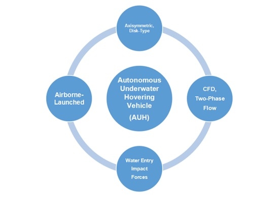
Computational Fluid Dynamics Study of Water Entry Impact Forces of an Airborne-Launched, Axisymmetric, Disk-Type Autonomous Underwater Hovering Vehicle

Institute of Marine Structures and Naval Architecture, Ocean College, Zhejiang University, Zhoushan 316000, China
*
Author to whom correspondence should be addressed.
Symmetry 2019, 11(9), 1100; https://doi.org/10.3390/sym11091100
Submission received: 2 August 2019 / Revised: 17 August 2019 / Accepted: 20 August 2019 / Published: 2 September 2019
(This article belongs to the Special Issue Aero/Hydrodynamics and Symmetry)

Abstract

:
An autonomous underwater hovering vehicle (AUH) is a novel, dish-shaped, axisymmetric, multi-functional, ultra-mobile submersible in the autonomous underwater vehicle (AUV) family. Numerical studies of nonlinear, asymmetric water entry impact forces on symmetrical, airborne-launched AUVs from conventional single-arm cranes on a research vessel, or helicopters or planes, is significant for the fast and safe launching of low-speed AUVs into the target sea area in the overall design. Moreover, a single-arm crane is one of the important ways to launch AUVs with high expertise and security. However, AUVs are still subject to a huge load upon impact during water entry, causing damage to the body, malfunction of electronic components, and other serious accidents. This paper analyses the water entry impact forces of an airborne-launched AUH as a feasibility study for flight- or helicopter-launched AUHs in the future. The computational fluid dynamics (CFD) analysis software STAR-CCM+ solver was adopted to simulate AUH motions with different water entry speeds and immersion angles using overlapping grid technology and user-defined functions (UDFs). In the computational domain for a steady, incompressible, two-dimensional flow of water with identified boundary conditions, two components (two-phase flow) were modeled in the flow field: Liquid water and free surface air. The variations of stress and velocity versus time of the AUH and fluid structure deformation in the whole water entry process were obtained, which provides a reference for future structural designs of an AUH and appropriate working conditions for an airborne-launched AUH. This research will be conducive to smoothly carrying out the complex tasks of AUHs on the seabed.

Graphical Abstract

1. Introduction

Abundant mineral resources, power sources, and biological resources are conserved in the ocean, which is meaningful for economic development [1]. Because of the dark and hypoxic environment underwater, the need for an unmanned machine to replace people to complete underwater inventions is imperative. Autonomous underwater vehicles (AUVs) have a wide range of applications in oceanic geoscience, and they were created to accomplish resource exploration tasks on the seabed, including energy exchange, pipeline inspection, and roaming the deep-sea seabed [2]. AUVs have revolutionized our ability to detect and image the seabed with the real-time ability to exchange high-resolution, oceanographic, photomosaic information at abyssal depths [3,4,5]. However, conventional axisymmetric, torpedo-shaped AUVs have poor maneuverability when swaying and yawing because the added mass and added moment of inertia of the slender body dominates, which causes unstable AUV motions due to the occurrence of the Munk effect. In addition, motion instability in heave situations results from inefficient surface control in low-velocity conditions. Thus, the conventional horizontal, axisymmetric AUVs cannot effectively and efficiently accomplish unplanned super-mobile hovering tasks, for example, random landing and launching on the seabed, random hovering at some specified oceanic depth, providing services for a submarine mobile observation network, exploring submarine resources, connecting submarine operating point data in a specified smaller seabed area, and so on.
An autonomous underwater hovering vehicle (AUH), with a vertical, symmetric structural design, is a novel, dish-shaped, multi-functional, ultra-mobile submersible in the AUV family. AUHs are subject to high demands, for example, high-level and autonomous functionality, enhanced maneuverability in horizontal and vertical planes, adaptive landing and launching on the seabed, and the need to easily hover in the deep sea. The disk-shaped AUH was proposed at the Ocean College of Zhejiang University in 2016 to greatly enhance the motion stability during heaving, enable the AUH to hover in the deep sea, and improve the maneuverability of conventional, slender AUVs in yawing and swaying, including an enhanced anti-flow ability in the deep sea [6,7].
The structural design of the AUH is shown in Figure 1. This AUH could transmit data between base stations on the deep-sea bottom to communicate with scientific research ships near the free surface. The conceptual design of the AUH includes a symmetric, disk-shaped hull form, a pressure hull of 15 MPa, an energy power system, a control system, a navigation system, a communication system, and mission payload technology, e.g., recovering, landing, and launching models. The mission payload technology design in this study, i.e., airborne-launched technology, can enhance the effectiveness and efficiency of AUH missions. Thus, the study of the water entry impact forces on the disk-type AUH hull, with different water entry velocities and attitudes from a certain height, shall be carried out in this paper.
Research on launch and recovery systems for AUVs is significant to aid in the overall design process and guarantees successful, smooth deployment and operation of the AUH from the free surface to the deep sea [8]. The AUH hull was mounted with precise sensors, which were often damaged and lost from excessive water impact forces when the AUH was deployed and launched.
Traditionally, two main methods of AUV deployment are often adopted, i.e., a shore-based deployment or deployment by a scientific research ship [9]. Shore-based deployment technology is relatively mature; however, this needs excellent hardware support and good sea weather. Deployment by a scientific research ship is more difficult and brings about great uncertainty under atrocious sea conditions and other restrictions. Deployments by a scientific research ship include several forms: Deployment of a scientific research ship, an underwater vehicle (UV), and/or an unmanned surface vehicle (USV). An automated launch and recovery system for AUVs from an unmanned surface vehicle was proposed by Edoardo and Manhar [10].
Scientific research ships can be mounted with several launch and recovery devices, including conventional crane forms, A-shaped cranes, dedicated single-arm cranes, sliding cranes, and integrated cranes. Conventional forms are advantageous because of their simple structures and low costs; however, the operation is complex, and they are not as safe. A-shaped cranes have been widely adopted because of their simple operation. Dedicated single-arm crane systems are very safe, as shown in Figure 2. They greatly simplify operation processes and save costs [11]; however, time-consuming deployment and its inefficiency to quickly launch multiple AUVs to target sea areas are its weaknesses. Sliding-type crane systems are mainly used to continuously lay equipment or different types of remotely operated vehicle (ROV) cables. An integrated layout and recovery system operates, more or less, independently from the scientific research ship and has a high safety factor. Deployment of AUVs is better from a submarine than from a scientific research ship; however, recovering the AUVs is difficult. USV- and UV-based deployments need further improvement in order to be practical and reliable [10].
In particular, airborne launch methods that use planes or helicopters to quickly launch AUVs into target sea areas have received more attention by scientists and strategists recently [11,12,13,14,15,16,17,18,19,20,21]. Scholars have conducted a lot of research to investigate water entry impact forces, trajectory deflection, and damage to an airborne-launched AUV, especially when the maximum impact loads occur in the initial entry stages [11].
Xia et al. [15] studied the water entry impact forces of an inclined, axisymmetric, slender body with a horizontal velocity and multiple degrees of motion freedom on the free surface. The effects of horizontal velocity, angle of attack, and inclined angle on the motion characteristics of the axisymmetric slender body were studied. A circuitous phenomenon was found when the angle of attack was greater than 22 .
Wang et al. [17] established an oblique water entry impact model, coupled with dynamic ballistic models, which was based on the theory of potential flow and the precise shape of the coupling surface between the fluid and the solid.
Qiu et al. [18] carried out simulations of the water entry impact forces on axisymmetric bodies, which was based on water entry dynamics and ballistic theories, to obtain the maximum impact load. The initial water entry conditions and the relationship between water entry impact loads were simulated. The simulation tests implemented relevant water entry processes for the revolution bodies (e.g., flat head, cone head, and round head), using commercial computational fluid dynamics (CFD) software FLUENT technologies, including dynamic mesh, user-defined functions (UDFs), and a mixture (MIXTURE) process model. The effects of velocity and head shape on the impact load and shape of cavitation were studied.
Qi et al. [19] presented the impact load of an AUV model under various water entry conditions as well as the varied rules of axial and radial forces during water infiltration through experiments and viscous CFD simulation methods. Reference data on the structural design and projection conditions of the AUV were provided.
Shi et al. [20] designed an inlet cap for an AUV and analyzed the influence of the buffer cap’s structural design, material density, buffer distance, water flow velocity, and buffer effect of initial buffer on the water entry angles.
Ma et al. [21] implemented experimental investigations and analyzed the vertical water entry of a sphere. During water entry, the velocities, accelerations, and drag coefficients of the spheres were studied. The investigated results showed that the motion trajectory of the spheres presented highly nonlinear characteristics and notable fluctuations of the motion parameters, which were proportional to the entry speed.
In this paper, research on simulated water entry impact forces of an airborne-launched disk-type AUH based on the CFD method was implemented. The creative AUH hull form was different from the above water entry geometric shapes in literature. The STAR-CCM+ CFD Reynolds-averaged Navier–Stokes (RANS) solver was adopted to simulate air-launched AUH dynamic motions with different water entry speeds and immersion angles using the STAR-CCM+ volume of fluid (VOF) method, overlapping grid technology, and user-defined functions (UDFs). The simulation analysis was carried out under different water entry speeds and angles of the launched AUH in calm sea conditions. The variations of load and velocity of the disk-type AUH versus different states were obtained, i.e., in different initial free-fall velocities and water entry immersion angles. This study can provide an important reference for the disk-type, vertical, axisymmetric body of the AUHs to improve the structural design and adapt to the launching conditions, and it can enhance the effectiveness and efficiency of AUV deployments in order to smoothly carry out more complex tasks on the seabed.

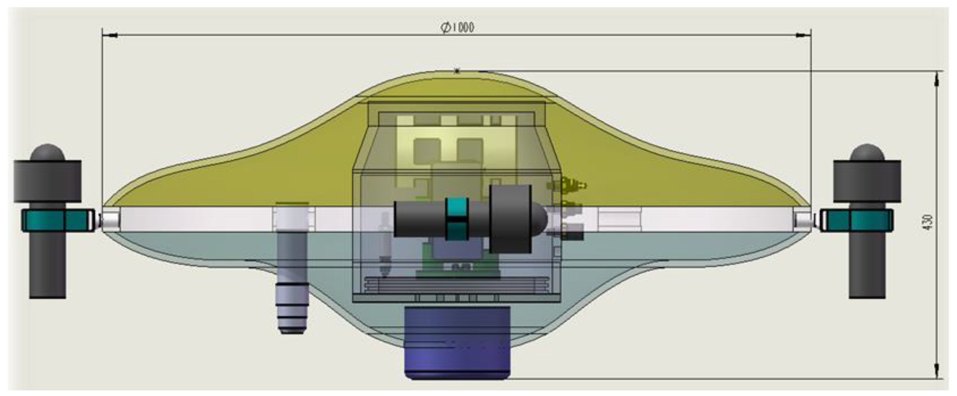
2. Configuration of the AUH

In this paper, research on simulated water entry impact forces of the hung, air-launched AUH was carried out. The main parameters of the AUH are shown in Table 1, and the disk-shaped AUH prototype in the test pool is shown in Figure 3. Both Earth-fixed and body-fixed coordinates were established to describe the water impact loads and motion of the AUH, as shown in Figure 4. In the body-fixed coordinates, the hydrodynamic forces (surge, sway, and heave) and moments (roll, pitch, and yaw) exerted on the AUH in six-degrees of freedom can be designated as X, Y, Z, K, M, and N, respectively. The impact forces on the AUH were estimated in the body-fixed coordinate in this study, including the surge force (expressed in terms of X-force) and heave force (expressed as Z-force).

3. Numerical Simulation of the Impact on Water Entry

This section describes the basic principles of solving the Navier–Stokes (N-S) equation by using the k ε model. It also introduces the setting to calculate the AUH water domain and boundary conditions (BC).

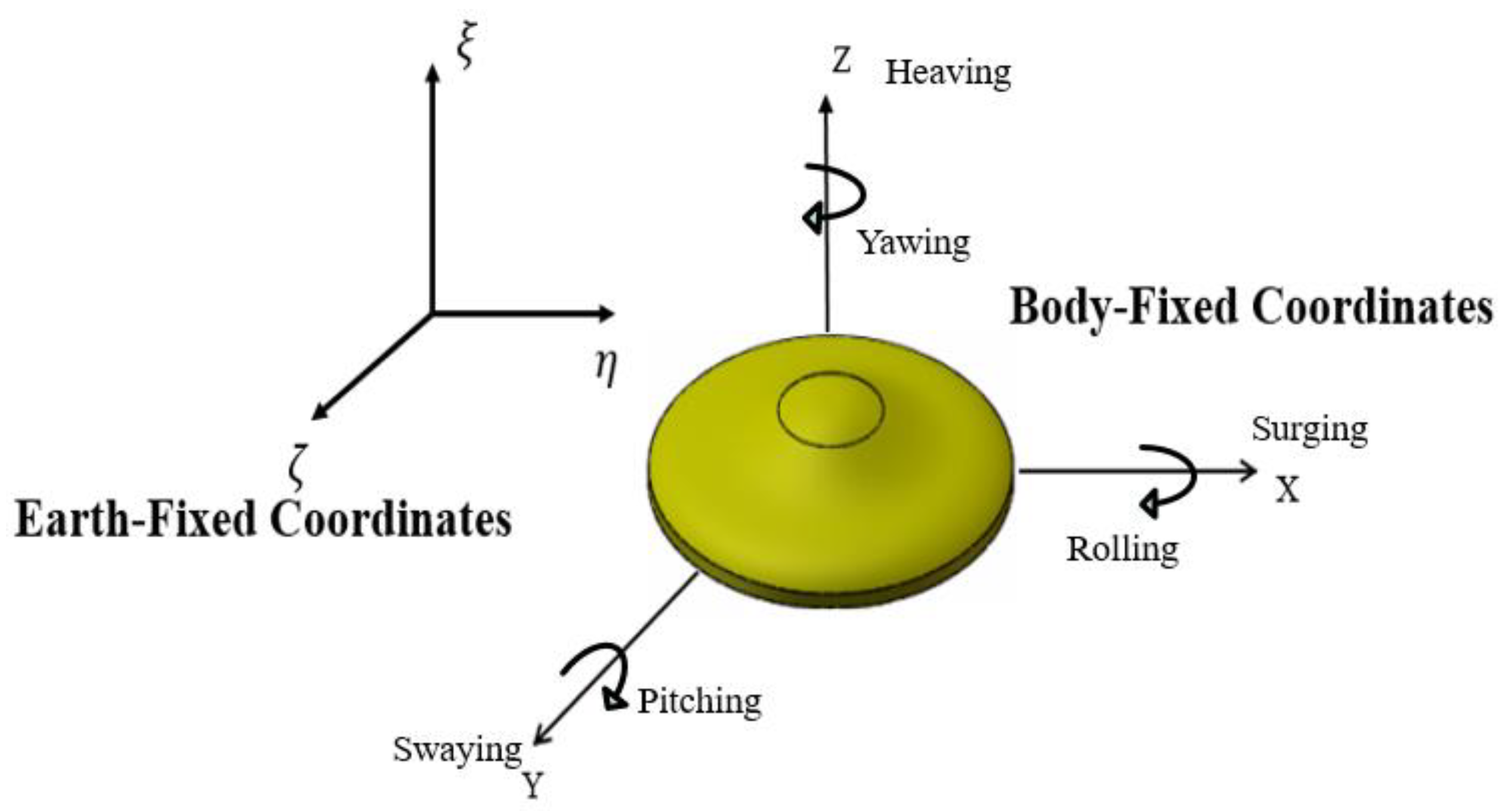
3.1. N-S Governing Equations and Turbulence Models

Reynolds-averaged Navier–Stokes (RANS) equations were solved by a numerical method using the software STAR-CCM+ as follows [22]:
( u i ¯ ) x i = 0 ,
( ρ u i ¯ ) t + ρ u j ¯ u i ¯ x j = ρ F i ¯ P ¯ x i + x j ( μ u i ¯ x j ρ u i u j ¯ ) ,
where ui denotes the component of the average speed, u i denotes the turbulent fluctuation velocity component relative to the hourly average flow velocity, F ¯ i denotes the component of the mass force, P ¯ denotes the pressure, μ is the fluid dynamic viscosity coefficient, and ρ u i u j ¯ denotes the Reynolds average stress.
The RANS equations are the current focus of computational fluid dynamics research. This method introduces fewer assumptions and is a method to calculate the viscous flow field with higher accuracy. Since RANS equations are not closed by themselves, a supplementary equation needs to be introduced to close it. Three of the most popular two-equation turbulence models, i.e., k ε model, k ω model, and k τ model, have been introduced in the literature [23]. In this paper, the k ε turbulence model and the STAR-CCM+ CFD solver were integrated with the volume of fluid (VOF) method, overlapping grid technology, and user-defined functions (UDFs) to simulate different situations of the disk-type AUH immersing into water, including varying the water entry velocities and angles of the AUH.
The two-equation turbulence model k ε , i.e., turbulent kinetic energy k and turbulent dissipation rate ε , is expressed as follows [24]:
k = u i u j ¯ 2 = 1 2 ( u 2 ¯ + v 2 ¯ + w 2 ¯ )
ε = u ρ ( u j x k ) ( u i x k ) ¯ .
In the two-equation turbulence model k ε , the corresponding transport equation can be expressed as follows:
{ ( ρ k ) t + ( ρ k u i ) x i = x j [ ( μ + μ i σ k ) k x j ] + G k + G b ρ ε Y M + S k ( ρ ε ) t + ( ρ ε u i ) x i = x j [ ( μ + μ i σ ε ) ε x j ] + G 1 ε ε k ( G k + G 3 ε G b ) G 2 ε ρ ε 2 k + S ε
where G k denotes generation of turbulent kinetic energy; k is caused by the average speed gradient; G b denotes generation of turbulent kinetic energy caused by buoyancy; Y M is the contribution of pulsatile expansion in compressible turbulence; G 1 ε , G 2 ε , and G 3 ε denote the empirical constants; σ k and σ ε denote the Prandtl numbers corresponding to the turbulent kinetic energy k and dissipation rate ε, respectively; and S k and S ε denote the user-defined source items.
The VOF method was adopted to tackle the problem of free surfaces. Both the liquid phase (water) and the gas phase (air) above the free surfaces are treated clearly by putting forward a (liquid) volume fraction α1 and gas volume fraction α2. The combined volume fraction of both phases should satisfy the conservation property. A conservation equation was solved to transport the volume fraction of one of the phases in this study. The density, ρ, and viscosity, μ, at any point are acquired by averaging volume phases as follows [25]:
{ ρ = α ρ w a t e r + ( 1 α ) ρ a i r μ = α μ w a t e r + ( 1 α ) μ a i r .
A single momentum equation was solved for the whole domain, resulting in a shared velocity field for both phases. The VOF defines a step function, α, equal to unity at any point occupied by water, and zero elsewhere, such that for volume fraction α, three conditions are considered as follows:
α = { 1 0 0 < α < 1 if if if cell cell cell is is contains full full both of of water water air and air .
The VOF method adopted to treat two-phase flows has been given in detail in Hirt and Nichols (1981) [26]. Tracking the interface between air and water is completed by solving a volume fraction continuity equation as follows:
α t + U j α x j = 0 .

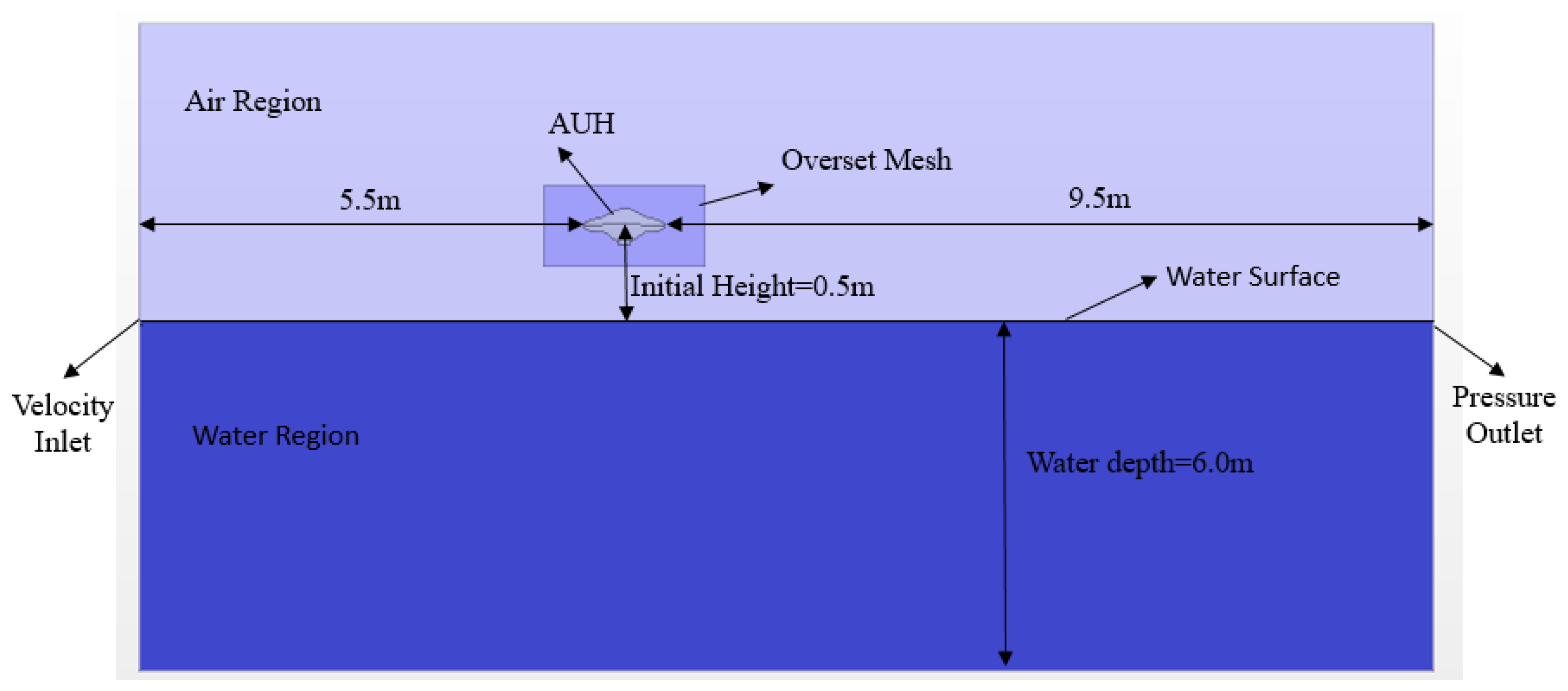
3.2. Boundary Conditions

As shown in Figure 5, the computational domain for a steady, incompressible, two-dimensional flow of water with physically specified boundary conditions (BC) was identified. Two compounds were modeled in the flow field: Liquid water and air above the free surface of the calm sea. The AUH model was 1.0 m in diameter and 0.45 m in height. The coordinate origin was arranged at the center of gravity (CG) of the model. The computational domain was rectangular with the dimensions of 25.0   m × 3 . 0   m × 10 . 0   m , and the overset area near the AUH, where STAR-CCM+ overlapping grid technology was implemented, had the dimensions of 2.0   m × 1 . 0   m × 1 . 0   m . The velocity inlet was specified at 5.5 m upstream of the AUH bow. The pressure outlet was specified at 9.5 m downstream of the AUH. The initial height of the AUH model was specified as 0.5 m above the free surface, and the water depth was set as 6.0 m.

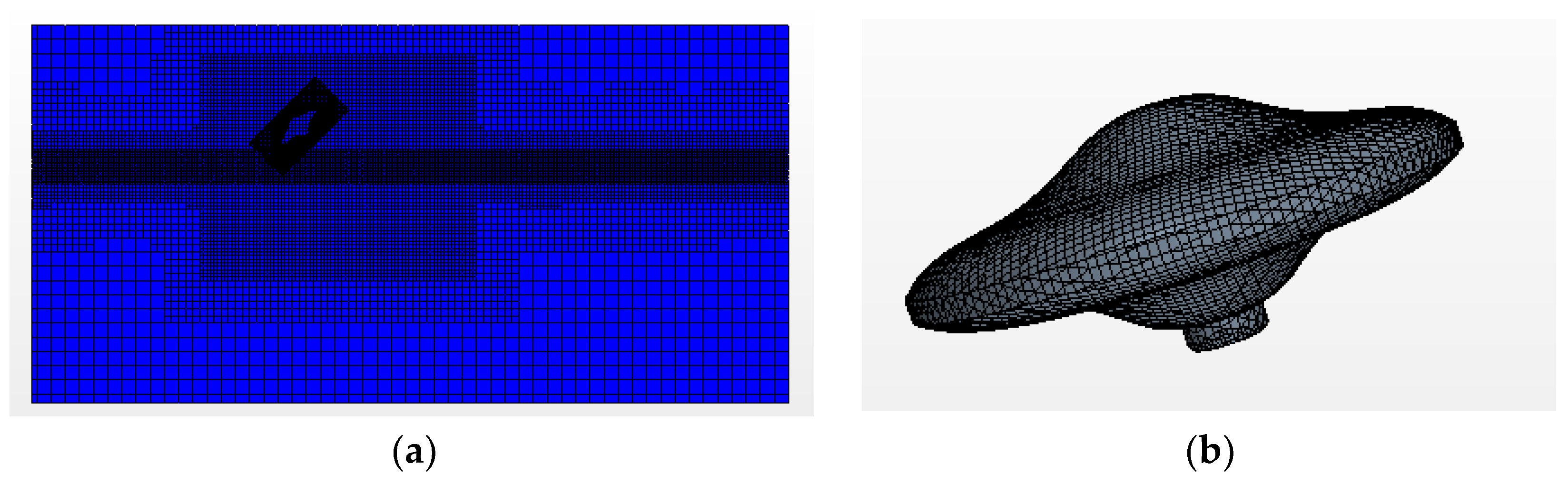
3.3. Meshing the Computational Domain

The CFD meshes could be divided into two categories: Structured meshes and unstructured meshes [27]. A hybrid mesh integrates structured and unstructured meshes to increase the mesh density near walls. In this paper, six hexahedron meshes were adopted by using a cutting mesh generator, and the total number of cells was 1.0 × 10 6 . The encryption process of meshing the AUH required a minimum mesh size of 7.5 × 10 3 m to ensure an accurate solution for the turbulence model that could meet y+ values greater than 30 [28]. It is worth mentioning that, to clearly simulate the variable process of AUH immersing into the water, meshing encryption at the air–water interface needs to be arranged, and connatural and miscellaneous dimensions need to be activated in the cutting mesh generator. The generated meshes of the two-phase flow and AUH are shown in Figure 6.

4. Simulation Results

This chapter introduces the water inflow process of AUH. It analyzes the changes to load and velocity in all directions during the AUH water inflow, and it analyzes the maximum load of the AUH at different velocities and at different water inlet angles.

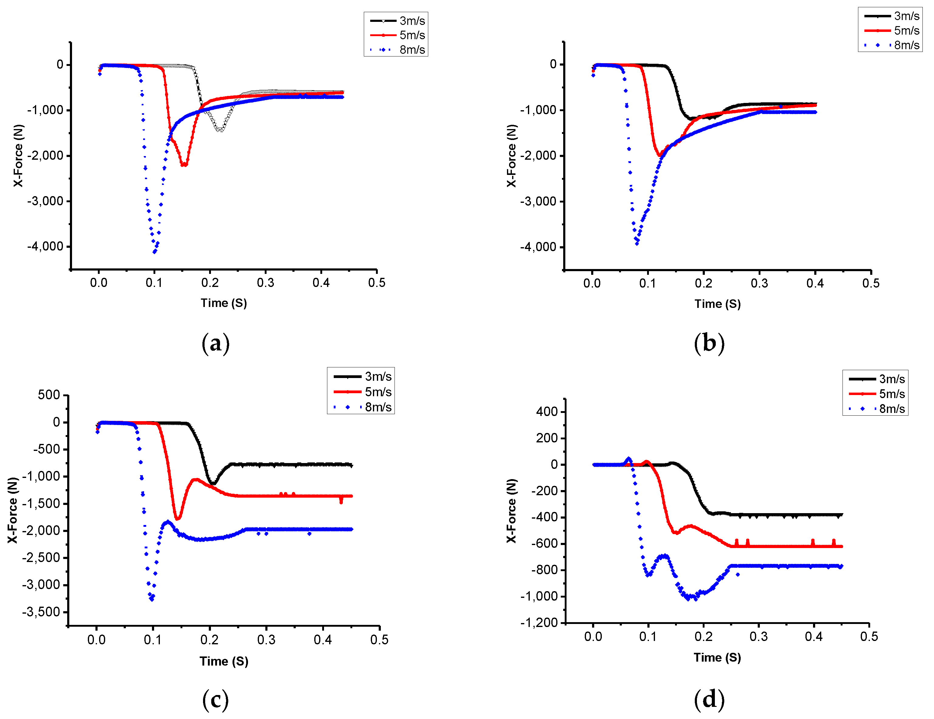
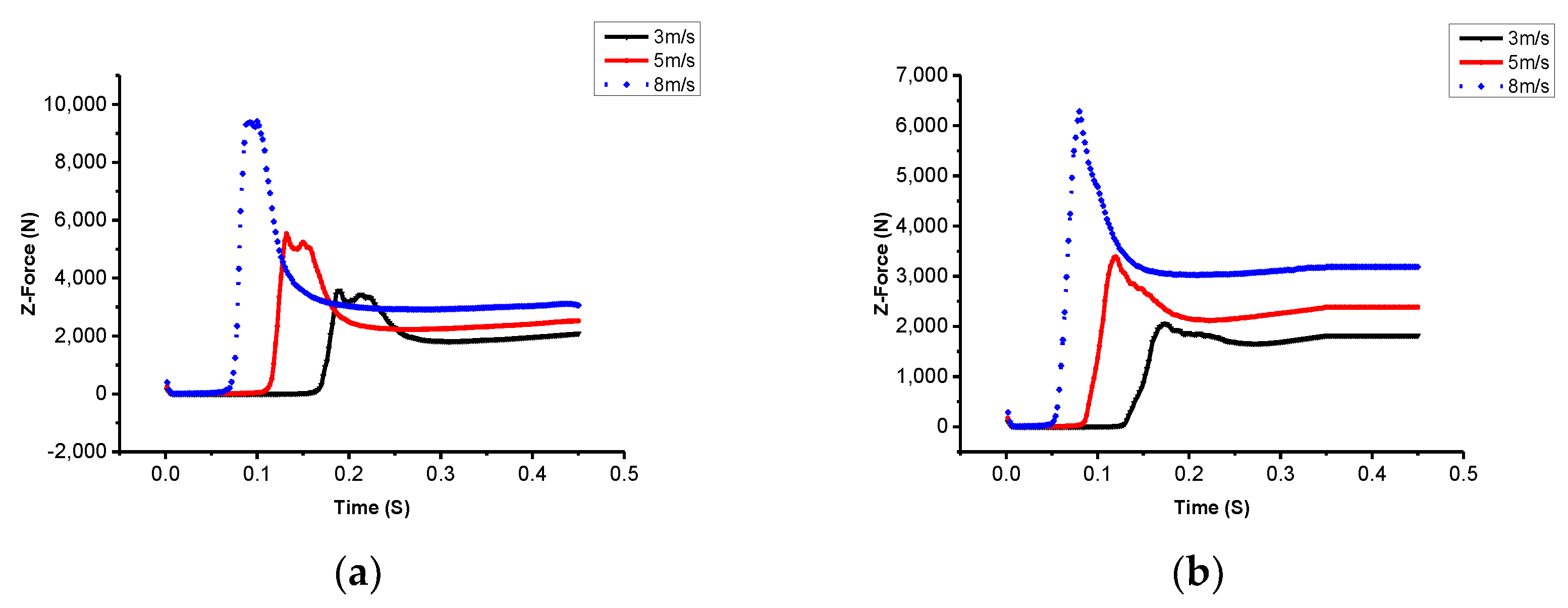
4.1. Impact Force Load of the Water Entry Process

In this paper, the k ε turbulence model and the VOF method simulation technique in STAR-CCM+ software were adopted to simulate different situations of the AUH immersing into water from 0.5 m above the surface at different initial velocities. Figure 7a,b shows the two-phase flow simulation of the AUH water entry at an initial velocity of 3 m/s with different immersion angles: 30° and 60°, respectively. Distribution of the volume fraction of water to air is shown in the CFD simulation results (Figure 7). A time-varying, deformable cavity formed, and free surfaces were captured while the AUH was immersed into the water with immersion angles of 30°, 45°, 60°, and 90°. The initial velocities of the AUH were set to 3–8 m/s. In summary, since the forces acting on the symmetric, disk-type, non-spinning, inclined AUH after the impact are dictated by the cavity’s dynamics, they are also affected by free surface conditions in cases where the cavity forms asymmetrically. The asymmetric degree of the formed cavity is highly correlated with the water entry velocity and immersion angle of the AUH.
Figure 8a–d shows that the surge force (X-force) changes under different immersion conditions during the initial AUH free fall, where the surge impact force on the AUH was measured with the body-fixed coordinates. When the AUH immersed into the water, the surge force reached the maximum value and then slowly decreased to a stable value. At the same immersion angle, the greater the initial velocity was, the greater the impact on the AUH. At the same initial speed, with an increase in the immersion angle of the AUH, the impact force on the AUH decreased. Notably, at the highest initial velocity of 8 m/s, the impact momentum of the surge on the AUH was smaller when the immersion angle was 90°, whereas a lower immersion angle of 30° caused a prominent impulsive force on the disk-type AUH.
Figure 9a–d shows the variations of the heave force (Z-force) in body-fixed coordinates versus different immersion angles over time. These results were similar to those of the surge force changes during the initial free-falling period; thus, the heave force is negligible. After the value reaches its peak, it decreases gradually over time until steady-state conditions are reached. In the case of the same immersion angle, a greater the initial velocity causes a greater impact force on the AUH. For different immersion angles with the same velocity as in Figure 9, a greater immersion angle causes a smaller impact force on the AUH. Therefore, a greater immersion angle can decrease the force of the impact on the AUH in surge and heave, which can be conducive to the floating state of the AUH when the AUH immerses into water.

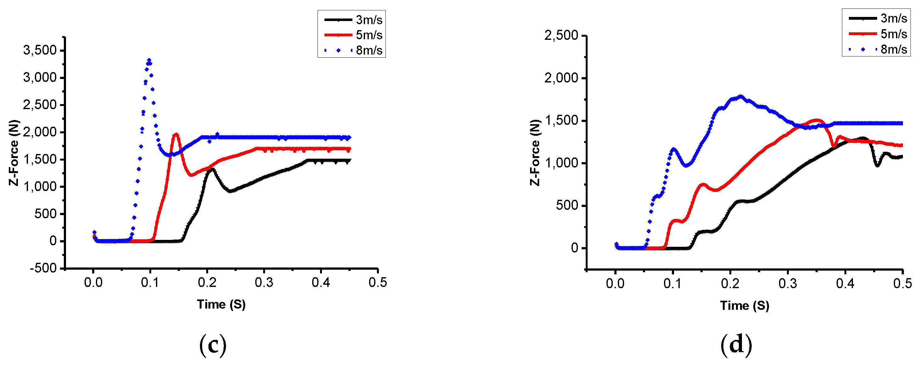
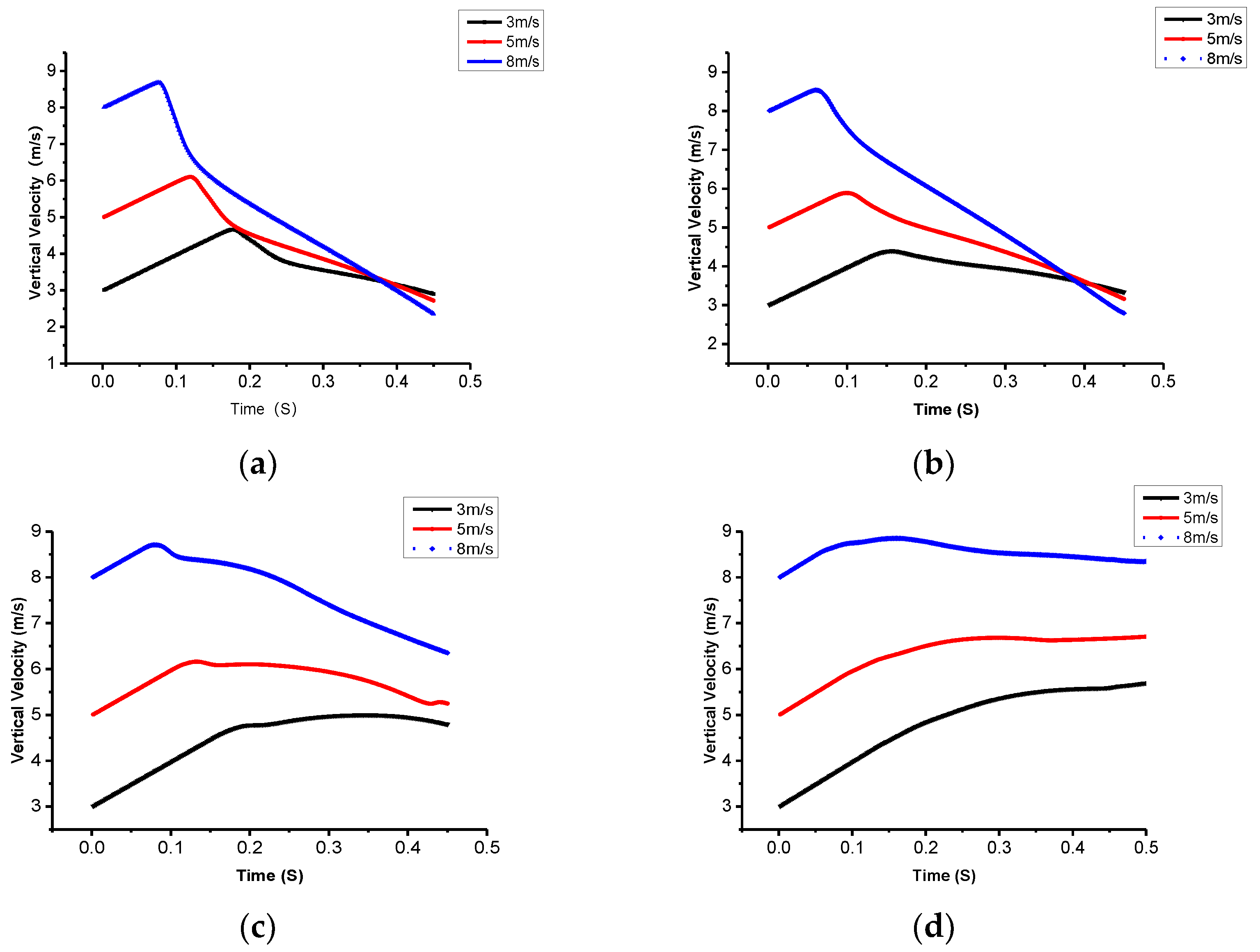
4.2. Variations of the AUH Water Entry Velocity

Figure 10a–d shows the speed changes under different immersion conditions. There was an initial acceleration process for a very short period because this is the free-falling motion of the AUH. The greater the initial velocity, the shorter the free-fall duration was; the greater the immersion angle, the shorter the free-fall duration was. Subsequently, as the AUH head entered the water, the velocity of the AUH decreased over time, and the greater the initial velocity, the greater the speed reduction. For instance, when the immersion angle of the AUH was at 30° and the AUH hull was completely immersed in water, the velocity reduced by 7.0, 4.3, and 2.7 m/s at 8, 5, and 3 m/s, respectively. The smaller the immersion angle, the greater the maximum vertical velocity that could be achieved. The larger the immersion angle, the smaller the vertical velocity change was, and the AUH quickly stabilized.

4.3. Maximum Load Analysis

Figure 11 shows the peak values of the impact surge loads on the AUH at different immersion angles. At the same angle, the initial velocity was directly proportional to the surge load. When the AUH immersion angle approached 30° and the initial velocity was 8 m/s, the load was up to 4000 N, which would seriously impact the safety of the AUH and would even cause electronic components to fail. At the same initial velocity, the smaller immersion angle caused a greater surge load to be experienced. Therefore, the results suggest that, to avoid a small immersion angle and a greater speed to decreasing the damage, the AUH structure should be mounted with precise sensors.

5. Conclusions

In this paper, viscous CFD two-phase flow simulations of a novel, vertical, axisymmetric AUH launched into water were carried out based on STAR-CCM+ VOF, UDF, and overlapping grid technologies. Numerical analyses of the axisymmetric impact forces on the disk-type AUH in the vertical plane were implemented with different water entry velocities and immersion angles. The deformable free surface and flow structure, from entry of the inclined AUH structure, were captured in a numerical tank, and the cavity around the AUH was found to form in a highly asymmetric way. The asymmetric degree of the formed cavity is highly correlated with the water entry velocity and immersion angle of the AUH.
In summary, the following conclusions are drawn:
(1)
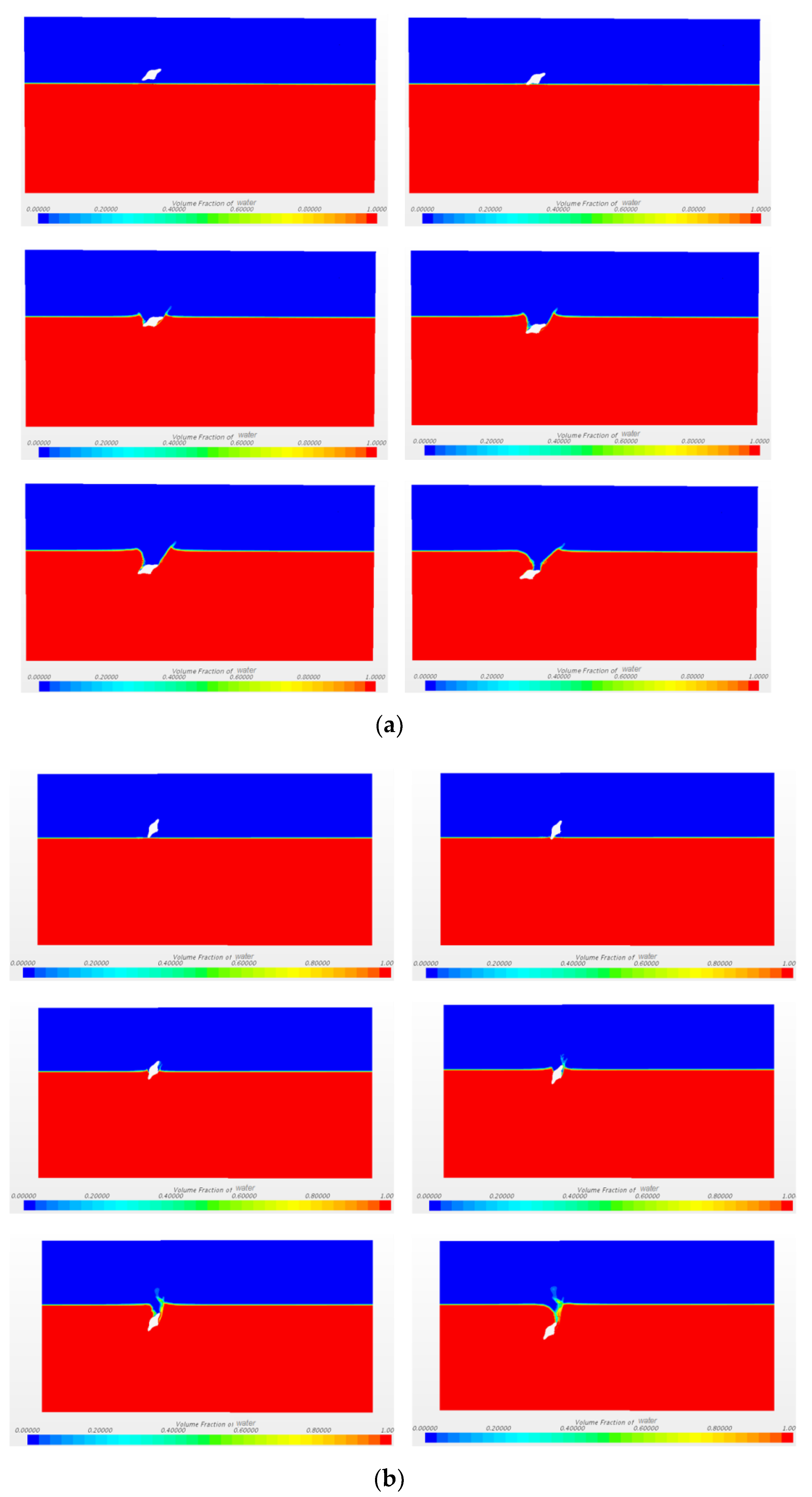
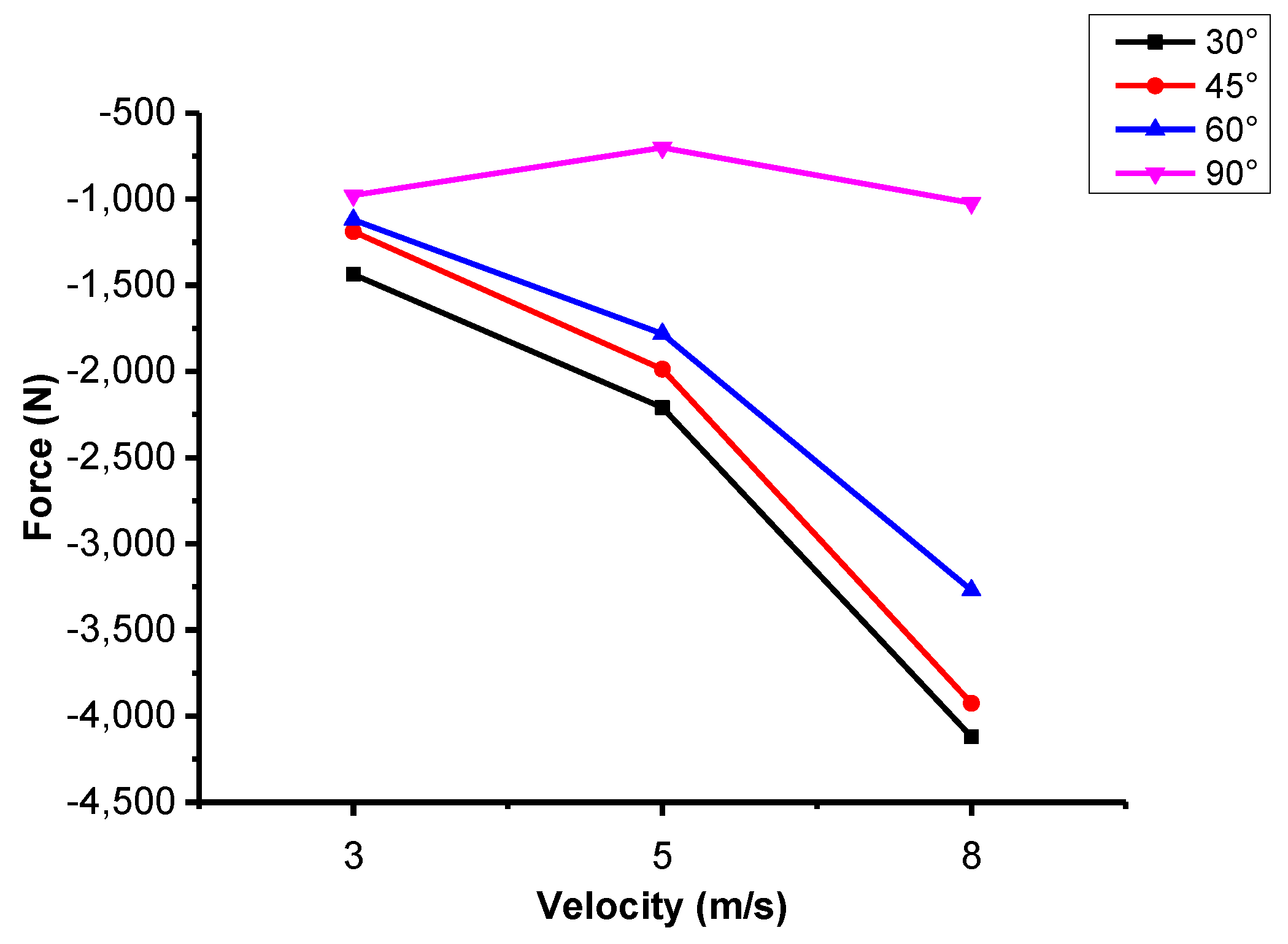
The total process of the AUH, with a traditional single-arm suspension or air-launched into the water, is accompanied by some significant phenomena such as surface uplift, splashing, asymmetrical cavity formation, and so on. The numerical stress analysis and maximum peak impact loads of the vertical axisymmetric hull body is emphasized in this paper. The variations of surge and heave loads versus initial velocities of 3, 5, and 8 m/s at different immersion angles of 30°, 45°, 60°, and 90° over time was studied.
(2)
While the AUH with an improved single-arm suspension was immersed into the water, a peak impact load occurred. As the water depth increased, the impact decreased until a stable value was reached. The impact load of the AUH decreased with an increasing water entry angle, and the greater the initial falling velocity of the AUH was, the greater was the load that was experienced. In these simulations, the maximum peak impact loads on the AUH in surge and heave appeared at the initial velocity 8 m/s and immersion angle 30°, approaching 4000 N and 10 4 N, respectively. These quantities shall be used as a reference for the structural strength design of the AUHs.
(3)
While the immersion angle of the air-launched AUH with a single-arm suspension immersed into the water decreased, the surge peak load increased. Thus, the dish-shaped AUH hull form should not have a small immersion angle into the water. Nevertheless, the silent phenomenon of acoustic transducers may appear when the water entry angle is 90°. In the trade-off study, these results suggest that the appropriate water entry immersion angle for the AUH should be 45°. The desired immersion angle will provide further design reference for air-launching transmitters of the AUHs.
Improvements will be made in future studies, including experiments with the same conditions as the numerical simulation. Based on a fabricated AUH, water entry impact force data on airborne-launched AUH, or on the air-launched AUHs using an improved single-arm suspension, will be collected in a sea trial to compare with the numerical simulation results. In addition, current and wave effects on launched AUHs will be considered in future work.

Author Contributions

Conceptualization, C.-W.C.; Data curation, Y.-F.L.; Formal analysis, Y.-F.L.; Funding acquisition, C.-W.C. and Y.-F.L.; Resources, C.-W.C.; Writing—original draft, C.-W.C. and Y.-F.L.; Writing—review & editing, C.-W.C. and Y.-F.L. The revision was done by C.-W.C. under the direction and supervision by C.-W.C.

Funding

This research was funded by the National Key R&D Program of China grant number 2017YFC0306100. And this research was funded by the National Science Foundation of China grant number 51409230. And this research was funded by the Zhejiang Zhoushan Science and Technology Project grant number 2018C81041.

Acknowledgments

The authors wish to thank the National Key R&D Program of China (Project Title: Autonomous Underwater Hovering-Vehicle, Project Number: 2017YFC0306100), the National Science Foundation of China (Project Title: Research on Vortex-Based Boundary Integral Method Estimating AUV Maneuverability Based on Euler–Rodriguez Quaternion Method, Project Number: 51409230), and the Zhejiang Zhoushan Science and Technology Project (Project Number: 2018C81041) for financially supporting the research on the hydrodynamic behavior of the AUHs.

Conflicts of Interest

The authors declare no conflicts of interest.

References

  1. Yamazaki, T. Status of Development for Deep-sea Mineral Resources. J. Jpn. Inst. Energy 2009, 88, 569–576. [Google Scholar]
  2. Leonard, J.J.; Bahr, A. Autonomous Underwater Vehicle Navigation. J. Ocean. Eng. Technol. 2010, 35, 663–678. [Google Scholar]
  3. Yi, R.; Hu, Z.; Lin, Y.; Gu, H.; Ji, D.; Liu, J.; Wang, C. Maneuverability design and analysis of an autonomous underwater vehicle for deep-sea hydrothermal plume survey. In 2013 OCEANS—San Diego; IEEE: San Diego, CA, USA, 2013; pp. 1–5. [Google Scholar]
  4. Fossen, T.I. Marine Control System, Guidance, Navigation and Control of Ships, Rigs and Underwater; Marine Cybernetics: Trondheim, Norway, 2002; p. 586. [Google Scholar]
  5. Phillips, A.B.; Turnock, S.R.; Furlong, M. The use of computational fluid dynamics to aid cost-effective hydrodynamic design of autonomous underwater vehicles. Proc. Inst. Mech. Eng. Part M J. Eng. Marit. Environ. 2010, 224, 239–254. [Google Scholar] [CrossRef]
  6. Chen, C.-W.; Jiang, Y.; Huang, H.-C.; Ji, D.-X.; Sun, G.-Q.; Yu, Z.; Chen, Y. Computational fluid dynamics study of the motion stability of an autonomous underwater helicopter. Ocean Eng. 2017, 143, 227–239. [Google Scholar] [CrossRef]
  7. Chen, C.-W.; Jiang, Y. Computational Fluid Dynamics Study of Magnus Force on an Axis-Symmetric, Disk-Type AUV with Symmetric Propulsion. Symmetry 2019, 11, 397. [Google Scholar] [CrossRef]
  8. Chen, Q.; Sun, R. Analysis of launch and recovery UUV model for submarine. Ship Sci. Technol. 2011, 33, 146–149. [Google Scholar]
  9. Zhang, H.L.; Deng, Z.Y.; Luo, Y.G. Development actuality of submarine launch and recovery system. Ship Sci. Technol. 2012, 34, 3–6. [Google Scholar]
  10. Sarda, E.I.; Dhanak, M.R. A USV-Based Automated Launch and Recovery System for AUVs. J. Ocean. Eng. Technol. 2017, 42, 37–55. [Google Scholar] [CrossRef]
  11. Yan, G.-X.; Pan, G.; Shi, Y.; Chao, L.-M.; Zhang, D. Experimental and numerical investigation of water impact on air-launched AUVs. Ocean Eng. 2018, 167, 156–168. [Google Scholar] [CrossRef]
  12. Techet, A.; Truscott, T. Water entry of spinning hydrophobic and hydrophilic spheres. J. Fluids Struct. 2011, 27, 716–726. [Google Scholar] [CrossRef]
  13. Truscott, T.T.; Epps, B.P.; Belden, J. Water Entry of Projectiles. Annu. Rev. Fluid Mech. 2014, 46, 355–378. [Google Scholar] [CrossRef]
  14. Zhao, C.; Wang, C.; Wei, Y.; Zhang, X.; Sun, T. Experimental study on oblique water entry of projectiles. Mod. Phys. Lett. B 2016, 30, 1650348. [Google Scholar] [CrossRef]
  15. Xia, W.; Wang, C.; Wei, Y.; Li, J. Experimental Study on Water Entry of Inclined Circular Cylinders with Horizontal Velocities. Int. J. Multiph. Flow 2019, 118, 37–49. [Google Scholar] [CrossRef]
  16. Nair, V.V.; Bhattacharyya, S. Water entry and exit of axisymmetric bodies by CFD approach. J. Ocean Eng. Sci. 2018, 3, 156–174. [Google Scholar] [CrossRef]
  17. WANG, Y.H.; SHI, X.H.; WANG, P.; WANG, S.W.; ZHAO, J.R. Modeling and Simulation of Oblique Water-Entry of Disk Ogive. Torpedo Technol. 2008, 16, 14–17. [Google Scholar]
  18. QIU, H.Q.; YUAN, X.L.; WANG, Y.D.; LIU, C.L. Simulation on Impact Load and Cavity Shape in High Speed Vertical Water Entry for an Axisymmetric Body. Torpedo Technol. 2013, 21, 161–164. [Google Scholar]
  19. Qi, D.; Feng, J.; Xu, B.; Zhang, J.; Li, Y. Investigation of water entry impact forces on airborne-launched AUVs. Eng. Appl. Comput. Fluid Mech. 2016, 10, 475–486. [Google Scholar] [CrossRef]
  20. Shi, Y.; Pan, G.; Huang, Q. Water entry impact cushioning performance of mitigator for AUV. In Oceans 2017–Aberdeen; IEEE: Aberdeen, UK, 2017. [Google Scholar]
  21. Ma, Q.P.; He, C.T.; Wang, C.; Wei, Y.J.; Lu, Z.L.; Sun, J. Experimental investigation on vertical water-entry cavity of sphere. Explos. Shock. Waves 2014, 34, 174–180. [Google Scholar]
  22. Nouri, N.M.; Zeinali, M.; Jahangardy, Y. AUV hull shape design based on desired pressure distribution. J. Mar. Sci. Technol. 2016, 21, 203–215. [Google Scholar] [CrossRef]
  23. Sodja, J. Turbulence Models in CFD; University of Ljubljana: Ljubljana, Slovenia, 2007; pp. 1–18. [Google Scholar]
  24. Sakthivel, R.; Vengadesan, S.; Bhattacharyya, S.K. Application of non-linear k-e turbulence model in flow simulation over underwater axisymmetric hull at higher angle of attack. J. Nav. Arch. Mar. Eng. 2011, 8, 149–163. [Google Scholar] [CrossRef]
  25. Nematollahi, A.; Dadvand, A.; Dawoodian, M. An axisymmetric underwater vehicle-free surface interaction: A numerical study. Ocean Eng. 2015, 96, 205–214. [Google Scholar] [CrossRef]
  26. Hirt, C.W.; Nichols, B.D. Volume of fluid (VOF) method for the dynamics of free boundaries. J. Comput. Phys. 1981, 39, 201–225. [Google Scholar] [CrossRef]
  27. Chow, P.; Cross, M.; Pericleous, K. A natural extension of the conventional finite volume method into polygonal unstructured meshes for CFD application. Appl. Math. Model. 1996, 20, 170–183. [Google Scholar] [CrossRef]
  28. Jinxin, Z.; Yumin, S.; Lei, J.; Jian, C. Hydrodynamic performance calculation and motion simulation of an AUV with appendages. In Proceedings of the 2011 International Conference on Electronic & Mechanical Engineering and Information Technology, Harbin, China, 12–14 August 2011; pp. 657–660. [Google Scholar]
Figure 1. Conceptual design of the disk-type autonomous underwater hovering vehicle (AUH).
Symmetry 11 01100 g001
Figure 2. Conventional launching and recovery system of a single-arm crane.
Symmetry 11 01100 g002
Figure 3. ZJU (Zhejiang University) AUH physical prototype.
Symmetry 11 01100 g003
Figure 4. Earth-fixed and body-fixed coordinates.
Symmetry 11 01100 g004
Figure 5. Computational domain for a steady, incompressible, two-phase flow of water and air with a free surface.
Symmetry 11 01100 g005
Figure 6. Mesh generations of the two-phase flow and AUH; (a) mesh of computational domain; (b) mesh partition of the AUH surface.
Symmetry 11 01100 g006
Figure 7. Two-phase flow simulation of the AUH at an initial velocity of 3 m/s with different immersion angles of 30° and 60°. (a) Immersion angle: 30°, initial velocity: 3 m/s; (b) immersion angle: 60°, initial velocity: 3 m/s.
Symmetry 11 01100 g007
Figure 8. The variations of surge loads versus initial velocities of 3, 5, and 8 m/s at different immersion angles of 30°, 45°, 60°, and 90° over time. (a) Immersion angle: 30°; (b) immersion angle: 45°; (c) immersion angle: 60°; and (d) immersion angle: 90°.
Symmetry 11 01100 g008
Figure 9. The variations of heave loads versus initial velocities of 3, 5, and 8 m/s at different immersion angles of 30°, 45°, 60°, and 90° over time. (a) Immersion angle: 30°; (b) immersion angle: 45°; (c) immersion angle: 60°; and (d) immersion angle: 90°.
Symmetry 11 01100 g009aSymmetry 11 01100 g009b
Figure 10. The variations of falling velocity in heave versus initial velocity (water entry velocity: 4.34, 5.90, and 8.59m/s) and immersion angles over time. (a) Immersion angle: 30°; (b) immersion angle: 45°; (c) immersion angle: 60°; and (d) immersion angle: 90°.
Symmetry 11 01100 g010
Figure 11. Variations of surge loads versus velocity at different immersion angles.
Symmetry 11 01100 g011
Table 1. Main parameters of the disk-shaped AUH.
Main ParametersSymbolUnitQuantitative Values
Diameter of the hull L m 1.0
Height of the hull d m 0.45
WeightWKg136.45
Service speed v m s 1 0.5144~1.5432
Density of fresh water ρ water kg m 3 1000.00
The viscosity coefficient of freshwater movement γ r Pa∙s 8.887 × 10 4
Density of air ρ air kg m 3 1.00
Aerodynamic viscosity γ a Pa∙s 1.85508 × 10 5
Run length L r m 0.40
Reynolds number Re / 3.46 × 10 5

