Article

Deep Learning as a Tool for Automatic Segmentation of Corneal Endothelium Images

by
Karolina Nurzynska
Institute of Informatics, Department of Automatic Control, Electronics and Computer Science, Silesian University of Technology, 44-100 Gliwice, Poland
The article is solely my authorship.
Symmetry 2018, 10(3), 60; https://doi.org/10.3390/sym10030060
Submission received: 13 January 2018 / Revised: 28 February 2018 / Accepted: 2 March 2018 / Published: 6 March 2018
(This article belongs to the Special Issue Advances in Medical Image Segmentation)

Abstract

:
The automatic analysis of the state of the corneal endothelium is of much interest in ophthalmology. Up till now, several manual and semi-automatic methods have been introduced, but the need of fully-automatic segmentation of cells in the endothelium is still in search. This work addresses the problem of automatic delineation of cells in the corneal endothelium images and suggests to use the convolutional neural network (CNN) to classify between cell center, cell body, and cell border in order to achieve precise segmentation. Additionally, a method to automatically select and split merged cells is given. In order to skeletonize the result, the best-fit method is used. The achieved outcomes are compared to manual annotations in order to define the mutual overlapping. The Dice index, Jaccard coefficient, modified Hausdorff distance, and several other metrics for mosaic overlapping are used. As a final check-up, the visual inspection is shown. The performed experiments revealed the best architecture for CNN. The correctness and precision of the segmentation were evaluated on Endothelial Cell “Alizarine” dataset. According to the Dice index and Jaccard coefficient, the automatically achieved cell delineation overlaps the original one with 93% precision. While modified Hausdorff distance shows 0.14 pixel distance, proving very high accuracy. These findings are confirmed by other metrics and also supported by presented visual inspection of achieved segmentations. To conclude, the methodology to achieve fully-automatic delineation of cell boundaries in the corneal endothelium images was presented. The segmentation obtained as a result of pixel classification with CNN proved very high precision.

1. Introduction

The corneal endothelium is a monolayer of cells which has a big impact on the human vision. It is responsible to assure proper hydration of the eyeball and in consequence its transparency by providing sufficient amount of water [1]. This is achieved by a dense location of cells of hexagonal shape to fill the surface as much as possible. Since the cells do not reproduce [2], their number decreases due to natural processes or in consequences of injuries. When a cell dies, the adjoining cells, in order to assure full surface coverage, occupy its space, what results in cell shape change.
In medical applications, the modifications of cell number and shape are investigated as a measure of endothelial layer state. Most commonly the cell density [3], coefficient of variation [4], and hexagonality [5] measures are used. All of them are calculated on the bases of data acquired by confocal or specular microscopy and require manual annotation of the images, which is a time-consuming and tiresome activity. Therefore, an automatic solution for this task is sought. Such a method should allow to automatically detect cell borders and then describe the cell structure [6,7,8].
Figure 1 shows an example of the corneal endothelium image. Although it may seem trivial to automatically delineate the cells’ borders, the research addressing this problem for several decades had to face many obstacles, because the quality of images is usually poor with low contrast, blurred regions (especially those further from focus), and artifacts. The complexity of this issue resulted in a broad spectrum of suggested solutions, which exploited various aspects of computer vision domain.
The automatic segmentation with an application of watershed techniques and its variants was one of the first applied. For instance, [9] used marker-driven watershed as a means of segmentation, [10] incorporated a watershed into a binarization step followed by further transformation. Recently [11,12,13,14] presented the stochastic version of this method.
A different solution described in [15] is based on a set of mask operators which enable hexagon detection in noisy images, whereas [16] introduced a more general method built with morphological operators. The more researchers dealt with this problem, the more complex solutions were presented, as the obstacles were better defined. For example [17] used the Bayesian framework with the assumption of hexagonal cell shape in order to precisely determine the cell borders. Some additional improvement was gained also by a statistical description of the area [18].
There are also many other, complex methods which address this problem. In general, they distinguish three separate stages in the processing of corneal endothelium images: preprocessing, binarization, and optimization. Since we do not aim at a detailed review of possibilities but are interested to give the reader a brief idea how widely the domain was researched, only the main approaches are named here. The preprocessing stage aims at noise removal, for instance with filtering [19], and illumination compensation, which can be achieved by background averaging [20]. The binarization could be accomplished by employment of balloon snakes [21], snakelets [22,23], level sets [24], wavelets [25], or Voronoi diagram [26], etc. This solution may result in thick and inaccurate border representation, hence the optimization techniques were suggested in [27,28] or skeletonization with K3M algorithm was introduced [29].
Finally, the concept of neural networks for automatic cell border detection was widely discussed in the literature. First, [30] introduced this approach, but due to several imprecision, the outcome did not allow for automatic segmentation. A further improvement, with manual removal of incorrect borders and supplementing the lacking ones, was presented in [31]. Next, [32] developed another network which classified whether a pixel belongs to the cell body or a vertical, horizontal, or oblique boundary. [33] suggested very similar approach but used a convolutional neural network. Finally, [34] trained a feedforward network with statistical information about pixels, in order to classify whether they represent the border or cell body.
The aim of this article is to present a novel approach for automatic segmentation of the corneal endothelium images. A convolutional neural network tailored to deal with this problem was designed. In contrary to previous solutions, it aims at the detection of cell bodies, which when necessary may serve as a starting point for a normalization methods exploited in order to assure optimal border detection, that is generating a border of one pixel thickness and traversed in the darkest valley existing between two cells on the original image. Moreover, authors present a novel approach to detect merged cells and suggest an automatic solution to split them. It results in very precise segmentation and enabled the creation of a fully automatic system for endothelial cell representation. These methods are described in Section 2. The conducted experiments which evaluate the accuracy of endothelial images segmentation and its further processing are presented in Section 3. Finally, Section 4 summarizes this work.

2. Materials and Methods

2.1. Endothelial Images

A dataset Endothelial Cell “Alizarine” [32] presents the images of corneal endothelium taken from porcine eyes stained with alizarine (see Figure 1). It was used in experiments because the cell shapes and photograph characteristics are similar to one of the humans. The monochromatic images, which resolution is 768 × 576 were acquired by inverse phase contrast microscope (Chroma Technology Corp, CK 40, Windham, VT, USA) with 200× magnification and photographed with an analog camera (Sony, SSCDC50AP, Tokyo, Japan). The images are accompanied by manually drawn segmentation. The cell boundaries are denoted by regions of good image contrast (close to the focus), while the blurred regions on the edges are left without annotation. In consequence up to a quarter of each from 30 images is annotated. There are 232 cells detected in average (ranging from 188 to 388) with the average cell area of 272.76 pixels. This dataset is available at http://bioimlab.dei.unipd.it.

2.2. Training Set Preparation

The deep learning approach to machine learning is based on the assumption, that the number of training examples is large. Therefore, the original images are split into smaller patches of size N × N , which may overlap. It is constrained that a selected point, corresponding to the central pixel is characteristic for a class. The influence of sample size N is evaluated.
Following classes were distinguished using the manual annotation as a starting point:
  • Cell border class finds pixel which corresponds to cell border and then cuts the sample assuring that this pixel is placed as a central point of the patch.
  • Cell center class for each cell finds its mass-center and these coordinates are used to choose an appropriate pixel as a central point of the sample.
  • Cell body is an additional class, which assumes to describe data which are far from cell center but are not a border. In order to create the sample, which belongs to this set, a cell border was sampled, and points laying 5 pixels from it in a horizontal or vertical direction (chosen randomly) were denoted as a central point of a sample.
There are around 10,000 images in each class.

2.3. Convolutional Neural Network

The segmentation is performed with application of convolutional neural network (CNN), which was trained to classify between images presenting endothelial cell body or border. In this research several aspects concerning the network design as well as possible output generation were investigated.
Before we describe the architecture of used networks, some theoretical introduction takes place [35]. The basic operation of CNN is a convolution, which works on the input image I and a kernel K , which size M × M is much smaller than the resolution of image ( N × N ). It can be formalized as follows:
S ( i , j ) = ( I K ) ( i , j ) = m M n M I ( m , n ) K ( i m , j n )
Each convolutional layer is a set of kernels (which are called filters), which transform the input image into the activation maps S (one for each kernel). In order to assure that the activation map has the same size as in input data, a zero padding on the margins is applied. They have several interesting properties. First of all, they keep the weights which are learned by the network and share it for a whole image. It is possible, as each kernel is applied for each input image pixel using a moving window, making the kernel to have sparse interaction with whole input data. The size of the window is defined by the kernel dimensions, while the step can be parametrized in the network, however, in most cases, it is equal to 1. Next, such a kernel enables to work with features of various sizes, as the responsibility to detect complex and bigger samples is on the network depth side.
The activation map is further transformed with a nonlinear function, where some local detection of crucial features is performed. Usually, the rectified linear activation function (ReLu) is exploited:
x = max ( 0 , x )
which due to its simple formulation is computationally efficient. Moreover, it does not saturate in the positive region and converges faster than other functions (e.g. sigmoid, tanh) which has an impact of the numerical computation during the network learning by back-propagation with stochastic gradient descent methods.
The typical convolutional network layer ends with a pooling, which replaces the network response at some location with a cumulative information concerning also the neighborhood. In most cases, the max-pooling layer is suggested, which chooses the output of maximal value from the neighborhood of size usually equals to 2 with a stride also set to 2. This operation makes the CNN resistant to the small translation of input data. Moreover, strides larger than 1 reduce the spatial information resulting in more compact responses transferred for further layers. This not only makes the computation faster, as less data needs processing but also enables generalization and description of more complex objects by deeper layers of the network.
In order to prepare the network for a noisy data and some overlaps of objects which are to be recognized, a dropout technique is applied. This method removes from weights calculation a random number of connections which changes for each training pass. In the result, the weights in the final layer should be prone to some lacking information in the input and additionally should manage to give a correct answer basing on many input features.
The last layer of the network is a fully connected layer which is just a standard feed-forward network, where each neuron in one layer is connected with all others in the second layer. As we can see, here the sharing of parameters is not applied, hence a large number of weights is used to describe the model. The task of those weights is to discover the knowledge introduced on the entry in order to perform correct classification, which should be obtained as an output of this stage. Therefore, the number of neurons on the second layer corresponds to the number of classes which are recognized by a network.
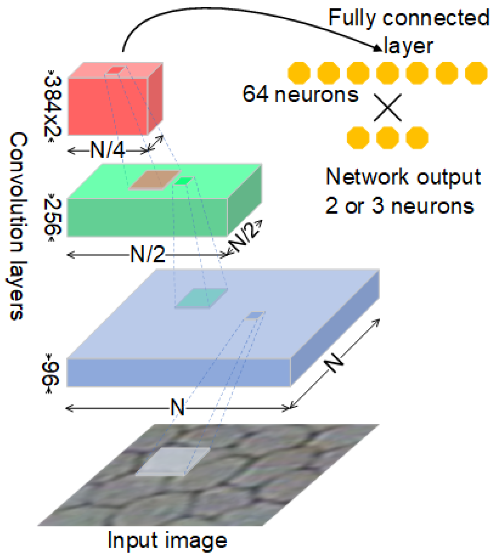
The network used in this work consists of four main layers: The first layer accepts an N × N × 1 image, which goes through a convolution stage, that has 96 filters of resolution 5 × 5 with padding. The acquired activations are transformed then with ReLu function, followed by cross-channel normalization ( 5 × 5 ) and finished by max-pooling transformation with stride 2. The second layer consists of similar set of processing units, where only the number of convolution filters is set to 256 and processing window resolution is set to 3 × 3 . The third layer keeps working using a window 3 × 3 and 384 filters for convolution stage which is followed by the ReLu nonlinear function. This pair is repeated twice and followed by another max-pooling transformation. Finally, the fourth layer consists of fully-connected network accepting 64 entries, ReLu function followed by dropout with 0.5 parameter value. Then the final fully-connected layer and softmax function are implemented. Figure 2 depicts the network architecture.

2.4. Segmentation Approaches

The method used to obtain image segmentation with employment of deep learning assumes to classify each pixel of the inspected image with the described CNN. This can be achieved by preparing patches of data for each pixel in the same spatial dimension as it was presented for training dataset preparation. In consequence, the pixels on image border (which size is N / 2 ) are not considered in segmentation.

2.5. Cell Splitting

Images segmented with the introduced methodology are not prone to some troubles. One of them is merged cells. It can be easily observed when for one cell body two or more cell centers were detected. Such case can be easily detected by computing merged cell index as:
MI ( c e l l ) = | { c : c C c B ( c e l l ) ϕ } |
where B is a set of cell bodies detected in the image, C is a set of cell centers, and c is one cell center. This index returns 0 when cell center was not detected, that may happen for very small cells. In most cases, the value should be 1 (as each cell body should have one cell center). Values greater than 1 suggest described problem and demand further attention.
When a cell body with several cell centers is detected, a distance function is evaluated to find the lacking cell boundaries. In result a distance map is computed for all pixels which are in the cell body.
DM ( p ) = p B ( c e l l ) μ C ( c e l l ) ) | | p μ | | 2
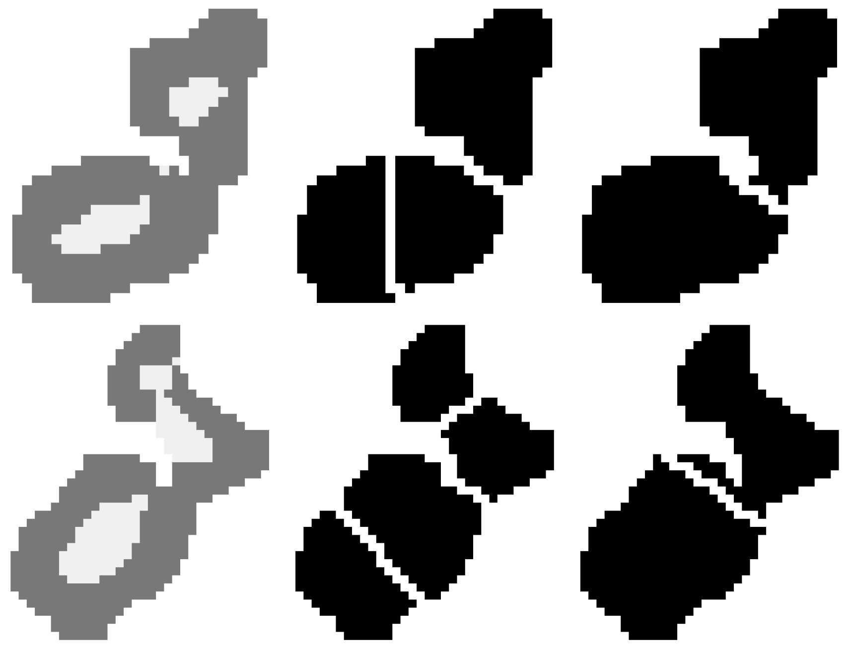
where p stands for coordinates of pixel belonging to the cell body, μ are the coordinates of mass center of a cell center, and | | · | | 2 is the Euclidean distance. This function takes maximal values in regions where lacking boundaries are placed, what enables splitting the cell body into non-overlapping regions with one cell center only. This simple approach proved to work better than watershed methods, which resulted in over-segmentation as depicted in Figure 3. As it is seen, the presented technique correctly found the segmentation, while the watershed created three or four cells in place where two existed.

2.6. Border Skeletonization

The cell borders resulting from the automatic segmentation are thick (in the meaning that there are places where more than one pixel denotes this delineation). This is not a problem when only the segmentation accuracy is considered, yet further analysis of cell’s shapes (like those suggested in [7]) could be affected by the boundary line thickness. Therefore further processing is necessary.
The problem to find an accurate delineation of cell boundaries is not a trivial task as it was argued in [36] and standard techniques of skeletonization are not sufficient. It was suggested [28] that a best-fit method solves all shortcomings and thus is exploited as a final skeletonization method applied for automatically obtained segmentation.

3. Results and Discussion

In order to obtain a fully automatic segmentation of images of the corneal endothelium, several issues were investigated. A classifier based on CNN was developed which address a two-class recognition between the cell border and cell center class. Although its result was promising, it was investigated, whether it is possible to obtain more precise outputs when additional class describing cell body is exploited. The accuracy here refers to the cell border delineation. All performed experiments enabled to detect the borders well, yet the issue of merged cells appeared which is discussed in further experiments. Finally, the accuracy of border delineation when skeletonization techniques are incorporated in final solution were investigated to analyze the usability of the suggested method in medical applications, where not the cell border are of interest, but the size and shape of the cells play the most important role.

3.1. CNN for Two-Class Problem

The motivation for this experiment was to check whether it is possible to prepare a classifier with CNN, which enables correct recognition between cell boundary and cell center. The input image resolution was set to 64 × 64 , which size was motivated by previous research concerning this problem conducted in [33]. The network was trained through 20 epochs with the learning rate set to 0.01 and mini-batch capacity of 64. The dataset consisted of around 20,000 of images, where 90% were used for training and 10% constituted a validation set. The backpropagation method used stochastic gradient descent.
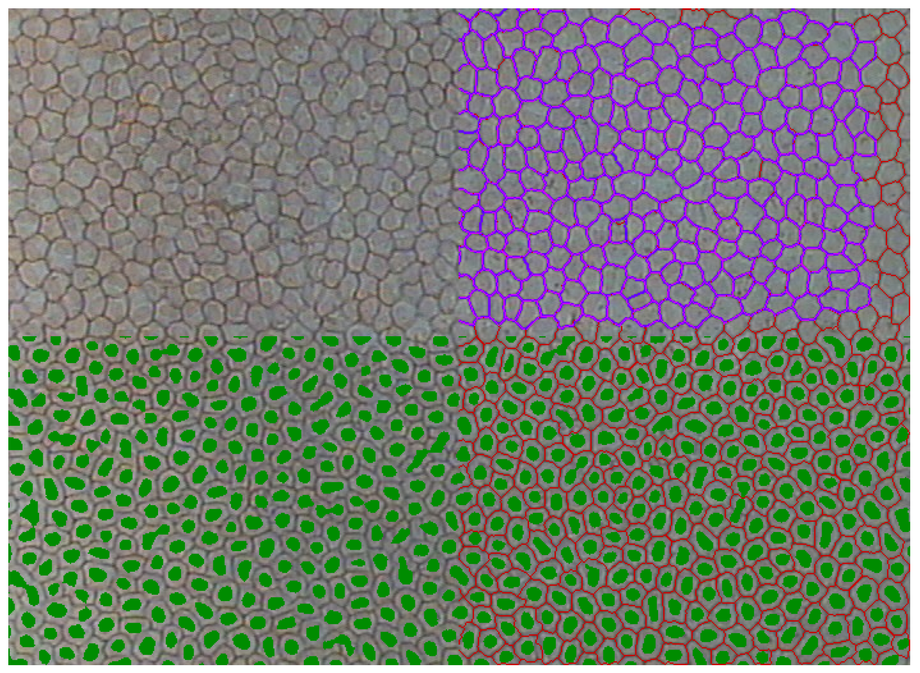
The performance of trained network was evaluated on the validation set, which proved 99.67% average accuracy for ten fold cross-validation. The visual inspection of segmentation outcomes proved good quality of cell center detection, yet show also very high imprecision in thin border detection. Figure 4 depicts the segmentation prepared by this approach. The presented image has uniform quality, hence similar results were observed in all its regions, that allow dividing the image into four parts showing different aspects of data segmentation. In the top-left corner, the original image is displayed. Pixels denoted with green color were classified as cell centers and are presented only in the bottom of the image. Pixels belonging to the border class are left transparent. As it is easily seen the cell centers are detected with very high accuracy, however, some centers go through a border and merge with other cell centers, that will result in the merged cell. The region of a boundary is well detected, yet is very thick. On the right side of the image, the red color denotes automatic delineation achieved when the best-fit algorithm was applied for this segmentation. Originally, the manual mask was prepared only for the sharpest part of the image, which is in the top-right corner. There the pink color describes where the automatic segmentation overlaps the manual one, while the blue color shows where only the manual segmentation was obtained. As it is easily seen this two masks significantly overlap each other. Moreover, it is worth pointing out that similar segmentation quality is achieved for the whole image, while in the training set only the part depicted by blue/pink color was labeled.
Since the number of filters applied by each convolution stage seems large, it was decided to repeat this experiment, with the number of filters scaled by factor 0.5. This idea was motivated by the general assumption, that deeper and narrow networks generalize better. Moreover, it seemed that the number of filters is excessive as in reality we are just looking for edges. The validation accuracy of this experiment was on the same level, but the segmentation proved to show more cell centers connected, thus was neglected.

3.2. CNN for Three-Class Problem

Although the segmentation of previous classification approach proved that it is possible to detect cell border regions with high fidelity, its thickness was not satisfactory. Therefore, an additional class which collects examples of regions close to the cell borders, but still not an exact cell boundary was designed and called a cell body.
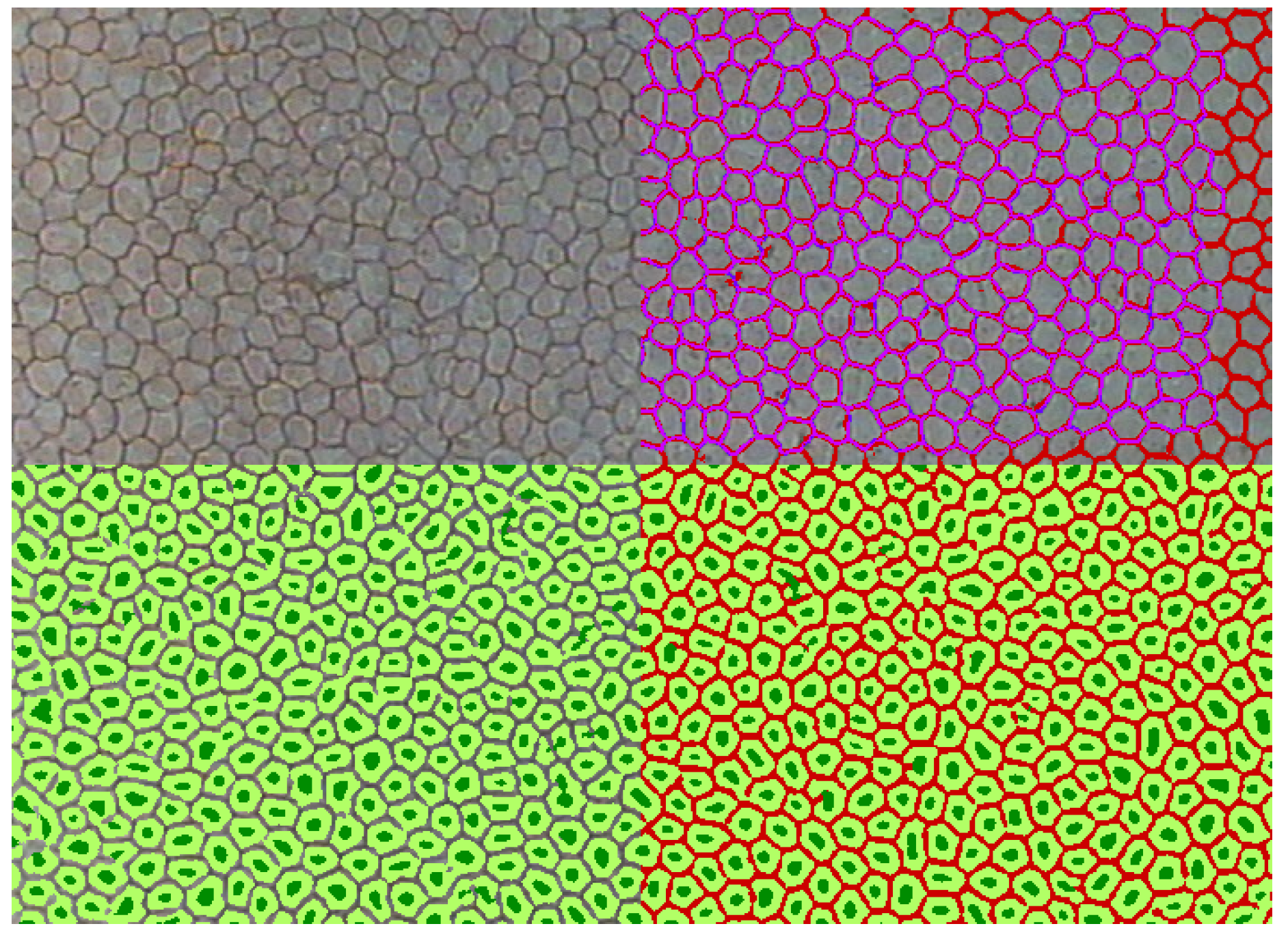
The CNN network used similar parameters for training as in the previous case and returned 84.85% correct classification accuracy for the validation set. However, the correct recognition ratio dropped significantly, the segmentation process showed very good quality as presented in Figure 5. This figure displays the same input data as was shown in Figure 4. Once again the dark green color indicates pixels assigned to cell center class, the light green shows where the cell body regions were detected. While transparent pixels in the bottom-left are for cell boundary. As we can see the cell centers become smaller, what resulted in the possibility of cell border detection in some cases, where the cells were merged last time. Next, the red color on the right side corresponds to the detected cell border without any improvements. As we can see it has a few pixels in its width, but it is comparable with the mask prepared manually. As it was in the previous case, the manual mask is denoted by blue color, while pink color is used to show the overlapping of manual and automatic segmentation. In general, the segmentation is precise, yet in some cases, the borders are broken. Having the information about the number of cell centers recognized within one cell body should be sufficient to solve both problems of broken delineation and merged cells. It is also worth underlining, that the automatic segmentation works very well for the whole image.
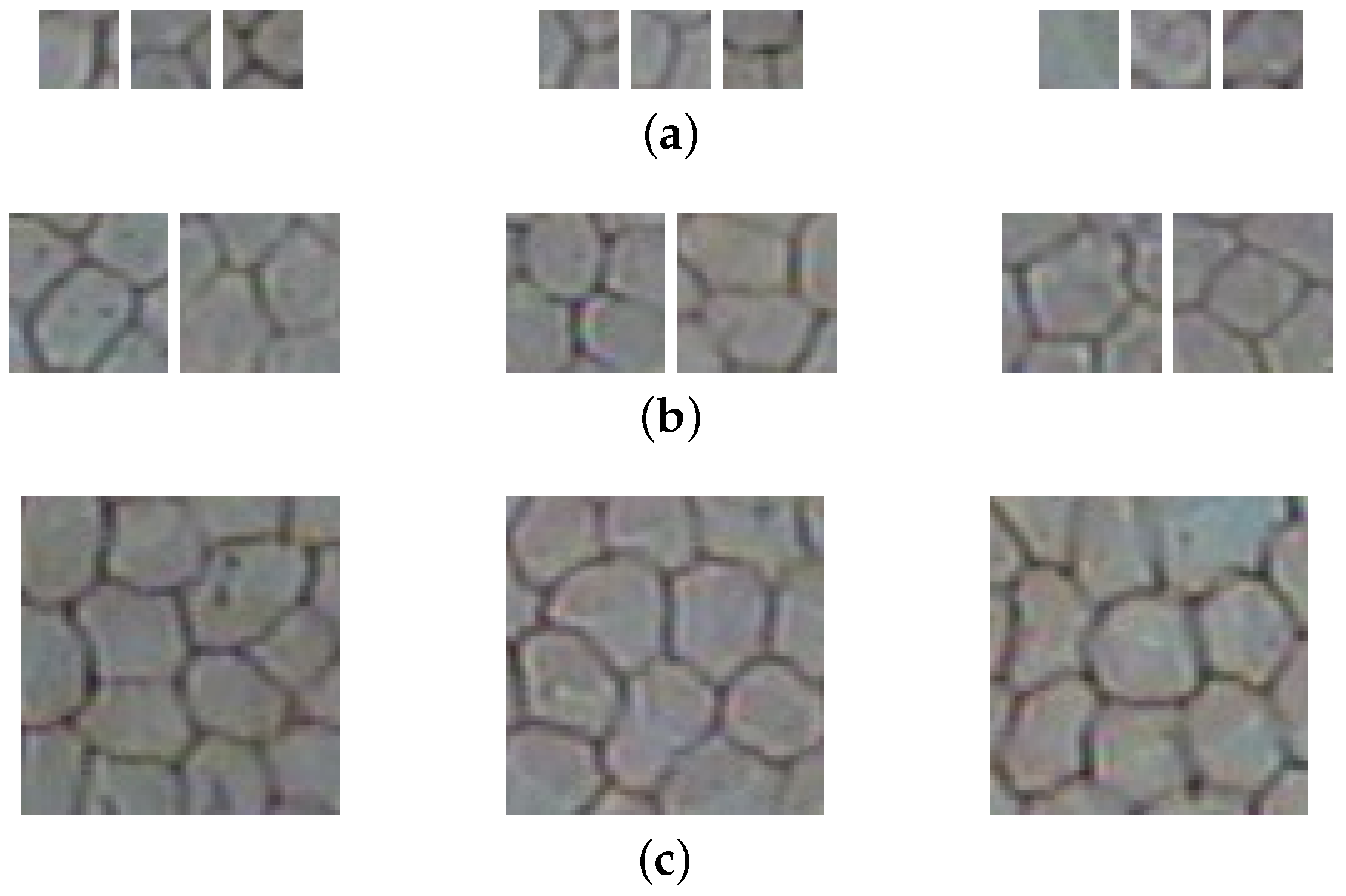
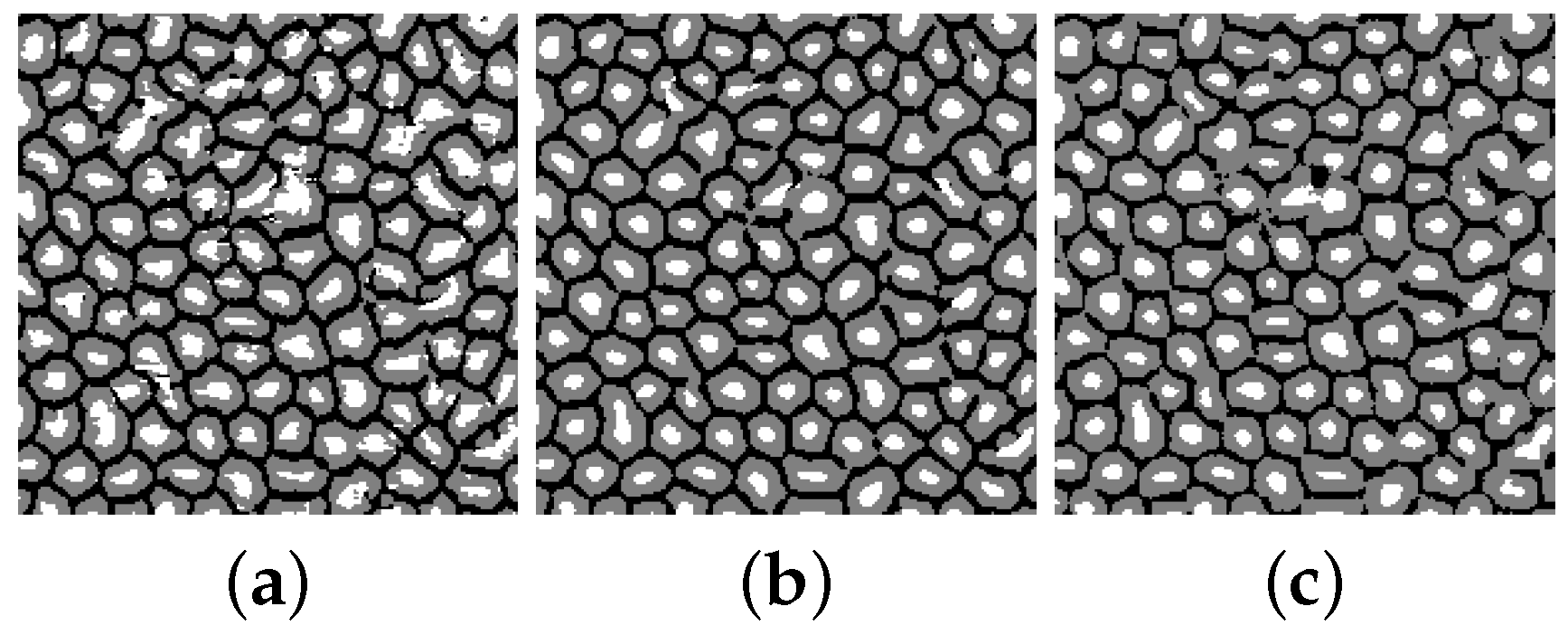
Another aspect of experiment preparation is the spatial resolution of the training sample (see examples presented in Figure 6). The region of interest is rather small when the border is analyzed (usually it should not be greater than 5 × 5 ). It grows larger with the cell center definition, but still the spatial resolution of 64 × 64 seems not justified. Therefore, two additional networks using 32 × 32 and 16 × 16 patches were evaluated. The change of input data resolution affects the network architecture. It was assumed that the 64 element vector fed for the last feed-forward layer should not be shorter. The number of pooling translation of the input data had got to change. In consequence for the network of N = 32 , the last pooling layer was removed from the CNN. While in the case of N = 16 the third and fourth layers were exchanged with a new one consisting of two convolutional kernels (of 256 and 384 filters respectively) followed by ReLu layer. Additionally, the resolution of convolutional and cross-channel filters were set to 3 × 3 . The visual inspection of examples presented in Figure 7 shows that when the sample size is small, it becomes difficult to correctly detect cell centers. This is probably the outcome, of variable cell size, and for larger cells, more pixels seems more adequate. In the contrary, when the sample size is large, it is more difficult to detect cell borders correctly. It might be, however, the result of the first convolution filter size, which in this case is 5 × 5 unlike 3 × 3 in other cases. The correct classification ratios obtained for ten times cross-validation approach are 86.37%, 87.54%, 87.65% calculated for sample size respectively 16, 32, and 64. Since the results are comparable for the larger patch approaches, it can be concluded that the best sample resolution is 32 × 32 due to its smaller size with similar classification accuracy—that supports the visual inspection finding.

3.3. Splitting Merged Cells

As mentioned earlier, sometimes the segmentation results in merged cells. In order to remove this problem, all cell bodies detected in the image are verified whether they depict one cell or are merged from several ones. In the second case, the cell splitting algorithm is applied. Figure 8 presents some examples of the splitting algorithm performance. As it is depicted in Figure 8a,b the suggested solution manages well merged cells nevertheless the input image quality. However, there are rare cases (see Figure 8c), where one cannot be sure whether it was correct to divide the cell, or maybe already the over-segmentation is present. This method cannot handle merged cells, which cell centers are also merged (see Figure 8d).

3.4. Segmentation Accuracy

From the medical point of view, it is not only important to delineate each cell of the corneal endothelium, but also to make it precisely, because the shape of the detected cell is used for calculation of parameters which describe the medical quality of this layer. It is difficult to find the objective measure, which enables comparison between two mosaics [36,37]. Therefore, here we investigate several approaches to better understand the quality of achieved results.
There are several measures, which allow computation of how much two binary objects overlap. They are used with a success in image processing domain and also in medicine where image information is considered. The most prominent metrics are Dice index [38] and Jaccard coefficient given with following formulas:
Dice = 2 · T P 2 · T P + F P + F N
Jaccard = T P T P + F N
where T P stands for true positive—those pixels which are the delineation in the computed set of cell borders and in the original mask; F P is false positive—elements which were recognized as a borders by mistake; and F N —these parts of image which should have been categorized as cell borders, but were wrongly marked as other class. Another method of mosaic comparison is by calculation of the distance which is between its two realizations, when pixels belonging to it are understood as a set of points P = p 1 , , p k and the number of points k may vary between compared objects. The modified Hausdorff distance (MHD) introduced by [39] is such a metric which enables calculation how far a set of A data is from the B . Its definition is given with following equations:
MHD ( A , B ) = max ( h d ( A , B ) , h d ( B , A ) )
where
h d ( A , B ) = 1 | A | a A min b B | | a b | | 2
An interesting overview for other metrics which can be applied to mosaic comparison is given in [40]. The author discusses several dissimilarity measures which can be applied to better describe achieved results: figure of merit (FOM), Yasnoff distance and also introduces his own measure, which we call Gavet. In these formulas B is assumed to be a perfect solution, while A is the mask prepared in the research.
FOM = 1 1 max ( | A | , | B | ) a A 1 1 + α ( min b B | | a , b | | ) 2
Yasnoff = 100 W a A ( min b B | | a , b | | ) 2
Gavet = log ( 2 ) W | ( A B ) \ ( A B ) |
where α = 1 and W is the number of pixels in the image.
Table 1 gathers average coefficients computed for three different sets: (I) manual mask vs. cell delineation resulting from classification; (II) manual mask skeletonized with best-fit vs. cell delineation resulting from classification; and finally (III) both the manual mask and cell delineation are transformed by best-fit before distance metric computation. These results reveal that application of best-fit normalization (case III) assures the very good quality of obtained segmentation as both the Dice index and Jaccard coefficient are above 93%, where repeatability above 80% is seen in medicine as a satisfactory one. In this setting, the average MHD distance becomes very small (0.14) what is in favor of a conclusion of very precise segmentation of the corneal endothelium cells. Other distance measures (FOM, Yasnoff, and Gavet) support this finding as in all cases their outcomes take the lowest values. Actually, in order to show how exact solutions were obtained the results are given with accuracy to two decimal places and a standard deviation.
Outcomes obtained for the case I expose, that the segmentation is also correct. Jaccard coefficient equal to 92% and reasonably small values of Yasnoff and Gavet support this finding. However significantly lower value obtained for Dice index means that many pixels were classified as false positive. Similarly larger values of MHD and FOM correspond to some problem of perfect fitting. These worsening of the outcome is due to the fact, that the automatic segmentation is thick. As we have shown the skeletonization applied in the case III is sufficient to remove this problem. Finally, when the original manual annotation is compared with the one prepared by the presented approach, the results are taking lower accuracy. Yet it is once again, a problem emerging from a thickness of the solution since the MHD did not increase significantly when compared to the case I, as well as the Yasnoff and Gavet also show better correspondence.
In order to better understand these findings, the additional test was performed. It used the manually annotated masks with applied best-fit to skeletonize them as one input. For comparison, the same mask was used but it was translated by one pixel vertically and horizontally. Such a slight change produced Dice index and Jaccard coefficient both equal to 26.72% and MHD equal to 1.80, while other measures also rise significantly: FOM equal to 0.40, Yasnoff equal to 0.02, and Gavet equal to 0.03. This experiment shows very well how much sensitive are each of exploited parameters on translation and that drawing two lines next to each other influences Dice, Jaccard, and MHD significantly, while has less influence on Yasnoff, Gavet and FOM. Consequently, basing on one segmentation performance only seems insufficient. It would be reasonable to base the description on a combination of outcomes rising from various approaches to delineation comparison. For instance, high values for Dice index assure that false positives are low, so we are close to the right choice of mosaic delineation. It can be also stated when Gavet, Yasnoff and FOM take low values and MHD returns small distance. On the other hand, when having the possibility to compare results obtained for precise segmentation (presented case III) and some worse realizations (cases I and II or results from translated experiments) one can gain the certainty, which metrics is the most appropriate.
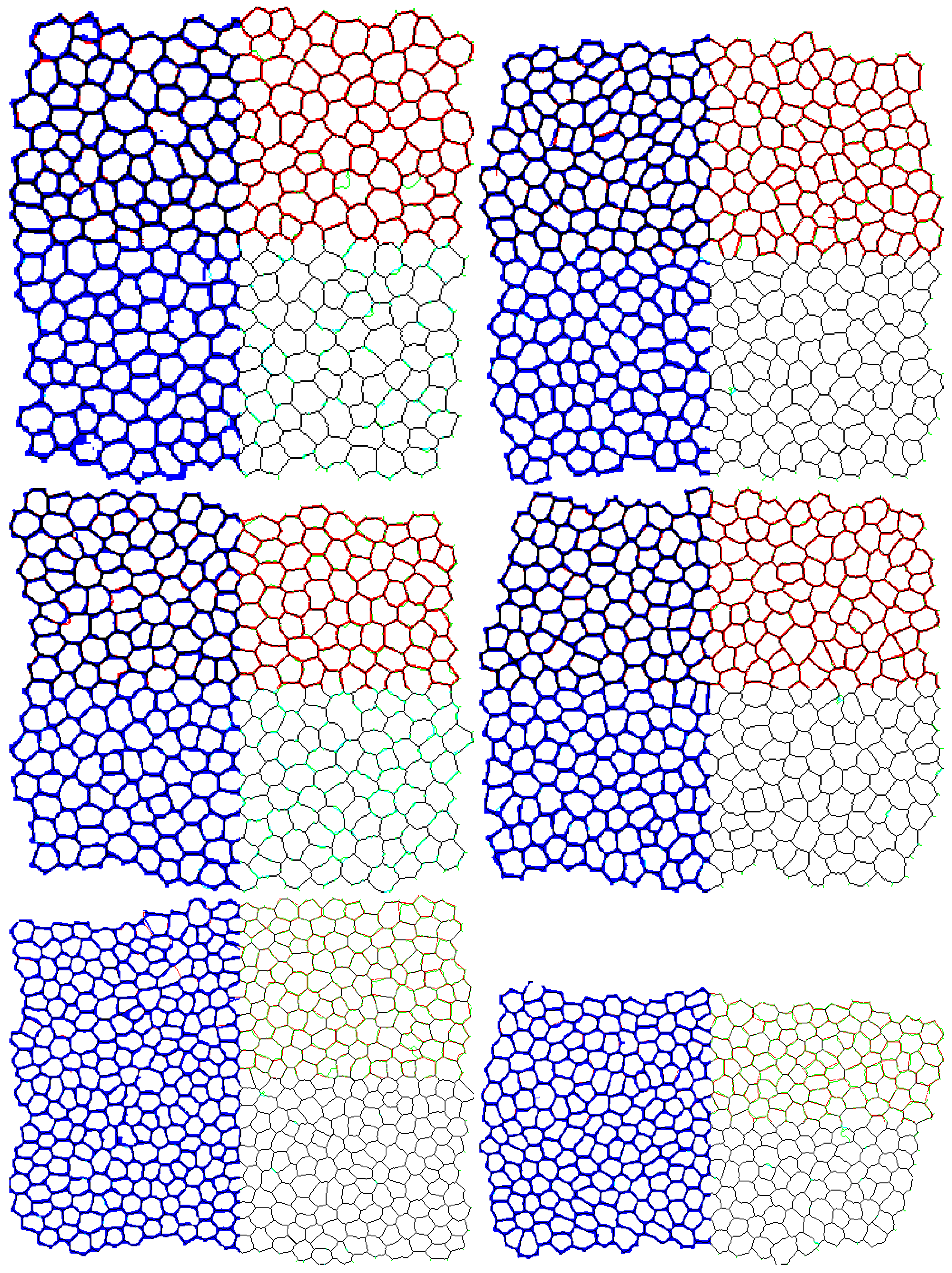
Figure 9 visualize the segmentation comparison. Each image is divided into four regions, where visual comparison of a considered segmentation outcomes is possible. The case I is depicted in the top-right corner, the case II is displayed in the bottom-right corner, while the case III is pictured in the bottom-left corner. The top-left corner matches original manual annotation with automatic segmentation transformed with the best-fit. The black line shows perfect repeatability of the achieved delineation, while colors show where which delineation did not overlap the other correctly—its meaning is given in figure caption. As it is easily seen, in all cases both approaches overlap what is presented by the black line which is visible all over the images. However, the best result is when both segmentations were normalized with the best-fit (the bottom-left corner), what supports the finding derived from analysis of segmentation features collected in Table 1.
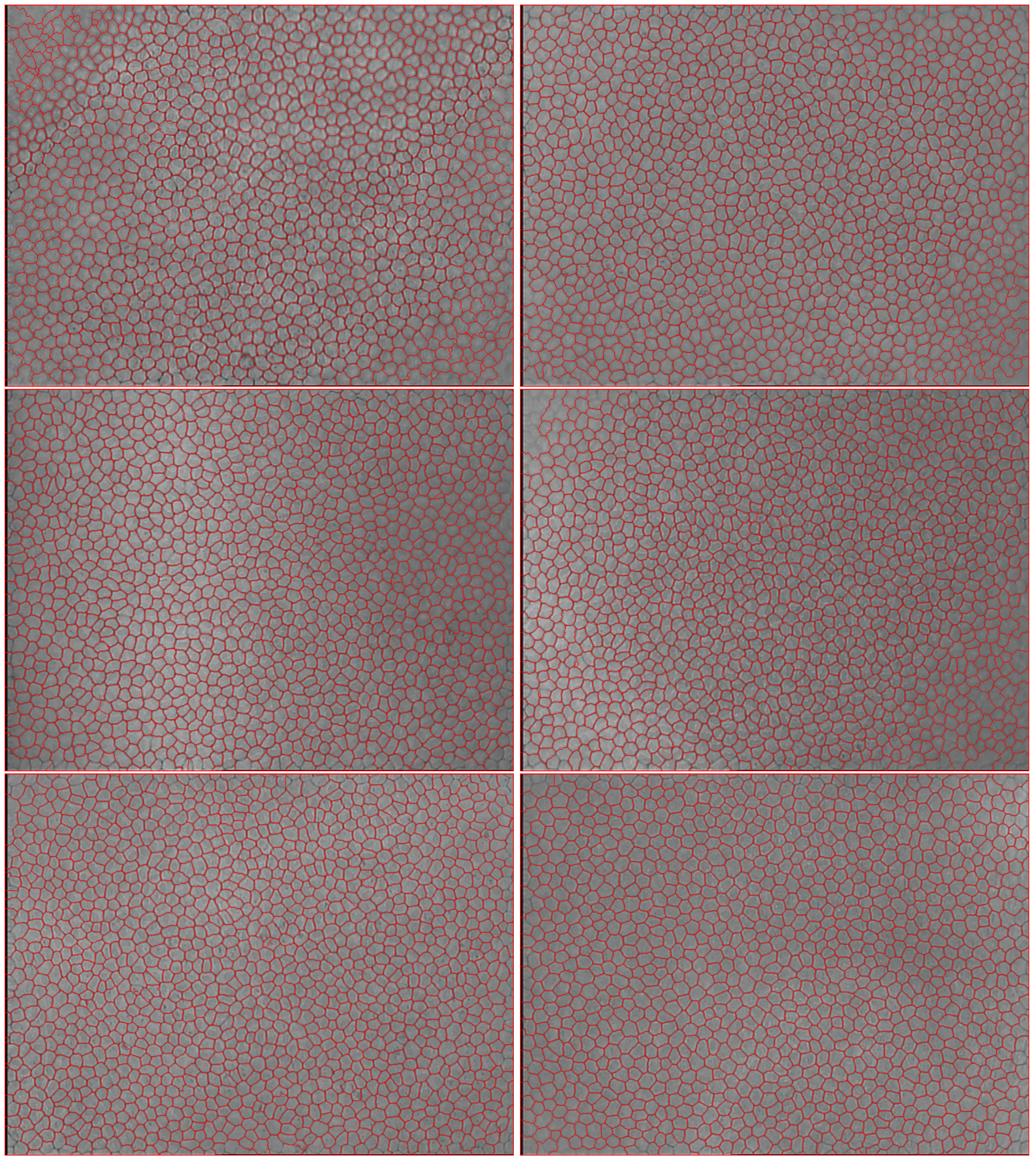
Figure 10 shows the result achieved by the proposed method when whole images from dataset underwent the segmentation. As one can see, the red line delineates cell borders accurately even in regions with a blurred image. However, when the input data deteriorates more significantly, as it is presented in the top-right corner of the first image, the delineation is still computed, however, it loses on smoothness and accuracy.

4. Conclusions

The aim of this work was to present a fully-automatic segmentation of cells in the corneal endothelium images. The presented method employs a CNN and classifies the pixels of input images into cell border, cell body, and cell center class. Its outcome is improved by splitting of merged cells and finally transformed with the best-fit skeletonization in order to obtain precise segmentation, which lines are of one pixel thickness.
The performed experiments revealed that the delineation achieved as a result of application of the CNN is satisfactory when only the two-class (cell border and cell center) problem is investigated. The resulting segmentation is characterized by thick borders; however, they may be normalized with the best-fit skeletonization. Exploiting CNN trained with three class shows better accuracy in cell border detection. It was also discovered that the best performance (considering cell border smoothness and noise) is for CNN trained with sample size N = 32 , where bigger samples make the delineation ragged and the smaller ones introduce noise by wrongly assigning pixels to cell center class. The suggested algorithm for splitting of merged cells proved useful. Finally, the automatic segmentation accuracy achieved 92% in therms of Jaccard coefficient with Dice index equal to 62% and MHD equal to 1.25 pixels. That was improved when data was additionally thinned by the best-fit method achieving, 93% for Jaccard coefficient and Dice index and 0.14 for MHD. Additional visual inspection of the repeatability of segmentation realization proved very high percent of overlapping regions. Finally, it is possible to achieve a highly precise delineation on the whole image, not only in the region where manual masks were annotated, what proves the great utility of the introduced solution in medicine.
In further research, some improvements are necessary. As the splitting method proved, it is sometimes difficult to state whether splitting is necessary or not. On the other hand, there are rare cases, where two cell centers are merged, which makes the splitting method useless. All of these problems should be addressed.

Acknowledgments

This work was supported by statutory funds for young researchers (BKM-509/RAU2/2017) of the Institute of Informatics, Silesian University of Technology, Poland.

Author Contributions

The article is solely my authorship.

Conflicts of Interest

The author declares no conflict of interest.

References

  1. Agarwal, S.; Agarwal, A.; Apple, D.; Buratto, L. Textbook of Ophthalmology; Jaypee Brothers, Medical Publishers Ltd.: New Dehli, India, 2002. [Google Scholar]
  2. Meyer, L.; Ubels, J.; Edelhauser, H. Corneal endothelial morphology in the rat. Investig. Ophthalmol. Vis. Sci. 1988, 29, 940–949. [Google Scholar]
  3. Rao, G.N.; Lohman, L.; Aquavella, J. Cell size-shape relationships in corneal endothelium. Investig. Ophthalmol. Vis. Sci. 1982, 22, 271–274. [Google Scholar]
  4. Doughty, M. The ambiguous coefficient of variation: Polymegethism of the corneal endothelium and central corneal thickness. Int. Contact Lens Clin. 1990, 17, 240–248. [Google Scholar] [CrossRef]
  5. Doughty, M. Concerning the symmetry of the hexagonal cells of the corneal endothelium. Exp. Eye Res. 1992, 55, 145–154. [Google Scholar] [CrossRef]
  6. Mazurek, P. Cell structures modeling using fractal generator and torus geometry. In Proceedings of the 2016 21st International Conference on Methods and Models in Automation and Robotics (MMAR), Miedzyzdroje, Poland, 29 August–1 September 2016; pp. 750–755. [Google Scholar]
  7. Nurzynska, K.; Piorkowski, A. The correlation analysis of the shape parameters for endothelial image characterisation. Image Anal. Stereol. 2016, 35, 149–158. [Google Scholar] [CrossRef]
  8. Nurzynska, K.; Kubo, M.; Muramoto, K.i. Shape parameters for automatic classification of snow particles into snowflake and graupel. Meteorol. Appl. 2013, 20, 257–265. [Google Scholar] [CrossRef]
  9. Vincent, L.M.; Masters, B.R. Morphological image processing and network analysis of cornea endothelial cell images. In Proceedings of the International Society for Optics and Photonics, San Diego, CA, USA, 1 June 1992; Volume 1769, pp. 212–226. [Google Scholar]
  10. Caetano, C.A.C.; Entura, L.; Sousa, S.J.; Tufo, R.E.A. Identification and segmentation of cells in images of donated corneas using mathematical morphology. In Proceedings of the XIII Brazilian Symposium on Computer Graphics and Image Processing, Gramado, Brazil, 17–20 October 2000; p. 344. [Google Scholar]
  11. Malmberg, F.; Selig, B.; Luengo Hendriks, C. Exact Evaluation of Stochastic Watersheds: From Trees to General Graphs. In Discrete Geometry for Computer Imagery; Lecture Notes in Computer Science; Barcucci, E., Frosini, A., Rinaldi, S., Eds.; Springer International Publishing: Berlin, Germany, 2014; Volume 8668, pp. 309–319. [Google Scholar]
  12. Bernander, K.B.; Gustavsson, K.; Selig, B.; Sintorn, I.M.; Luengo Hendriks, C.L. Improving the Stochastic Watershed. Pattern Recognit. Lett. 2013, 34, 993–1000. [Google Scholar] [CrossRef]
  13. Selig, B.; Malmberg, F.; Luengo Hendriks, C.L. Fast evaluation of the robust stochastic watershed. In Proceedings of the 12th International Syposium on Mathematical Morphology Mathematical Morphology and Its Applications to Signal and Image Processing, Lecture Notes in Computer Science, Reykjavik, Iceland, 27–29 May 2015; Volume 9082, pp. 705–716. [Google Scholar]
  14. Selig, B.; Vermeer, K.A.; Rieger, B.; Hillenaar, T.; Hendriks, C.L.L. Fully automatic evaluation of the corneal endothelium from in vivo confocal microscopy. BMC Med. Imaging 2015, 15. [Google Scholar] [CrossRef] [PubMed]
  15. Mahzoun, M.; Okazaki, K.; Mitsumoto, H.; Kawai, H.; Sato, Y.; Tamura, S.; Kani, K. Detection and complement of hexagonal borders in corneal endothelial cell image. Med. Imaging Technol. 1996, 14, 56–69. [Google Scholar]
  16. Serra, J.; Mlynarczuk, M. Morphological merging of multidimensional data. In Proceedings of the STERMAT 2000, Krakow, Poland, 20–23 September 2000; pp. 385–390. [Google Scholar]
  17. Foracchia, M.; Ruggeri, A. Corneal endothelium analysis by means of Bayesian shape modeling. In Proceedings of the 25th Annual International Conference of the IEEE Engineering in Medicine and Biology Society, Cancun, Mexico, 17–21 September 2003; pp. 794–797. [Google Scholar]
  18. Foracchia, M.; Ruggeri, A. Corneal Endothelium Cell Field Analysis by means of Interacting Bayesian Shape Models. In Proceedings of the 29th Annual International Conference of the Engineering in Medicine and Biology Society, Lyon, France, 22–26 Auguest 2007; pp. 6035–6038. [Google Scholar]
  19. Fabijańska, A.; Sankowski, D. Noise adaptive switching median-based filter for impulse noise removal from extremely corrupted images. IET Image Process. 2011, 5, 472–480. [Google Scholar] [CrossRef]
  20. Habrat, K.; Habrat, M.; Gronkowska-Serafin, J.; Piorkowski, A. Cell detection in corneal endothelial images using directional filters. In Image Processing and Communications Challenges 7; Advances in Intelligent Systems and Computing; Springer: Berlin, Germany, 2016; Volume 389, pp. 113–123. [Google Scholar]
  21. Dagher, I.; El Tom, K. WaterBalloons: A hybrid watershed Balloon Snake segmentation. Image Vis. Comput. 2008, 26, 905–912. [Google Scholar] [CrossRef]
  22. Charlampowicz, K.; Reska, D.; Boldak, C. Automatic segmentation of corneal endothelial cells using active contours. Adv. Comput. Sci. Res. 2014, 14, 47–60. [Google Scholar]
  23. Reska, D.; Jurczuk, K.; Boldak, C.; Kretowski, M. MESA: Complete approach for design and evaluation of segmentation methods using real and simulated tomographic images. Biocybern. Biomed. Eng. 2014, 34, 146–158. [Google Scholar] [CrossRef]
  24. Zhou, Y. Cell Segmentation Using Level Set Method. Master’s Thesis, Johannes Kepler Universitat, Linz, Austria, 2007. [Google Scholar]
  25. Khan, M.A.U.; Niazi, M.K.K.; Khan, M.A.; Ibrahim, M.T. Endothelial Cell Image Enhancement using Non-subsampled Image Pyramid. Inf. Technol. J. 2007, 6, 1057–1062. [Google Scholar]
  26. Brookes, N.H. Morphometry of organ cultured corneal endothelium using Voronoi segmentation. Cell Tissue Bank. 2017, 18, 167–183. [Google Scholar] [CrossRef] [PubMed]
  27. Piorkowski, A.; Gronkowska-Serafin, J. Towards Automated Cell Segmentation in Corneal Endothelium Images. In Image Processing and Communications Challenges 6; Advances in Intelligent Systems and Computing; Springer: Berlin, Germany, 2015; Volume 313, pp. 179–186. [Google Scholar]
  28. Piorkowski, A. Best-Fit Segmentation Created Using Flood-Based Iterative Thinning. In Image Processing and Communications Challenges 8. IP&C 2016; Advances in Intelligent Systems and Computing; Choraś, R.S., Ed.; Springer: Berlin, Germany, 2017; Volume 525, pp. 61–68. [Google Scholar]
  29. Saeed, K.; Tabȩdzki, M.; Rybnik, M.; Adamski, M. K3M: A universal algorithm for image skeletonization and a review of thinning techniques. Int. J. Appl. Math. Comput. Sci. 2010, 20, 317–335. [Google Scholar] [CrossRef]
  30. Hasegawa, A.; Itoh, K.; Ichioka, Y. Generalization of shift invariant neural networks: image processing of corneal endothelium. Neural Netw. 1996, 9, 345–356. [Google Scholar] [CrossRef]
  31. Foracchia, M.; Ruggeri, A. Cell contour detection in corneal endothelium in-vivo microscopy. In Proceedings of the 22nd Annual International Conference of the Engineering in Medicine and Biology Society, Chicago, IL, USA, 23–28 July 2000; Volume 2, pp. 1033–1035. [Google Scholar]
  32. Ruggeri, A.; Scarpa, F.; De Luca, M.; Meltendorf, C.; Schroeter, J. A system for the automatic estimation of morphometric parameters of corneal endothelium in alizarine red stained images. Br. J. Ophthalmol. 2010, 94, 643–647. [Google Scholar] [CrossRef] [PubMed]
  33. Katafuchi, S.; Yoshimura, M. Convolution neural network for contour extraction of corneal endothelial cells. In Proceedings of the 13th International Conference on Quality Control by Artificial Vision, Tokyo, Japan, 14 May 2017. [Google Scholar]
  34. Fabijanska, A. Corneal endothelium image segmentation using feedforward neural network. In Proceedings of the 2017 Federated Conference on Computer Science and Information Systems (FedCSIS), Prague, Check Republic, 3–6 September 2017; pp. 629–637. [Google Scholar]
  35. Goodfellow, I.; Bengio, Y.; Courville, A. Deep Learning; MIT Press: Cambridge, MA, USA, 2016. [Google Scholar]
  36. Piorkowski, A.; Nurzynska, K.; Gronkowska-Serafin, J.; Selig, B.; Boldak, C.; Reska, D. Influence of applied corneal endothelium image segmentation techniques on the clinical parameters. Comput. Med. Imaging Gr. 2017, 55, 13–27. [Google Scholar] [CrossRef] [PubMed]
  37. Gavet, Y.; Pinoli, J.C. Human visual perception and dissimilarity. Available online: http://spie.org/newsroom/4338-human-visual-perception-and-dissimilarity (accessed on 12 January 2018).
  38. Dice, L.R. Measures of the Amount of Ecologic Association Between Species. Ecology 1945, 26, 297–302. [Google Scholar] [CrossRef]
  39. Dubuisson, M.P.; Jain, A. A modified Hausdorff distance for object matching. In Proceedings of the 12th IAPR International Conference on Pattern Recognition, Jerusalem, Israel, 9–13 October 1994; Volume 1, pp. 566–568. [Google Scholar]
  40. Gavet, Y.; Pinoli, J.C. A Geometric Dissimilarity Criterion Between Jordan Spatial Mosaics. Theoretical Aspects and Application to Segmentation Evaluation. J. Math. Imaging Vis. 2012, 42, 25–49. [Google Scholar]
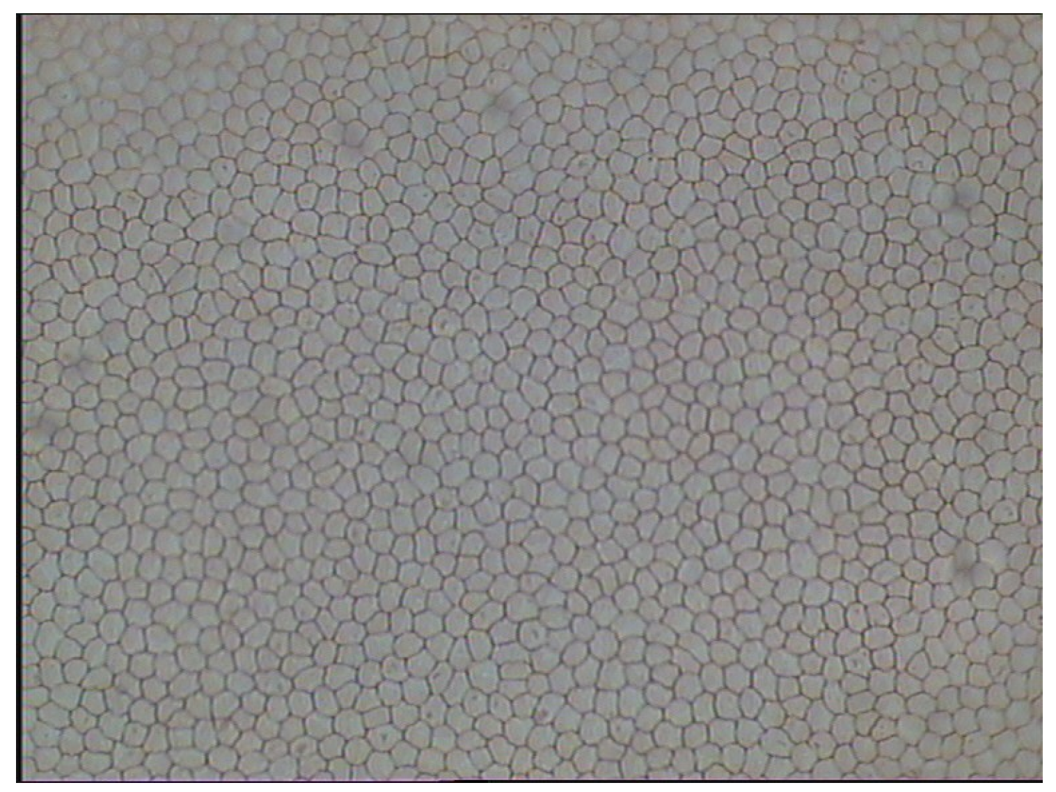
Figure 1. Image of exemplary corneal endothelium.
Symmetry 10 00060 g001
Figure 2. Visualization of convolutional neural network (CNN) architecture.
Symmetry 10 00060 g002
Figure 3. Cell division with proposed method and watershed. From the left: segmented cell, watershed segmentation, result of splitting method.
Symmetry 10 00060 g003
Figure 4. Visualization of achieved segmentation result when two classes were distinguished. Top-left: Original image. Bottom-left: green color denotes cell centers, while transparent regions denote cell borders. Bottom-right: red color marks cell borders delineation after application of best-fit for a prepared mask. Top-right: pink color shows where the automatic delineation overlaps the manual mask, blue is for the manual mask and red for the automatic one.
Symmetry 10 00060 g004
Figure 5. Visualization of achieved segmentation result when three classes were distinguished. Top-left: Original image. Bottom-left: intensive green color denotes cell centers, light green shows which pixels belong to cell body class, while transparent regions denote cell borders. Bottom-right: red color marks cell borders delineation—the same which is transparent on the left. Top-right: pink color shows where the automatic delineation overlaps the manual mask, blue is for the manual mask and red for the automatic one.
Symmetry 10 00060 g005
Figure 6. Exemplary training data of various resolutions (a) 16 × 16 ; (b) 32 × 32 ; (c) 64 × 64 . From the left: cell body, cell border, cell centre.
Symmetry 10 00060 g006
Figure 7. Segmentation outcomes for networks trained with a different spatial resolution of samples: (a) Side size 16; (b) Side size 32; (c) Side size 64. The white color is for cell center class; gray for cell body; and black for cell border.
Symmetry 10 00060 g007
Figure 8. Examples of the automatic splitting of cells which were merged. On the left original image. The result of automatic segmentation with classification is depicted in the middle (white color is for cell center, gray for cell body, and black for cell border). On the right results after cell splitting method was applied. (a) Correct examples for small cell; (b) Correct examples for blurred image; (c) Difficult to say. When concerning the shape it seems a correct segmentation, yet it is difficult to be sure since the image is blurred; (d) Impossible to split.
Symmetry 10 00060 g008
Figure 9. Visualization of repeatability of delineation obtained by automatic segmentation with and without best-fit. On the left side, the blue color depicts automatically achieved segmentation with presented method. On the right side, the green color depicts the automatic segmentation improved with the best-fit normalization. On the top, the red color represents the original manual annotation, while on the bottom in cyan the manual annotation transformed with the best-fit is represented. In case of both segmentation overlap, a black line is displayed.
Symmetry 10 00060 g009
Figure 10. Representative results of automatic segmentation achieved with the described method.
Symmetry 10 00060 g010
Table 1. Average measure (with standard deviation) computed to evaluate data segmentation accuracy.
ApproachIIIIII
Dice index 0.62 ± 0.16 0.51 ± 0.07 0.94 ± 0.07
Jaccard coefficient 0.92 ± 0.02 0.43 ± 0.03 0.94 ± 0.08
MHD 1.26 ± 0.85 1.29 ± 0.42 0.14 ± 0.13
FOM 0.30 ± 0.12 0.45 ± 0.13 0.04 ± 0.04
Yasnoff 0.04 ± 0.01 0.02 ± 0.01 0.01 ± 0.00
Gavet 0.03 ± 0.01 0.02 ± 0.01 0.00 ± 0.00