3.1. Time-Averaged and Transient Flow Structures
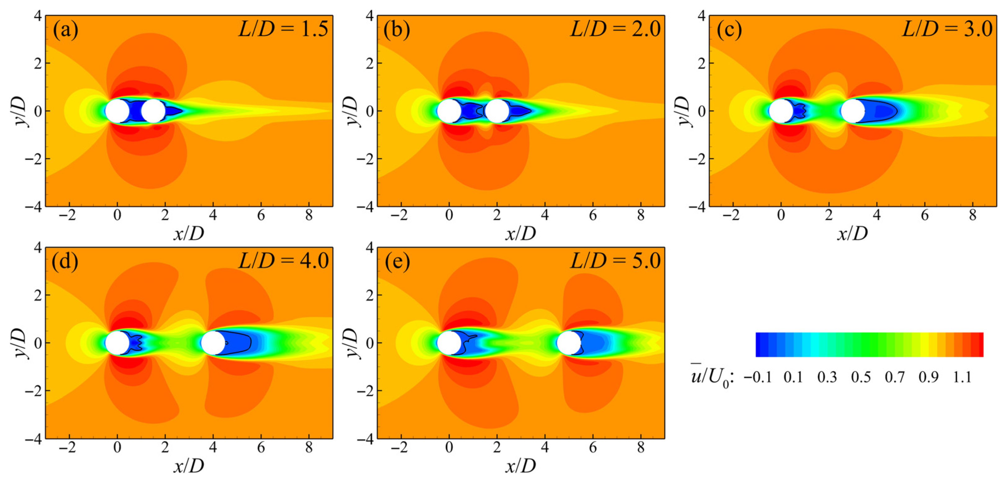
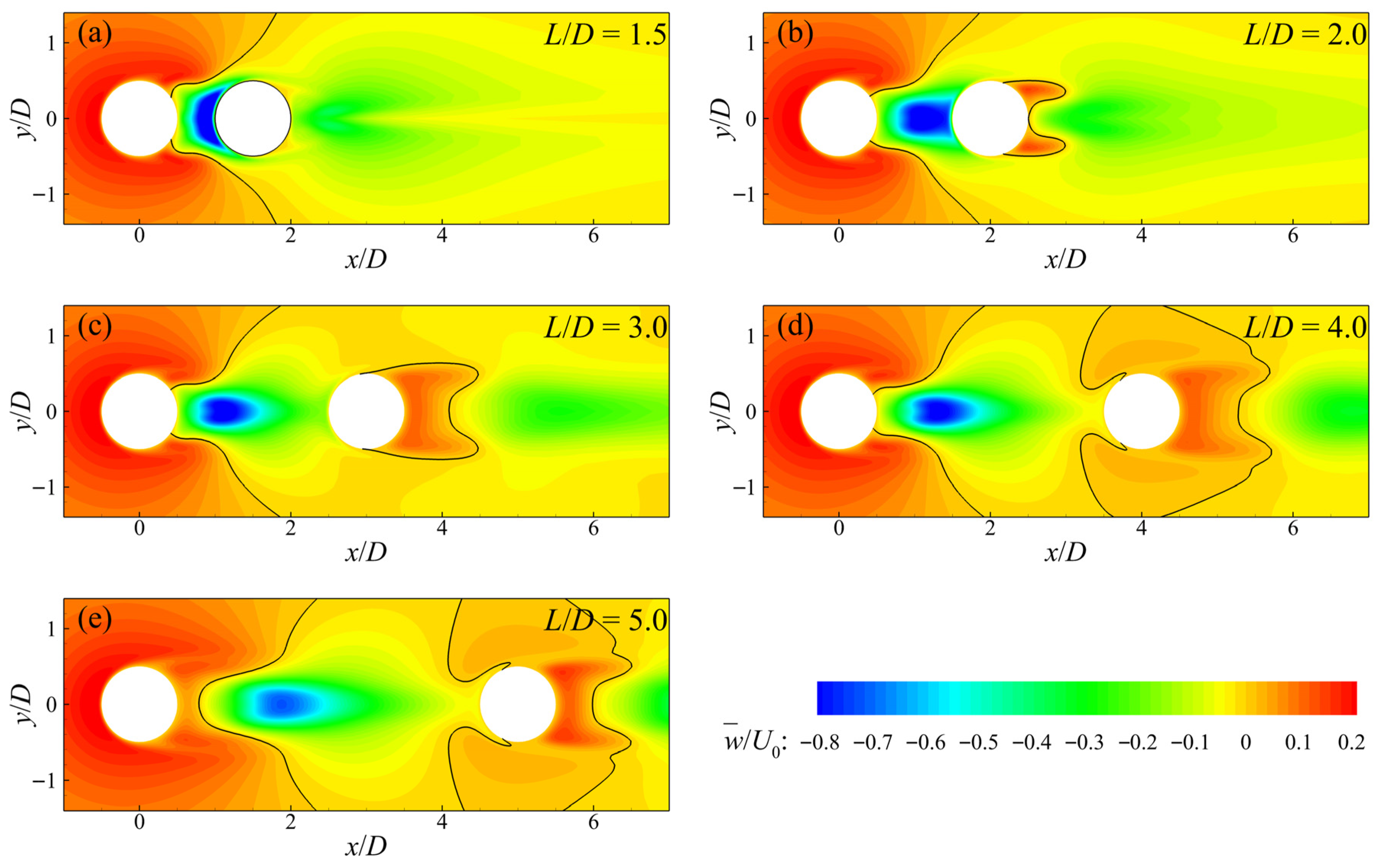
Figure 2 depicts the time-averaged streamwise velocity on the horizontal plane at half of the cylinder height, normalized by the free-stream velocity
U0, with the zero-velocity contour indicated by a black line to identify the recirculation regions. Overall, C1 and C2 consistently behave as an integrated body. The resulting velocity distribution resembles that observed in the flow past a single circular cylinder, with local acceleration regions forming on both lateral sides of the cylinders. The tandem-cylinder system thus tends to exhibit an elliptic-cylinder-like behavior with its major axis aligned with the streamwise direction. Accordingly, none of the cases considered belongs to the co-shedding regime. From a local perspective, distinct differences are observed between the cases of
L/
D = 1.5 and 2 and those of
L/
D = 3–5. In terms of the magnitude of lateral flow acceleration, the former two cases exhibit stronger blockage effects than the latter three, suggesting that they may fall into different flow regimes. For all five cases, recirculation occurs downstream of both C1 and C2. In the cases of
L/
D = 1.5 and 2, the width of the recirculation region between C1 and C2 remains nearly constant along the streamwise direction and is comparable to the cylinder diameter. This indicates that C2 is completely enveloped within the recirculation region of C1. This behavior is a typical feature of the extended-body regime. In contrast, for
L/
D = 3–5, the recirculation region fills the entire streamwise gap between C1 and C2 due to the blockage imposed by C2. Its width, however, decreases along the streamwise direction and then increases again as it approaches the downstream cylinder, as shown in
Figure 2c–e. This behavior indicates that these cases correspond to the reattachment regime, a conclusion that will be repeatedly confirmed in the subsequent analysis. The wake behind C2 is wider for
L/
D = 1.5 and 2 than for
L/
D = 3–5, aligning with the observations of Zeng et al. [
13] and Zhang et al. [
15].
The free end of a finite-length cylinder induces a downwash immediately downstream of the trailing edge, which interferes with the interaction of the separated shear layers on the lateral sides of the cylinder and alters the circumferential pressure distribution. This mechanism has been well documented for flow past a single finite-length cylinder [
18,
19,
42]. To illustrate the influence of the cylinder free end on the time-averaged velocity distribution of the tandem-cylinder system,
Figure 3 shows the normalized time-averaged streamwise velocity on a horizontal plane located 0.5
D below the cylinder top (
z = 9.5
D). It can be seen that, with increasing
L/D, the velocity distributions exhibit patterns that are markedly different from those on the
z = 5
D plane shown in
Figure 2. Only for
L/
D = 1.5 does the downstream cylinder remain completely immersed in the recirculation region of C1. For the other cases, the downstream cylinder is detached from the upstream recirculation region, and its upstream face is exposed to positive streamwise velocity. Both the upstream and downstream cylinders exhibit flow acceleration on their lateral sides, resembling the behavior of two isolated cylinders. This suggests that, on the
z = 9.5
D plane, the cases of
L/
D = 2–5 may fall into the co-shedding regime. The acceleration region around the downstream cylinder is, however, significantly smaller than that around C1. This indicates that the flow acceleration induced by the downstream cylinder is weakened by the shielding effect of C1. As the gap ratio increases, the influence of C1 on C2 gradually diminishes. For
L/
D = 2–5, recirculation regions form independently downstream of C1 and C2, with the recirculation length of C2 being, overall, slightly larger than that of C1. This behavior differs from observations for infinitely long tandem cylinders reported by Zeng et al. [
13], in which the recirculation region downstream of the cylinder C2 is always significantly smaller than that of the upstream cylinder. It is worth noting that, although the case of
L/
D = 1.5 remains in the extended-body regime on the
z = 9.5
D plane, the downstream cylinder already begins to exhibit a tendency to transition toward the reattachment regime.
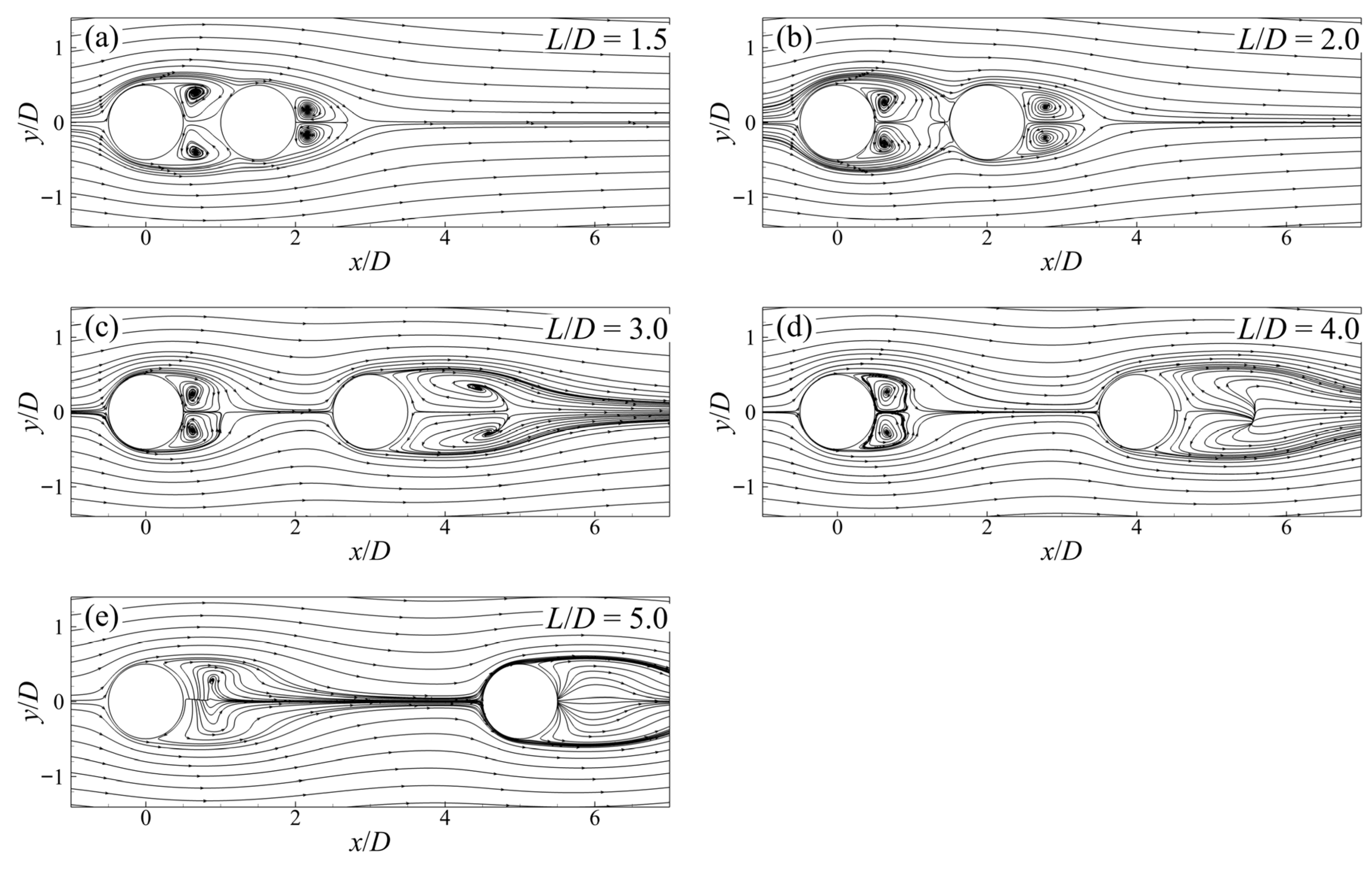
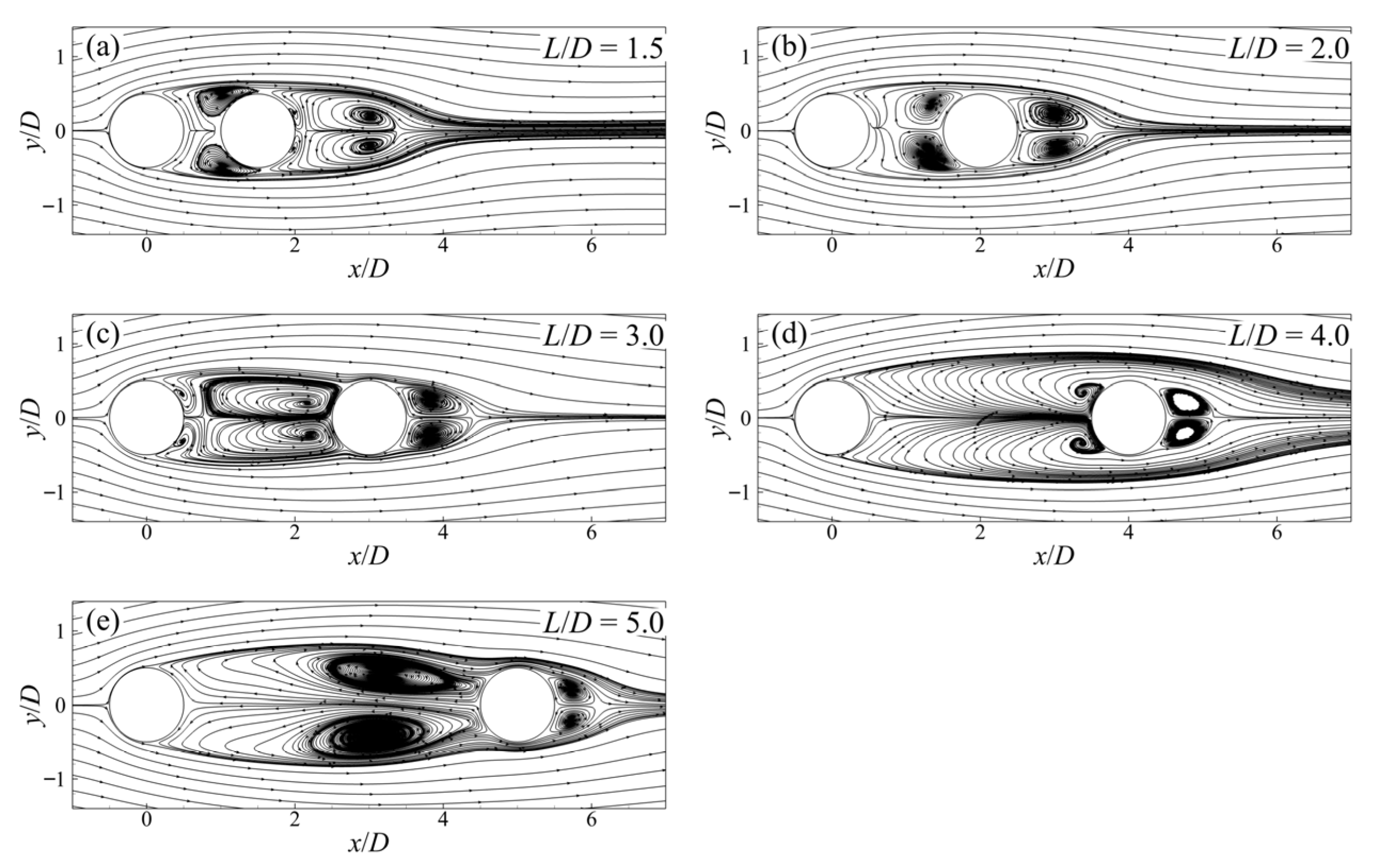
The two-dimensional time-averaged streamlines on the horizontal plane at half of the cylinder height are depicted in
Figure 4. For all cases, recirculation vortices form both in the gap region between the cylinders and downstream of the cylinder C2, and they are firmly attached to the surface of the downstream cylinder. For
L/
D = 1.5 and 2, the recirculation vortex occupies most of the gap region near the downstream side. It is stretched and twisted downstream along the surface of C2, while the vortex core remains approximately centered in the streamwise direction. When the system is in the reattachment regime, i.e., for
L/
D = 3–5, the recirculation vortex fills the entire gap region, and its core is markedly shifted toward the downstream cylinder. The overall size of the gap-region recirculation vortex increases with increasing
L/D. In contrast, the size of the recirculation vortex downstream of the downstream cylinder generally decreases as the gap ratio increases. These trends are consistent with the time-averaged velocity distributions shown in
Figure 2. For
L/
D = 1.5, because C2 is fully surrounded by the laterally separated shear layers of C1, its wake vortex is significantly larger than that of an isolated cylinder of the same diameter. In the cases of
L/
D = 1.5 and 3, secondary recirculation vortices are also observed on the cylinder surfaces, similar to those reported for flow past an isolated cylinder. Their locations, however, differ: for
L/
D = 1.5, they appear near the trailing edge of C2, whereas for
L/
D = 3, they occur near the trailing edge of C1.
Figure 5 illustrates the time-averaged recirculation patterns on the horizontal plane close to the cylinder free end (
z = 9.5
D). Unlike the gap-region recirculation vortices attached to C2 observed in
Figure 4, the gap-region recirculation vortices on the
z = 9.5
D plane are anchored to the trailing edge of the upstream cylinder. Only for
L/
D = 1.5, owing to the limited gap length, does the recirculation vortex still occupy the entire gap region. For
L/
D = 2–4, recirculation vortices form separately downstream of C1 and C2, behaving similarly to those behind isolated cylinders. This observation agrees with the recirculation patterns by Zeng et al. [
14] in the co-shedding regime. The sizes of the recirculation vortices downstream of C1 for
L/
D = 3 and 4 are comparable and slightly smaller than that for
L/
D = 2. For
L/
D = 5, the presence of vertical vortical structures interferes with the formation of horizontal-plane recirculation vortices, resulting in pronounced distortion of the two-dimensional streamlines. The differences in the time-averaged recirculation patterns between
Figure 4 and
Figure 5 further demonstrate that the wake-regime classification of the tandem-cylinder system varies along the vertical direction.
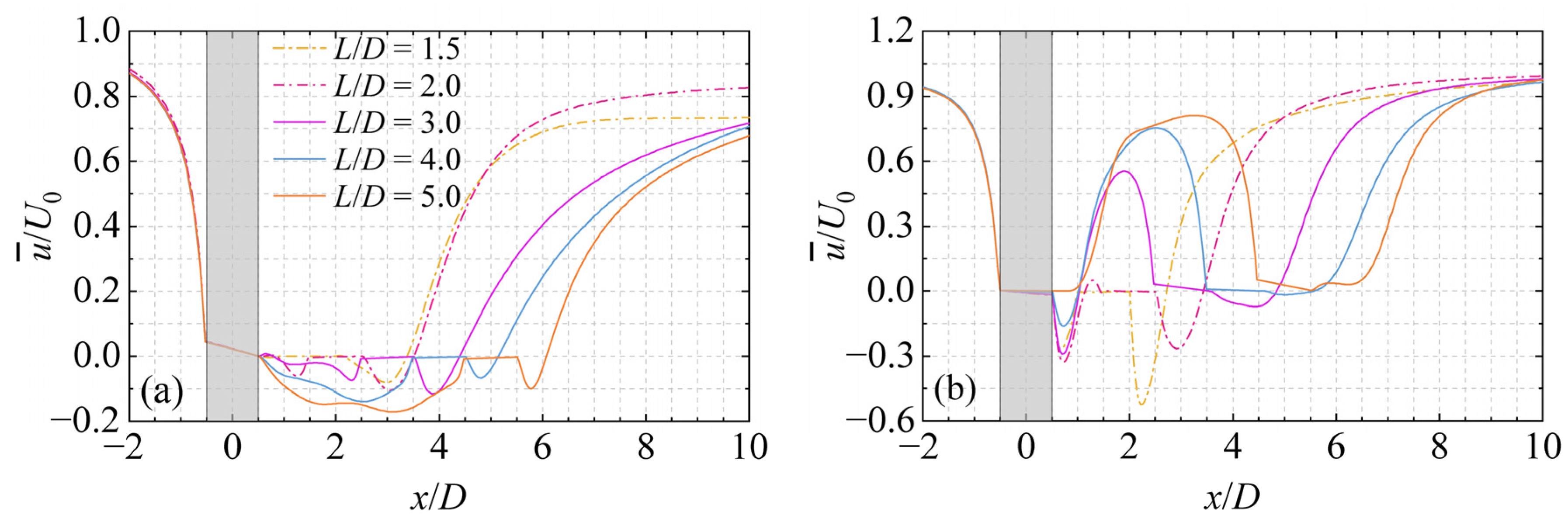
To further quantify the wake velocity recovery and the effects of the gap ratio,
Figure 6 presents the centerline distributions of the time-averaged streamwise velocity on the horizontal planes at
z = 5
D and
z = 9.5
D. In the upstream region of the tandem-cylinder system, compared with the
z = 5
D plane, the onset of streamwise velocity decay on the
z = 9.5
D plane occurs farther downstream, but the decay rate is higher. On both horizontal planes considered, the streamwise velocity decay in the upstream region is independent of the gap ratio. In other words, the pressure distribution on the upstream face of C1 is not affected by the gap ratio. On the
z = 5
D plane, within the gap region, except for the case of
L/
D = 1.5, in which the flow remains nearly stagnant throughout the gap, all other cases exhibit pronounced reverse flow. The intensity of the reverse flow increases with increasing
L/D, with the maximum reverse velocity being −0.06
U0 at
L/
D = 2 and reaching −0.17
U0 at
L/
D = 5. Nevertheless, because the case of
L/
D = 2 still belongs to the extended-body regime, the region within approximately 0.5
D downstream of the trailing edge of the upstream cylinder remains nearly stagnant. The strongest reverse flow consistently occurs in the portion of the gap region close to the downstream cylinder. This observation aligns with the downstream-shifted vortex cores of the gap-region recirculation vortices observed in the time-averaged streamlines shown in
Figure 4. On the
z = 9.5
D plane, the situation is markedly different. Within the gap region, only the case of
L/
D = 5 does not exhibit negative velocities over the entire gap, while maintaining a nearly stagnant flow over a streamwise extent of about 0.5
D immediately downstream of the upstream cylinder. For the other cases, the streamwise extent of the reverse-flow region downstream of C1 is nearly identical, approximately 0.5
D. Downstream of the reverse-flow region within the gap, the streamwise velocity rapidly recovers and then decreases again as it approaches the downstream cylinder, owing to the blockage imposed by C2. The maximum positive streamwise velocity within the gap increases with increasing
L/D, because larger gap ratios provide a longer distance for streamwise velocity recovery. The presence of positive streamwise velocity within the gap is one of the characteristic features distinguishing the co-shedding regime from the reattachment regime. In the wake of C2, the maximum reverse velocity decreases with increasing
L/D. At
L/
D = 4, the reverse velocity approaches zero, and at
L/
D = 5, the reverse flow disappears completely, which agrees with the absence of a recirculation vortex in
Figure 5e. Because the case of
L/
D = 1.5 remains in the extended-body regime, appreciable reverse flow persists throughout the gap region and downstream of C2.
The streamwise extent of the recirculation vortices observed in
Figure 4 and
Figure 5 can be quantified by the recirculation length
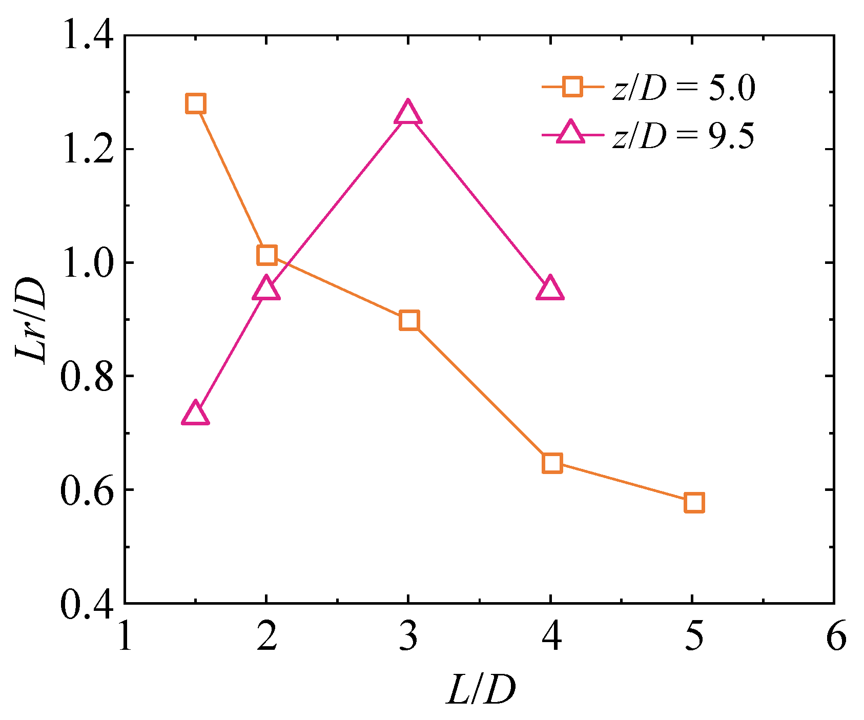
Lr. It is defined as the length along the wake centerline downstream of the cylinder over which the time-averaged streamwise velocity remains negative.
Figure 7 shows the dependence of the recirculation length downstream of the cylinder C2 on the gap ratio
L/D. As noted earlier, on the
z = 5
D plane, the recirculation region downstream of C1 fills the entire gap. Whereas on the
z = 9.5
D plane, the length of the reverse-flow region downstream of C1 is nearly constant (approximately 0.5
D, as shown in
Figure 6b). Therefore, only the recirculation length of C2 is presented here. On the
z = 5
D plane, the recirculation length downstream of the cylinder C2 decreases monotonically with increasing
L/D, in agreement with the experimental observations of Zhang et al. [
15] for infinitely long tandem cylinders. This behavior is closely related to the shielding effect of the upstream cylinder and will be further explained in terms of the variation in boundary-layer separation angles with
L/
D in
Section 3.2. On the
z = 9.5
D plane, under the influence of the strong downwash, recirculation vortices are present only for
L/
D = 1.5–4. And their lengths exhibit a non-monotonic dependence on
L/D, attaining a maximum at
L/
D = 3.
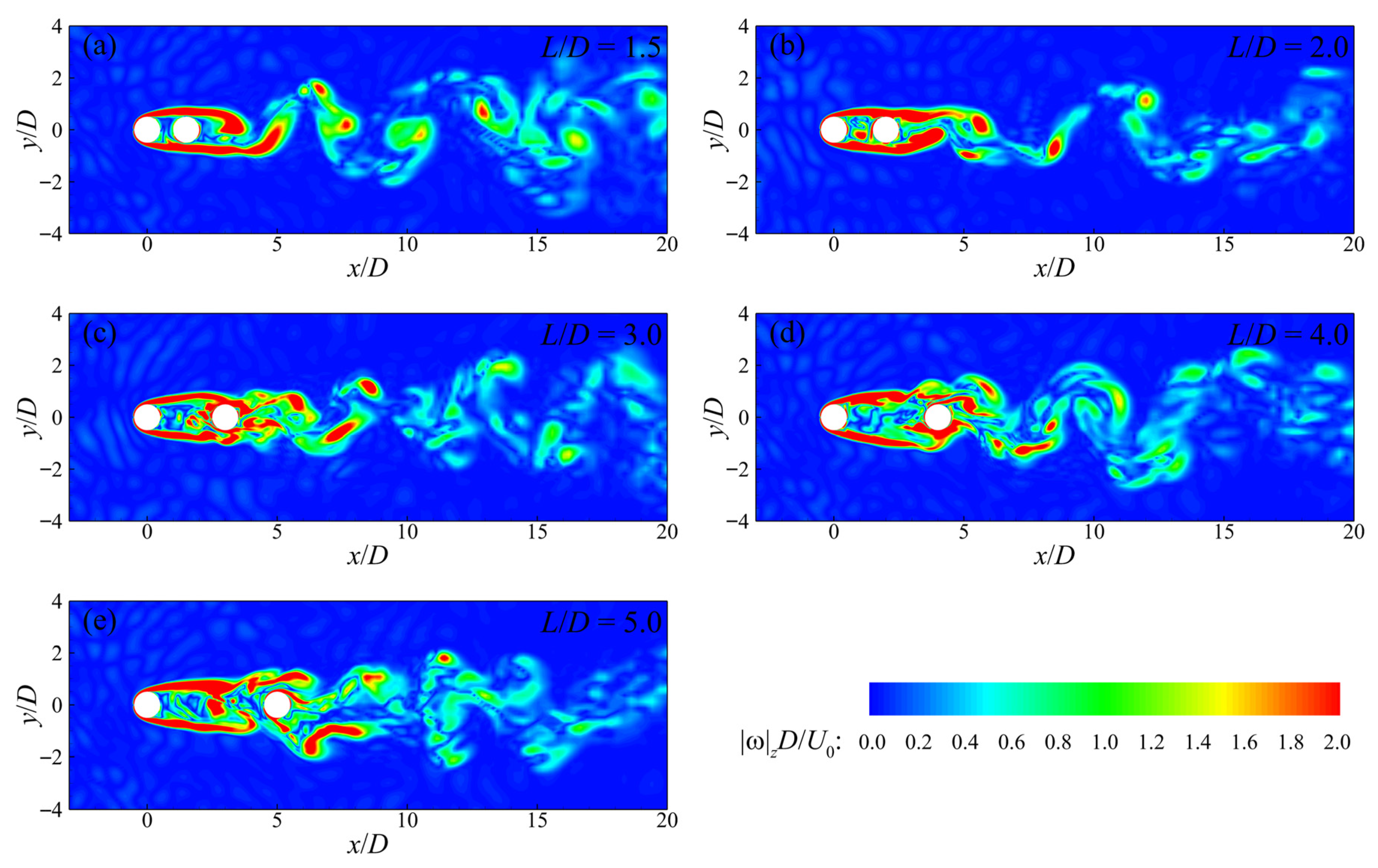
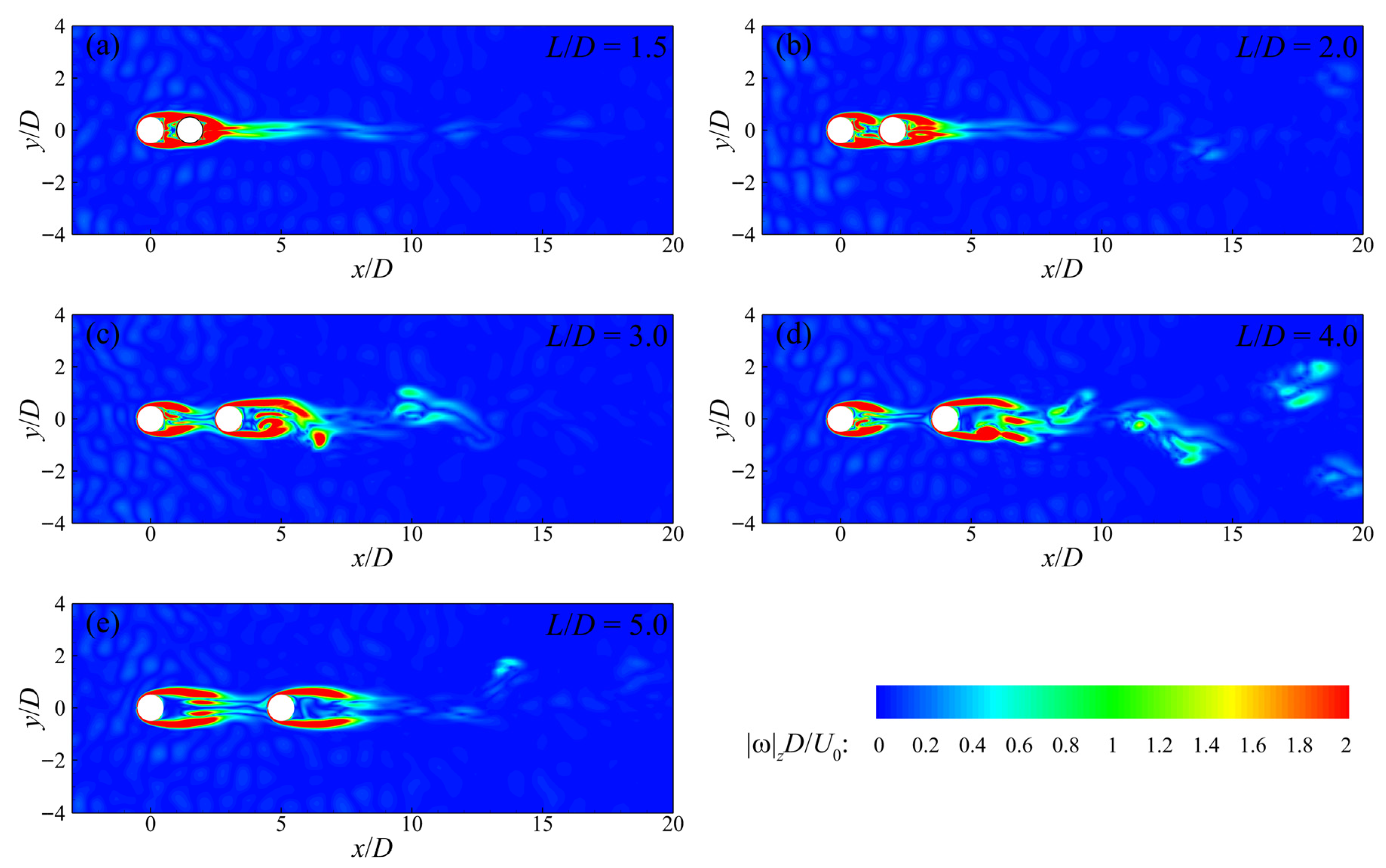
Figure 8 presents instantaneous contours of the magnitude of the vertical vorticity on the horizontal plane at
z = 5
D, which clearly illustrate the transient wake vortex shedding characteristics of C1 and C2. As shown in the figure, within the range of gap ratios considered in the present study, only two wake regimes—namely the extended-body regime and the reattachment regime—are observed on this plane. For
L/
D = 1.5, the laterally separated shear layers form on both shoulders of C1 and extend downstream to a certain distance past C2, where they interact and generate periodically alternating vortex shedding. Under this condition, the tandem-cylinder system behaves similarly to an elliptic cylinder. For
L/
D = 2, the vortex shedding pattern is essentially the same as that for
L/
D = 1.5, and both cases belong to the extended-body regime. However, for
L/
D = 2, the onset location of vortex shedding downstream of C2 is closer to the upstream direction, that is, the distance between the shedding location and the trailing edge of C2 is shorter. This is because the increased gap ratio occupies a larger portion of the development region of the separated shear layers from C1.
For
L/
D = 3–5, the wake pattern corresponds to the reattachment regime. The separated shear layers from C1 reattach onto the surface of C2 before interacting with each other. The reattachment point shifts slightly upstream with increasing
L/D. Periodic vortex shedding then occurs downstream of the cylinder C2. Similarly to the extended-body regime shown in
Figure 8a,b, in the reattachment regime the distance between the vortex shedding location and C2 also decreases with increasing
L/D. However, the wake vortex structures in the reattachment regime are noticeably more complex. It is noteworthy that, although the cases of
L/
D = 4 and 5 fall within the reattachment regime, secondary gap vortices formed by the premature breakdown of the separated shear layers from C1 are observed in the gap region. This phenomenon is an important indicator of the transition from the reattachment regime toward the co-shedding regime [
14]. Moreover, for
L/
D = 5, the strong interaction between these secondary gap vortices and C2. This interaction is manifested as localized regions of high vorticity within the gap region in
Figure 8e. It severely interferes with the wake vortex shedding behind C2, resulting in a wake structure that is less distinct than a classical Kármán vortex street. Similar observations were also reported by Zeng et al. [
13].
In the LES study of infinitely long tandem cylinders conducted by Zeng et al. [
13],
L/
D = 5 was classified within the co-shedding regime,
L/
D = 1.5–4 within the reattachment regime, and only
L/
D = 1.2 within the extended-body regime. The discrepancy between the present results and those of Zeng et al. [
13] is likely attributable to the lower Reynolds number considered in the present study. Zhang et al. [
15] demonstrated that for a fixed gap ratio, increasing the Reynolds number drives the transition of wake regimes. This progression evolves from a no vortex shedding regime, to a single-body regime, and subsequently to a reattachment regime. In the context of the present study and the work of Zeng et al. [
13], the no vortex shedding and single-body regimes corresponds to the extended-body regime. In addition, experimental measurements by Schewe et al. [
2] also indicate that wake regimes are jointly governed by the Reynolds number and the gap ratio.
To explore the influence of the free end of finite-length cylinders on the wake vortex shedding modes of the tandem-cylinder system,
Figure 9 shows instantaneous contours of the magnitude of the vertical vorticity on the horizontal plane at
z = 9.5
D. In contrast to the observations on the
z = 5
D plane,
Figure 9 shows that only for
L/
D = 1.5 does C2 remain enveloped by the separated shear layers of C1, corresponding to the extended-body regime. For
L/
D = 2, the separated shear layers from C1 make only very weak contact with the upstream face of C2, suggesting a transitional state between the reattachment and co-shedding regimes. For
L/
D = 3–5, C2 is completely detached from the separated shear layers of C1, exhibiting characteristics of the co-shedding regime. However, except for the case of
L/
D = 3, no pronounced periodic vortex shedding is observed downstream of the tandem cylinders for the other cases, even though sufficient space is available for shear-layer development in the co-shedding regime. The resulting vertical vorticity distributions bear some resemblance to the no vortex shedding regime reported by Zhang et al. [
15]. This behavior is attributed to the strong downwash near the free end of the cylinders. In the co-shedding regime, separated shear layers form on both sides of the upstream and downstream cylinders and extend downstream. However, their lateral interaction is impeded by the strong downwash induced downstream of the free end. Moreover, the strong downwash accelerates wake velocity recovery, thereby suppressing vortex shedding and leading to an apparent absence of vortex formation. It should be emphasized that the vortex-suppressed behavior observed in the present study differs fundamentally from the no vortex shedding regime reported by Zhang et al. [
15]. In the present case, the absence of a Kármán vortex street arises from the inhibition of shear-layer interaction by the strong downwash near the cylinder free end, whereas in the study of Zhang et al. [
15], its absence results from stable separated shear layers associated with low Reynolds number flows.
Owing to the presence of the free end, a finite-length cylinder induces upward flow upstream and downwash downstream, as clearly illustrated by the time-averaged vertical velocity distribution on the
z = 9.5
D plane shown in
Figure 10. The upstream upward flow results from the vertical deflection of the incoming flow caused by cylinder blockage, whereas the downstream downwash is induced by vertically oriented recirculation vortices. This also implies that weak upward flow may exist locally in regions immediately adjacent to the downstream face of the cylinder in order to satisfy flow continuity. As shown in
Figure 10, the vertical velocity distribution around C1 is similar to that of an isolated cylinder. However, unlike the isolated-cylinder case, except for
L/
D = 5, no upward flow is observed near the trailing edge of C1 for the other cases. This is because the presence of the downstream cylinder restricts the development of the vertical vortices, rendering their characteristic scales too small (<0.5
D) to be intercepted by the
z = 9.5
D plane. Only when the cylinder spacing is sufficiently large (
L/D = 5) do large-scale (>0.5
D) vertical vortices develop, giving rise to observable positive vertical velocities.
The vertical velocity distribution in the vicinity of C2 exhibits distinct patterns with increasing L/D. For L/D = 1.5, the downstream cylinder is completely immersed in the wake of the upstream cylinder and is therefore embedded within a region of negative vertical velocity. For L/D = 2–5, vertical vortices are able to form downstream of C2. Consequently, for L/D = 2, weak upward flow begins to appear near the trailing edge of the downstream cylinder, primarily concentrated in the regions of the laterally separated shear layers. As L/D increases, the region of positive vertical velocity progressively expands upstream and intrudes into the gap region. Despite this expansion, the upward flow remains relatively weak, with magnitudes only about 30–40% of those of the adjacent downwash. In other words, for both C1 and C2, the downstream vertical flow is dominated by downwash. The peak magnitude of downwash within the gap region decreases with increasing L/D, attaining a maximum of approximately −1.1U0 at L/D = 1.5 and decreasing to about −0.7U0 at L/D = 5. The location of the strongest downwash also varies with L/D. For L/D = 1.5 and 2, owing to the limited gap width, the peak downwash occurs in the region immediately adjacent to the upstream face of C2. When the gap becomes moderately larger, the peak downwash shifts toward the vicinity of the trailing edge of C1, although the distance between the peak location and the upstream cylinder increases with increasing L/D. Unlike C1, whose upstream face experiences upward flow due to vertical flow deflection, the upstream face of C2 is always subjected to downwash.
For infinitely long cylinders, although the wake structures also exhibit pronounced three-dimensional features, the intensity of the vertical flow is far weaker than the strong downwash induced by the free end of finite-length cylinders. The strong downwash in the wake of the upstream cylinder introduces substantial streamwise momentum, which significantly accelerates momentum recovery within the gap region. This results in more pronounced lateral flow acceleration regions on both sides of C2 than those reported by Zeng et al. [
13], as shown in
Figure 3.
3.2. Boundary-Layer Separation
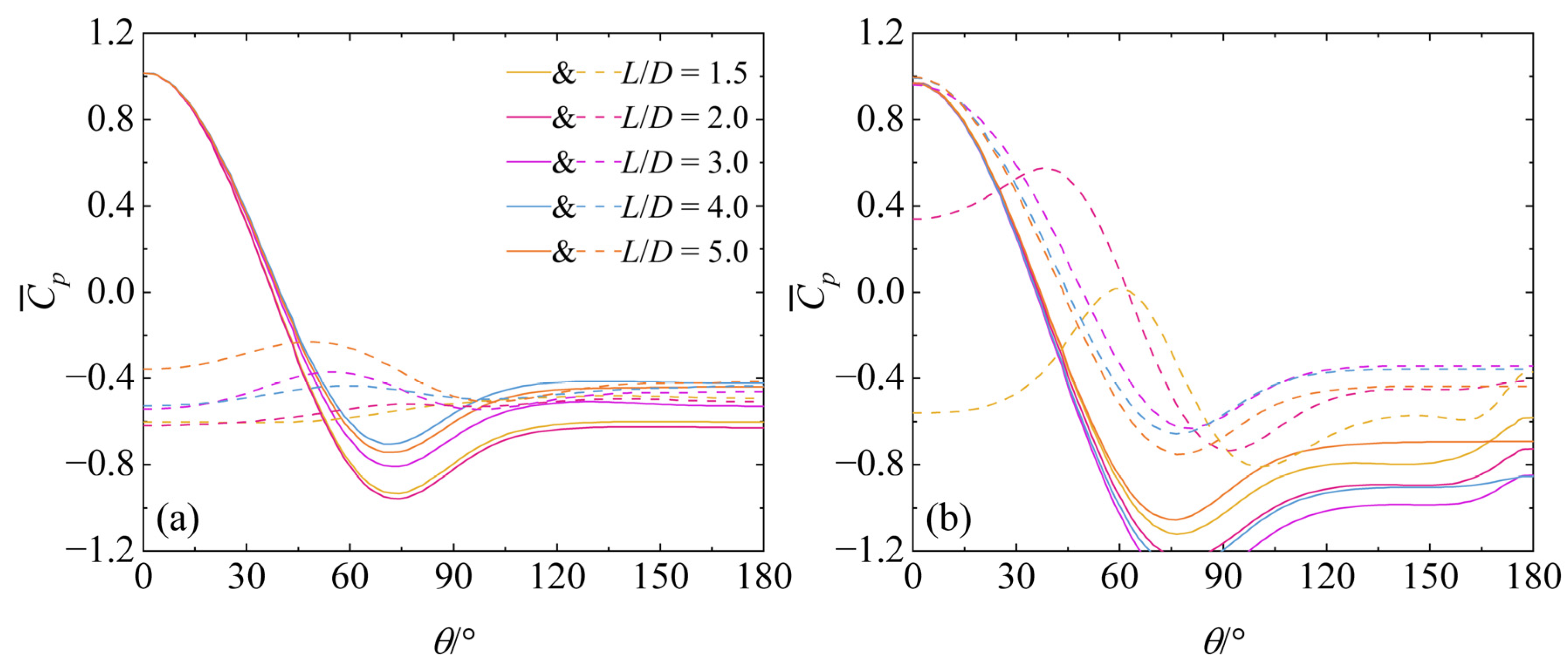
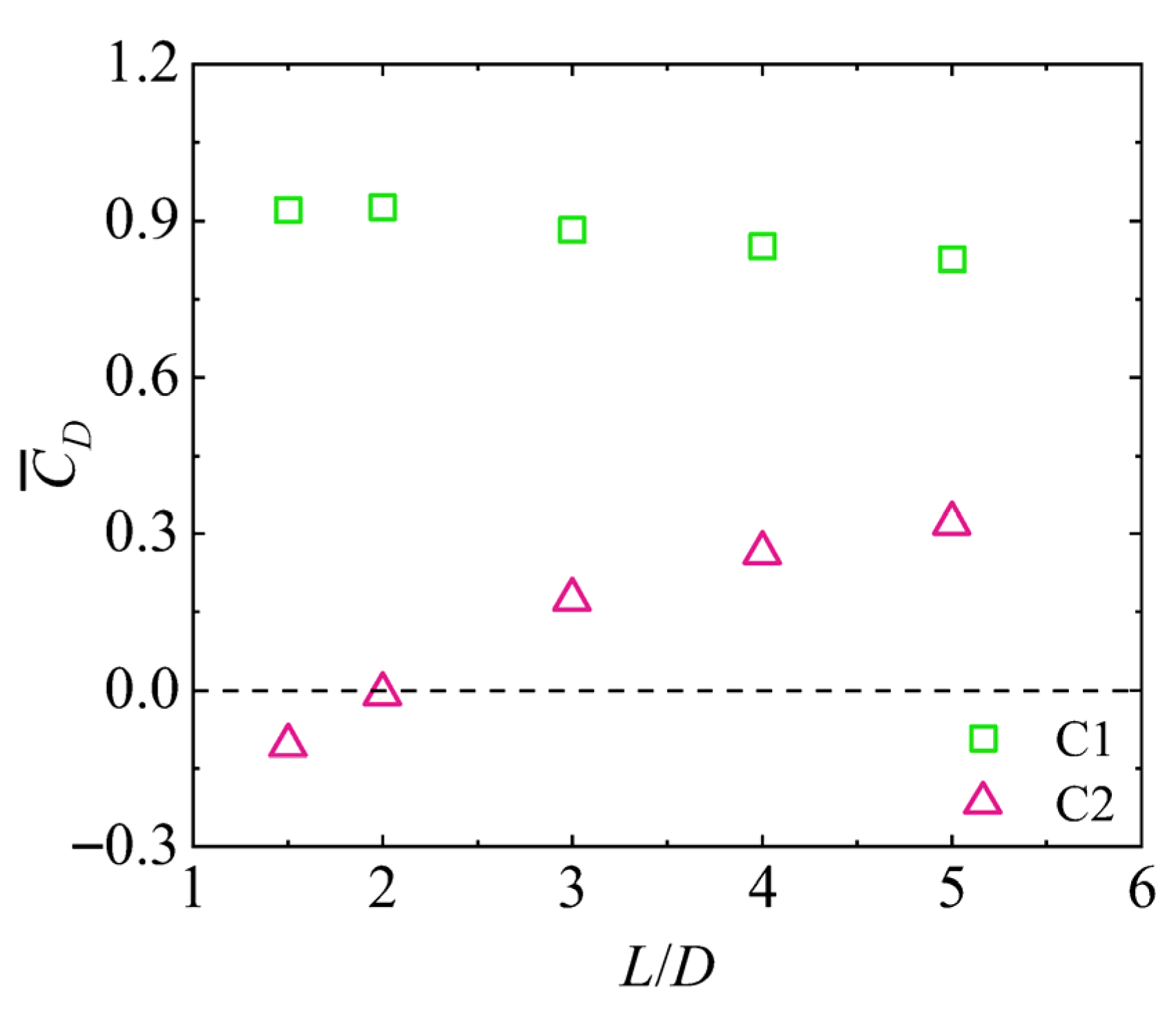
The pressure distribution on the circumferential surface of a cylinder is one of the key parameters governing drag. In this study, the time-averaged pressure coefficient
on the surfaces of tandem cylinders at the
z = 5
D and
z = 9.5
D planes is computed and shown in
Figure 11a and b, respectively. The circumferential coordinate
θ denotes the polar angle measured from the upstream stagnation point of the cylinder (
θ = 0°). At both
z = 5
D and
z = 9.5
D, the shape of the time-averaged pressure coefficient distribution on C1 is essentially identical to that of an isolated cylinder. The only minor difference is that, on the
z = 9.5
D plane for
L/
D = 1.5–4, the pressure coefficient of the downstream cylinder slightly increases toward the trailing edge (
θ ≥150°). This phenomenon was also observed by Etminan et al. [
34] in their study of cylinder arrays and was attributed to the adverse pressure gradient induced by downstream-cylinder blockage. Within the range
θ = 0°−30°, the pressure coefficient curves of the upstream cylinder collapse onto a single curve for all
L/
D cases, consistent with the overlap of the time-averaged streamwise velocity decay curves upstream of the tandem cylinders shown in
Figure 6. Overall, the pressure coefficients in the reattachment regime are higher than those in the extended-body regime; however, within a given wake regime, the influence of
L/
D is not significant, in agreement with Zeng et al. [
13]. The location of the negative pressure peak varies only weakly with wake regime and
L/D.
For the downstream cylinder, at the z = 5D plane the pressure coefficient remains negative over the entire circumference, first increasing to a peak and then decreasing, which is completely different from the isolated-cylinder case. In the extended-body regime (L/D = 1.5 and 2), no pronounced pressure peak is observed. At the z = 9.5D plane, when L/D = 3–5, the pressure coefficient distribution on C2 closely resembles that of an isolated cylinder, although its overall level is higher than that of an isolated cylinder at the same Reynolds number. This further indicates that, at z = 9.5D and L/D = 3–5, the wake regime has transitioned to the co-shedding regime. For L/D = 1.5, the pressure coefficient on C2 remains negative around the entire circumference, as it is completely enveloped by the separated shear layers from the upstream cylinder. When L/D = 2, the pressure distribution on C2 exhibits characteristics of both the reattachment and co-shedding regimes, although the upstream face has already transitioned to positive pressure.
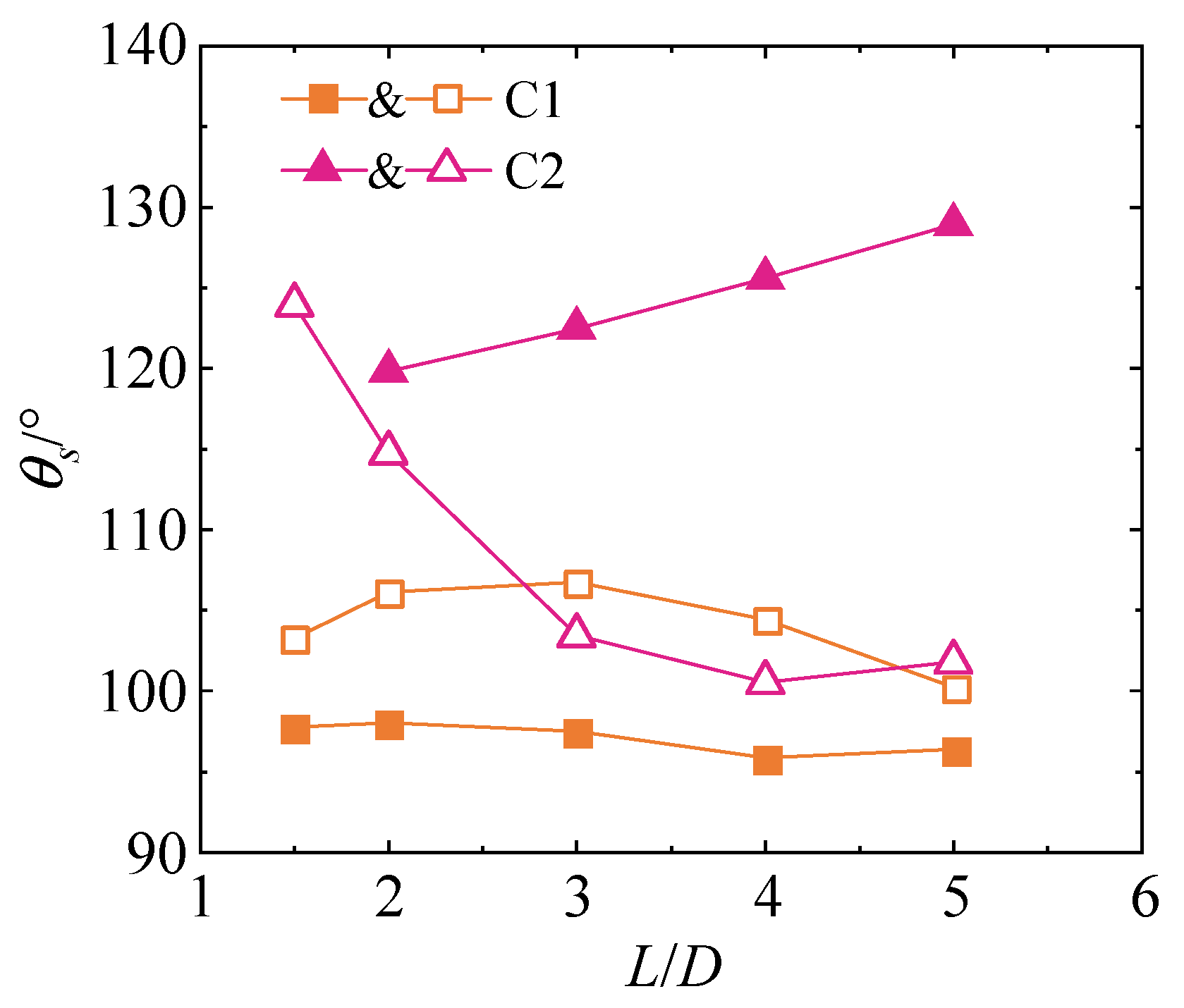
The boundary-layer separation characteristics of the cylinders are quantified by the separation angle
θs, as shown in
Figure 12. In this study, the separation point is defined as the location along the cylinder surface where the wall shear stress changes sign from positive to negative [
34]. For the upstream cylinder, the separation angle on the
z = 5
D plane shows only a slight decreasing trend with increasing
L/D, consistent with Zeng et al. [
13]. On the
z = 9.5
D plane, however, the separation angle first increases and then decreases with increasing
L/D, reaching a maximum at
L/
D = 3. For the downstream cylinder, owing to the distinctly different wake–cylinder interactions at the
z = 5
D and
z = 9.5
D planes, the separation angle exhibits different trends with
L/D. At the
z = 5
D plane, the separation angle of C2 increases monotonically with
L/D, and consequently the recirculation length
Lr decreases with increasing
L/D, as shown in
Figure 7. For
L/
D = 1.5, C2 is completely enveloped by the lateral separated shear layers of C1. Consequently, near-zero streamwise wall shear stress is observed only over the upstream-face region (0°−30°), while the remaining surface is dominated by negative shear stress up to approximately 140°. At the
z = 9.5
D plane, the separation angle of C2 decreases with increasing
L/D. Overall, the separation angle of C2 is larger than that of an isolated cylinder, owing to the turbulence introduced by C1, which delays boundary-layer separation on C2.