Article

Large-Eddy Simulation of Flow Structures Around Two Finite-Length Tandem Cylinders

1
State Key Laboratory of Water Resources Engineering and Management, Wuhan University, Wuhan 430072, China
2
River Research Department, Changjiang River Scientific Research Institute, Wuhan 430010, China
*
Author to whom correspondence should be addressed.
Water 2026, 18(3), 305; https://doi.org/10.3390/w18030305
Submission received: 21 December 2025 / Revised: 19 January 2026 / Accepted: 23 January 2026 / Published: 25 January 2026
(This article belongs to the Special Issue Effects of Vegetation on Open Channel Flow and Sediment Transport)

Abstract

Large-eddy simulation (LES) is utilized to elucidate the flow characteristics and overall time-averaged drag coefficients of finite-length tandem cylinders. This study focuses explicitly on the three-dimensional effects induced by the free end, a feature absent in classical studies of infinite (two-dimensional) tandem cylinders. By varying the cylinder spacing ratio L/D from 1.5 to 5, the evolution of wake regimes and their variations along the vertical direction of the cylinders are systematically examined. The results reveal a distinct vertical transition of wake patterns: at the mid-height plane, the wake falls into the extended-body regime for L/D = 1.5 and 2, where vortex shedding occurs downstream of the downstream cylinder. When L/D = 3–5, the flow enters the reattachment regime, characterized by the separated shear layers from the upstream cylinder reattaching onto the windward face of the downstream cylinder, while a Kármán vortex street persists in its wake. In contrast, at planes near the free end, the flow characteristics shift towards the co-shedding regime for L/D ≥ 2, though strong downwash suppresses organized vortex shedding. This vertical transition of wake regimes, driven by free-end downwash, clarifies a significant gap in applying two-dimensional regime classifications to finite-length bodies. The overall time-averaged drag coefficients of the upstream and downstream cylinders show opposite trends with increasing L/D: the former decreases, whereas the latter increases. The force on the downstream cylinder changes from an upstream-directed drag to a downstream-directed thrust at L/D = 2. Overall, the results indicate that for L/D = 3–5, the overall drag coefficient of the cylinder is dominated by the co-shedding regime. These findings advance the understanding of flow interference in finite-length tandem configurations and offer refined insights for modeling analogous systems such as adjacent vegetation stems in aquatic environments.

1. Introduction

The study of flow structures around multiple cylinders is a classical problem in fluid dynamics. Owing to its broad range of potential engineering applications—such as marine risers, local ship structures, wind fields around buildings, and interactions among stems of aquatic vegetation—this topic holds considerable practical importance. Understanding the associated hydrodynamic mechanisms, including flow velocity redistribution, boundary-layer separation, flow-induced drag, and vortex-induced vibrations, is essential for optimizing structural configurations and improving energy utilization efficiency. Consequently, this topic has attracted extensive attention from the fluid dynamics research community [1,2,3,4,5,6].
As one of the most fundamental units of multiple-cylinder configurations, tandem circular cylinders have been extensively investigated over the past several decades. These studies, employing both experimental measurements and computational fluid dynamics simulations, have particularly focused on systems of infinitely long tandem cylinders with equal diameters [1,7,8]. For example, Hu et al. [7] employed three-dimensional numerical simulations to investigate the flow structures around tandem cylinders under subcritical and supercritical conditions, analyzing the influence of spacing ratio on wake interference. Skonecki and Buick [8] studied the drag coefficients and wake regimes of twin cylinders arranged in tandem, side-by-side, and staggered configurations, and discussed their dependence on the Reynolds number. For tandem-cylinder systems, the wake patterns are commonly classified based on the dynamical interactions between the recirculation region and separated shear layers of the upstream and downstream cylinder. Three primary regimes have been identified: the extended-body regime, the reattachment regime, and the co-shedding regime, [9,10,11,12]. Zeng et al. [13] investigated the flow structures around tandem circular cylinders using LES. The study was conducted at a cylinder Reynolds number of ReD = 3900, with the gap ratio L/D (where L denotes the center-to-center spacing between the cylinders and D is the cylinder diameter) varying from 1.2 to 7. Their results reconfirmed the existence of the extended-body regime (L/D = 1.2), the reattachment regime (L/D = 1.5–4), and the co-shedding regime (L/D = 5–7). In addition, they identified a transitional regime between the reattachment and co-shedding regimes [14]. Zhang et al. [15] combined particle image velocimetry and large-eddy simulation to examine the effects of Reynolds number and gap ratio on wake vortex shedding modes and boundary-layer separation characteristics of infinitely long tandem cylinders. Unlike the study of Zeng et al. [13], they focused on low Reynolds number flows. Consequently, in addition to the four wake regimes mentioned above, a no vortex shedding regime was observed under conditions of simultaneously low Reynolds number and small cylinder spacing. This regime is characterized by stable separated shear layers forming on both sides of the upstream cylinder, which extend downstream to fully envelop the downstream cylinder, without the formation of a Kármán vortex street in the wake of the tandem-cylinder system.
Compared with infinitely long cylinders, the wakes of finite-length cylinders exhibit much more pronounced three-dimensional characteristics. As the upstream flow approaches a finite-length cylinder, it is deflected not only laterally toward both sides but also upward toward the free end of the cylinder [16,17,18,19]. Near the free end of the cylinder, the fluid wrapping around the top forms a strong downwash, which generates vertical recirculation vortices. This downwash interferes with the interaction of the separating shear layers from the lateral two sides of the cylinder and can suppress the formation of the Kármán vortex street in horizontal planes when the aspect ratio is small (especially below 2) [19]. Simultaneously, the high streamwise momentum carried by the downwash from above the cylinder accelerates the recovery of the wake velocity, thereby increasing the pressure in the wake region and reducing the cylinder drag force [20]. Consequently, the flow past finite-length tandem circular cylinders is considerably more complex than that around infinitely long cylinders, exhibiting stronger three-dimensional features. Early studies on finite-length tandem cylinder systems primarily focused on drag characteristics. Luo et al. [21] experimentally measured the drag forces and surface pressure distributions of finite-length tandem cylinders and analyzed the variation in the time-averaged drag coefficient along the cylinder height. They found that the amplitude of the drag-coefficient variation along the height strongly depends on the prevailing wake regime and is directly influenced by wake pressure variations, with higher local drag near the free end. Sumner and Reitenbach [11] measured the overall time-averaged drag coefficients and vortex shedding frequencies of finite-length tandem cylinders and examined their dependence on the gap ratio and the cylinder aspect ratio. However, their results were based on the overall cylinder behavior and did not examine the variation along the cylinder height. Schewe et al. [2] reported that the overall time-averaged drag coefficients of the upstream and downstream cylinders exhibit opposite trends with increasing Reynolds number, decreasing for the former while increasing for the latter. Over the past decade, with advances in flow-field measurement techniques and computational fluid dynamics, analyses of three-dimensional flow structures have been increasingly conducted [22,23]. Palau-Salvador et al. [24] simulated the flow past tandem cylinders with shallow submergence. Although no vortex shedding was observed in the instantaneous flow field within the gap region, a recirculation vortex occupying the entire gap region appeared in the time-averaged flow field, and pronounced downwash was also identified in the gap. However, their analysis of the in-plane flow patterns was limited to a horizontal plane at mid-height of the cylinders. Kim and Christensen [23] focused exclusively on flow structures in vertical planes, providing a detailed analysis of upward and downward motions, as well as the recirculation bubble and velocity distributions. The strong downwash induced by the free end of finite-length cylinders is expected to play a critical role in determining the wake regimes of finite-length tandem cylinder systems, thereby affecting boundary-layer separation characteristics and hydrodynamic drag. In particular, near the free-end region, for a fixed gap ratio and Reynolds number, the wake regime may vary along the vertical direction due to the influence of downwash. Nevertheless, a clear understanding of how the free-end downwash fundamentally alters wake interactions in a tandem configuration remains lacking. While previous studies on finite-length tandem cylinders have provided valuable insights into overall drag and Strouhal number, their flow analyses have often been confined to specific horizontal or vertical planes. This approach may overlook potential variations in wake regimes along the cylinder height induced by the downwash. In contrast, the well-established regime classifications for infinite (two-dimensional) tandem cylinders do not account for this three-dimensional, free-end-induced effect.
To address this gap, the present study employs high-resolution LES to systematically investigate the flow around two finite-length cylinders in a tandem arrangement. Leveraging the advantage of numerical simulations in obtaining full-field data [25,26], this study aims to analyze the instantaneous and time-averaged flow structures, vortex dynamics, boundary layer characteristics, and overall drag. The primary focus is on elucidating the vertical variation in wake regimes—the extended-body, reattachment, and co-shedding regimes—and their dependence on the spacing ratio. This work explicitly examines the three-dimensional flow structures at different horizontal planes, contrasting the wake dynamics near the mid-height with those close to the free end. In doing so, it provides a mechanistic explanation for the integrated force coefficients that goes beyond correlations based solely on spacing. The influence of bed friction is excluded, as the focus is placed on the flow dynamics in the upper region of the cylinders where the free-end effect is dominant.

2. Methods

2.1. Governing Equations

Experimental observations in vegetated flows indicate that the wake becomes fully turbulent for stem Reynolds numbers ReD > 120 (ReD = UD/ν, U is the reference velocity, D is the stem diameter, and ν is the kinematic viscosity of water) [15,27,28,29]. At the present ReD = 540, the flow is expected to exhibit developed three-dimensional turbulent structures. To accurately resolve the transient vortex dynamics, particularly the free-end downwash and the consequent wake regimes, LES is employed to solve the three-dimensional instantaneous flow field. LES provides an optimal balance between solution fidelity and computational cost for this problem, as it explicitly resolves the large energy-carrying eddies dominating the wake interference, while modeling the smaller subgrid-scale motions. A spatial filtering operation applied to the governing equations are given by
u i x i = 0 ,
u i t + u i u j x j = 1 ρ p x i + ν 2 u j x j x j τ i j x j ,
where the angle brackets “〈 〉” denote the spatial filtering operation; t is time; p is pressure; ui (u, v, w) represents the instantaneous velocity components along the Cartesian coordinates xi (x, y, z); τij is the subgrid-scale stress tensor. In this study, the wall-adapting local eddy-viscosity (WALE) model developed by Nicoud and Ducros [30] is adopted to model the subgrid-scale stresses. This model provides correct wall-asymptotic behavior for wall-bounded flows. This model is adopted because it provides correct wall-asymptotic behavior for wall-bounded flows and automatically returns zero eddy viscosity in laminar shear flows, enabling a more accurate treatment of near-wall regions and laminar-turbulent transition. The WALE model has demonstrated high precision in previous simulations of bluff body flows [31,32,33].

2.2. Model Setup

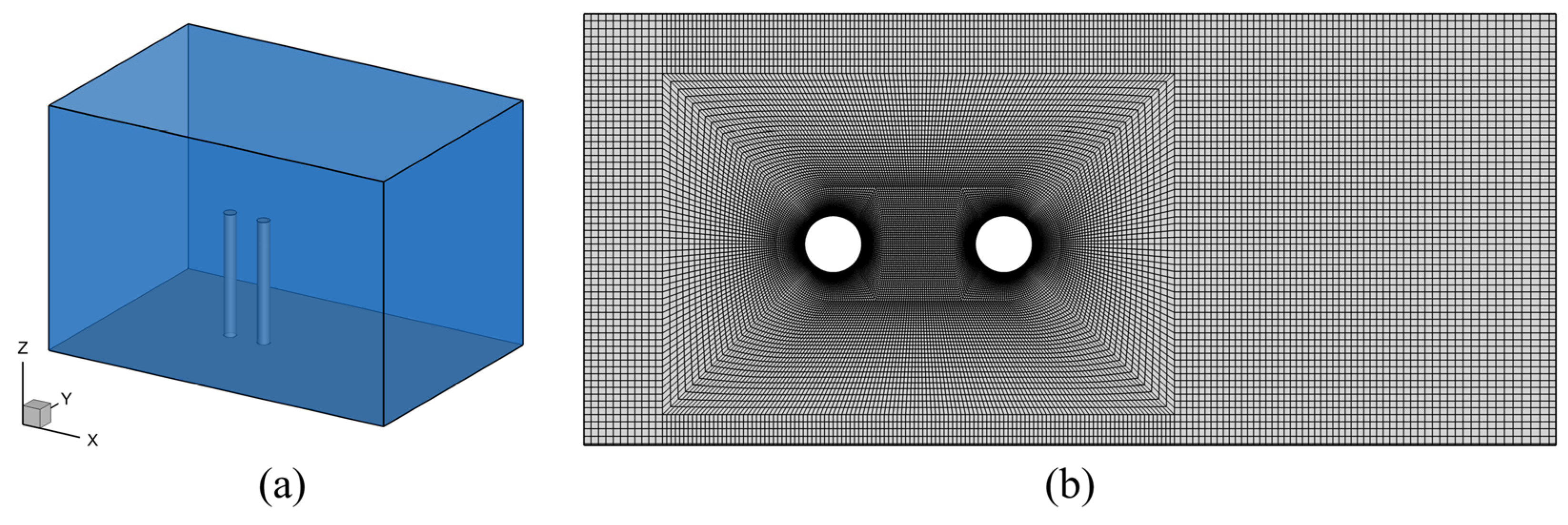
The physical background of this study corresponds to aquatic plants in freshwater wetlands, where plant stems typically exhibit large aspect ratios (the ratio of plant height to stem diameter), usually exceeding 10 [34,35]. To investigate the flow structures and interactions between adjacent upstream and downstream stems, the system is idealized as a tandem configuration composed of two slender circular cylinders. Three-dimensional instantaneous turbulent flow is simulated using the LES approach to analyze complex flow structures and drag characteristics, as illustrated in Figure 1a. The influence of bottom bed friction on the flow dynamics is neglected; that is, the present study focuses on the hydrodynamic processes occurring in regions of finite-length cylinders with large aspect ratios that are sufficiently far from bed effects. The computational domain has a total length of 30D, a width of 20D, and a height of 20D, and contains an upstream cylinder (C1) and a downstream cylinder (C2). The separation between the upstream cylinder’s center and the inlet and to the two lateral boundaries is 10D, which is sufficiently large to minimize boundary effects on the cylinder wakes and is a domain size commonly adopted in studies of flow past cylinders [36,37,38]. In the vertical direction, the cylinder height is h = 10D, which is sufficient to accommodate the downwash induced by the free end of the cylinder. The cylinder diameter is D = 3.6 mm, and the free-stream velocity is U0 = 0.15 m/s, corresponding to a cylinder Reynolds number of ReD = U0D/ν = 540, which lies within the Reynolds number range characteristic of natural wetland waters [39,40]. In the simulations, five different center-to-center spacings L between the cylinders are considered, corresponding to five gap ratios L/D:L/D = 1.5, 2, 3, 4, and 5. The upstream inflow velocity, as well as the cylinder height and diameter, are kept constant; thus, only the effects of the gap ratio on the flow structures and drag characteristics are examined. The center of the upstream cylinder’s bottom face serves as the origin of the Cartesian coordinate system. The x-, y-, and z-axes point in the downstream, lateral, and free-surface directions, respectively.

2.3. Numerical Methods

The simulation domain is partitioned into several mesh blocks, and an O-type grid topology is adopted around the cylinders, resulting in a fully hexahedral structured mesh throughout the domain. In the horizontal planes, the mesh is refined in the vicinity of the cylinders and within the near-wake region. The grid size in these refined zones is approximately 0.03D. This level of refinement ensures that the separated shear layers on both lateral sides of the cylinders, as well as their complex interactions, can be directly resolved. In the far-wake region and in areas laterally distant from the cylinders, the grid size increases progressively, reaching a maximum of approximately 0.2D. Along the circumference of each cylinder, 180 grid points are distributed, which is sufficient to accurately compute the hydrodynamic forces and to resolve the flow separation locations. In the vertical direction, the mesh is substantially refined near the free end of the cylinders to accurately resolve the vertical shear layers, as well as the upward flow upstream and the strong downwash downstream of the cylinders. The grid size is gradually increased toward both the bottom and top boundaries of the computational domain, with a maximum value of approximately 0.2D. The height of the first grid cell off the cylinder surface is 0.0045D, corresponding to a maximum nondimensional wall distance of y+ ≈ 0.8. This mesh configuration follows that adopted in the LES studies of Zeng et al. [14,41], in which the Reynolds number ReD = 3900 is higher than that considered in this work (ReD = 540). A grid independence study was conducted for the case of L/D = 1.5. Using the baseline mesh configuration, the overall time-averaged drag coefficients for C1 and C2 were found to be 0.92 and −0.105, respectively. The dimensionless vortex shedding frequency (Strouhal number) derived from the lift coefficient time histories for both cylinders was 0.1488. When the number of grid cells was increased by a factor of 1.4 in all three directions compared to the baseline mesh, the corresponding overall time-averaged drag coefficients for C1 and C2 were 0.918 and −0.106, and the Strouhal number was 0.1499. These negligible differences indicate that, with the present grid resolution, grid-independent solutions are achieved. Depending on the gap ratio, the grid count within the domain varies between 6.0 and 7.83 million. The mesh of the computational domain on the horizontal plane at z = 5D for the case of L/D = 3 is shown in Figure 1b.
The inflow boundary is prescribed with a uniform velocity U0. Instantaneous velocity fluctuations are generated using the spectral synthesizer method, with a turbulence intensity of 5% and a turbulence length scale of 3.6 mm (corresponding to the cylinder diameter). These values are representative of typical vegetated flows. The same inflow conditions are applied to all simulation cases. A pressure-outlet condition is applied to the outlet boundary. In the lateral direction, symmetry boundary conditions are applied at the two side boundaries of the computational domain. The distance from these side boundaries to the cylinder is 10D, which, according to previous studies [13,27], is sufficient to ensure that side boundary effects are negligible. In the vertical direction, symmetry boundary conditions are also applied at both the bottom boundary and the top free surface. Since the distance from the free surface to the free end of the cylinder is 10D, the corresponding cross-sectional blockage ratio is 0.025. Consequently, the water surface fluctuations induced by cylinder blockage are expected to be minimal, and treating the free surface as a rigid lid is a reasonable assumption. Treating the free surface as a rigid lid may, to some extent, enhance the downwash downstream of the cylinder’s free end. This, in turn, could accelerate wake recovery and reduce the drag force. However, under the present low blockage ratio, this effect is anticipated to be very weak. The purpose of treating the bottom as a symmetry boundary is to exclude the influence of bed friction, meaning this study focuses on the flow around the upper part of the slender finite cylinder, away from the bed-friction-dominated region. Nonetheless, it should be acknowledged that applying symmetry conditions at the lateral, bottom, and top boundaries constitutes an idealized configuration of the actual physical problem. The cylinder surfaces are modeled as smooth, no-slip wall boundaries, and the viscous sublayer is captured without resorting to wall models.
The numerical solution is obtained with a finite-volume LES code. The SIMPLEC algorithm resolves pressure-velocity coupling; second-order central differencing discretizes the spatial terms, and a fully implicit second-order scheme handles time integration. The numerical framework adopted in the present investigation has undergone thorough validation in prior research. It has been applied to flows past a single infinitely long cylinder, a finite-length cylinder, and multiple cylinders. These validations cover Reynolds numbers in the range ReD = 300–600. The computed drag coefficients, pressure coefficients, and vortex shedding frequencies closely match the available experimental data and DNS results [16,27,33]. This provides confidence in the accuracy of the present simulations for the flow past finite-length tandem cylinders at ReD = 540. Further details regarding the validation cases is available in Liu et al. [16,27,33]. In the present simulations, the time step is set to 0.002 s, and the data sampling frequency is fixed at 250 Hz to balance computational cost and temporal resolution. Each simulation is first run for a duration of 650D/U0 to eliminate initial transients, followed by an additional 3750D/U0 over which statistical quantities are collected.

3. Results and Discussion

3.1. Time-Averaged and Transient Flow Structures

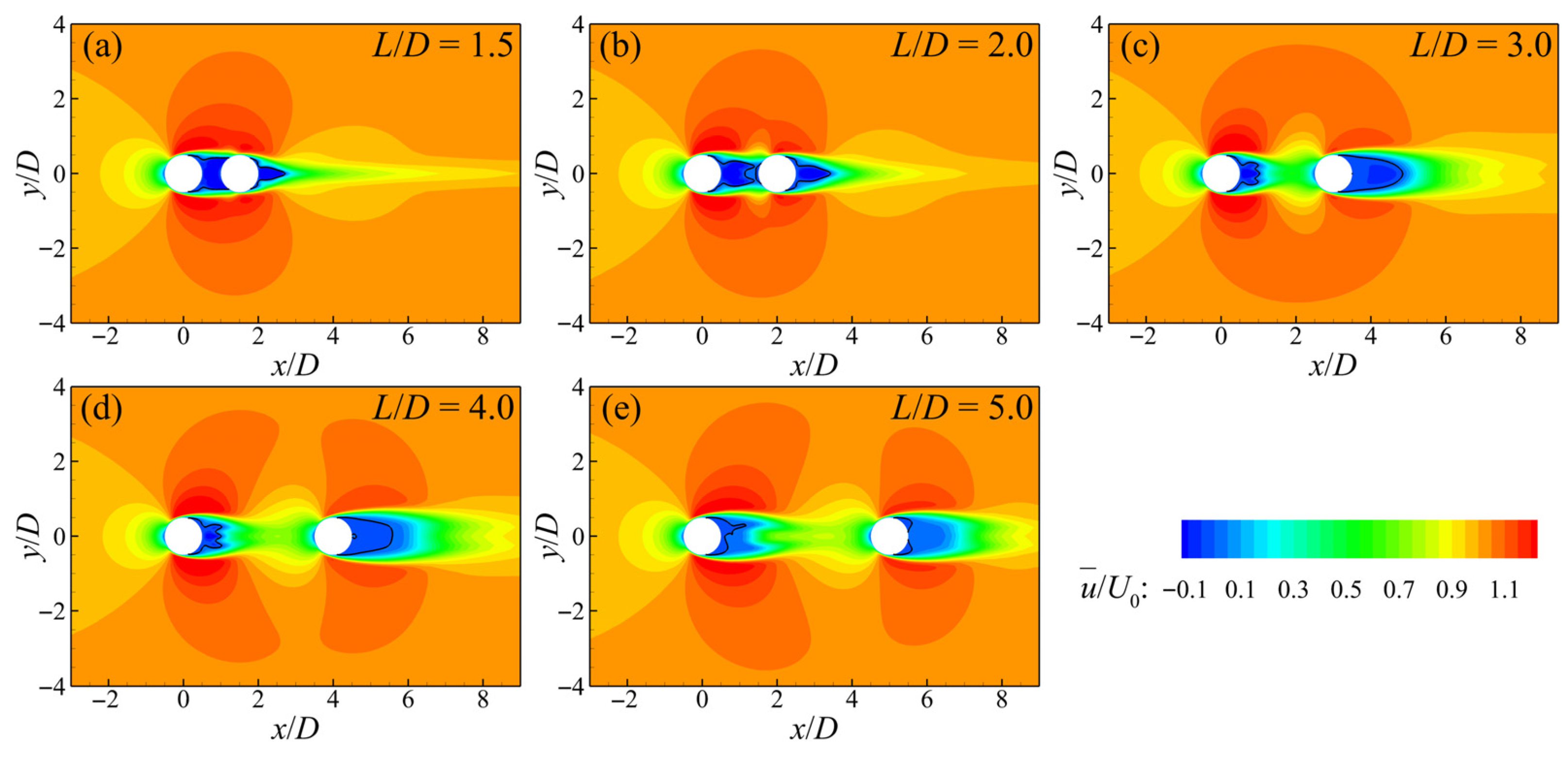
Figure 2 depicts the time-averaged streamwise velocity on the horizontal plane at half of the cylinder height, normalized by the free-stream velocity U0, with the zero-velocity contour indicated by a black line to identify the recirculation regions. Overall, C1 and C2 consistently behave as an integrated body. The resulting velocity distribution resembles that observed in the flow past a single circular cylinder, with local acceleration regions forming on both lateral sides of the cylinders. The tandem-cylinder system thus tends to exhibit an elliptic-cylinder-like behavior with its major axis aligned with the streamwise direction. Accordingly, none of the cases considered belongs to the co-shedding regime. From a local perspective, distinct differences are observed between the cases of L/D = 1.5 and 2 and those of L/D = 3–5. In terms of the magnitude of lateral flow acceleration, the former two cases exhibit stronger blockage effects than the latter three, suggesting that they may fall into different flow regimes. For all five cases, recirculation occurs downstream of both C1 and C2. In the cases of L/D = 1.5 and 2, the width of the recirculation region between C1 and C2 remains nearly constant along the streamwise direction and is comparable to the cylinder diameter. This indicates that C2 is completely enveloped within the recirculation region of C1. This behavior is a typical feature of the extended-body regime. In contrast, for L/D = 3–5, the recirculation region fills the entire streamwise gap between C1 and C2 due to the blockage imposed by C2. Its width, however, decreases along the streamwise direction and then increases again as it approaches the downstream cylinder, as shown in Figure 2c–e. This behavior indicates that these cases correspond to the reattachment regime, a conclusion that will be repeatedly confirmed in the subsequent analysis. The wake behind C2 is wider for L/D = 1.5 and 2 than for L/D = 3–5, aligning with the observations of Zeng et al. [13] and Zhang et al. [15].
The free end of a finite-length cylinder induces a downwash immediately downstream of the trailing edge, which interferes with the interaction of the separated shear layers on the lateral sides of the cylinder and alters the circumferential pressure distribution. This mechanism has been well documented for flow past a single finite-length cylinder [18,19,42]. To illustrate the influence of the cylinder free end on the time-averaged velocity distribution of the tandem-cylinder system, Figure 3 shows the normalized time-averaged streamwise velocity on a horizontal plane located 0.5D below the cylinder top (z = 9.5D). It can be seen that, with increasing L/D, the velocity distributions exhibit patterns that are markedly different from those on the z = 5D plane shown in Figure 2. Only for L/D = 1.5 does the downstream cylinder remain completely immersed in the recirculation region of C1. For the other cases, the downstream cylinder is detached from the upstream recirculation region, and its upstream face is exposed to positive streamwise velocity. Both the upstream and downstream cylinders exhibit flow acceleration on their lateral sides, resembling the behavior of two isolated cylinders. This suggests that, on the z = 9.5D plane, the cases of L/D = 2–5 may fall into the co-shedding regime. The acceleration region around the downstream cylinder is, however, significantly smaller than that around C1. This indicates that the flow acceleration induced by the downstream cylinder is weakened by the shielding effect of C1. As the gap ratio increases, the influence of C1 on C2 gradually diminishes. For L/D = 2–5, recirculation regions form independently downstream of C1 and C2, with the recirculation length of C2 being, overall, slightly larger than that of C1. This behavior differs from observations for infinitely long tandem cylinders reported by Zeng et al. [13], in which the recirculation region downstream of the cylinder C2 is always significantly smaller than that of the upstream cylinder. It is worth noting that, although the case of L/D = 1.5 remains in the extended-body regime on the z = 9.5D plane, the downstream cylinder already begins to exhibit a tendency to transition toward the reattachment regime.
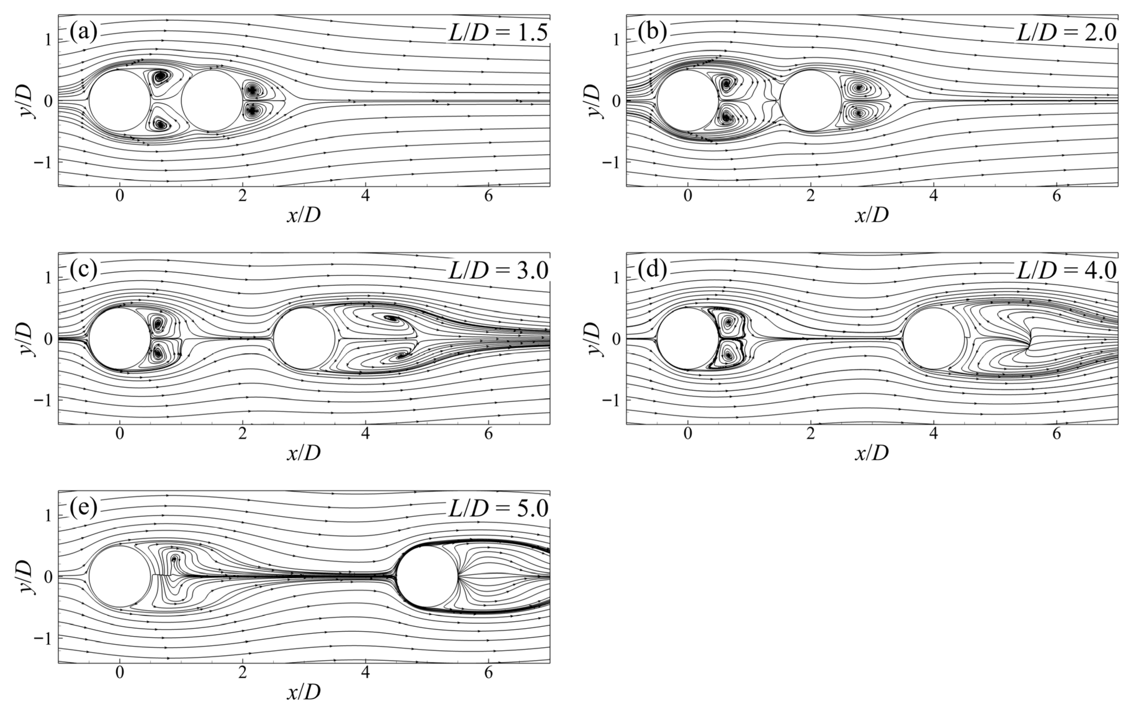
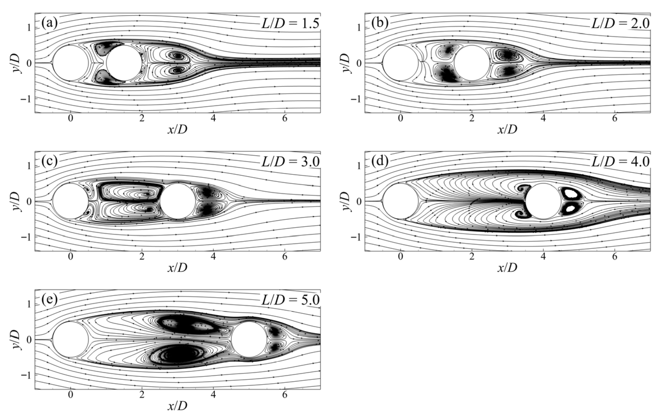
The two-dimensional time-averaged streamlines on the horizontal plane at half of the cylinder height are depicted in Figure 4. For all cases, recirculation vortices form both in the gap region between the cylinders and downstream of the cylinder C2, and they are firmly attached to the surface of the downstream cylinder. For L/D = 1.5 and 2, the recirculation vortex occupies most of the gap region near the downstream side. It is stretched and twisted downstream along the surface of C2, while the vortex core remains approximately centered in the streamwise direction. When the system is in the reattachment regime, i.e., for L/D = 3–5, the recirculation vortex fills the entire gap region, and its core is markedly shifted toward the downstream cylinder. The overall size of the gap-region recirculation vortex increases with increasing L/D. In contrast, the size of the recirculation vortex downstream of the downstream cylinder generally decreases as the gap ratio increases. These trends are consistent with the time-averaged velocity distributions shown in Figure 2. For L/D = 1.5, because C2 is fully surrounded by the laterally separated shear layers of C1, its wake vortex is significantly larger than that of an isolated cylinder of the same diameter. In the cases of L/D = 1.5 and 3, secondary recirculation vortices are also observed on the cylinder surfaces, similar to those reported for flow past an isolated cylinder. Their locations, however, differ: for L/D = 1.5, they appear near the trailing edge of C2, whereas for L/D = 3, they occur near the trailing edge of C1.
Figure 5 illustrates the time-averaged recirculation patterns on the horizontal plane close to the cylinder free end (z = 9.5D). Unlike the gap-region recirculation vortices attached to C2 observed in Figure 4, the gap-region recirculation vortices on the z = 9.5D plane are anchored to the trailing edge of the upstream cylinder. Only for L/D = 1.5, owing to the limited gap length, does the recirculation vortex still occupy the entire gap region. For L/D = 2–4, recirculation vortices form separately downstream of C1 and C2, behaving similarly to those behind isolated cylinders. This observation agrees with the recirculation patterns by Zeng et al. [14] in the co-shedding regime. The sizes of the recirculation vortices downstream of C1 for L/D = 3 and 4 are comparable and slightly smaller than that for L/D = 2. For L/D = 5, the presence of vertical vortical structures interferes with the formation of horizontal-plane recirculation vortices, resulting in pronounced distortion of the two-dimensional streamlines. The differences in the time-averaged recirculation patterns between Figure 4 and Figure 5 further demonstrate that the wake-regime classification of the tandem-cylinder system varies along the vertical direction.
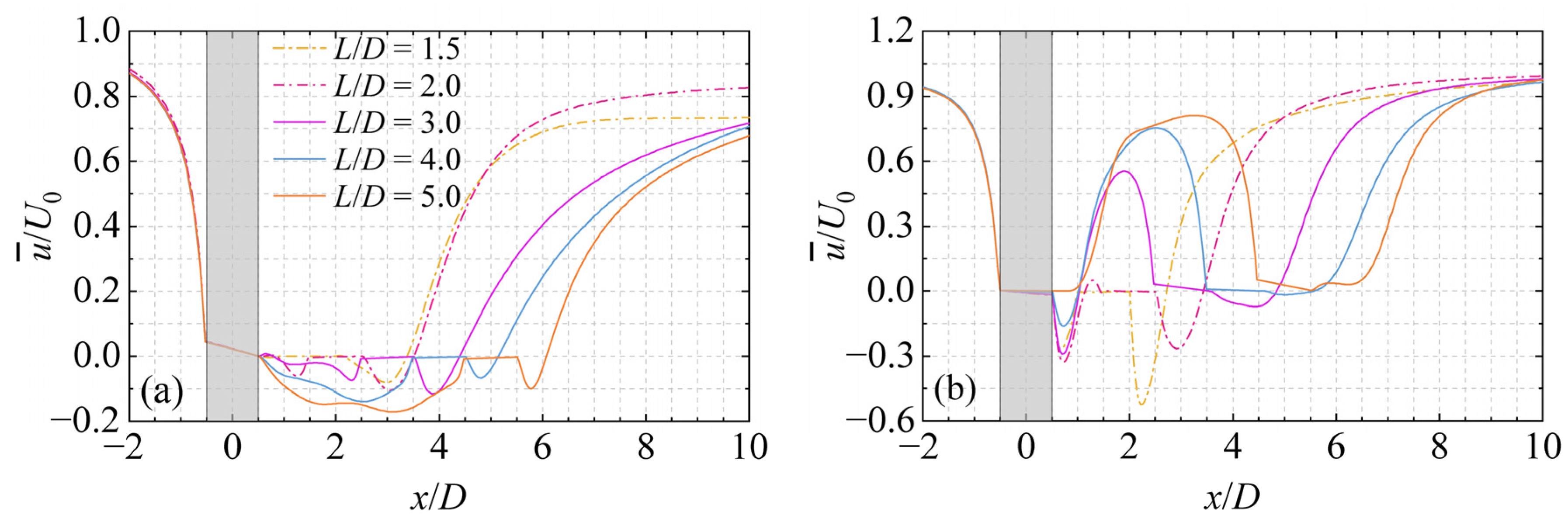
To further quantify the wake velocity recovery and the effects of the gap ratio, Figure 6 presents the centerline distributions of the time-averaged streamwise velocity on the horizontal planes at z = 5D and z = 9.5D. In the upstream region of the tandem-cylinder system, compared with the z = 5D plane, the onset of streamwise velocity decay on the z = 9.5D plane occurs farther downstream, but the decay rate is higher. On both horizontal planes considered, the streamwise velocity decay in the upstream region is independent of the gap ratio. In other words, the pressure distribution on the upstream face of C1 is not affected by the gap ratio. On the z = 5D plane, within the gap region, except for the case of L/D = 1.5, in which the flow remains nearly stagnant throughout the gap, all other cases exhibit pronounced reverse flow. The intensity of the reverse flow increases with increasing L/D, with the maximum reverse velocity being −0.06U0 at L/D = 2 and reaching −0.17U0 at L/D = 5. Nevertheless, because the case of L/D = 2 still belongs to the extended-body regime, the region within approximately 0.5D downstream of the trailing edge of the upstream cylinder remains nearly stagnant. The strongest reverse flow consistently occurs in the portion of the gap region close to the downstream cylinder. This observation aligns with the downstream-shifted vortex cores of the gap-region recirculation vortices observed in the time-averaged streamlines shown in Figure 4. On the z = 9.5D plane, the situation is markedly different. Within the gap region, only the case of L/D = 5 does not exhibit negative velocities over the entire gap, while maintaining a nearly stagnant flow over a streamwise extent of about 0.5D immediately downstream of the upstream cylinder. For the other cases, the streamwise extent of the reverse-flow region downstream of C1 is nearly identical, approximately 0.5D. Downstream of the reverse-flow region within the gap, the streamwise velocity rapidly recovers and then decreases again as it approaches the downstream cylinder, owing to the blockage imposed by C2. The maximum positive streamwise velocity within the gap increases with increasing L/D, because larger gap ratios provide a longer distance for streamwise velocity recovery. The presence of positive streamwise velocity within the gap is one of the characteristic features distinguishing the co-shedding regime from the reattachment regime. In the wake of C2, the maximum reverse velocity decreases with increasing L/D. At L/D = 4, the reverse velocity approaches zero, and at L/D = 5, the reverse flow disappears completely, which agrees with the absence of a recirculation vortex in Figure 5e. Because the case of L/D = 1.5 remains in the extended-body regime, appreciable reverse flow persists throughout the gap region and downstream of C2.
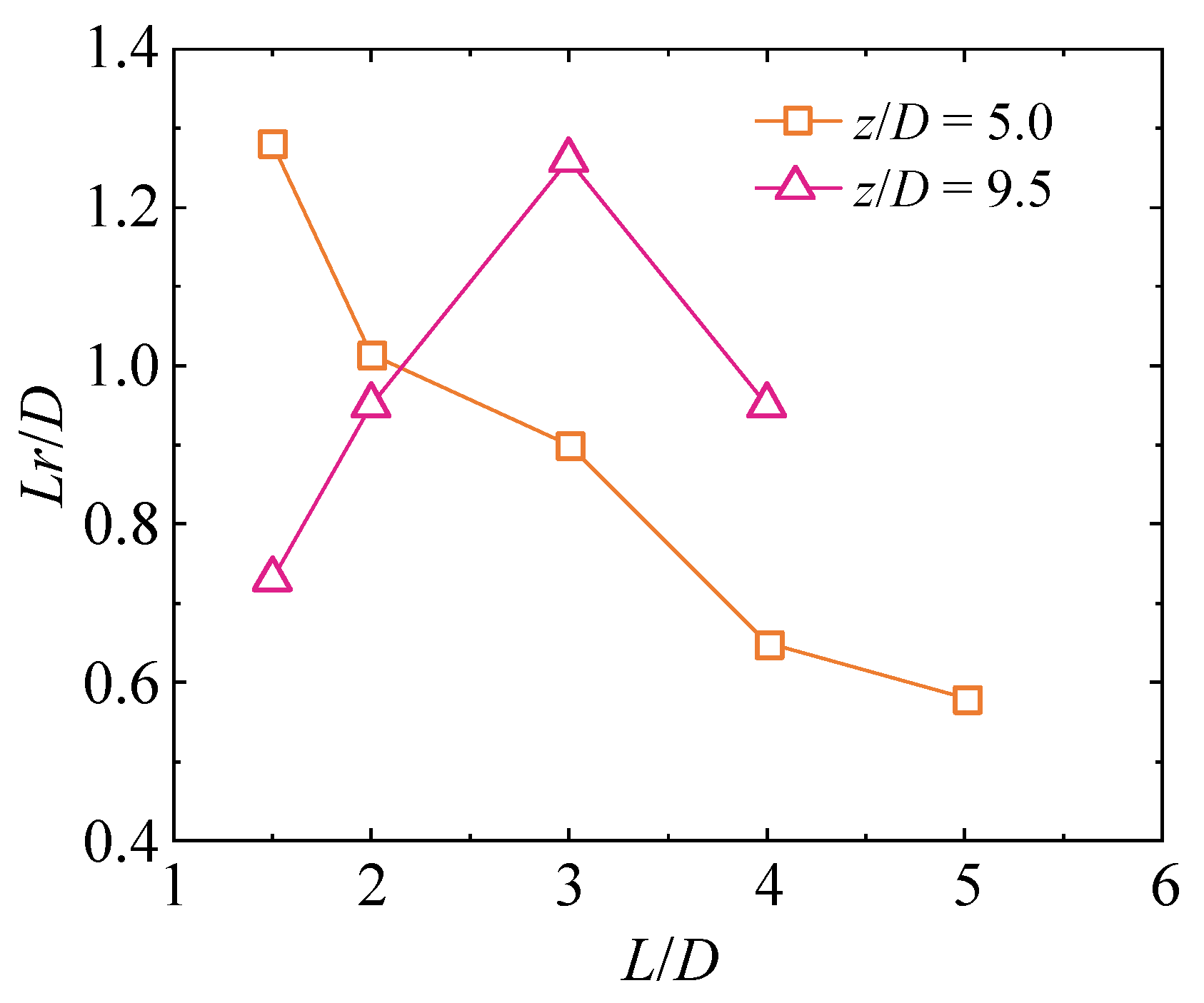
The streamwise extent of the recirculation vortices observed in Figure 4 and Figure 5 can be quantified by the recirculation length Lr. It is defined as the length along the wake centerline downstream of the cylinder over which the time-averaged streamwise velocity remains negative. Figure 7 shows the dependence of the recirculation length downstream of the cylinder C2 on the gap ratio L/D. As noted earlier, on the z = 5D plane, the recirculation region downstream of C1 fills the entire gap. Whereas on the z = 9.5D plane, the length of the reverse-flow region downstream of C1 is nearly constant (approximately 0.5D, as shown in Figure 6b). Therefore, only the recirculation length of C2 is presented here. On the z = 5D plane, the recirculation length downstream of the cylinder C2 decreases monotonically with increasing L/D, in agreement with the experimental observations of Zhang et al. [15] for infinitely long tandem cylinders. This behavior is closely related to the shielding effect of the upstream cylinder and will be further explained in terms of the variation in boundary-layer separation angles with L/D in Section 3.2. On the z = 9.5D plane, under the influence of the strong downwash, recirculation vortices are present only for L/D = 1.5–4. And their lengths exhibit a non-monotonic dependence on L/D, attaining a maximum at L/D = 3.
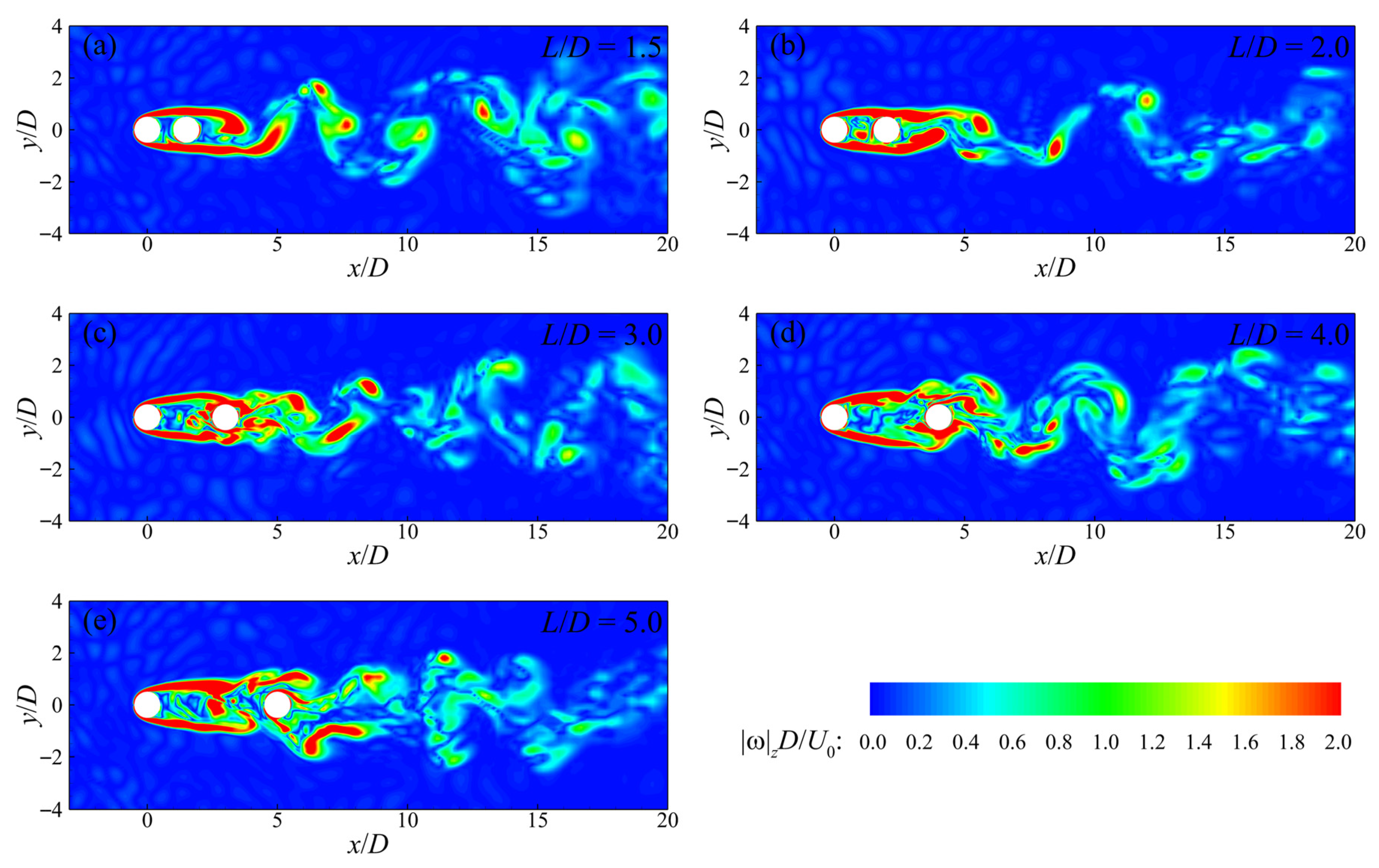
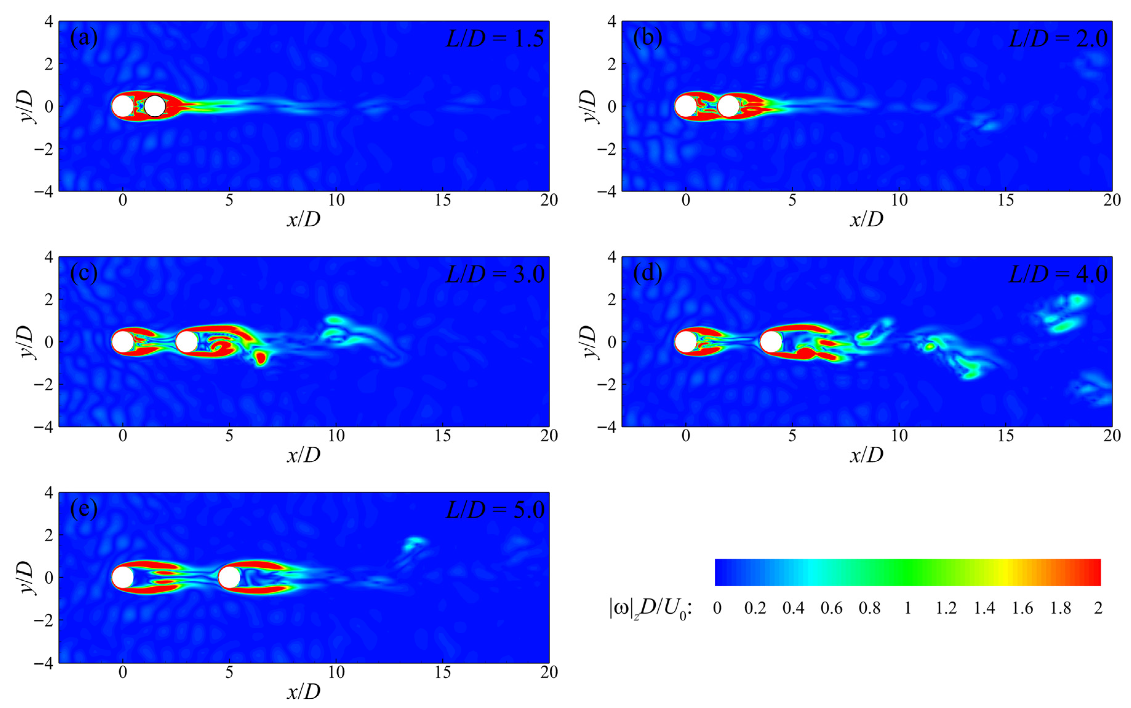
Figure 8 presents instantaneous contours of the magnitude of the vertical vorticity on the horizontal plane at z = 5D, which clearly illustrate the transient wake vortex shedding characteristics of C1 and C2. As shown in the figure, within the range of gap ratios considered in the present study, only two wake regimes—namely the extended-body regime and the reattachment regime—are observed on this plane. For L/D = 1.5, the laterally separated shear layers form on both shoulders of C1 and extend downstream to a certain distance past C2, where they interact and generate periodically alternating vortex shedding. Under this condition, the tandem-cylinder system behaves similarly to an elliptic cylinder. For L/D = 2, the vortex shedding pattern is essentially the same as that for L/D = 1.5, and both cases belong to the extended-body regime. However, for L/D = 2, the onset location of vortex shedding downstream of C2 is closer to the upstream direction, that is, the distance between the shedding location and the trailing edge of C2 is shorter. This is because the increased gap ratio occupies a larger portion of the development region of the separated shear layers from C1.
For L/D = 3–5, the wake pattern corresponds to the reattachment regime. The separated shear layers from C1 reattach onto the surface of C2 before interacting with each other. The reattachment point shifts slightly upstream with increasing L/D. Periodic vortex shedding then occurs downstream of the cylinder C2. Similarly to the extended-body regime shown in Figure 8a,b, in the reattachment regime the distance between the vortex shedding location and C2 also decreases with increasing L/D. However, the wake vortex structures in the reattachment regime are noticeably more complex. It is noteworthy that, although the cases of L/D = 4 and 5 fall within the reattachment regime, secondary gap vortices formed by the premature breakdown of the separated shear layers from C1 are observed in the gap region. This phenomenon is an important indicator of the transition from the reattachment regime toward the co-shedding regime [14]. Moreover, for L/D = 5, the strong interaction between these secondary gap vortices and C2. This interaction is manifested as localized regions of high vorticity within the gap region in Figure 8e. It severely interferes with the wake vortex shedding behind C2, resulting in a wake structure that is less distinct than a classical Kármán vortex street. Similar observations were also reported by Zeng et al. [13].
In the LES study of infinitely long tandem cylinders conducted by Zeng et al. [13], L/D = 5 was classified within the co-shedding regime, L/D = 1.5–4 within the reattachment regime, and only L/D = 1.2 within the extended-body regime. The discrepancy between the present results and those of Zeng et al. [13] is likely attributable to the lower Reynolds number considered in the present study. Zhang et al. [15] demonstrated that for a fixed gap ratio, increasing the Reynolds number drives the transition of wake regimes. This progression evolves from a no vortex shedding regime, to a single-body regime, and subsequently to a reattachment regime. In the context of the present study and the work of Zeng et al. [13], the no vortex shedding and single-body regimes corresponds to the extended-body regime. In addition, experimental measurements by Schewe et al. [2] also indicate that wake regimes are jointly governed by the Reynolds number and the gap ratio.
To explore the influence of the free end of finite-length cylinders on the wake vortex shedding modes of the tandem-cylinder system, Figure 9 shows instantaneous contours of the magnitude of the vertical vorticity on the horizontal plane at z = 9.5D. In contrast to the observations on the z = 5D plane, Figure 9 shows that only for L/D = 1.5 does C2 remain enveloped by the separated shear layers of C1, corresponding to the extended-body regime. For L/D = 2, the separated shear layers from C1 make only very weak contact with the upstream face of C2, suggesting a transitional state between the reattachment and co-shedding regimes. For L/D = 3–5, C2 is completely detached from the separated shear layers of C1, exhibiting characteristics of the co-shedding regime. However, except for the case of L/D = 3, no pronounced periodic vortex shedding is observed downstream of the tandem cylinders for the other cases, even though sufficient space is available for shear-layer development in the co-shedding regime. The resulting vertical vorticity distributions bear some resemblance to the no vortex shedding regime reported by Zhang et al. [15]. This behavior is attributed to the strong downwash near the free end of the cylinders. In the co-shedding regime, separated shear layers form on both sides of the upstream and downstream cylinders and extend downstream. However, their lateral interaction is impeded by the strong downwash induced downstream of the free end. Moreover, the strong downwash accelerates wake velocity recovery, thereby suppressing vortex shedding and leading to an apparent absence of vortex formation. It should be emphasized that the vortex-suppressed behavior observed in the present study differs fundamentally from the no vortex shedding regime reported by Zhang et al. [15]. In the present case, the absence of a Kármán vortex street arises from the inhibition of shear-layer interaction by the strong downwash near the cylinder free end, whereas in the study of Zhang et al. [15], its absence results from stable separated shear layers associated with low Reynolds number flows.
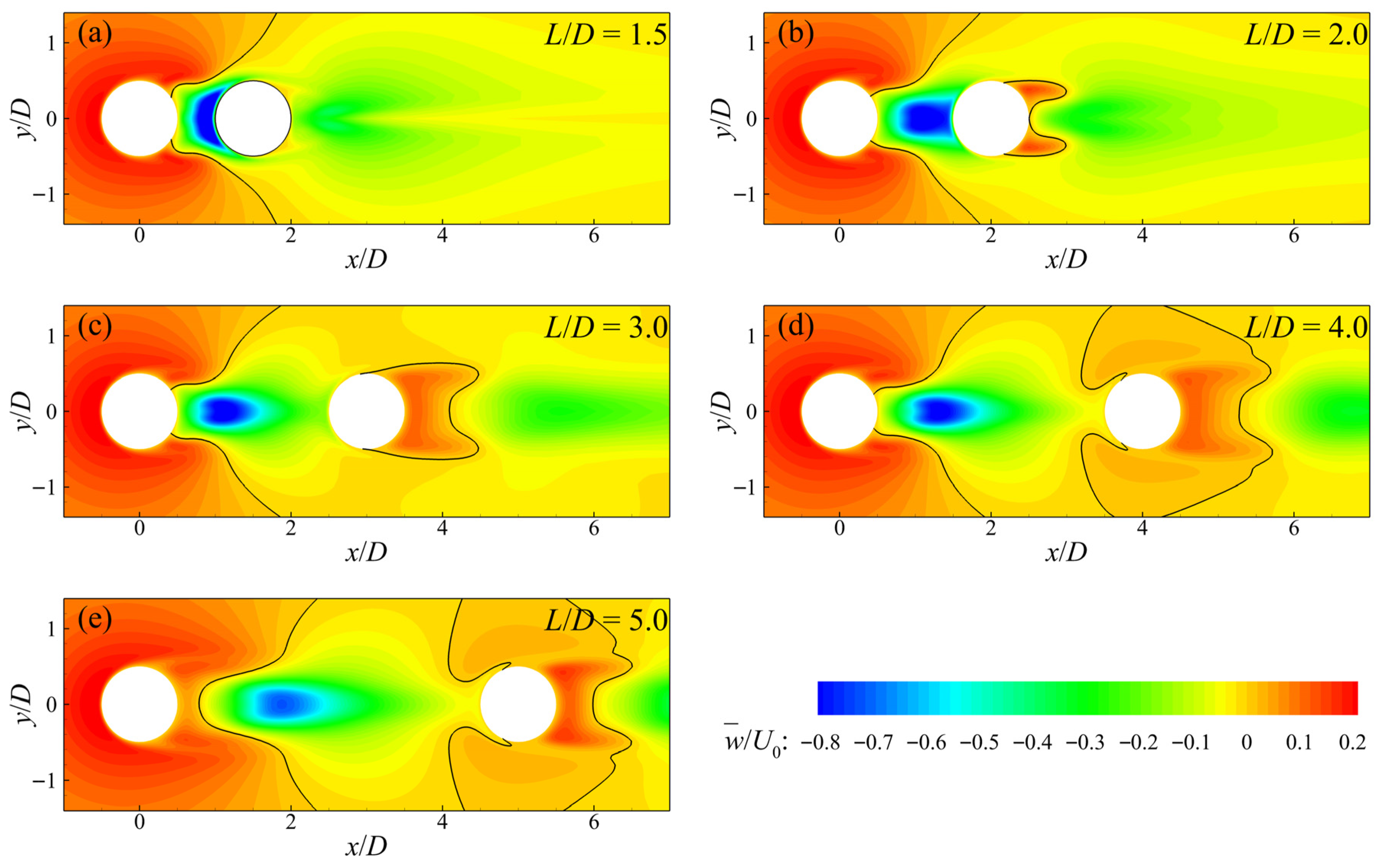
Owing to the presence of the free end, a finite-length cylinder induces upward flow upstream and downwash downstream, as clearly illustrated by the time-averaged vertical velocity distribution on the z = 9.5D plane shown in Figure 10. The upstream upward flow results from the vertical deflection of the incoming flow caused by cylinder blockage, whereas the downstream downwash is induced by vertically oriented recirculation vortices. This also implies that weak upward flow may exist locally in regions immediately adjacent to the downstream face of the cylinder in order to satisfy flow continuity. As shown in Figure 10, the vertical velocity distribution around C1 is similar to that of an isolated cylinder. However, unlike the isolated-cylinder case, except for L/D = 5, no upward flow is observed near the trailing edge of C1 for the other cases. This is because the presence of the downstream cylinder restricts the development of the vertical vortices, rendering their characteristic scales too small (<0.5D) to be intercepted by the z = 9.5D plane. Only when the cylinder spacing is sufficiently large (L/D = 5) do large-scale (>0.5D) vertical vortices develop, giving rise to observable positive vertical velocities.
The vertical velocity distribution in the vicinity of C2 exhibits distinct patterns with increasing L/D. For L/D = 1.5, the downstream cylinder is completely immersed in the wake of the upstream cylinder and is therefore embedded within a region of negative vertical velocity. For L/D = 2–5, vertical vortices are able to form downstream of C2. Consequently, for L/D = 2, weak upward flow begins to appear near the trailing edge of the downstream cylinder, primarily concentrated in the regions of the laterally separated shear layers. As L/D increases, the region of positive vertical velocity progressively expands upstream and intrudes into the gap region. Despite this expansion, the upward flow remains relatively weak, with magnitudes only about 30–40% of those of the adjacent downwash. In other words, for both C1 and C2, the downstream vertical flow is dominated by downwash. The peak magnitude of downwash within the gap region decreases with increasing L/D, attaining a maximum of approximately −1.1U0 at L/D = 1.5 and decreasing to about −0.7U0 at L/D = 5. The location of the strongest downwash also varies with L/D. For L/D = 1.5 and 2, owing to the limited gap width, the peak downwash occurs in the region immediately adjacent to the upstream face of C2. When the gap becomes moderately larger, the peak downwash shifts toward the vicinity of the trailing edge of C1, although the distance between the peak location and the upstream cylinder increases with increasing L/D. Unlike C1, whose upstream face experiences upward flow due to vertical flow deflection, the upstream face of C2 is always subjected to downwash.
For infinitely long cylinders, although the wake structures also exhibit pronounced three-dimensional features, the intensity of the vertical flow is far weaker than the strong downwash induced by the free end of finite-length cylinders. The strong downwash in the wake of the upstream cylinder introduces substantial streamwise momentum, which significantly accelerates momentum recovery within the gap region. This results in more pronounced lateral flow acceleration regions on both sides of C2 than those reported by Zeng et al. [13], as shown in Figure 3.

3.2. Boundary-Layer Separation

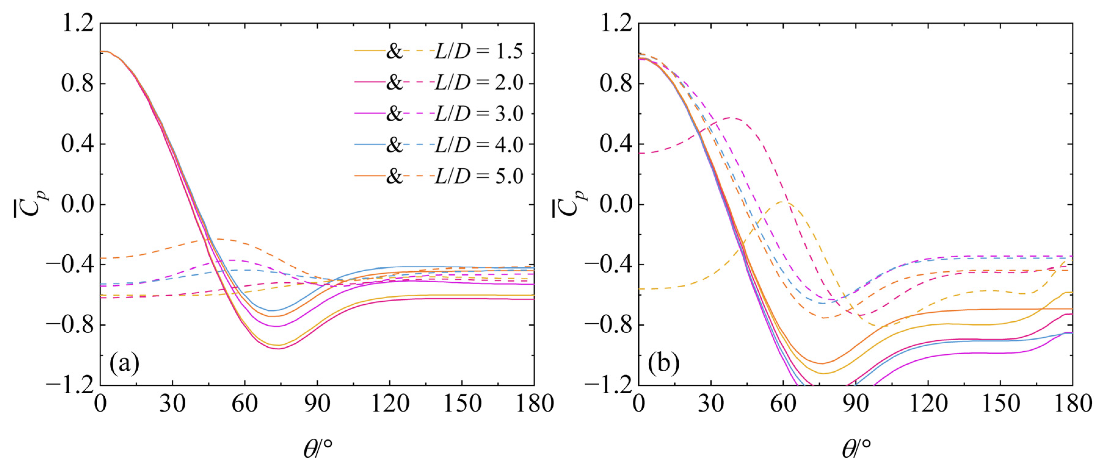
The pressure distribution on the circumferential surface of a cylinder is one of the key parameters governing drag. In this study, the time-averaged pressure coefficient C ¯ p on the surfaces of tandem cylinders at the z = 5D and z = 9.5D planes is computed and shown in Figure 11a and b, respectively. The circumferential coordinate θ denotes the polar angle measured from the upstream stagnation point of the cylinder (θ = 0°). At both z = 5D and z = 9.5D, the shape of the time-averaged pressure coefficient distribution on C1 is essentially identical to that of an isolated cylinder. The only minor difference is that, on the z = 9.5D plane for L/D = 1.5–4, the pressure coefficient of the downstream cylinder slightly increases toward the trailing edge (θ ≥150°). This phenomenon was also observed by Etminan et al. [34] in their study of cylinder arrays and was attributed to the adverse pressure gradient induced by downstream-cylinder blockage. Within the range θ = 0°−30°, the pressure coefficient curves of the upstream cylinder collapse onto a single curve for all L/D cases, consistent with the overlap of the time-averaged streamwise velocity decay curves upstream of the tandem cylinders shown in Figure 6. Overall, the pressure coefficients in the reattachment regime are higher than those in the extended-body regime; however, within a given wake regime, the influence of L/D is not significant, in agreement with Zeng et al. [13]. The location of the negative pressure peak varies only weakly with wake regime and L/D.
For the downstream cylinder, at the z = 5D plane the pressure coefficient remains negative over the entire circumference, first increasing to a peak and then decreasing, which is completely different from the isolated-cylinder case. In the extended-body regime (L/D = 1.5 and 2), no pronounced pressure peak is observed. At the z = 9.5D plane, when L/D = 3–5, the pressure coefficient distribution on C2 closely resembles that of an isolated cylinder, although its overall level is higher than that of an isolated cylinder at the same Reynolds number. This further indicates that, at z = 9.5D and L/D = 3–5, the wake regime has transitioned to the co-shedding regime. For L/D = 1.5, the pressure coefficient on C2 remains negative around the entire circumference, as it is completely enveloped by the separated shear layers from the upstream cylinder. When L/D = 2, the pressure distribution on C2 exhibits characteristics of both the reattachment and co-shedding regimes, although the upstream face has already transitioned to positive pressure.
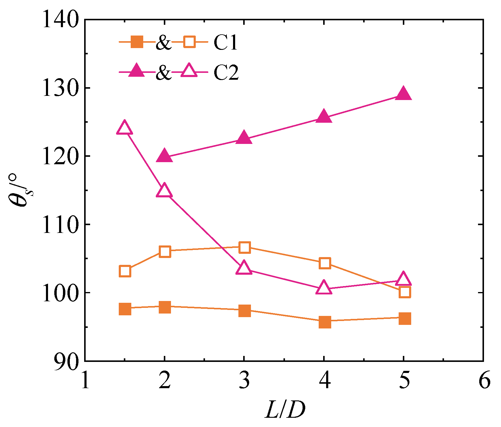
The boundary-layer separation characteristics of the cylinders are quantified by the separation angle θs, as shown in Figure 12. In this study, the separation point is defined as the location along the cylinder surface where the wall shear stress changes sign from positive to negative [34]. For the upstream cylinder, the separation angle on the z = 5D plane shows only a slight decreasing trend with increasing L/D, consistent with Zeng et al. [13]. On the z = 9.5D plane, however, the separation angle first increases and then decreases with increasing L/D, reaching a maximum at L/D = 3. For the downstream cylinder, owing to the distinctly different wake–cylinder interactions at the z = 5D and z = 9.5D planes, the separation angle exhibits different trends with L/D. At the z = 5D plane, the separation angle of C2 increases monotonically with L/D, and consequently the recirculation length Lr decreases with increasing L/D, as shown in Figure 7. For L/D = 1.5, C2 is completely enveloped by the lateral separated shear layers of C1. Consequently, near-zero streamwise wall shear stress is observed only over the upstream-face region (0°−30°), while the remaining surface is dominated by negative shear stress up to approximately 140°. At the z = 9.5D plane, the separation angle of C2 decreases with increasing L/D. Overall, the separation angle of C2 is larger than that of an isolated cylinder, owing to the turbulence introduced by C1, which delays boundary-layer separation on C2.


3.3. Drag Characteristics

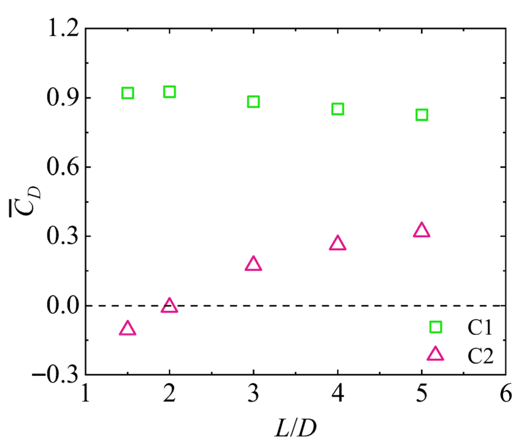
Figure 13 presents the dependence of the overall time-averaged drag coefficient C ¯ D of the upstream and downstream cylinders on the cylinder spacing ratio L/D. The overall time-averaged drag is obtained through a two-step process. First, the viscous and pressure drag components are integrated spatially around the cylinder circumference and over its entire height to yield the instantaneous overall drag force. This instantaneous value is then averaged over time. It is evident that the overall mean drag of C1 and C2 exhibits distinctly different trends with increasing L/D: the former decreases slightly, whereas the latter increases markedly. This behavior is consistent with previous studies on tandem cylinders [11,13,15]. As the spacing increases, the difference gradually diminishes, indicating that the mutual interaction between the cylinders weakens with increasing separation.
As discussed earlier, the wake regime of finite-length tandem cylinders varies in the vertical direction. Near the cylinder free end, the wake regime falls into the co-shedding regime due to the strong downwash, whereas at the mid-height plane of the cylinders it corresponds to the reattachment regime. In both the extended-body and reattachment regimes, C2 is immersed in the recirculation region of C1 and thus experiences a negative approach velocity (as shown in Figure 3 and Figure 4), resulting in negative drag. The extended-body and reattachment regimes therefore contribute negative drag, whereas the co-shedding regime contributes positive drag. For L/D = 1.5, the wake remains in the extended-body regime over the entire cylinder height, leading to a negative C ¯ D value. The pronounced positive values of C ¯ D of C2 for L/D = 3–5 indicate that the overall drag coefficient of the cylinder is dominated by the co-shedding regime. The transition of C ¯ D of C2 from negative to positive occurs at L/D = 2, which is in excellent agreement with the experimental observations of Sumner and Reitenbach [11] for finite-length tandem cylinders with an aspect ratio of 9.

4. Conclusions

This study employed three-dimensional large-eddy simulations (LES) to investigate the flow around finite-length two tandem cylinders. The analysis focuses on the time-averaged and instantaneous flow structures, vortex shedding and boundary-layer separation characteristics, and the overall time-averaged drag coefficients. Five cylinder spacing ratios (L/D = 1.5–5) were considered to examine wake-regimes transitions. Variations in wake regimes and boundary-layer separation characteristics at different vertical planes were also discussed. Bed boundary friction was excluded, so the study concentrates on the hydrodynamic processes near the free end, isolated from bed effects.
At the mid-height plane (z = 5D), when L/D = 1.5 and 2, the wake of the tandem cylinders falls into the extended-body regime. The tandem system behaves like an elongated elliptic cylinder, and periodic vortex shedding occurs at a certain downstream distance behind the downstream cylinder. When L/D = 3–5, the flow transitions to the reattachment regime. In this regime, the length of the recirculation region behind the downstream cylinder decreases monotonically from about 0.99D to 0.58D as L/D increases from 3 to 5, consistent with the increase in its boundary-layer separation angle with L/D.
Near the free end (z = 9.5D), the flow characteristics differ markedly. Except for L/D = 1.5, the downstream cylinder encounters a positive approaching flow, and the wake exhibits features of the co-shedding regime for L/D ≥ 2. The wake velocity and circumferential pressure distributions of both the upstream and downstream cylinders resemble those of isolated cylinders. However, strong downwash (with peak velocity magnitudes up to −1.1U0) suppresses the formation of a coherent periodic vortex street. This results in a vertical transition of the dominant wake regime between the mid-height and the free-end regions for L/D = 2–5.
The overall time-averaged drag coefficients of the upstream and downstream cylinders exhibit opposite trends with increasing L/D: the former decreases modestly from approximately 0.92 at L/D = 1.5 to 0.83 at L/D = 5; whereas the latter increases significantly, from about −0.11 to +0.32. The transition of the downstream cylinder drag coefficient from negative to positive occurs at L/D = 2, indicating that for L/D = 3–5 the overall drag coefficient of the cylinder is dominated by the co-shedding regime. The tandem interaction leads to a substantial drag reduction on C2 compared to an isolated cylinder, with the shielding effect being most pronounced at small spacings.
The present findings reveal a distinct vertical partitioning of the wake in finite-length tandem cylinders. At the mid-height, the flow follows classical 2D gap dynamics. In contrast, the free-end region is dominated by downwash, which shifts the flow toward the co-shedding regime while simultaneously suppressing its full development. This vertical transition underscores the limitation of applying two-dimensional regime classifications to finite-length systems and offers a refined physical basis for modeling interference in analogous 3D configurations like vegetation. Future work should integrate the detailed mechanisms responsible for these regime transitions, as well as the associated variations in local drag coefficients along the cylinder height. Moreover, future numerical simulations should consider adopting the latest numerical schemes to accelerate the solution efficiency of unsteady vortex-shedding dynamics around circular cylinders [25,26].

Author Contributions

Conceptualization, M.L. and Y.W.; methodology, M.L.; Software, M.L.; Validation, M.L. and Y.W.; Formal analysis, M.L.; Investigation, Y.W.; Resources, Y.W.; Data curation, M.L.; Writing—original draft preparation, M.L.; Writing—review and editing, Y.W.; Funding acquisition, M.L. and Y.W. All authors have read and agreed to the published version of the manuscript.

Funding

This work was supported by the National Natural Science Foundation of China [Grant number 52309088, 52409082], the China Postdoctoral Science Foundation [Grant number 2025M773165], the Central Public-Interest Scientific Institution Basal Research Fund (Grant number CKSF2025690/HL).

Data Availability Statement

The original contributions presented in this study are included in the article. Further inquiries can be directed to the corresponding author.

Conflicts of Interest

The authors declare no conflicts of interest.

References

  1. Heydari, S.; Jaiman, R.K. Flow-Induced Vibration of a Flexible Cantilever in Tandem Configuration. Phys. Rev. Fluids 2025, 10, 024701. [Google Scholar] [CrossRef]
  2. Schewe, G.; van Hinsberg, N.P.; Jacobs, M. Investigation of the Steady and Unsteady Forces Acting on a Pair of Circular Cylinders in Crossflow up to Ultra-High Reynolds Numbers. Exp. Fluids 2021, 62, 176. [Google Scholar] [CrossRef]
  3. Han, P.; de Langre, E.; Thompson, M.C.; Hourigan, K.; Zhao, J. Vortex-Induced Vibration Forever Even with High Structural Damping. J. Fluid Mech. 2023, 962, A13. [Google Scholar] [CrossRef]
  4. Aasland, T.E.; Pettersen, B.; Andersson, H.I.; Jiang, F. Revisiting the Reattachment Regime: A Closer Look at Tandem Cylinder Flow at Re=10000. J. Fluid Mech. 2022, 953, A18. [Google Scholar] [CrossRef]
  5. Zhou, J.; Venayagamoorthy, S.K. Near-Field Mean Flow Dynamics of a Cylindrical Canopy Patch Suspended in Deep Water. J. Fluid Mech. 2019, 858, 634–655. [Google Scholar] [CrossRef]
  6. Wang, M.; Mi, S.; Avital, E.; Li, N.; Chen, Y.; Williams, J. A Study on the Influence of Submergence Ratio on the Transport of Suspended Sediment in a Partially Vegetated Channel Flow. Water Resour. Res. 2023, 59, e2022WR032876. [Google Scholar] [CrossRef]
  7. Hu, X.; Zhang, X.; You, Y. On the Flow around Two Circular Cylinders in Tandem Arrangement at High Reynolds Numbers. Ocean Eng. 2019, 189, 106301. [Google Scholar] [CrossRef]
  8. Skonecki, G.M.; Buick, J.M. Numerical Study of Flow around Two Circular Cylinders in Tandem, Side-by-Side and Staggered Arrangements. Fluids 2023, 8, 148. [Google Scholar] [CrossRef]
  9. Zdravkovich, M.M. The Effects of Interference Between Circular Cylinders in Cross Flow†. J. Fluids Struct. 1987, 1, 239–261. [Google Scholar] [CrossRef]
  10. Zdravkovich, M.M. REVIEW—Review of Flow Interference Between Two Circular Cylinders in Various Arrangements. J. Fluids Eng. 1977, 99, 618–633. [Google Scholar] [CrossRef]
  11. Sumner, D.; Reitenbach, H.K. Wake Interference Effects for Two Finite Cylinders: A Brief Review and Some New Measurements. J. Fluids Struct. 2019, 89, 25–38. [Google Scholar] [CrossRef]
  12. Igarashi, T. Characteristics of the Flow around Two Circular Cylinders Arranged in Tandem: 1st Report. Bull. JSME 1981, 24, 323–331. [Google Scholar] [CrossRef]
  13. Zeng, C.; Zhang, Y.; Qiu, F.; Zhou, J.; Wang, L. Large Eddy Simulation of Flow around Two Tandem Circular Cylinders at a Reynolds Number of 3900. Phys. Fluids 2025, 37, 045146. [Google Scholar] [CrossRef]
  14. Zeng, C.; Hu, Y.; Zhou, J.; Wang, L. On the Bi-Stability of Flow around Two Tandem Circular Cylinders at a Subcritical Reynolds Number of 3900. Phys. Fluids 2024, 36, 105128. [Google Scholar] [CrossRef]
  15. Zhang, X.-F.; Yang, J.-C.; Ni, M.-J.; Zhang, N.-M.; Yu, X.-G. Experimental and Numerical Studies on the Three-Dimensional Flow around Single and Two Tandem Circular Cylinders in a Duct. Phys. Fluids 2022, 34, 033610. [Google Scholar] [CrossRef]
  16. Liu, M.; Huai, W.; Ji, B. Characteristics of the Flow Structures through and around a Submerged Canopy Patch. Phys. Fluids 2021, 33, 035144. [Google Scholar] [CrossRef]
  17. Sumner, D.; Rostamy, N.; Bergstrom, D.J.; Bugg, J.D. Influence of Aspect Ratio on the Flow above the Free End of a Surface-Mounted Finite Cylinder. Int. J. Heat Fluid Flow 2015, 56, 290–304. [Google Scholar] [CrossRef]
  18. Sumner, D. Flow above the Free End of a Surface-Mounted Finite-Height Circular Cylinder: A Review. J. Fluids Struct. 2013, 43, 41–63. [Google Scholar] [CrossRef]
  19. Lee, T.; Lin, C.L.; Friehe, C.A. Large-Eddy Simulation of Air Flow around a Wall-Mounted Circular Cylinder and a Tripod Tower. J. Turbul. 2007, 8, N29. [Google Scholar] [CrossRef]
  20. Fröhlich, J.; Rodi, W. LES of the Flow around a Circular Cylinder of Finite Height. Int. J. Heat Fluid Flow 2004, 25, 537–548. [Google Scholar] [CrossRef]
  21. Luo, S.C.; Gan, T.L.; Chew, Y.T. Uniform Flow Past One (or Two in Tandem) Finite Length Circular Cylinder(s). J. Wind Eng. Ind. Aerodyn. 1996, 59, 69–93. [Google Scholar] [CrossRef]
  22. Wang, M.; Zhang, W.; Wang, W.; Wan, D. Impact of Tandem on Flow Characteristics Around Surface-Piercing Finite Circular Cylinders; OnePetro: Goyang, Republic of Korea, 2025; p. ISOPE-I-25-372. [Google Scholar]
  23. Kim, T.; Christensen, K.T. Flow Interactions Between Streamwise-Aligned Tandem Cylinders in Turbulent Channel Flow. AIAA J. 2018, 56, 1421–1433. [Google Scholar] [CrossRef]
  24. Palau-Salvador, G.; Stoesser, T.; Rodi, W. LES of the Flow around Two Cylinders in Tandem. J. Fluids Struct. 2008, 24, 1304–1312. [Google Scholar] [CrossRef]
  25. Deng, X. A Unified Framework for Non-Linear Reconstruction Schemes in a Compact Stencil. Part 1: Beyond Second Order. J. Comput. Phys. 2023, 481, 112052. [Google Scholar] [CrossRef]
  26. Deng, X. A New Open-Source Library Based on Novel High-Resolution Structure-Preserving Convection Schemes. J. Comput. Sci. 2023, 74, 102150. [Google Scholar] [CrossRef]
  27. Liu, M.; Huai, W.; Ji, B.; Han, P. Numerical Study on the Drag Characteristics of Rigid Submerged Vegetation Patches. Phys. Fluids 2021, 33, 085123. [Google Scholar] [CrossRef]
  28. Zong, L.; Nepf, H. Vortex Development behind a Finite Porous Obstruction in a Channel. J. Fluid Mech. 2012, 691, 368–391. [Google Scholar] [CrossRef]
  29. Tanino, Y.; Nepf, H.M. Lateral Dispersion in Random Cylinder Arrays at High Reynolds Number. J. Fluid Mech. 2008, 600, 339–371. [Google Scholar] [CrossRef]
  30. Nicoud, F.; Ducros, F. Subgrid-Scale Stress Modelling Based on the Square of the Velocity Gradient Tensor. Flow Turbul. Combust. 1999, 62, 183–200. [Google Scholar] [CrossRef]
  31. Gong, Y.; Stoesser, T.; Mao, J.; McSherry, R. LES of Flow Through and Around a Finite Patch of Thin Plates. Water Resour. Res. 2019, 55, 7587–7605. [Google Scholar] [CrossRef]
  32. Ouro, P.; Juez, C.; Franca, M. Drivers for Mass and Momentum Exchange between the Main Channel and River Bank Lateral Cavities. Adv. Water Resour. 2020, 137, 103511. [Google Scholar] [CrossRef]
  33. Liu, M.; Huai, W.; Tang, H.; Wang, Y.; Yuan, S. Numerical Study of Mean and Turbulent Flow Adjustments in Open Channels with Limited Near-Bank Vegetation Patches. Phys. Fluids 2024, 36, 095117. [Google Scholar] [CrossRef]
  34. Etminan, V.; Lowe, R.J.; Ghisalberti, M. A New Model for Predicting the Drag Exerted by Vegetation Canopies. Water Resour. Res. 2017, 53, 3179–3196. [Google Scholar] [CrossRef]
  35. Liu, D.; Diplas, P.; Fairbanks, J.D.; Hodges, C.C. An Experimental Study of Flow through Rigid Vegetation. J. Geophys. Res. Earth Surf. 2008, 113, 1–16. [Google Scholar] [CrossRef]
  36. Liu, M.; Wang, Y.; Gong, Y.; Wang, S. 2D-URANS Study on the Impact of Relative Diameter on the Flow and Drag Characteristics of Circular Cylinder Arrays. Water 2024, 16, 2264. [Google Scholar] [CrossRef]
  37. Jethani, Y.; Kumar, K.; Sameen, A.; Mathur, M. Local Origin of Mode-B Secondary Instability in the Flow Past a Circular Cylinder. Phys. Rev. Fluids 2018, 3, 103902. [Google Scholar] [CrossRef]
  38. Lehmkuhl, O.; Rodríguez, I.; Borrell, R.; Oliva, A. Low-Frequency Unsteadiness in the Vortex Formation Region of a Circular Cylinder. Phys. Fluids 2013, 25, 085109. [Google Scholar] [CrossRef]
  39. Nepf, H.M. Flow and Transport in Regions with Aquatic Vegetation. Annu. Rev. Fluid Mech. 2012, 44, 123–142. [Google Scholar] [CrossRef]
  40. Huai, W.; Li, S.; Katul, G.G.; Liu, M.; Yang, Z. Flow Dynamics and Sediment Transport in Vegetated Rivers: A Review. J. Hydrodyn. 2021, 33, 400–420. [Google Scholar] [CrossRef]
  41. Zeng, C.; Qiu, F.; Zhou, J.; Hu, Y.; Wang, L. Large Eddy Simulation of Flow around Two Side-by-Side Circular Cylinders at Reynolds Number 3900. Phys. Fluids 2023, 35, 035102. [Google Scholar] [CrossRef]
  42. Pattenden, R.J.; Bressloff, N.W.; Turnock, S.R.; Zhang, X. Unsteady Simulations of the Flow around a Short Surface-Mounted Cylinder. Int. J. Numer. Methods Fluids 2007, 53, 895–914. [Google Scholar] [CrossRef]
Figure 1. Computational domain schematic: (a) 3D view; (b) planar computational grid.
Water 18 00305 g001
Figure 2. Time-averaged streamwise velocity contours at the z = 5D plane (black solid lines denote the zero-velocity contour, white circle represents a solid cylinder). (a) L/D = 1.5; (b) L/D = 2.0; (c) L/D = 3.0; (d) L/D = 4.0; (e) L/D = 5.0.
Water 18 00305 g002
Figure 3. Time-averaged streamwise velocity contours at the z = 9.5D plane (black solid lines denote the zero-velocity contour). (a) L/D = 1.5; (b) L/D = 2.0; (c) L/D = 3.0; (d) L/D = 4.0; (e) L/D = 5.0.
Water 18 00305 g003
Figure 4. Two-dimensional time-averaged streamlines at the z = 5D plane. (a) L/D = 1.5; (b) L/D = 2.0; (c) L/D = 3.0; (d) L/D = 4.0; (e) L/D = 5.0.
Water 18 00305 g004
Figure 5. Two-dimensional time-averaged streamlines at the z = 9.5D plane. (a) L/D = 1.5; (b) L/D = 2.0; (c) L/D = 3.0; (d) L/D = 4.0; (e) L/D = 5.0.
Water 18 00305 g005
Figure 6. Distributions of time-averaged streamwise velocity along the wake centerline: (a) z = 5D; (b) z = 9.5D (the shaded region indicates the location of C1).
Water 18 00305 g006
Figure 7. Variation in the recirculation length of the downstream cylinder C2 with the cylinder spacing ratio.
Water 18 00305 g007
Figure 8. Instantaneous contours of the magnitude of vertical vorticity at the z = 5D plane. (a) L/D = 1.5; (b) L/D = 2.0; (c) L/D = 3.0; (d) L/D = 4.0; (e) L/D = 5.0.
Water 18 00305 g008
Figure 9. Instantaneous contours of the magnitude of vertical vorticity at the z = 9.5D plane. (a) L/D = 1.5; (b) L/D = 2.0; (c) L/D = 3.0; (d) L/D = 4.0; (e) L/D = 5.0.
Water 18 00305 g009
Figure 10. Time-averaged vertical velocity contours at the z = 9.5D plane (black solid lines denote the zero-velocity contour). (a) L/D = 1.5; (b) L/D = 2.0; (c) L/D = 3.0; (d) L/D = 4.0; (e) L/D = 5.0.
Water 18 00305 g010
Figure 11. Circumferential distributions of the time-averaged pressure coefficient: (a) z = 5D; (b) z = 9.5D (solid lines denote C1, dashed lines denote C2).
Water 18 00305 g011
Figure 12. Variation in the separation angle with the cylinder spacing ratio (solid symbols denote the z = 5D plane, open symbols denote the z = 9.5D plane).
Water 18 00305 g012
Figure 13. Variation in the overall time-averaged drag coefficient of the cylinders with the cylinder spacing ratio.
Water 18 00305 g013
Disclaimer/Publisher’s Note: The statements, opinions and data contained in all publications are solely those of the individual author(s) and contributor(s) and not of MDPI and/or the editor(s). MDPI and/or the editor(s) disclaim responsibility for any injury to people or property resulting from any ideas, methods, instructions or products referred to in the content.