Article

Geophysical and Geochemical Pilot Study to Characterize the Dam Foundation Rock and Source of Seepage in Part of Pensacola Dam in Oklahoma

Boone Pickens School of Geology, Oklahoma State University, 105 Noble Research Center, Stillwater, OK 74078, USA
*
Author to whom correspondence should be addressed.
Water 2023, 15(23), 4036; https://doi.org/10.3390/w15234036
Submission received: 23 October 2023 / Revised: 5 November 2023 / Accepted: 14 November 2023 / Published: 21 November 2023
(This article belongs to the Special Issue Groundwater Exploration and Hydrogeophysical Research)

Abstract

:
Pensacola Dam, operated by the Grand River Dam Authority (GRDA), is a multiple-arch buttress dam constructed in 1940. The dam has little or no existing geophysical reports on the integrity of the dam foundation rock and even less knowledge at depth. Visual inspection indicated evidence of seepage at some arches of the dam. As a pilot study, we conducted a suite of geophysical surveys inside two arches (Arch-16 and Arch-17) and a part of the downstream berm to characterize the dam foundation rock, delineate seepage zones, and identify the most appropriate geophysical methods for temporal monitoring of the dam’s conditions. The geophysical methods included electrical resistivity tomography (ERT), self-potential (SP), multichannel analysis of surface waves (MASW), compressional (P)-wave refraction, and shear (S)-wave reflection. Water samples were collected for geochemical analysis to investigate the source of the seepage flow inside Arch-16. The geophysical results characterized the dam foundation rock into an unsaturated limestone and chert overlying a water-saturated limestone and chert. The ERT profiles indicated that groundwater is rising inside the arches and significantly dropping under the downstream berm, which can be due to the uplift pressure beneath the dam base. Zones of high seepage potential were detected near the buttress walls of the two surveyed arches, which may be related to previous blasting, excavation of the dam foundation, concrete placement, or improper grouting. The geochemical analysis of water samples taken from the artesian wells inside Arch-16 and the Grand Lake revealed different chemical compositions, suggesting that the source of water could be a mixture of groundwater and lake water or lake water interacting with rock and reaching the surface through fractures; however, more sampling and further analysis are required to ascertain the source of the seeps. This study showed that the ERT, SP, and S-wave reflection methods have effectively characterized the dam foundation rock and seepage zones beneath the arches. The study provided a better understanding of the conditions of the dam foundation rock, evaluated the utilized geophysical methods, and determined the optimum geophysical methods that can be used for the characterization and monitoring of the subsurface conditions along the entire length of the dam. In this study, we have demonstrated that the integration of effective geophysical surveys and geochemical analysis yielded optimum results in solving a complex dam safety problem. This strategy promotes the best practice for dam safety investigation.

1. Introduction

The Pensacola Dam, operated by the Grand River Dam Authority (GRDA), is a multiple-arch buttress dam located in the northeastern part of Oklahoma within the Ozark Uplift. The dam was constructed in 1940, and it is widely thought to be the longest multiple-arch dam ever made. It was built to create hydroelectric power, control floods, and provide recreational amenities to the people of Oklahoma and the United States. The value of the Pensacola Dam cannot be overstated; its importance to Oklahoma and the country as a whole is truly immense. A recent report from the dam authority indicates that the foundation rock at several arches (especially Arch-16) and buttress walls have exhibited chronic seepage post flooding events [1].
Seepage can be a chronic maintenance nuisance causing loss of water from the reservoir, potential weakening, degradation, or erosion of the dam foundation. If seepage is excessive and continues for decades, it may eventually lead to dam failures [2,3,4,5]. Moreover, there is no geophysical information about the dam and the dam has relatively minimal spatial confirmation of the dam foundation rock at the contact of the dam foundation. Therefore, there is a need to better characterize the foundation rock at the dam and develop a predictive monitoring plan that would provide reliable information about the seepage progression and corresponding deterioration conditions.
Geophysical methods have been established as non-invasive tools for the characterization of seepage zones and dam foundations [6,7,8,9,10,11,12,13]. Geophysical methods measure variations in the physical properties of the subsurface to evaluate geological, hydrological, and engineering conditions of the subsurface materials. For instance, the electrical resistivity tomography (ERT) can describe the 2D/3D electrical pattern of the subsurface materials which can be used to infer their geological and hydrological properties. Hence, the method can be used to image and characterize subsurface structures and variations in electrical resistivity [14,15,16,17,18]. Seismic shear-wave velocity measurements can be used to detect zones of potential fractures, deformations in material, and rock dissolution [15,19]. These readings can be incredibly helpful in defining the structure and composition of underground substrata.
Integration of more than one geophysical technique is often useful to constrain the geophysical interpretation and improve subsurface characterization [12,20,21,22,23,24]. The geophysical methods that are often employed include, but are not limited to, electrical resistivity tomography (ERT), induced polarization (IP), self-potential (SP), electromagnetic (EM), multichannel analysis of surface waves (MASW), seismic shear (S)-wave reflection, seismic compressional (P)-wave refraction, and ground penetrating radar (GPR).
ERT can identify low resistivity zones which can be related to the presence of water (allowing for the identification of aquifers, water tables, and groundwater flow patterns), reveal the presence of geological structures (faults, fractures, and bedrock boundaries), and provide valuable information about subsurface porosity and fluid saturation [7,20,25]. ERT can be interpreted in terms of possible air- or water-filled voids and highly saturated volumes, which could be zones of high seepage potential [12,15,26,27,28]. The IP method provides complementary information to other geophysical methods like electrical resistivity, helping to enhance subsurface characterization and understanding by providing valuable information about the presence of polarizable substances and hydrogeological characteristics of the subsurface [29,30]. The SP method is one of the oldest electrical methods, and the most used for the seepage detection pathways in dams [31,32,33]. Variation in SP values along dams often indicates seepage pathways and direction of water flow in the subsurface [5,20,34,35].
S-wave reflection detects alterations in the elastic characteristics of the subsurface materials and their boundaries, such as fractures and dissolutions [36]. The MASW maps variations in the shear-wave velocity (Vs) to infer engineering parameters of the subsurface materials such as stiffness and rigidity [9,15,21,37]. These variations can be used to detect shallow voids and tunnels, map the bedrock surface, and delineate fractures [15,38]. Through the seismic P-wave refraction method, the compressional (P)-wave velocity (Vp) of the subsurface could be measured to determine the bedrock surface’s depth [5,15].
The geochemical analysis of surface and groundwater can be used to determine the origin of water seeps at dams. This analysis relies on the analysis of the chemical composition and concentration of numerous elements and compounds. Analyzing these data can provide valuable information on the source of seeps, as well as any changes over time [39,40,41,42,43] which could help in understanding the fate of seepage, and thus making it possible to implement more effective management practices.
This study is carried out as a pilot study with the aim of evaluating the efficacy of the utilized geophysical methods to characterize the subsurface conditions at Pensacola Dam and providing information on how to best establish a monitoring schedule and baseline. The specific objectives of this study include (i) characterizing the dam foundation rock, (ii) delineating seepage zones at selected parts of the dam, and (iii) determining the possible source of the seeps at Arch-16.

2. Site Description and Geology

The Pensacola Dam is located at the town of Langley in the northeastern part of Oklahoma (Figure 1). The dam is a multiple-arch dam, which comprises three spillways (one main spillway and two auxiliary spillways) and fifty-one arches and buttresses. The dam is about 46 m tall above the riverbed and with a total length of 2001 m. The multiple-arch section of the dam extends along a distance of 1306 m. A drainage ditch runs next to the toes of the arches bounded by a gravel road running parallel to the dam’s axis (Figure 1b). Past the drainage ditch, the downstream berm rises gradually to a 50 m height over a 120 m distance, and then flattens (Figure 1b). Fill materials were placed to construct the downstream berm which acts as a tailwater protection levee. Each arch of the Pensacola Dam has a clear span of 18 m, and its buttresses measure 7.3 m in width (Figure 1c).
The Pensacola Dam is built along the southwestern slopes of the Ozark Uplift, which is a broad asymmetrical dome covering about 103,600 km2 across Missouri, Arkansas, and Oklahoma [44]. The Ozark uplift is bounded by the Mississippi Lowlands to the southeast, the Arkansas Valley to the south, and the Prairie Plains homocline to the northwest [45]. The uplift created faults during the middle Pennsylvanian and the process has caused the rocks along the border of the uplift to be folded and broken [46]. One of the most important faults within the Ozark uplift is the Seneca fault, which has a length of about 160,000 km. The fault starts in Missouri and extends across Ottawa, Delaware, and Mayes Counties in southwest, northwest, and diagonal directions, respectively [47]. The Seneca fault is often referred to as a syncline because it is part of a graben created by two faults [47] and passes a short distance south of the Pensacola Dam, near the middle spillway and northeastward through the reservoir [48].
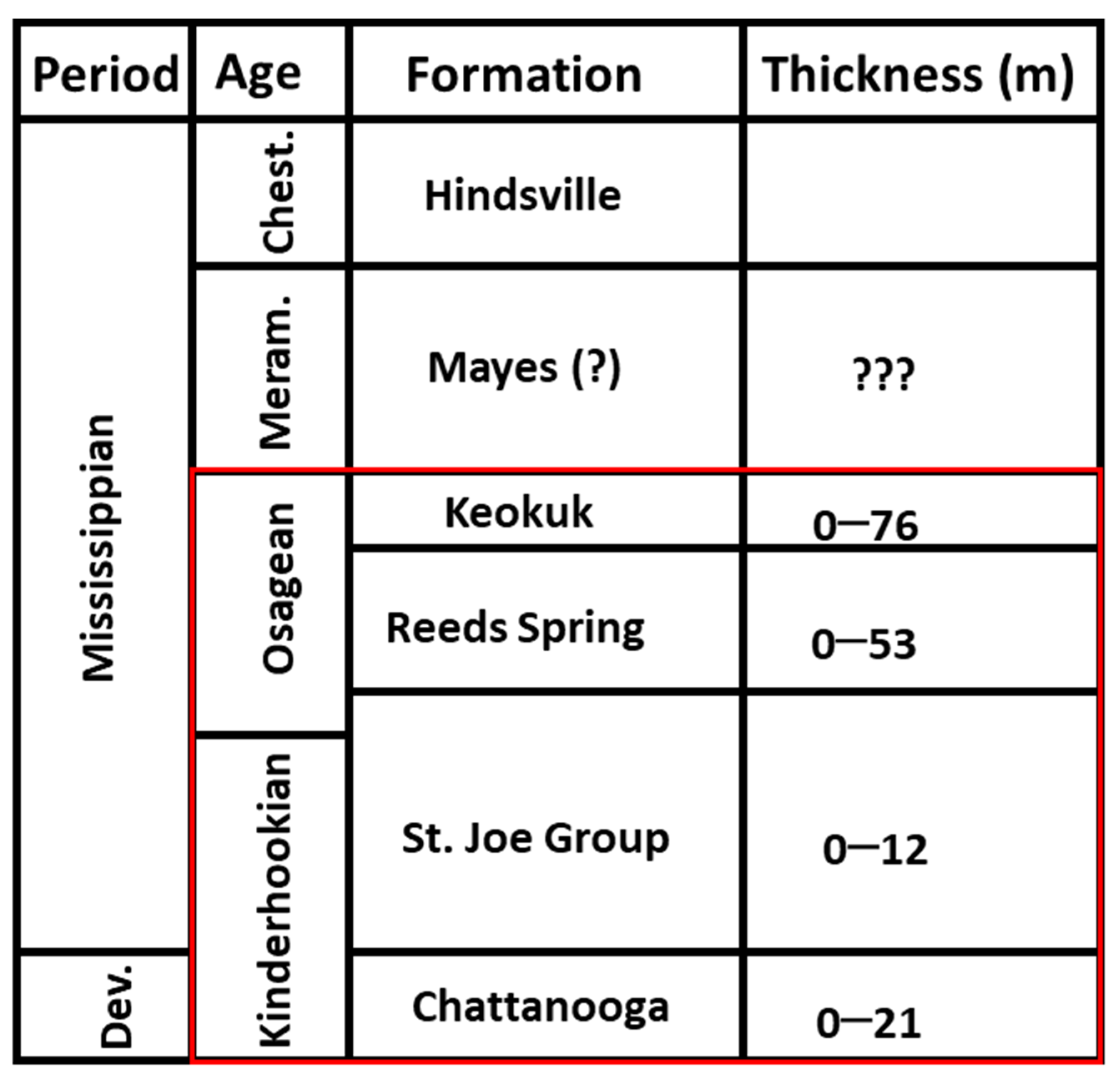
The subsurface in the area of the dam comprises Mississippian-aged rocks including the St. Joe Group, Reeds Spring Formation, and the Keokuk Formation, which are all part of the Boone Group ([45,47]; Figure 2). The St. Joe Group is divided into three units including upper, middle, and basal units. The upper unit of the Pierson Formation comprises around 7.5 m of thick-bedded, gray, fine crystalline limestone. Situated in the middle, the Northview Formation is a two-meter-thick deposit comprising green to gray calcareous shale or marlstone. At its base, the Compton Formation features heavy-bedded limestone that has a gray, nodular-weathering hue [45]. The Reeds Spring Formation also boasts similar properties, containing thin beds of dense, fine-grain limestone and dark to tan, blue-gray chert [45]. Lastly, the Keokuk Formation covers the Reeds Spring Formation in an unconformable fashion, comprising large pieces of white to buff and gray-mottled chert containing fossils, as well as patches of blue-gray, dense, fine-grain limestone. However, at depth, the Devonian-Mississippian aged Chattanooga shale is encountered in some places below the dam. The Chattanooga shale is a dark gray to black shale, which is thin to nearly horizontal-bedded, and has a thickness that ranges from 4.5 to 9 m [48,49]. In certain locations, the shale contains pyrite, phosphate, glauconite, and uranium. The upper few centimeters of this Chattanooga shale are weathered to a greenish gray color [47].
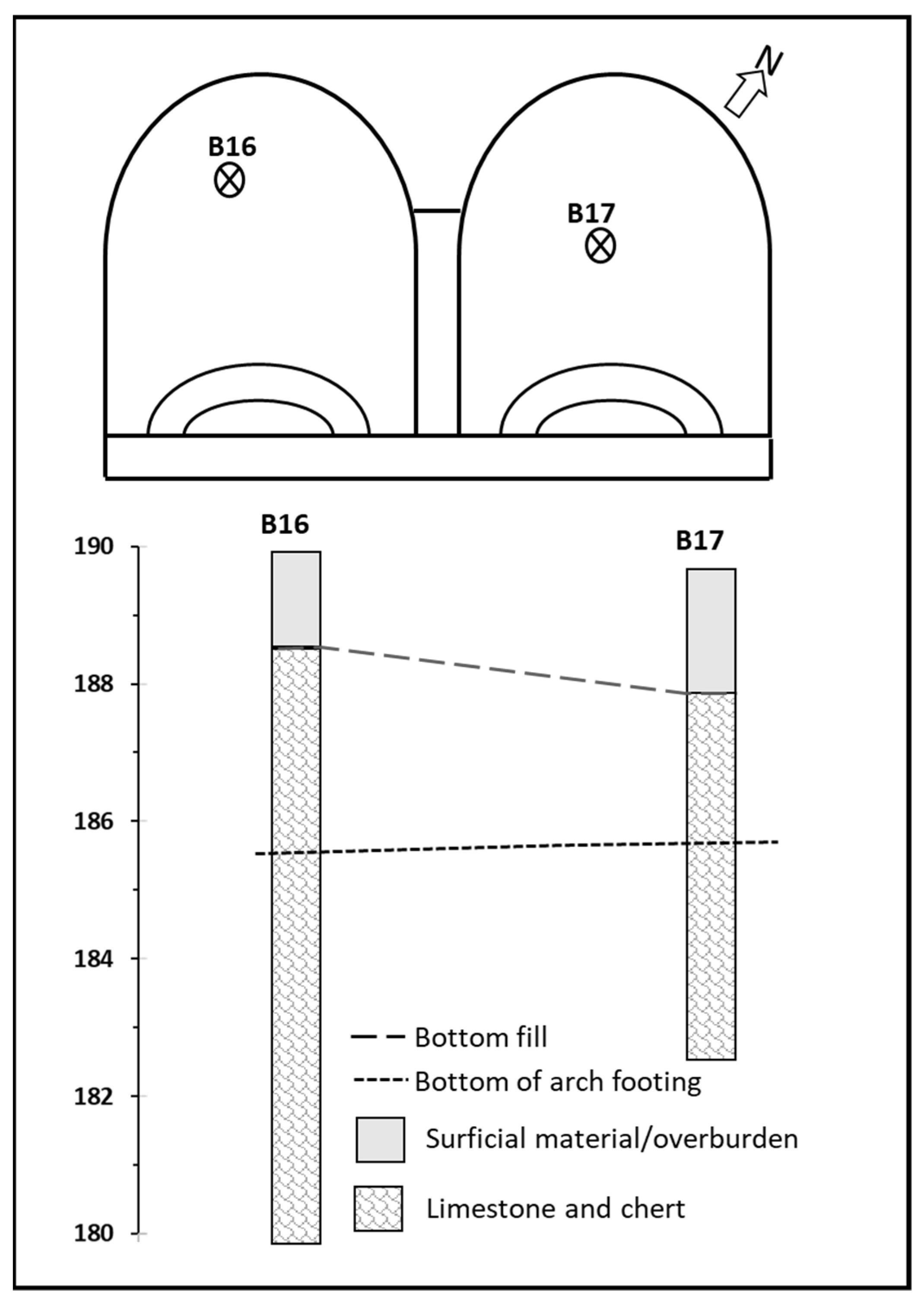
The foundation of the Pensacola Dam rests predominantly on the Reeds Spring Formation, although the Keokuk Formation was encountered at the extreme west end of the dam, adjacent to the powerhouse [50]. Data from drilling reports at Pensacola Dam inside the arches were made available by the GRDA [48]. Two borehole logs from Arch-16 and one borehole log from Arch-17 were provided. The three boreholes (B16, B16A, and B17) were drilled with depths varying between ~7 and 11 m. All the drill holes show that the subsurface beneath the arches comprise two distinct layers: 1.6–1.8 m of thick overburden (surficial materials comprising silt, sand, gravels, cobbles) and foundation rock that contains limestone and chert (Figure 3).
The shallow aquifer in the Pensacola Dam is the Boone aquifer, which comprises the rocks in the Boone Group [47]. The Boone Group comprises the limestone member of the St. Joe Group (base of the aquifer), Reeds Spring Formation, and the Keokuk Formation [47,51]. The Boone aquifer comprises the Mississippian limestone and chert, and thus, it is being regarded as a karst aquifer. Most of the porosities in the Boone aquifer are from solution cavities as well as fractures that occur in the limestone. Outcrop studies have shown that the Boone Group shows characteristics and features such as sinkholes, caves, springs, and disappearing streams that are related to karst aquifers. These characteristics and features make the aquifer display an instant recharge as well as rapid groundwater flow rate due to precipitation events [52].
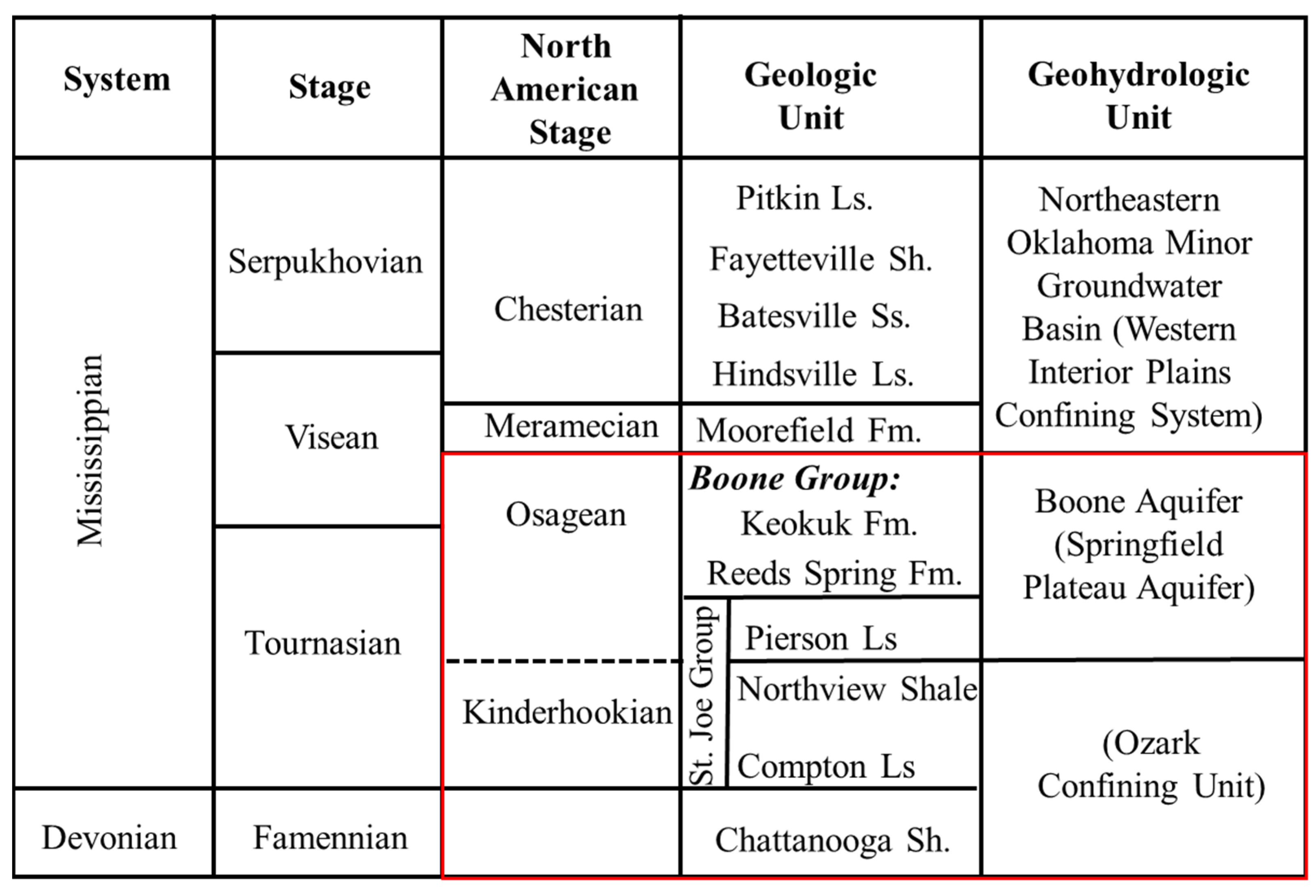
In places where the Boone Group is visible, the recharge to the Boone aquifer mainly comes from precipitation infiltration, which is a rapid process [47,53]. This is due to the widespread dissolution of limestone, presence of fractures, and the relatively thin nature of soil and subsoil in the Ozark region. The Ozark confining unit underneath the Boone aquifer comprises the Northview and Compton Formations of the St. Joe Group and the Chattanooga shale (Figure 4). In some areas where the Chattanooga shale is overlain by the Northview shale and Compton limestone, the Chattanooga shale exhibits low permeability and often acts as an aquitard that impedes the downward movement of water from the Boone aquifer [49]. The Boone aquifer is unconfined and laterally extensive in places where the Boone Group outcrops. However, the rugged terrain and permeability boundaries occurring in the interbedded limestone and chert usually divide the formation into a series of small-scale perched aquifers [52].

3. Geophysical Data Acquisition and Processing

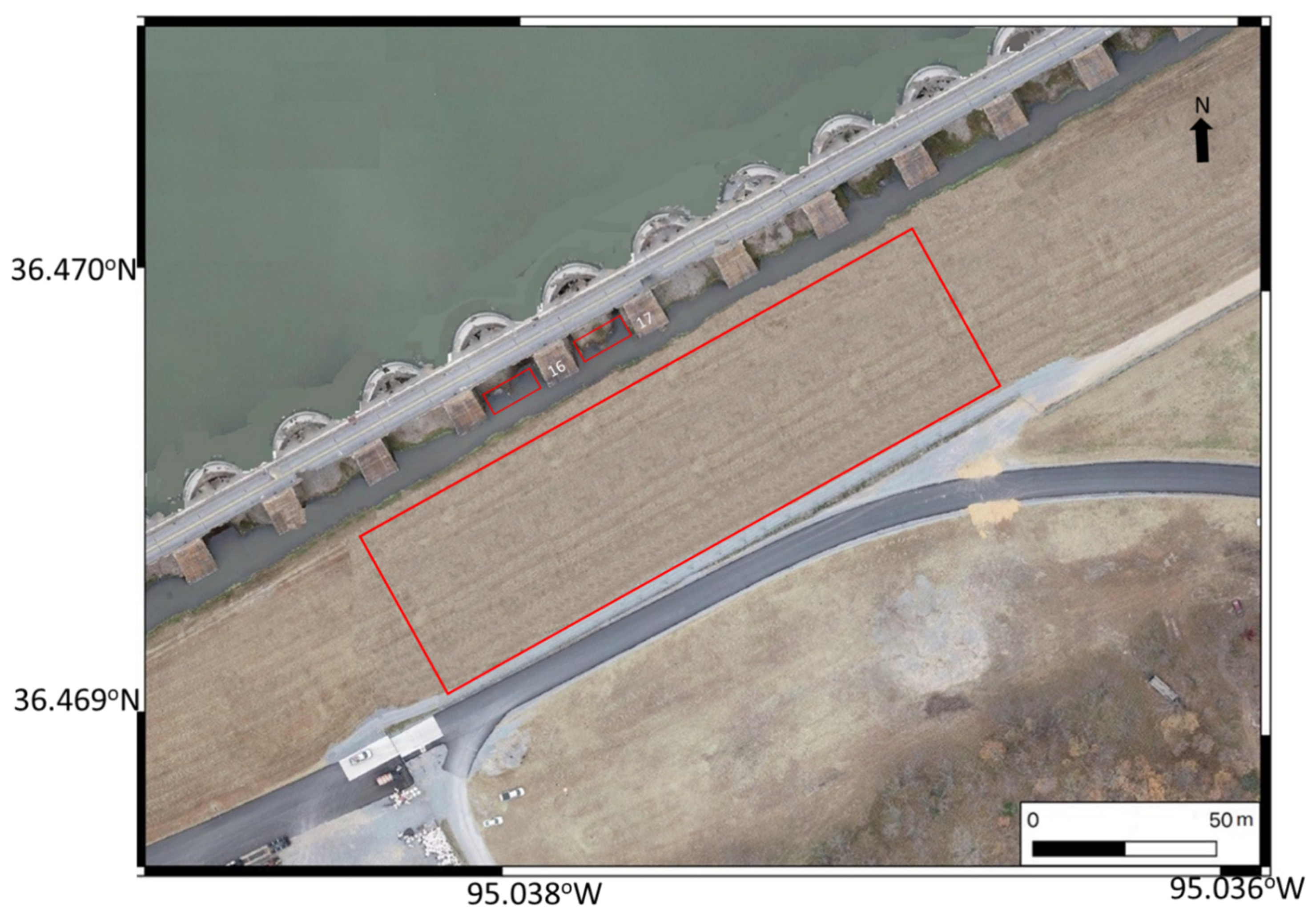
The geophysical surveys were carried out inside two structural arches (Arch-16 and Arch-17) and parts of the downstream berm (Figure 5). Acquired data from the arches and the downstream berm include a total of sixteen ERT profiles, six SP profiles, six seismic P-wave refraction profiles, two MASW profiles, and two S-wave reflection profiles. The geophysical profiles inside Arch-16 and Arch-17 were acquired in a southeast-northwest direction, while the geophysical surveys at the downstream berm were acquired along linear southwest-northeast traverses parallel to the axis of the dam (Figure 5).

3.1. Data Acquisition inside Arch-16 and Arch-17

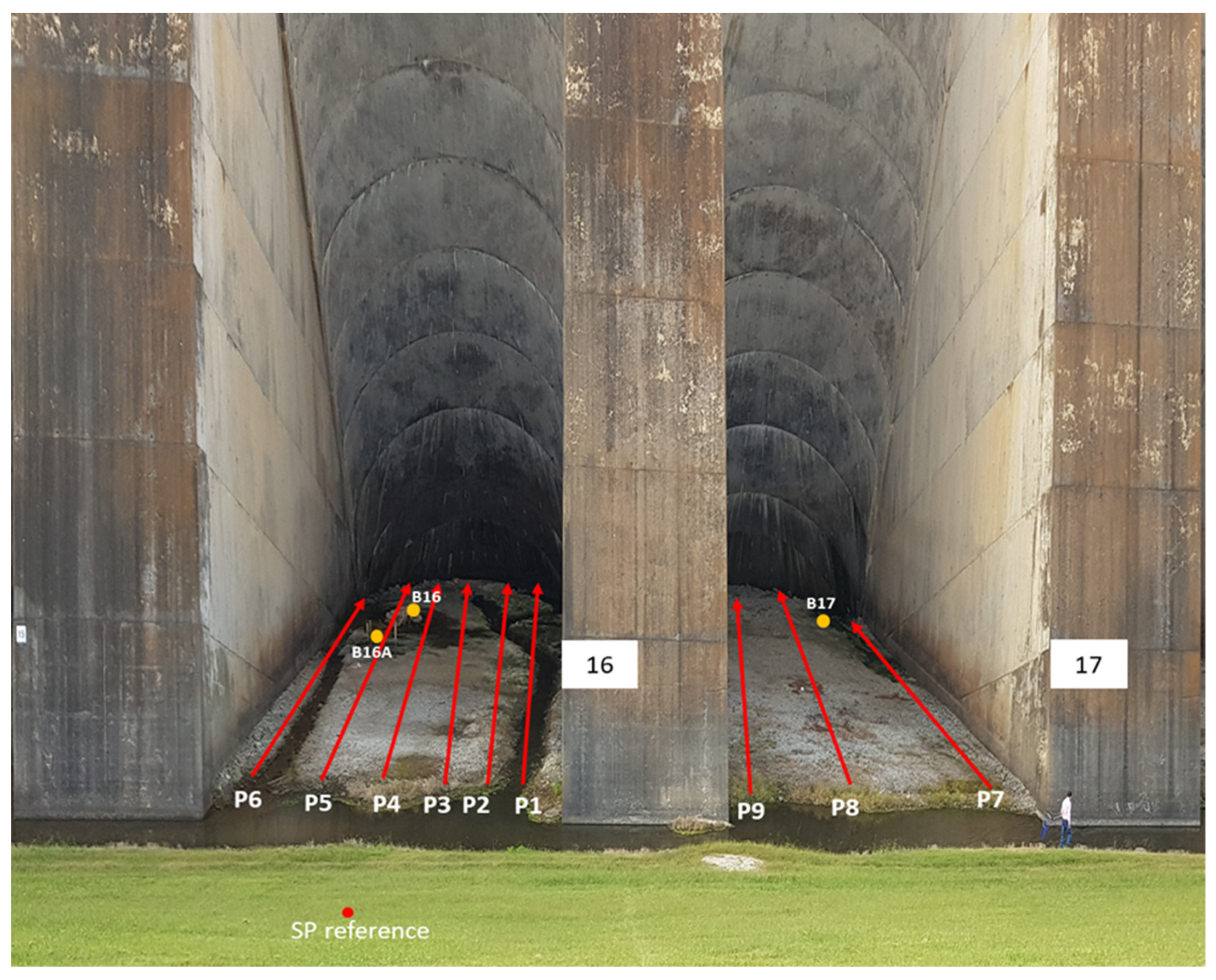
The ERT data were obtained using a Syscal Pro resistivity meter with thirty-six electrodes in a dipole–dipole electrode array configuration, with an electrode spacing of 1.3 m (Table 1). A total of nine ERT profiles were acquired inside the two arches. Six 46 m long ERT profiles (ERT-1 to ERT-6) were acquired inside Arch-16 along P1 to P6 (Figure 6). ERT-1 and ERT-6 were acquired parallel to the buttress about 1 m away from the buttress walls. ERT-2 to ERT-5 were acquired in the central area of the arch at about 3 m distance intervals from each other (Figure 6). Inside Arch-17, three ERT profiles (ERT-7 to ERT-9) were acquired; ERT-7 and ERT-9 were acquired next to the buttress walls, while ERT-8 was acquired at the central part of Arch-17 (Figure 6).
A total of 270 SP stations were measured inside Arch-16, along P1-P6 (Figure 6), using the fixed-based configuration technique with a station spacing of 1 m. This technique involves measuring the electrical potential with respect to a stationary reference point, as explained by [5]. Two non-polarizing Cu/CuSO4 electrodes connected through a long wire (approximately 500 m) and a handheld Fluke 289 true root mean square (RMS) digital multimeter were used for the SP measurements. Before beginning any measurements, two non-polarizing electrodes were buried at the soil surface and placed together to maintain a zero potential between them. One electrode was used as a reference while the other was moved along the profile. The reference electrode was buried along the downstream berm area of the dam, about 60 m away from the first station to avoid spurious readings. The voltage difference between the fixed and the moving electrodes was evaluated before and after conducting SP readings for each profile to compensate for the electrode drift. To ensure the reliability of SP measurements, a shallow hole was dug at each station to mitigate the impact of dry surface and decrease the contact resistance between the ground and electrodes. During the SP measurements, contact resistances were measured using the digital multimeter. The resistances range from 3 kΩ to 65 kΩ, with an average of 12 kΩ across all the survey. This value is significantly lower than the internal impedance of the digital multimeter, which is 100 Mega Ohm.
Six P-wave refraction profiles were collected in Arch-16 along P1 to P6 (Figure 6) to estimate the Vp of the subsurface material. A 10 kg hammer was utilized as the source, and 24 vertical 14 Hz geophones were spaced at 2 m intervals in order to be used as receivers. The record had a length of 1.0 s and a sampling rate of 0.5 ms.

3.2. Data Acquisition from the Downstream Berm

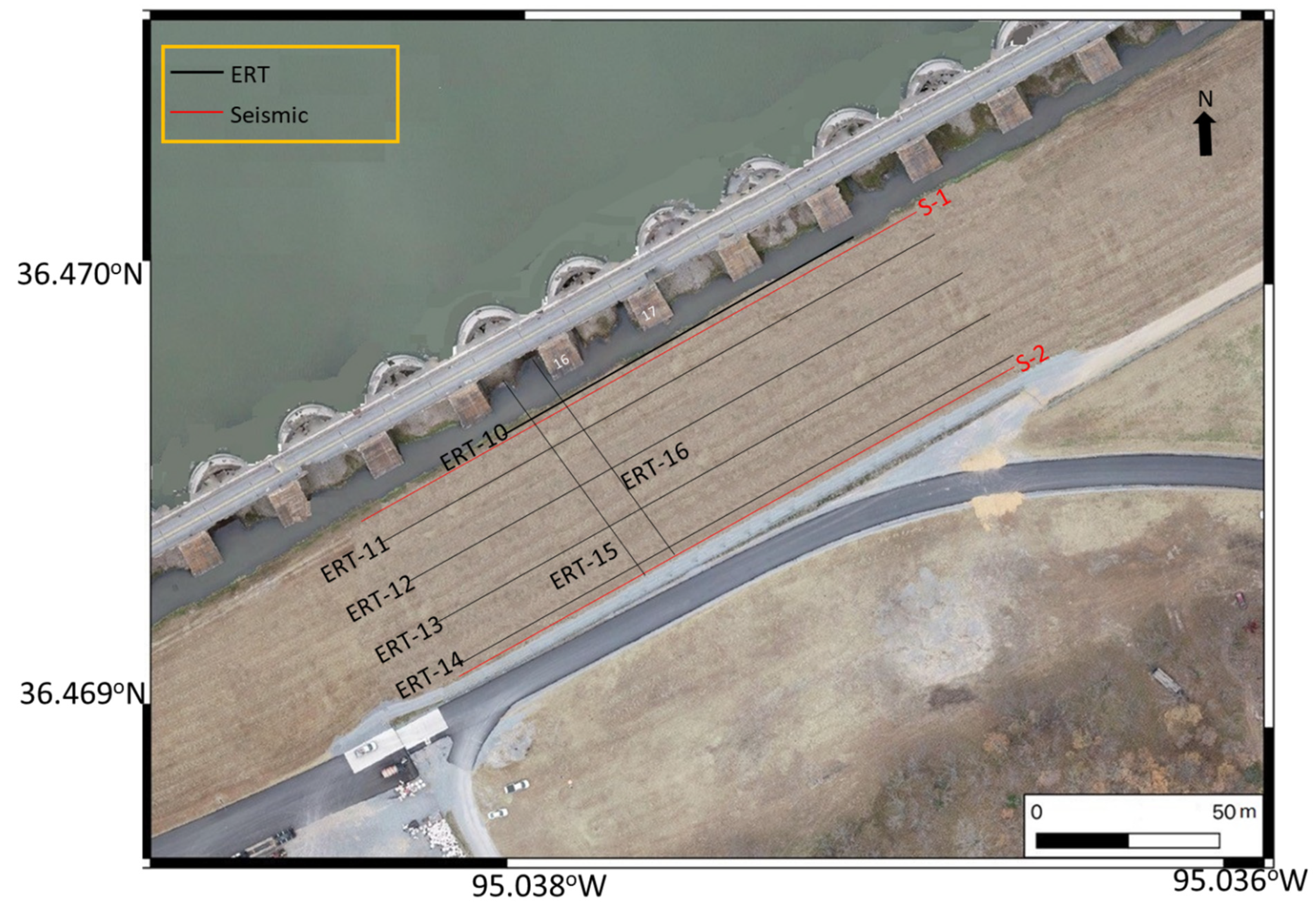
A suite of parallel ERT profiles (ERT-10 to ERT-16) were acquired from the downstream berm of the Pensacola Dam (Figure 7). ERT-10 was acquired along 106 m distance of the gravel road bounding the drainage ditch using the dipole–dipole electrode array with 72 electrodes spaced at 1.5 m intervals to provide optimum vertical and lateral resolution of the shallow foundation rock. ERT-11 to ERT-14 were acquired along the upslope part of the downstream berm using the dipole–dipole electrode array with 54 electrodes and a coarser electrode spacing of 3 m to allow for an imaging foundation rock under the thick-filled materials. We also acquired two southeast-northwest parallel ERT profiles (ERT-15 and ERT-16) with electrode spacing of 1.5 m. The two profiles started from the top of the downstream berm and extended inside Arch-16 (Figure 7).
MASW and S-wave reflection profiles (S1 and S2) were collocated along ERT-10 and ERT-14 (Figure 7). The MASW profile was acquired using a land streamer with 24 vertically polarized 4.5 Hz geophones spaced at 1.5 m interval and a 10 kg sledgehammer as a source, to estimate the Vs of the subsurface. The S-wave reflection data were acquired using a 2 kg sledgehammer horizontally hitting a rolling source. The data were acquired using a land streamer comprising 24 horizontally polarized geophones spaced at 0.75 m interval.

3.3. Data Processing

The raw electrical resistivity data were filtered to eliminate noisy points (data points having extremely high or extremely low apparent resistivity values) using PROSYS II software. The filtered data were exported from PROSYS II software V3.14 into Res2DInv software V3.18 for further processing and inversion [54]. The Res2DInv inversion code utilizes a non-linear optimization procedure to compute the distribution of 2D electrical resistivity in the subsurface [55]. The code subdivides the subsurface into rectangular blocks in order to analyze the resistivity models with a finite difference method [54]. To achieve this, it utilizes a least-squares approach which makes use of a standard least-squares constraint (L2-norm). This technique reduces the discrepancy between the measured and estimated apparent resistivity by minimizing the square of the difference. The standard Gauss–Newton optimization technique was used to solve the least-squares equations, and appropriate optimum inversion parameters such as damping factors, convergence limit, and number of iterations were selected for the inversion. The resistivities of the model blocks were iteratively modified until the measured resistivity values of the model match the real measurement values [54]. The SP data were displayed in the Excel software and anomalous spiking measurements were removed from the data. The filtered data were then gridded in the Golden Surfer software v12 using the kriging technique to generate a 2D contour SP map.
To process and invert the seismic refraction data, we used the time-term and tomography inversion techniques within the SeisImager software [56]. The SeisImager code uses a non-linear least-squares approach for the time-term inversion step and wavefront propagation method to model the travel time [57]. To obtain the velocity model, the inversion process starts with an initial velocity model, developed during the time-term inversion, and then gradually traces rays through the model to decrease the root mean square (RMS) difference between the calculated and observed travel times. The wavefront propagation method calculates travel times by estimating the time required for the wave to propagate from the source to each adjacent node. In this approach, the node with the shortest travel times path leading to it was used as the source, and this process is repeated until the entire model is traced to obtain the 2D seismic P-wave refraction profile [58].
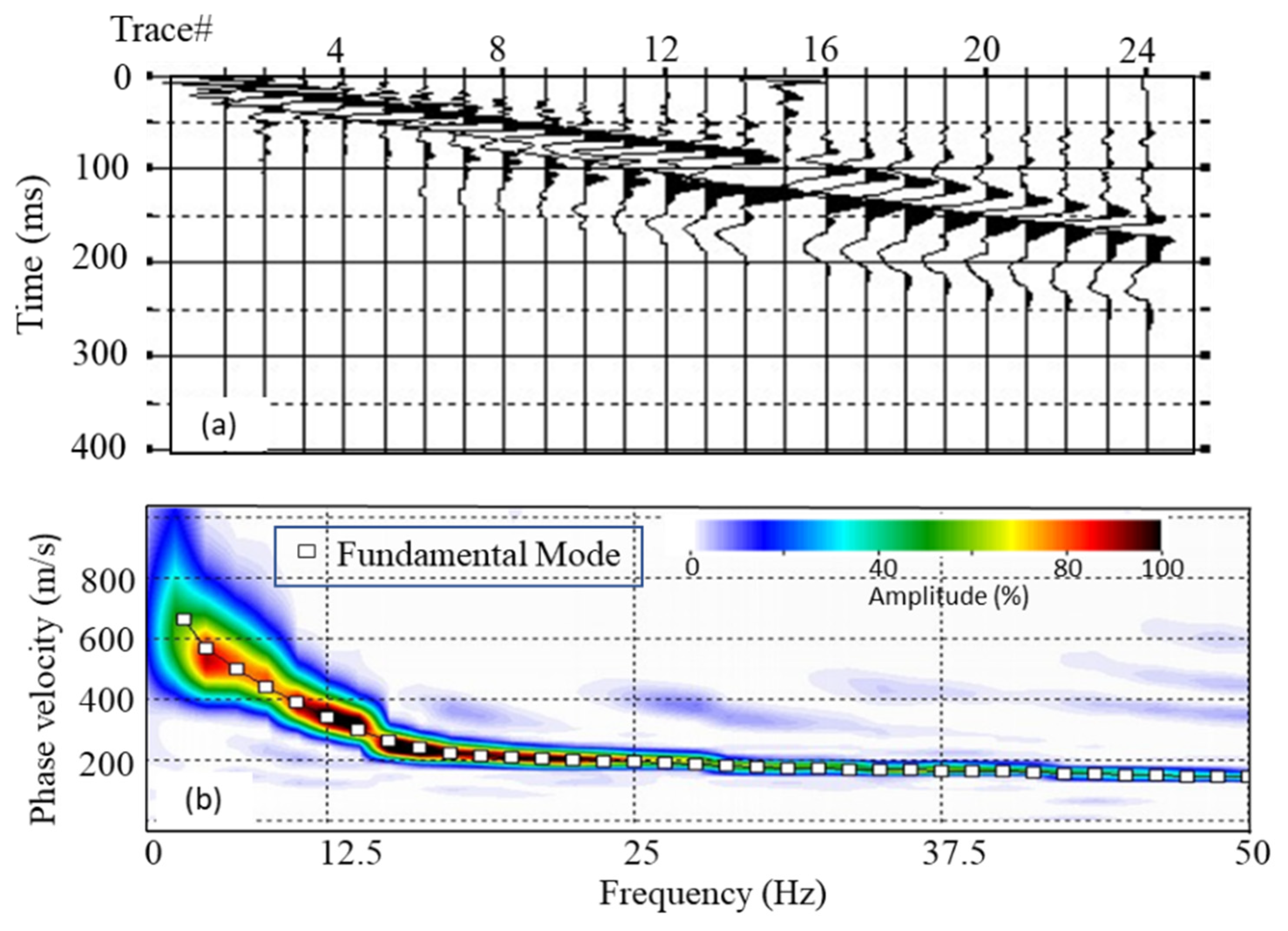
We processed the MASW data using the SurfSeis 6 software [59]. The general steps to obtain the 2D Vs pseudosection from the analysis of the Rayleigh wave using the MASW technique include: (1) identification of the Rayleigh wave from shot gathers; (2) creation of dispersion curves and determination of the curves from each record; (3) inversion of the dispersion curve independently to attain a 1D Vs variation with depth from each record; (4) interpolation of the 1D Vs profiles in a successive manner using the receiver station to obtain a 2D Vs pseudosection. The inversion method is an iterative method which relies on the least-squares technique [38], where an initial earth model (Vs, Vp, density, and layer thickness) is defined at the beginning of the iterative inversion process. Figure 8 shows an example of shot gather and the obtained phase velocity-frequency (f-c) spectrum to demonstrate the evaluation of the quality of results.
The S-wave reflection data were processed using the ProMax seismic software. The field geometry was assigned to the data file header and followed by applying a trapezoid Ormsby bandpass filter to eliminate the unwanted high and low frequency noise. The trace amplitude was balanced using an automatic gain control (AGC) with 150 ms window. Surface wave noise attenuation (SWNA) module was applied to remove surface wave arrivals, since, most often, the surface wave masks the S-wave reflection signal. Moreover, we applied predictive deconvolution to remove multiples and improve the temporal resolution. Normal moveout (NMO) stretch mute was used to remove the refraction and preserve the reflection arrivals [60]. The data were sorted into a common midpoint (CMP) domain and stacked to obtain the final stacked section. A frequency space Fx-deconvolution filter of Wiener Levinson type was applied post processing to the final stacked data to eliminate the random noise and strengthen the lateral coherency of the signal [61]. Finally, the stacked time profiles were converted from time to depth using smoothed stacking velocity fields. The depth profiles were stretched and squeezed to match the depth information from the available boreholes. Subsequently, the depth profiles were exported in SEG-Y format for interpretation.

4. Hydrogeochemical Investigation

We collected a total of eight water samples (two duplicate samples each from Surface Lake water, benthic Grand Lake water, and the water flowing from the artesian well in Arch-16, and Arch-16 spigot water (water sample from a pipe that is inserted into the ground at Arch-16, intended to be a groundwater source). On site, the water samples were filtered and maintained by forcing 60 mL of water through a 25 mm disposable filter with a mixed-cellulose-ester membrane that has 0.45 μm as the pore size using a syringe. We transferred the water samples into plastic bottles and maintained them in ice. The samples collected were transferred to the GRDA Pensacola Dam laboratory in Langley for analysis on the same day we collected them. The geochemical analysis of the samples included measuring the temperature, pH, electrical conductivity (EC), total dissolved solids (TDS), total hardness, total alkalinity, orthophosphorus, dissolved oxygen, nitrate, bicarbonate, and major cations and anions.
The initial step in the laboratory was filtering the water samples using Fisher P-4 paper filters, and the analysis was carried out on the filtrates. The EC, temperature, TDS, pH, and dissolved oxygen were measured using direct electrode reading of filtered water. The hardness was expressed as part per million (ppm) of CaCO3 [62]. Ions such as sodium (Na), potassium (K), calcium (Ca), magnesium (Mg), iron (Fe), and manganese (Mn) were obtained by direct reading on inductively coupled plasma (ICP) spectrometer [63]. The total alkalinity (as HCO3) was obtained by titration with 0.02 N H2SO4 from pH 8.3 to 4.5, while automated cadmium reduction was used to estimate NO3-N [62].

5. Data Interpretations

5.1. Data Acquired Inside the Arches

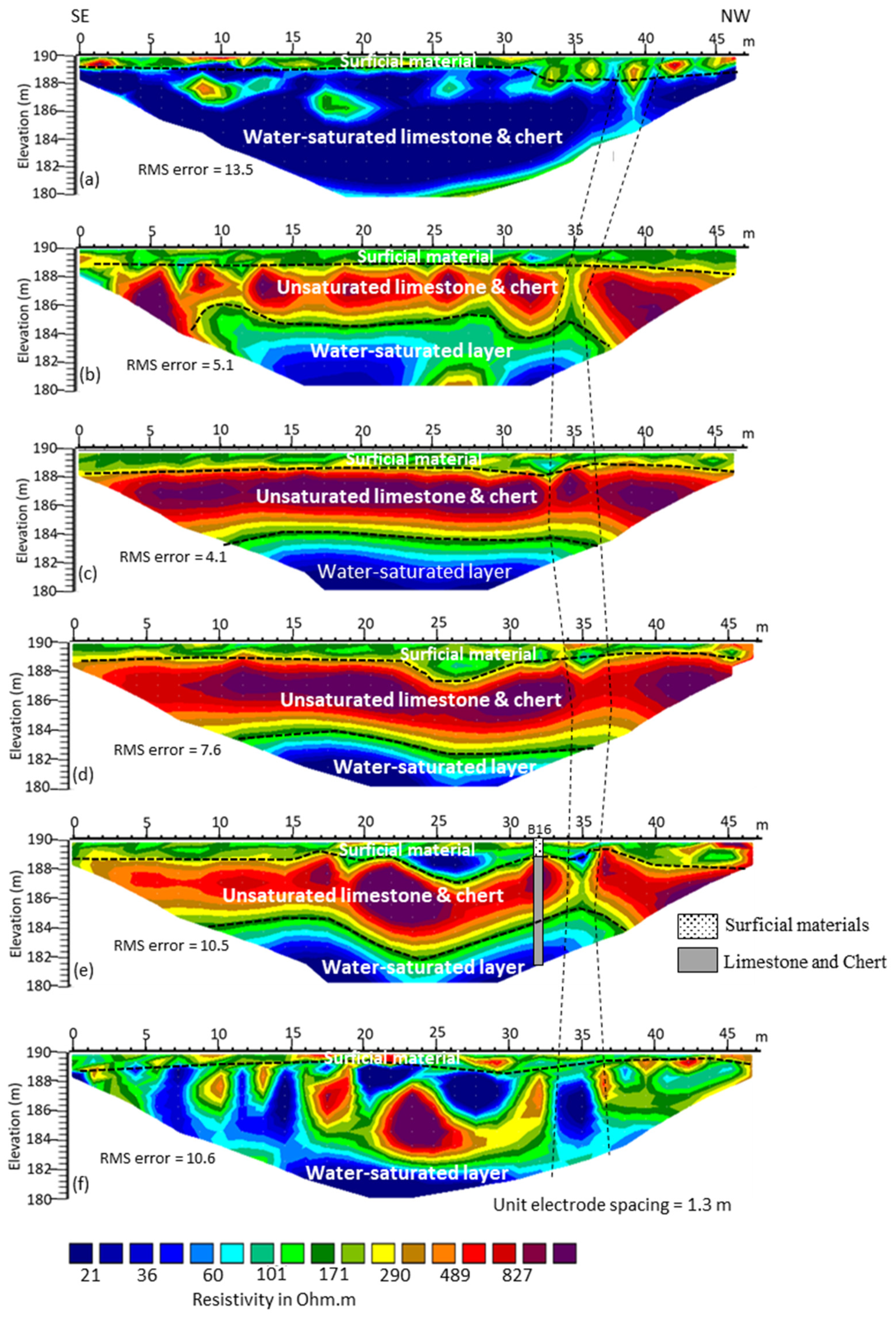
All the ERT profiles (ERT-1 to ERT-9) imaged the subsurface to a total depth of 10 m (Figure 9). Over the span of Arch-16, the ERT profiles delineated an upper layer of an average thickness of 2 m and variable resistivity values ranging from 20 to >800 Ωm, interpreted as the surficial materials layer. The resistivity of the surficial materials (mainly clay, silt, sand, and gravel) is relatively much lower next to the buttress walls (ERT-1 and ERT-6) than at the central part of the arch, most likely due to surface water seepage observed near the buttress walls. Next to the buttress walls and along ERT-1 and ERT-6, the interpreted surficial materials layer is underlain by a layer of significantly low resistivity <20 Ωm, appearing at a ground elevation of ~189 m, interpreted as the water-saturated foundation rock (limestone and chert). The high-water saturation within the foundation rock near the buttress walls may be due to previous rock excavation and blasting at these locations.
Away from the buttress walls, the surficial materials overlie a 4 m thick layer of relatively high resistivity (290 to >800 Ωm) interpreted as an unsaturated limestone and chert layer. Below this layer, at a ground elevation of ~184 m above mean sea level (amsl), the resistivity drops abruptly below 100 Ωm. This sudden drop in resistivity is most likely because the unsaturated limestone and chert became fractured and water-saturated below an elevation of ~184 m amsl. A narrow zone of relatively low resistivity was observed along the six ERT profiles marked by dashed lines between distance marks 33 and 36 m in Figure 9, that may be attributed to a water-saturated vertical jointing or fractured zone. The interpreted fractures may act as a vertical conduit that allows for vertical artesian flow from the underlying water-saturated zone.
The SP profiles were plotted on the top of the ERT profiles in Arch-16 (Figure 9). The positive SP anomalies observed on profiles near the buttress walls complement the ERT profiles, suggesting that the anomalous seepage beneath Arch-16 is primarily flowing vertically, moving upward towards the surface. When examining the SP values beneath Arch-16, a consistent pattern is observed. The SP readings align with the ERT profiles, showing that the profiles situated at the central area of the Arch generally exhibit low SP values, while the SP gradually increases towards the buttress walls.
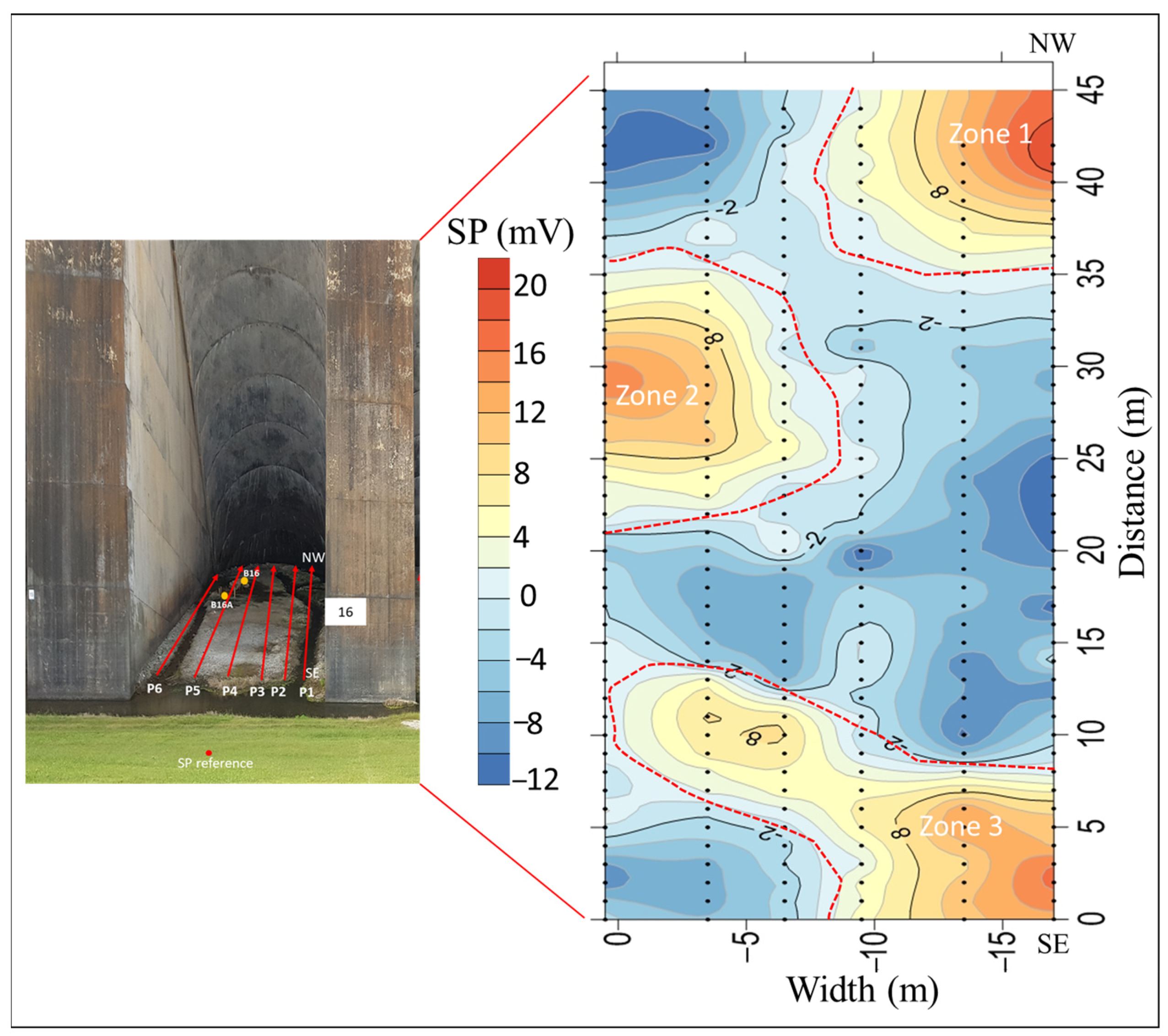
The SP profiles were then gridded and contoured to generate a 2D SP map for the area inside Arch-16 as shown in Figure 10. The SP contour map shows the presence of anomalous self-potential in three zones (marked by green broken lines). The areas along and around these three zones (Zones 1 to Zone 3) are interpreted as potential seepage pathways. The seepage seems to be moving along the buttress walls towards the center of the arch. The delineated seepage pathways seem to be associated with a single vertical fracture or a cluster of fractures. The presence of high positive SP anomalies further suggests the possibility of vertical or sub-vertical groundwater flow towards the surface under the arch [64], as supported by the ERT data. However, it is important to note that further information and analysis, including hydraulic gradients, groundwater levels, and hydrogeological conditions, are necessary to confirm this interpretation.
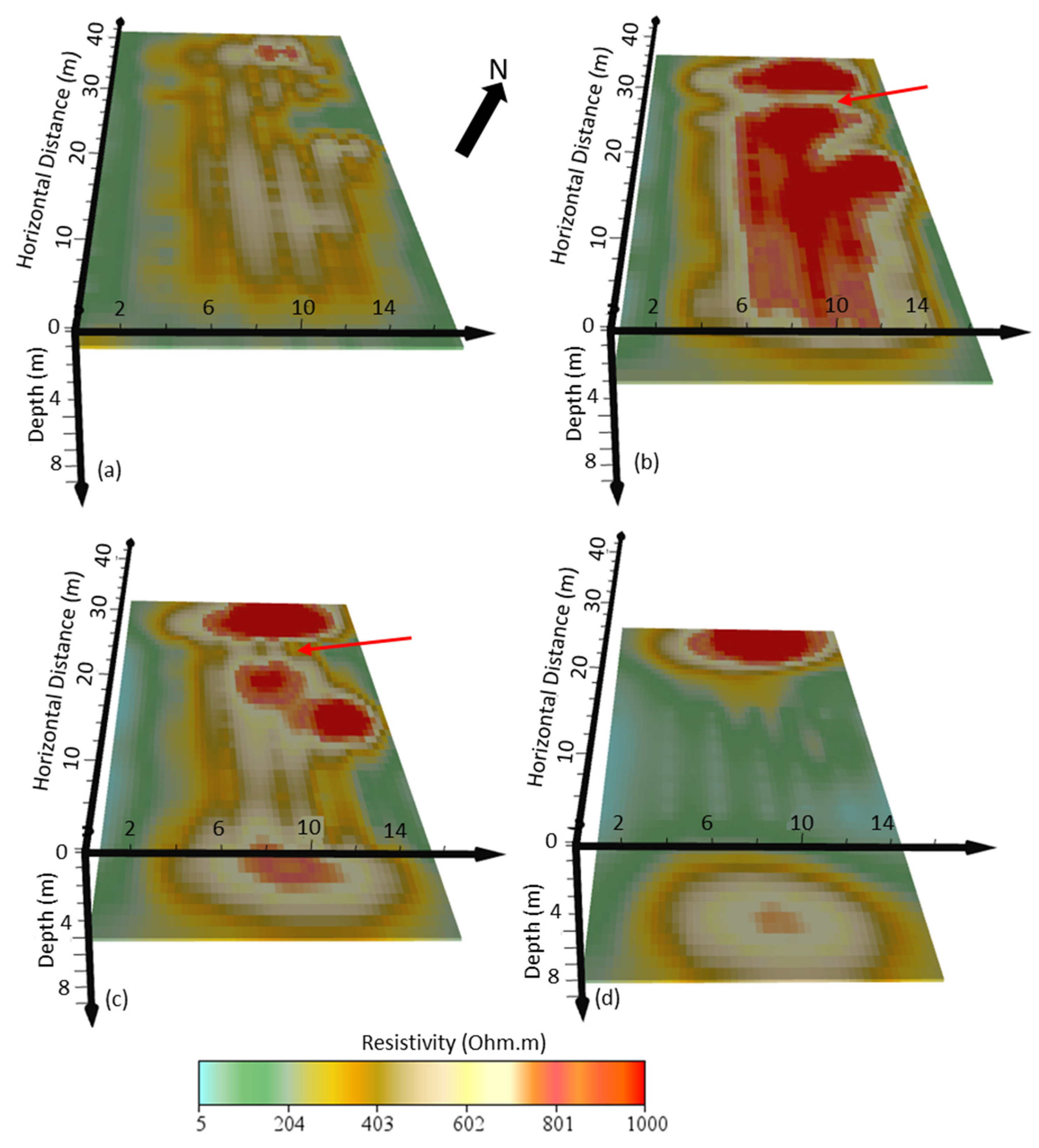
The interpreted fractured zone inside Arch-16 in Figure 9 is better identified along the resistivity depth slices of the 3D resistivity volume generated from interpolating the six ERT profiles (Figure 11a–d). A linear east-west low resistivity feature cuts across the 3 m and 5 m depth slices, indicating the location of the previously interpreted vertical fractures within this layer at this specific location (indicated by the red arrow in Figure 11). The depth slice of 1 m represents the surficial materials (Figure 11a), while slices at 3 and 5 m depths represent the unsaturated limestone and chert rock, respectively (Figure 11b,c). The resistivity depth slice of 8 m shows the water-saturated limestone and chert layer (Figure 11d).
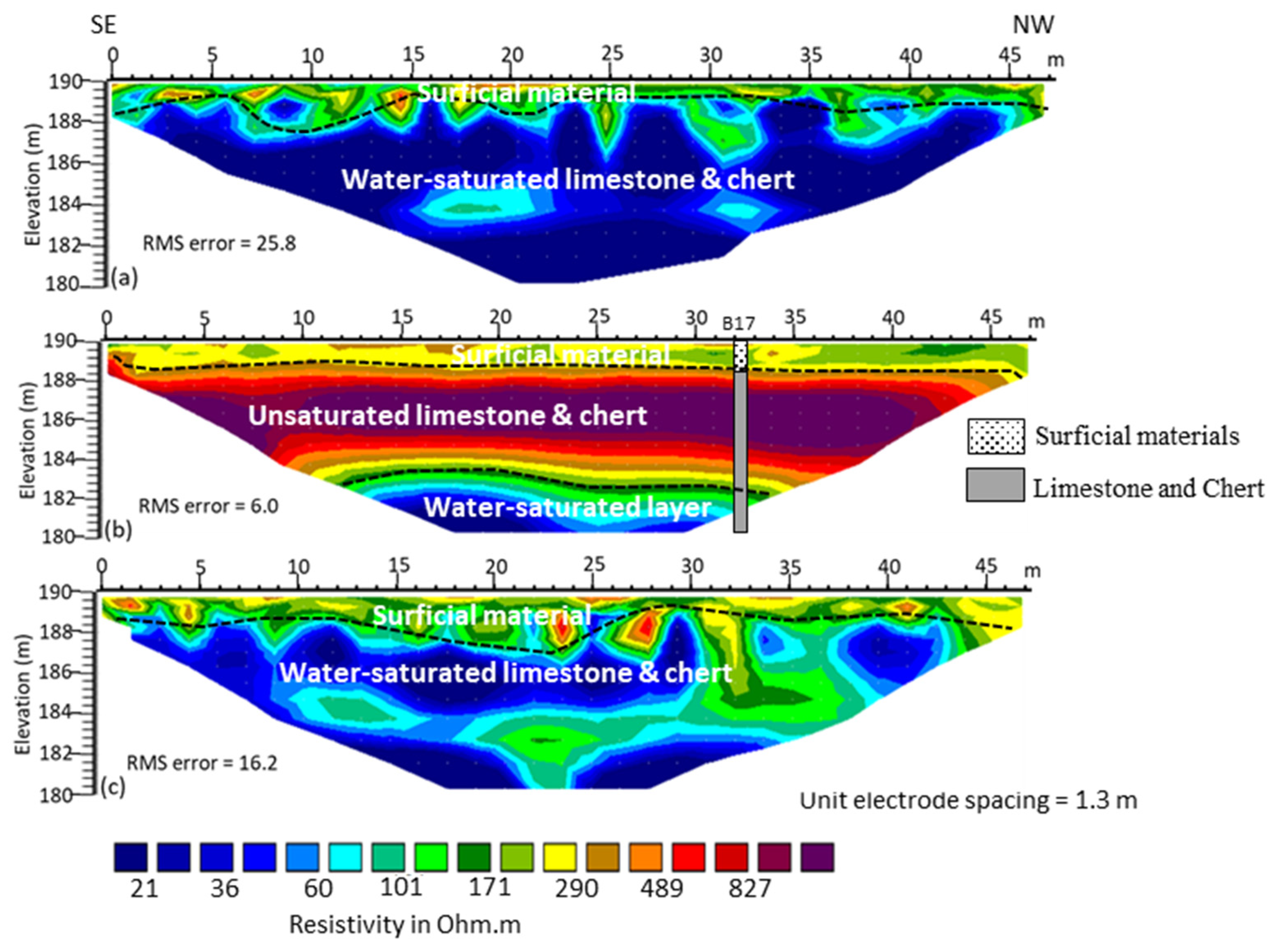
The three ERT profiles from Arch-17 (Figure 12) showed a similar subsurface model as imaged by the ERT profiles in Arch-16. Both ERT-7 and ERT-9 (Figure 12a,c) delineated the interpreted surficial materials layer and the interpreted foundation rock (water-saturated limestone and chert). ERT-8 (Figure 12b) delineated the surficial materials (mainly clay, silt, sand, and gravel), unsaturated limestone and chert layer, and the water-saturated foundation rock.
The high root mean square (rms) error observed in ERT-1, ERT-6, ERT-7, and ERT-9 (acquired next to the buttress walls) may be due to the 3D nature of the underlying structures along these profiles. The 2D ERT often assumes that the electrical resistivity of the subsurface materials remains uniform in the vertical direction along the measurement line. However, when the subsurface deviates from this assumption, the 2D ERT results can be prone to errors [65,66,67,68]. Where geological structures outside the 2D resistivity profile are projected onto the 2D profile, it causes what is called the “3D effect” that may lead to inaccuracies in the results. Detected seepages may have also influenced the 2D electrical resistivity measurements.
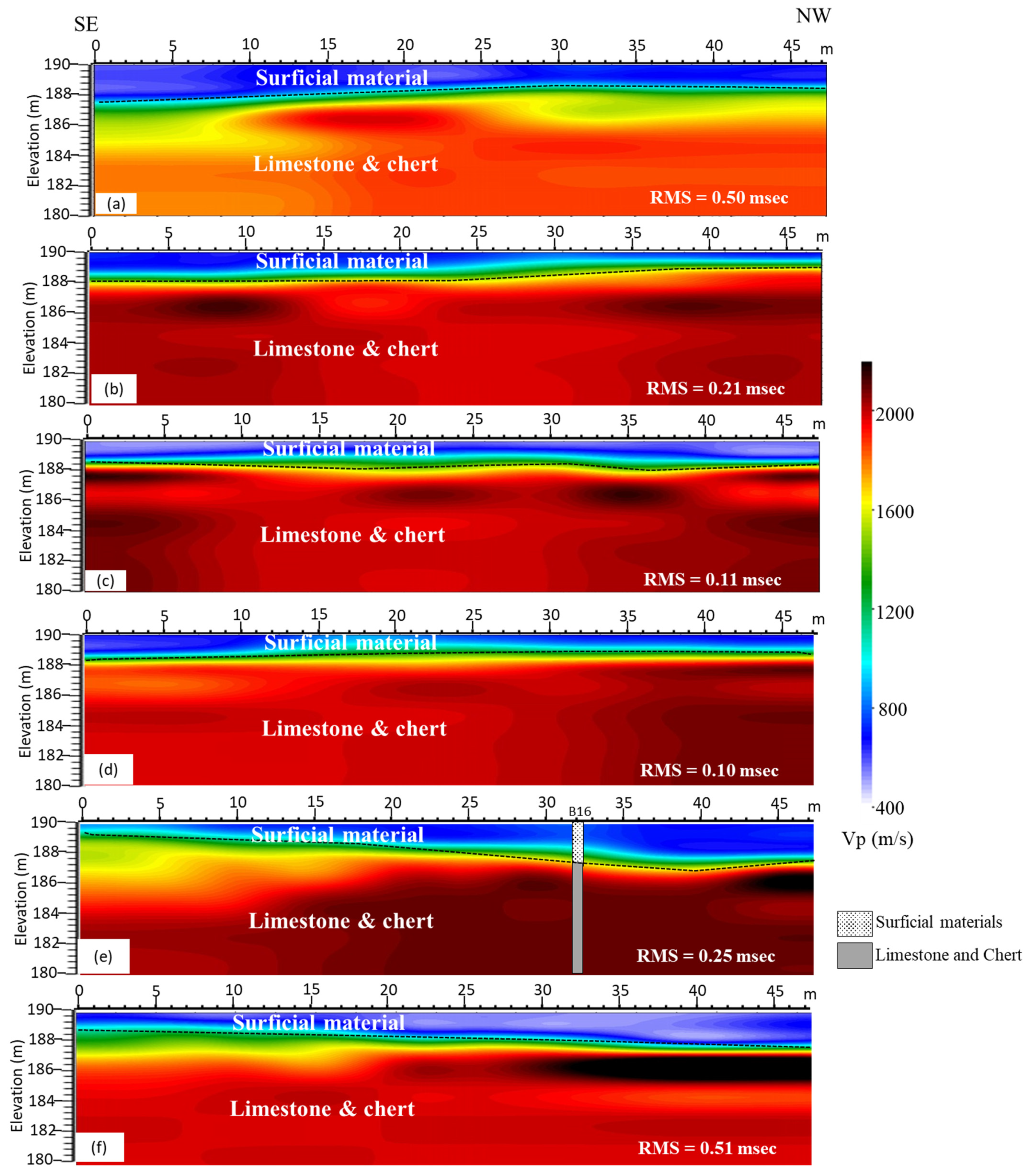
Figure 13a–f displays the six seismic refraction profiles acquired from Arch-16. These profiles characterized the subsurface into an upper low velocity layer (<500 m/s) with an average thickness of 2 m corresponding to the interpreted surficial materials. A relatively high Vp (1200 to 2400 m/s) layer appears at an average ground elevation of 188 m and extends to the bottom of the profiles, interpreted as the dam foundation rock (limestone and chert). The Vp of the dam foundation rock along seismic refraction profile 1 (Figure 13) is relatively low compared to the other five seismic refraction profiles, which may indicate that the dam foundation rock has been fractured near the buttress wall.

5.2. Data Acquired from the Downstream Berm

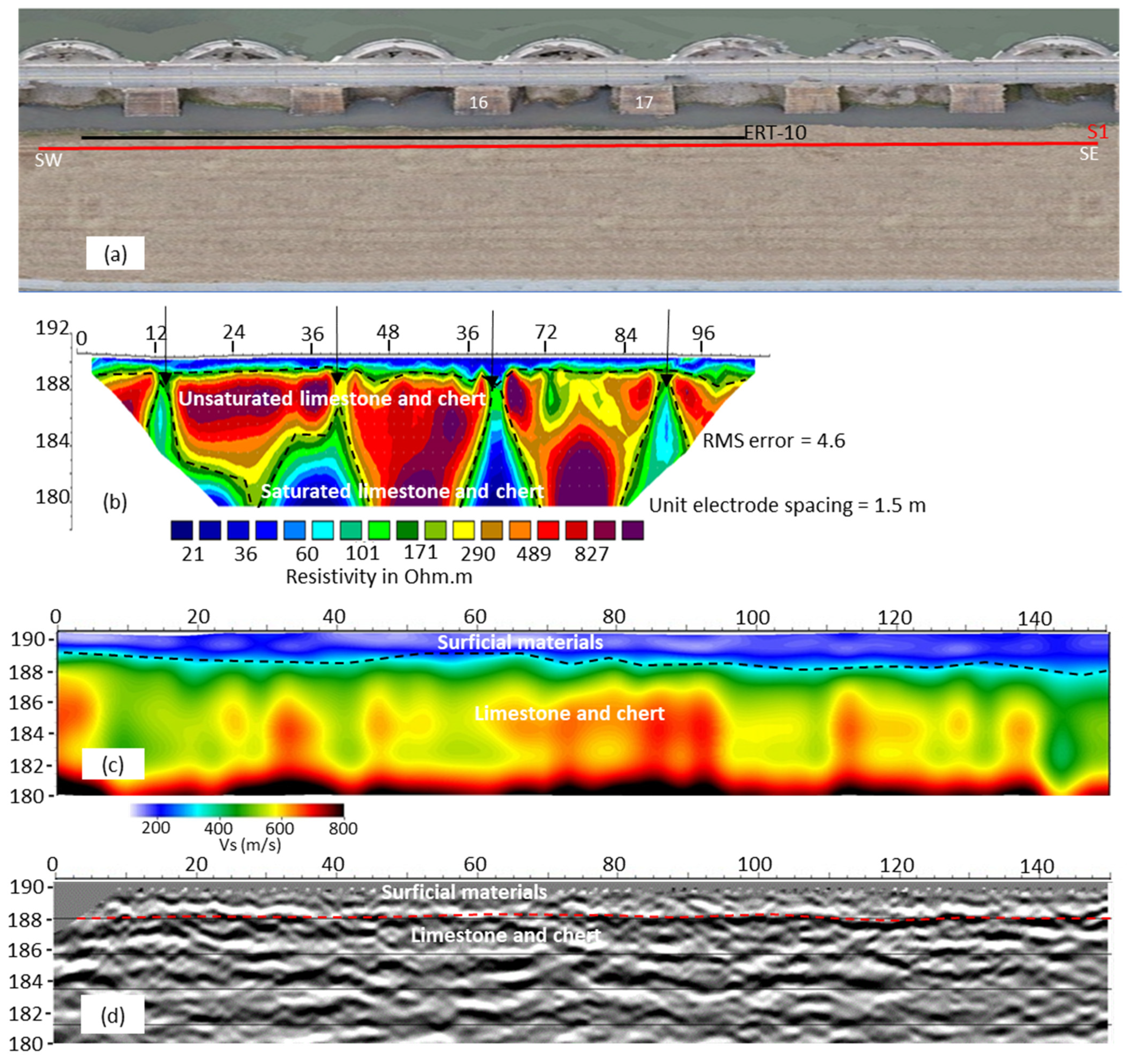
The open area along the downstream berm provided more room for acquiring relatively longer geophysical profiles and hence, imaging greater depths. ERT-10 was acquired along the gravel road parallel to the axis of the dam (Figure 14a) and at the same ground elevation as the area inside the arches. This profile was acquired with relatively narrow electrode spacing to provide higher resolution for comparison with the ERT profiles inside the arches. ERT-10 characterized an upper layer with a relatively low resistivity (<60 Ωm) and an average thickness of 2 m corresponding to the upper surficial materials identified inside the arches. The second geoelectric layer appears at an elevation of 188 m with resistivity values between 290 and 1070 Ωm and an average thickness of 8 m, interpreted as the unsaturated limestone and chert imaged below the arches. Observed lateral resistivity variations within this layer are most likely caused by the changes in water content within this unit caused by changes in the degree of jointing, discontinuities, and weathering.
The narrow and nearly vertical low resistivity zones indicated by black arrows along ERT 10 are interpreted as fracture zones. These fracture zones appeared to correspond to the location of the buttress of the arches (Figure 14b). The shape, size, and distribution of the vertical low resistivity zones (relative to the buttress location) suggest that these anomalies may be highly fractured limestone zones from previous rock blasting during the construction of buttress foundations. The third geoelectric layer contains a series of large, low resistivity anomalies towards the bottom of the layer interpreted as water-saturated zones of the limestone and chert foundation rock.
MASW Vs profile 1 (Figure 14c) also shows two seismic velocity layers. An upper surficial materials layer with Vs ranges between 150 and 400 m/s and an average thickness of 2 m. The bottom seismic Vs layer appears at elevation 188 m, which matches the ERT profile. This layer has a Vs > 600 m/s that corresponds to the dam foundation rock (Figure 14c). The Vs within the dam foundation rock exhibits significant lateral variability similar to the ERT profile. Vs is not affected by water saturation, and therefore the lateral Vs variation is mainly attributed to lateral changes in the rock strength due to the spatial variability of the limestone and chert, and possibly the degree of the fracturing, discontinuities, and weathering.
Seismic S-wave reflection profile 1 shows a continuous strong seismic reflector marking the top of the dam foundation rock beneath the layer of unconsolidated materials (Figure 14d). Below this layer, the seismic reflector seems to be less coherent with evident anomalous amplitudes and diffractions, which indicate a high degree of heterogeneity within the dam foundation rock layer (Figure 14d). The seismic data of this profile are of relatively low quality due to the poor coupling between the streamer sleds and the gravel road, in addition to the effect of the traffic noise.
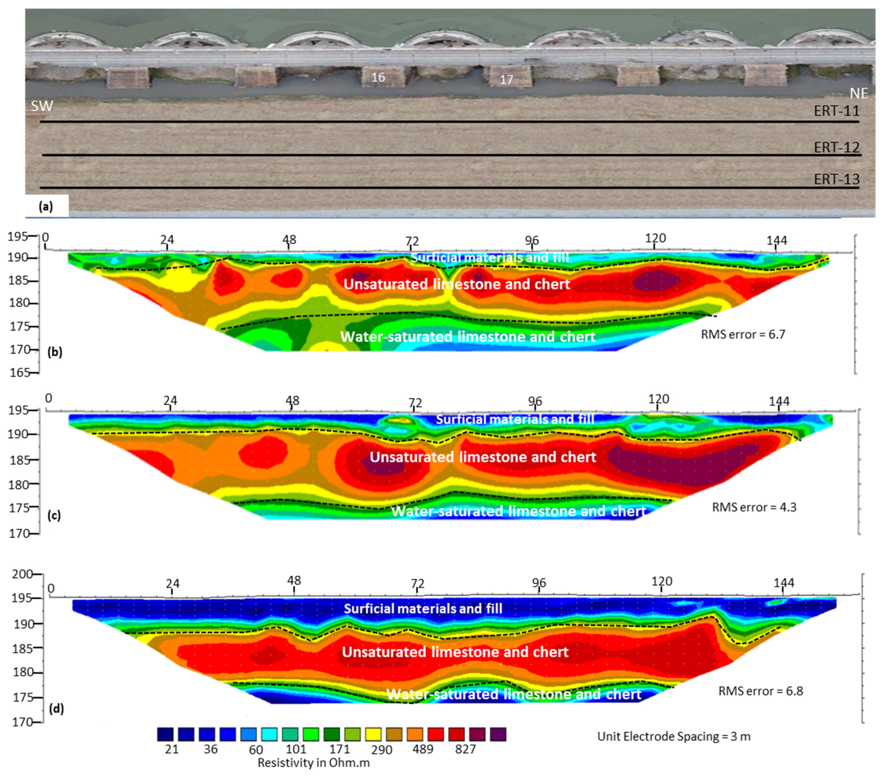
To track the interpreted fracture zones inside the arches and investigate the integrity of the dam foundation rock at the downstream berm, we interpreted the acquired ERT profiles along the slope of the downstream berm. Figure 15 shows the ERT profiles acquired along the downstream berm. The three resistivity profiles (ERT-11 to ERT-13) imaged the subsurface to an average depth of 25 m showing three geoelectric layers (Figure 15). The upper geoelectric layer has low resistivity values (<150 Ωm) occurring from ground surface down to an average elevation of 190 m amsl, interpreted as the berm fill on the top of the dam foundation rock. The thickness of this layer increases from 2 m along ERT-11 to about 6 m along ERT-13 (Figure 15). The second geoelectric layer shows relatively high resistivity (290 to 1070 Ωm) with some degree of lateral resistivity variation. This geoelectric layer appears at almost the same elevation (190 m amsl) along the three resistivity profiles with a thickness ranging between 12 and 15 m and is interpreted as an unsaturated limestone and chert layer which may have lower water content.
The third geoelectric layer, identified by a significant drop in resistivity with depth (<60 Ωm), appears at an average elevation of ~175 m amsl, and is interpreted as the water-saturated foundation rock (limestone and chert). The bottom of the unsaturated rock layer with its transition to the higher hydraulically water-saturated limestone and chert layer in the downstream berm seems to occur around 8 m deeper than the bottom of the same layer below the arches.
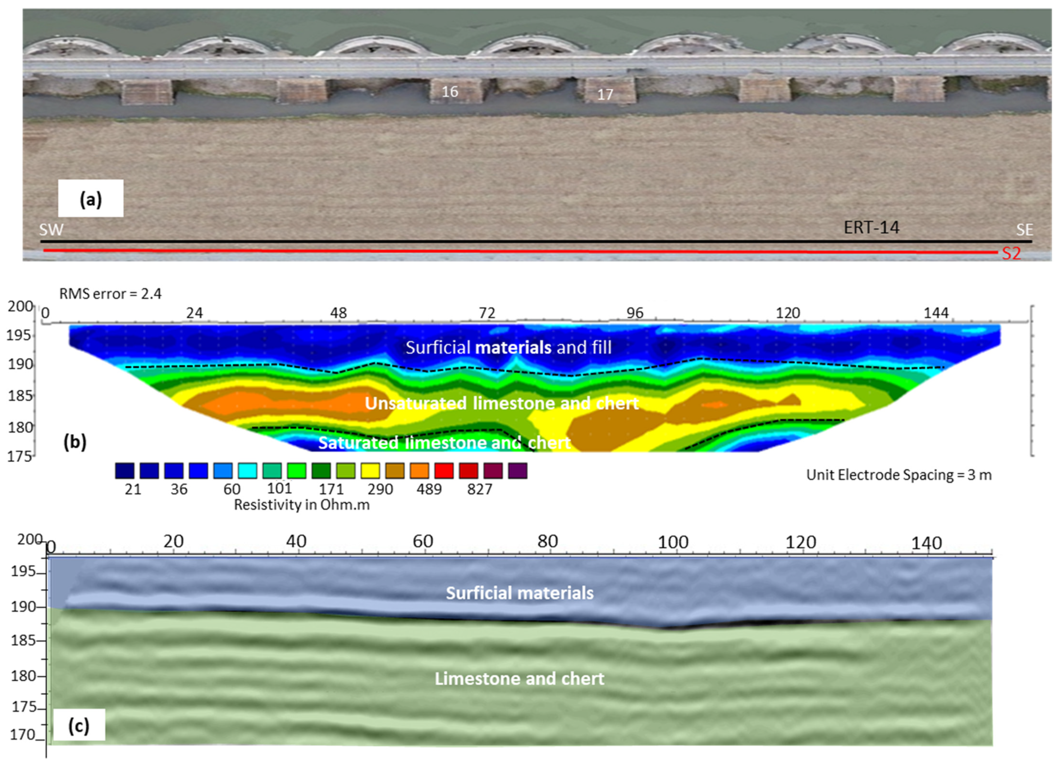
The acquired ERT and S-wave seismic reflection at the top of the slope in the downstream berm is shown in Figure 16. The resistivity profile (ERT-14) showed a similar subsurface model as the resistivity profiles acquired along the slope in the downstream berm. The ERT-14 profile (Figure 16b) delineated the surficial materials and the berm fill (resistivity < 150 Ωm), unsaturated limestone and chert layer (resistivity 290 to 1070 Ωm), and the water-saturated foundation rock (resistivity < 60 Ωm).
The thickness of the surficial material and berm fill layer along ERT-14 is about 8 m (Figure 16b). The unsaturated limestone and chert layer along ERT-14 also appears at an elevation of 190 m amsl similar to the same layer along the resistivity profiles ERT-11 to ERT-13. The lateral variability in resistivity within the unsaturated limestone and chert layer along this profile may be due to variation in the spatial variability of the limestone and chert and/or in the degree of fracturing, discontinuities, and weathering. The water-saturated limestone and chert appears at a similar elevation as imaged along the slope of the downstream berm.
The S-wave reflection profile 2 acquired at the top of the berm delineated two subsurface models including the surficial materials and berm fill, and the foundation rock (Figure 16c). The top of the unsaturated limestone and chert layer was marked by a continuous strong seismic reflector at an elevation of 190 m amsl.
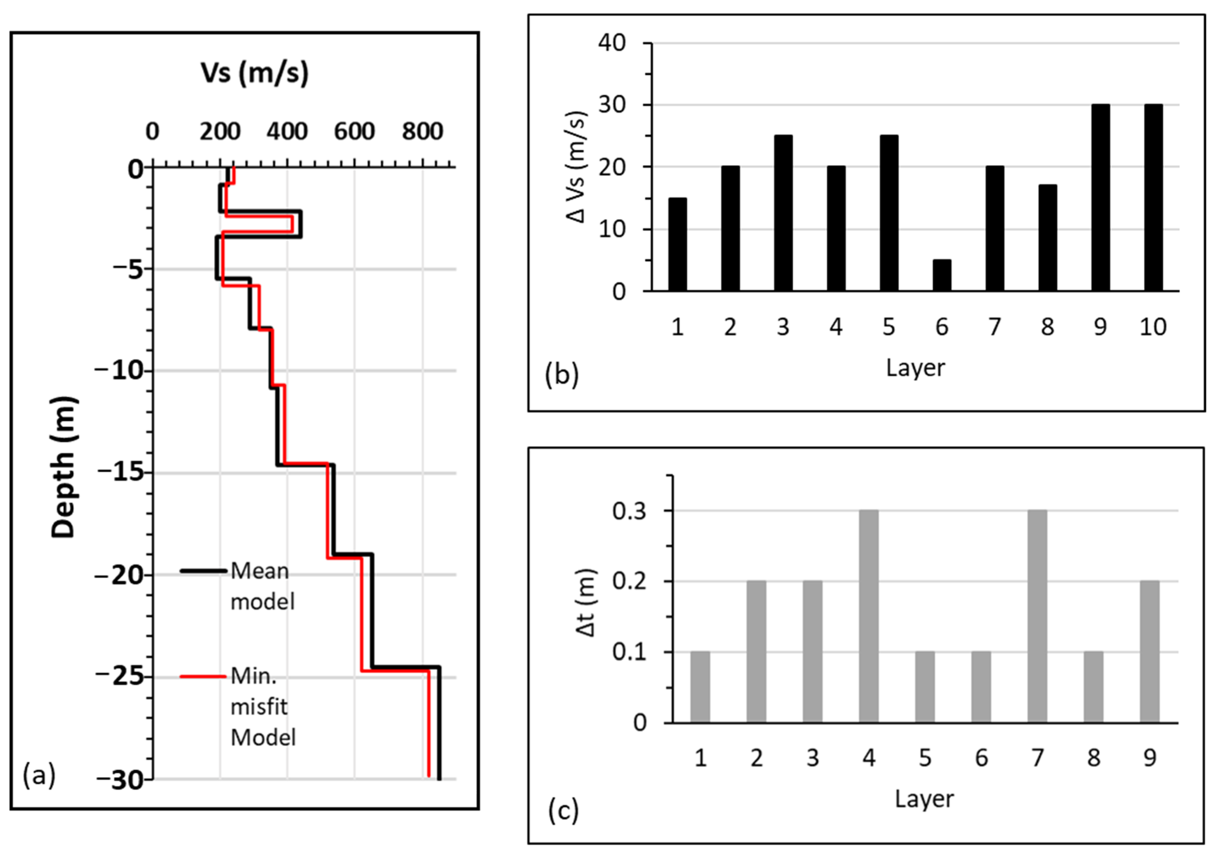
The mean and the minimum misfit models of the 1D MASW generally show an increase in Vs with depth (Figure 17a). The minimum misfit model corresponds to the Vs profile that is linked to the global minimum of the misfit function. On the other hand, the mean model is calculated by taking the average of all the accepted models during the inversion process. The slight increase in Vs between 2 and 3.5 m depth in these models indicate the presence of dry materials within the downstream berm at this location of the profile. We also estimated the uncertainties associated with the inverted Vs and that of the layer thickness (Figure 17b,c). The Vs uncertainty (ΔVs) ranges from 5 to 30 m/s, while the uncertainty for the layer thicknesses (Δt) is between 0.1 and 0.3 m.
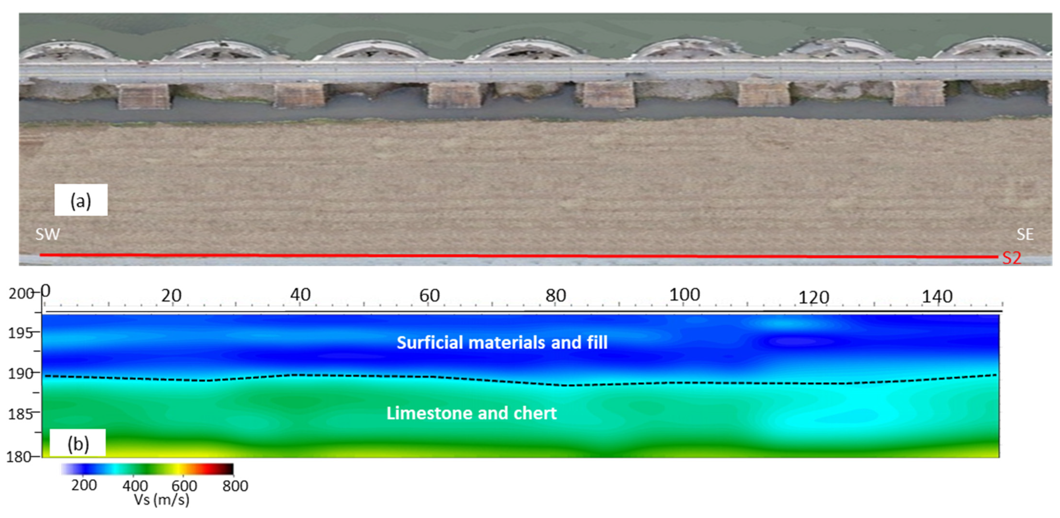
We then interpolated 1D MASW Vs profiles to obtain the 2D Vs pseudosection (Figure 18). The MASW profile 2 displays two seismic velocity layers with Vs ranging from 150 to 600 m/s. The upper layer with Vs ranging from 150 to 300 m/s and an average thickness of 8 m corresponds to the interpreted surficial materials and fill (Figure 18). The bottom seismic Vs layer appears at an elevation of 190 m as delineated by both the ERT and S-wave reflection profiles in the downstream berm. The Vs of this layer ranges between 400 and 600 m/s and corresponds to the dam foundation rock (limestone and chert). The low Vs of the dam foundation rock along this profile may be due to the high degree of fracturing and weathering of the foundation rock. The MASW profile 2 did not image the saturated limestone and chert layer compared to the ERT and S-wave reflection due to the limited penetration depth of the surface wave.
The ERT-15 and ERT-16 profiles were acquired perpendicular to the dam axis, to connect the subsurface models beneath the arches and at the downstream berm (Figure 19). ERT-15 was acquired from the downstream berm to the central part of Arch-16, while ERT-16 was acquired from the downstream berm to the area close to the buttress wall in Arch-16 (Figure 20a). Both ERT-15 and ERT-16 profiles showed comparable subsurface models as the profiles acquired inside the arches and in the downstream berm. The ERT profiles delineated the surficial materials/berm fill and the unsaturated limestone and chert layers in the downstream berm, and showed the surficial materials, unsaturated limestone chert, and the water-saturated foundation rock towards Arch-16.
The thickness of the interpreted surficial materials and berm fill on both ERT profiles increased gradually from an average of 2 m beneath the arches to a maximum of 8 m thick below the downstream berm. ERT-15 shows that the unsaturated limestone and chert increased in thickness from Arch-16 towards the downstream berm (Figure 19). ERT-16, however, only shows the water-saturated foundation rock underlying the surficial materials and berm fill. In addition, both profiles showed that the water-saturated foundation rock appeared at a much shallower depth beneath the arch compared to the downstream berm. We extrapolated the lines representing the top of the water-saturated limestone and chert layer in Figure 19 based on the interpretation of the crossing ERT profiles 11–14 in Figure 15b–d and Figure 16b. The top of the water-saturated limestone and chert layer drops significantly past the base of the dam and declines slightly in the downstream direction. The higher elevation of the water-saturated zone beneath the arches may be due to the uplift pressure beneath the dam base.

5.3. Geochemical Analysis

Table 2 shows the averaged results of the two samples collected from Arch-16 wells, Grand Lake surface, and Grand Lake benthic water. The table also includes the result of the Arch-16 spigot water collected as a groundwater source in Arch-16. The geochemical characteristics of the water from Arch-16 wells and Arch-16 spigot showed similar characteristics. The results of the geochemical analysis of water samples obtained from the Grand Lake were compared to those from Arch-16 wells at Pensacola Dam to help understand the difference between the lake water and Arch-16 well (Table 2). The results show that the Grand Lake surface and Grand Lake benthic water exhibit similar characteristics (Table 2). However, the lake water is significantly different from the water from Arch-16 wells (Figure 20). For example, the concentrations of calcium ions, bicarbonate, TA, TH, TDS, and EC in the water from Arch-16 wells are much higher than the lake water (Figure 20). On the other hand, parameters such as nitrate, K+, pH, and dissolved oxygen have higher concentrations in lake water compared to the Arch-16 well (Figure 20). The lake water has a higher concentration of dissolved oxygen than the Arch-16 well. The concentration of dissolved oxygen is 8.48 mg/L for lake surface and 8.92 mg/L for lake benthic, while the concentration of dissolved oxygen in the Arch-16 well is down to 2.64 mg/L (Table 2; Figure 20).

6. Discussion

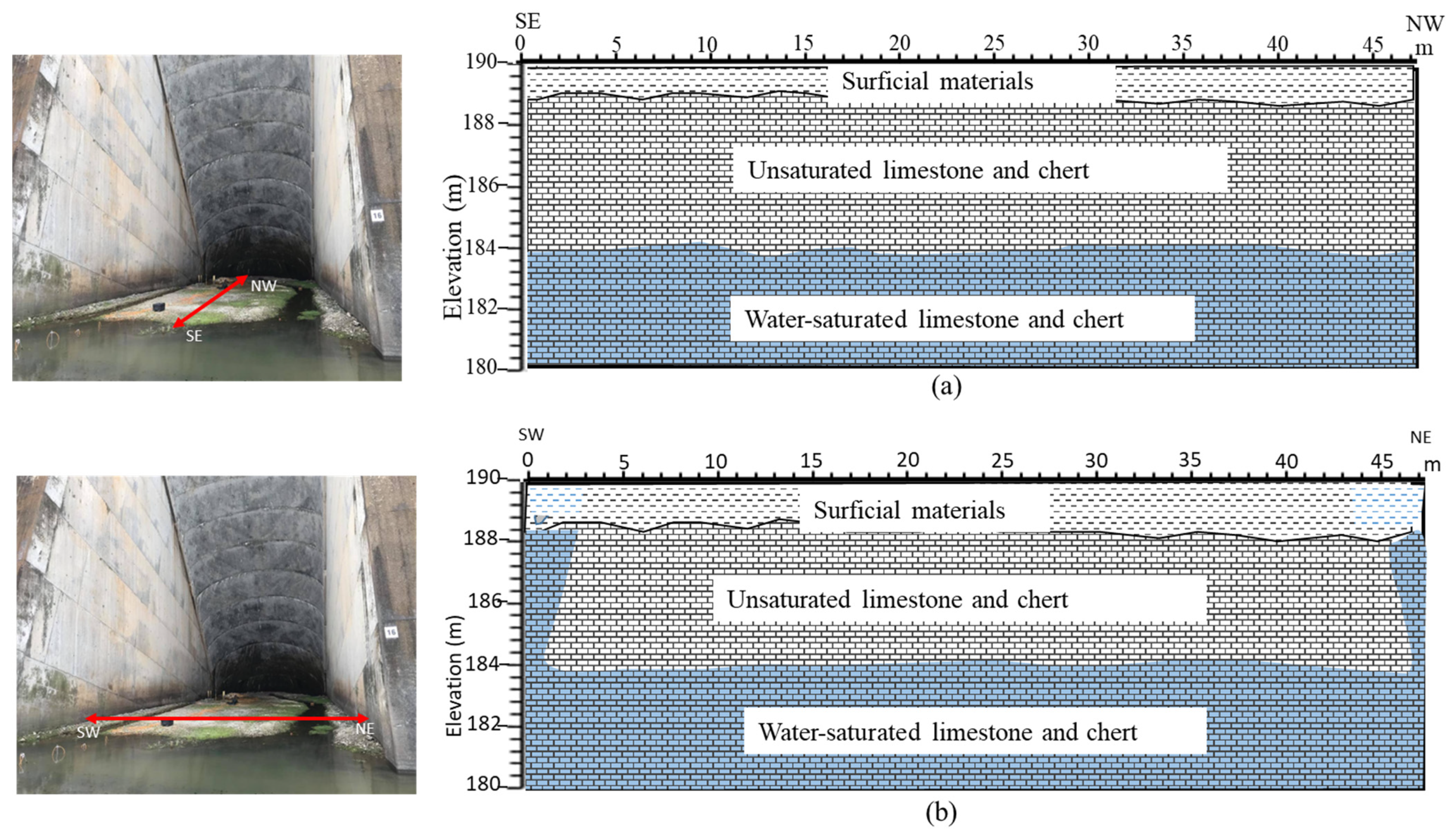
The results of the multiple geophysical surveys conducted inside the two arches were integrated to better understand the geological/hydrological conditions of the dam rock foundations and investigate the anomalous water seepage problem at this specific location. Figure 21 illustrates two suggested models that interpret the subsurface conditions below the arches. One subsurface model is oriented perpendicular to the axis of dam (Figure 21a), while the other is parallel to the dam axis (Figure 21b). Both models show the dam foundation rock of the Reeds Spring Formation overlain by an average 2 m of surficial materials (Figure 21). The upper 5 m of the dam foundation rock appears to be less pervious (unsaturated limestone and chert), possibly preventing horizontal or vertical groundwater flow through it. The unsaturated characteristic of this layer is most likely because the chert within the limestone in this layer has more interlocking lithologic bodies [1]. A water-saturated limestone and chert layer appeared at an elevation of ~184 m and underlies the unsaturated limestone and chert.
The SW-NE geological model (Figure 21b) shows similar features to the SE-NW model except for the zones in the vicinity of the buttress walls. The model indicated relatively high moisture content and possible fractures close to the buttress walls in the two arches.
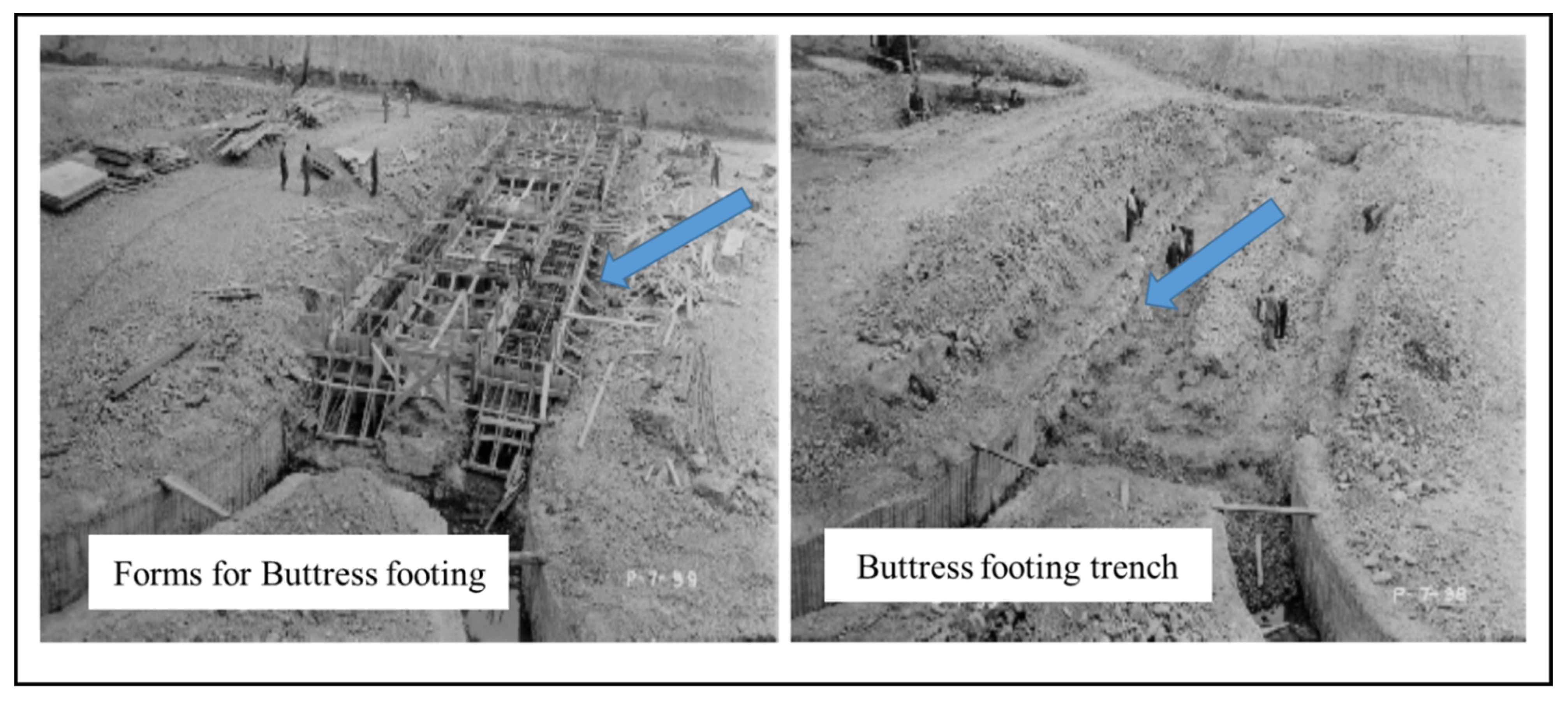
Blasting of the dam foundation rock and the placement of the arch/buttress concrete footing (Figure 22) may have created shallow vertical surfaces on both sides of the concrete placement, creating small water pathways within the more hydraulically restrictive unsaturated rock unit [69,70]. In addition, lateral flow paths are possible along the concrete foundation contact with rock. Other artesian conditions are likely the vertical, seemingly random, locations from old joint systems or recent activities in the investigation or construction of the dam or maintenance impacts. These “random” artesian conditions are exhibited within the two arches, but most notably at Arch-16.
The conditions of the dam foundation rocks may have been modified by post dam construction mainly due to recent excavation, construction, and new pool gradient beneath the dam, dominantly transmitting its release of the large pressure head of the reservoir and the Boone aquifer’s pressure head in the near horizontal bedding planes. The fractures in the subsurface beneath the arches seem to be dipping in different directions within the Reeds Spring Formation [1] and this probably allows for vertical routes of water passage. This fracture system may have been developed over geologic time within the incision of the valley. The vertical and lateral hydraulic conductivity of the Pensacola Dam foundation rock may have been altered further by investigation borings, blasting and excavation of the dam’s foundation, placement of the concrete arched structure, activation of the new vertical and downstream berm horizontal forces on the dam by the reservoir filling. The SP anomalies beneath Arch-16, especially for profiles near the buttress walls, are predominantly positive which indicates that the anomalous seepage beneath Arch-16 is being channeled vertically in a direction towards the surface [64].
The integration of the geophysical results for the downstream berm area generally showed similar subsurface models as the arches with three subsurface layers including (from top to bottom): the surficial materials and fill, the unsaturated limestone and chert, and the water-saturated limestone and chert. The unsaturated limestone and chert layer occurred at an elevation of ~190 m amsl in the downstream berm, with thickness ranging from 12 to 15 m. The fracture zones that correspond to the buttress location in front of the arches are most likely fractured limestone that resulted from previous foundation rock blasting [1]. The underlying water-saturated foundation rock occurred at an elevation of ~175 m amsl at this specific location. The MASW profile did not image the interface between the unsaturated limestone and chert layer and the water-saturated limestone and chert layer. This confirmed that the dam foundation rock is the same unit at the dam, but the low resistivity layer (water-saturated limestone and chert) is due to the high moisture content.
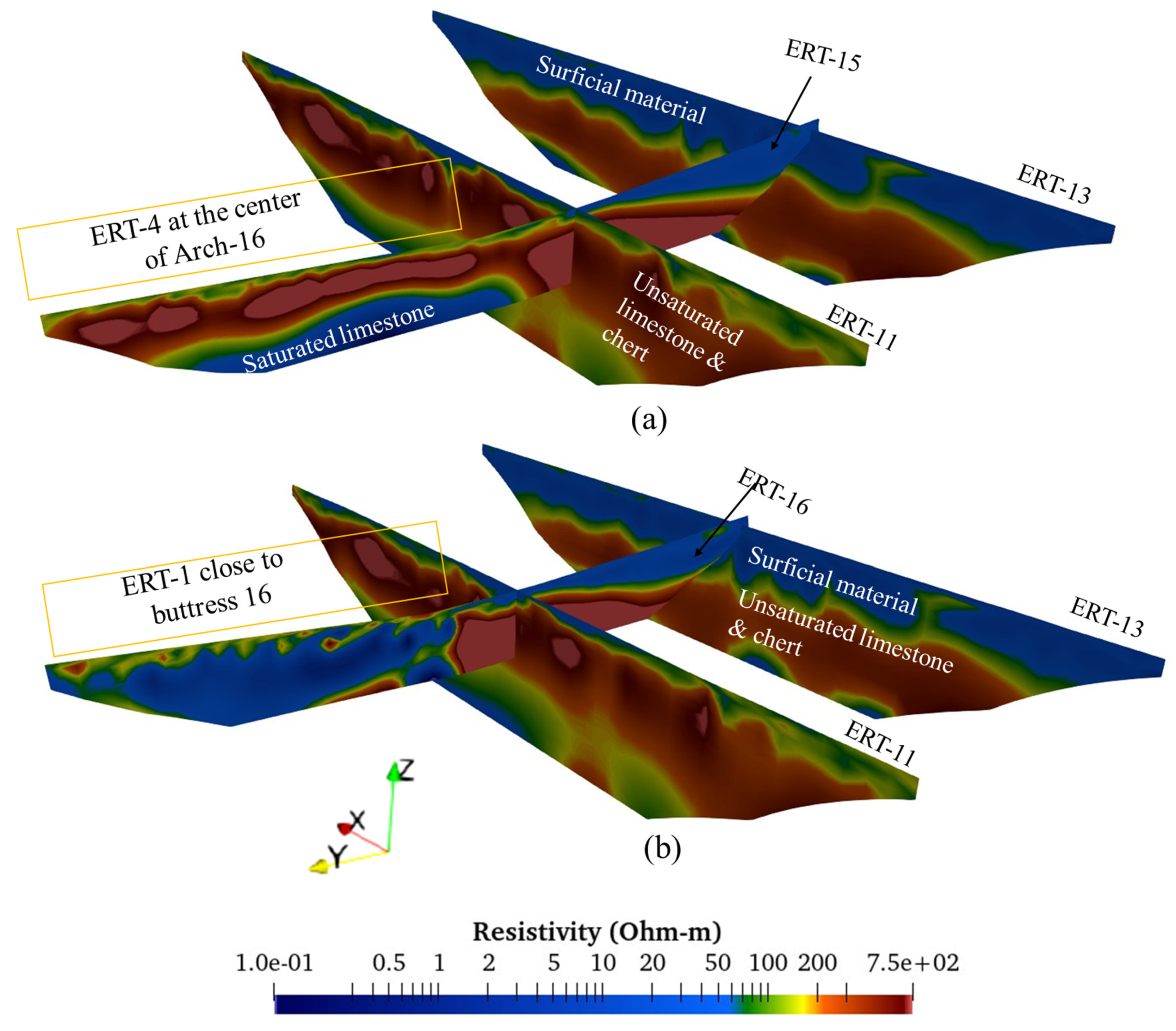
Although the geophysical surveys inside the arches and along the downstream berm showed comparable subsurface three-layer models, the water-saturated limestone and chert layer were delineated at a much shallower depth under the arches compared to the downstream berm areas. The acquired ERT-15 and ERT-16 (when displayed together with ERT-11 and ERT-13 using ParaView 5.10.1) confirmed the dramatic change in the elevation of the water-saturated limestone and chert layer inside the arches and the downstream berm (Figure 23a,b). The higher elevation of the water-saturated limestone chert under the arches may be attributed to the uplift pressure beneath the dam base. Pressure exerted by the arch dam structure increases the groundwater level under the arch by increasing the pressure of the water against the underlying foundation rock. This increased pressure forces the water to seep through the structure, which increases the water pressure underneath the arch and causes the groundwater level to rise [69]. The pressure causes the groundwater to flow towards the downstream berm due to the pressure difference between the foundation rock beneath the base of the dam and the downstream berm. The pressure created by the arch dam is probably greater than the atmospheric pressure, and as a result, the groundwater flows from the higher pressure under the arch to the lower pressure in the downstream berm [71,72].
The water flowing from the two wells inside Arch-16 shows similar characteristics, which are different from the lake water as indicated by the concentrations of Ca2+, TA, TH, TDS, EC, nitrate, K+, pH, and dissolved oxygen. This suggested that the water seeping in Arch-16 may either be a mixture of groundwater and lake water percolating through fractures to the surface or lake water interacting with rock fractures. Although the chemical characteristics of lake water and Arch-16 wells are different, this interpretation is only based on two available wells and more sampling and further analyses such as isotope analyses [73,74] may be required to support this interpretation.

7. Conclusions

The integrated geophysical surveys in this study including ERT, SP, seismic P-wave refraction, MASW, and S-wave reflection have characterized the dam foundation rock and delineated seepage zones at two structural arches and part of the downstream berm of Pensacola Dam. The study characterized the dam foundation rock under the arches and the downstream berm as an unsaturated limestone and chert layer overlying a water-saturated layer. The geophysical results showed the groundwater at a much higher elevation beneath the base of the dam compared to that under the downstream berm, which may be due to the uplift pressure beneath the dam. The unsaturated limestone close to the buttress walls in the arches showed evidence of water seepage indicating that the layer may have been altered by blasting and excavation of the dam’s foundation, placement of the concrete, and/or improper grouting closure of drill holes. The lateral hydraulic conductivity within these rock units is locally changed to vertical, seemingly random, joint system conduits through the unsaturated layer, causing the artesian conditions inside some of the arches, notably inside Arch-16. Based on the geochemical analysis, the lake water and artesian wells’ water from Arch-16 have noticeably different chemical characteristics. The implication of this is that the seeps in Arch-16 could be a mixture of groundwater and lake water or lake water interacting with rock and finding its way to the surface through fractures. However, as few water samples were used for this analysis, more sampling and further analysis are required to confirm the main source of the water from Arch-16. Evaluating the geophysical methods utilized in this study indicated that the optimum geophysical methods to characterize the dam foundation rock and delineate seepage problems beneath the arches of the dam included ERT, SP, and seismic P-wave refraction methods. For imaging the embankment fill and determining the rock surface and rock weathering along the downstream berm, S-wave reflection, ERT, and MASW are recommended. To confirm and correlate the water seepage along the footings of the arches, we suggest the excavation and in-place coring of the surficial rock. While additional data are required to validate the outcomes of this study, the results can serve as an initial geophysical baseline to maximize relative comparative repeatability and develop an effective monitoring system. Future long-term optimization of seepage monitoring at the dam would benefit from the integration of time-lapse ERT and SP data. This study showcases the effectiveness of combining geophysical surveys and geochemical analysis in resolving a challenging dam safety problem. Our findings highlight the significant advantages derived from this integrated approach, emphasizing its role as a global best practice for comprehensive dam safety investigations.

Author Contributions

Conceptualization, O.S. and A.I.; methodology, O.S. and A.I.; field investigation, O.S. and A.I.; result analysis, O.S.; writing—original draft preparation, O.S.; writing—review and editing, O.S. and A.I.; funding acquisition, A.I. All authors have read and agreed to the published version of the manuscript.

Funding

This research was funded by Grand River Dam Authority (GRDA).

Data Availability Statement

The data presented in this study are available on request from the corresponding author. The data are not publicly available due to privacy issues.

Acknowledgments

The authors would like to thank the Grand River Dam Authority (GRDA) for funding this research and for providing accessibility to the dam. The technical assistance of Daniel Laó-Dávila, Farag Mewafy, and Melina Lazar contributed immensely to this study. Zonaed Sazal and Patrick Meese are thanked for their assistance during data acquisition. The authors also appreciate the High-Performance Computer Center of Oklahoma State University for the provision of Landmark Seisspace software used for seismic data processing.

Conflicts of Interest

The authors declare no conflict of interest. The funders approved the decision to publish the results.

References

  1. Grand River Dam Authority (GRDA). Solutions for Evaluating, Monitoring, and Improving Dam Foundation Conditions of the Pensacola Dam, R.S. Kerr Dam, and the Salina Pumped Storage Project, No. 42584; Unpublished Technical Report; GRDA: Langley, OK, USA, 2022. [Google Scholar]
  2. Ouhichi, N.; Hamdi, R.; Lachaal, F.; Gabtni, H.; Grünberger, O. Geophysical and hydrogeological investigations of water leakage from a reservoir dam to a coastal aquifer: The Lebna Case Study (Northeastern Tunisia). Arab. J. Geosci. 2022, 15, 1192. [Google Scholar] [CrossRef]
  3. Zhang, H.; Jing, Y.; Chen, J.; Gao, Z.; Xu, Y. Characteristics and causes of crest cracking on a high core-wall rockfill dam: A case study. Eng. Geol. 2022, 297, 106488. [Google Scholar] [CrossRef]
  4. Haghighi, A.T.; Tuomela, A.; Hekmatzadeh, A.A. Assessing the Efficiency of Seepage Control Measures in Earthfill Dams. Geotech. Geol. Eng. 2020, 38, 5667–5680. [Google Scholar] [CrossRef]
  5. Ikard, S.J.; Rittgers, J.; Revil, A.; Mooney, M.A. Geophysical Investigation of Seepage Beneath an Earthen Dam. Groundwater 2014, 53, 238–250. [Google Scholar] [CrossRef]
  6. Sazal, Z.; Sanuade, O.; Ismail, A. Geophysical Characterization of the Carl Blackwell Earth-Fill Dam: Stillwater, Oklahoma, USA. Pure Appl. Geophys. 2022, 179, 2853–2867. [Google Scholar] [CrossRef]
  7. Raji, W.O.; Adedoyin, A.D. Dam safety assessment using 2D electrical resistivity geophysical survey and geological mapping. J. King Saud Univ. Sci. 2020, 32, 1123–1129. [Google Scholar] [CrossRef]
  8. Camarero, P.L.; Moreira, C.A.; Pereira, H.G. Analysis of the Physical Integrity of Earth Dams from Electrical Resistivity Tomography (ERT) in Brazil. Pure Appl. Geophys. 2019, 176, 5363–5375. [Google Scholar] [CrossRef]
  9. Rahimi, S.; Moody, T.; Wood, C.; Kouchaki, B.M.; Barry, M.; Tran, K.; King, C. Mapping Subsurface Conditions and Detecting Seepage Channels for an Embankment Dam Using Geophysical Methods: A Case Study of the Kinion Lake Dam. J. Environ. Eng. Geophys. 2019, 24, 373–386. [Google Scholar] [CrossRef]
  10. Camarero, P.L.; Moreira, C.A. Geophysical investigation of earth dam using the electrical tomography resistivity technique. REM Int. Eng. J. 2017, 70, 47–52. [Google Scholar] [CrossRef]
  11. Dai, Q.; Lin, F.; Wang, X.; Feng, D.; Bayless, R.C. Detection of concrete dam leakage using an integrated geophysical technique based on flow-field fitting method. J. Appl. Geophys. 2017, 140, 168–176. [Google Scholar] [CrossRef]
  12. Loperte, A.; Soldovieri, F.; Palombo, A.; Santini, F.; Lapenna, V. An integrated geophysical approach for water infiltration detection and characterization at Monte Cotugno rock-fill dam (southern Italy). Eng. Geol. 2016, 211, 162–170. [Google Scholar] [CrossRef]
  13. Bedrosian, P.A.; Burton, B.L.; Powers, M.H.; Minsley, B.J.; Phillips, J.D.; Hunter, L.E. Geophysical investigations of geology and structure at the Martis Creek Dam, Truckee, California. J. Appl. Geophys. 2012, 77, 7–20. [Google Scholar] [CrossRef]
  14. Takamte, C.R.M.; Ntomba, S.M.; Atouba, L.C.O.; Bisso, D.; Ondoa, J.M. Geophysical and geological considerations for characterizing the dam foundation during the Memve’ele dam construction (southern Cameroon): Influence on the dam type retained. Environ. Earth Sci. 2022, 81, 343. [Google Scholar] [CrossRef]
  15. Cardarelli, E.; Cercato, M.; De Donno, G. Characterization of an earth-filled dam through the combined use of electrical resistivity tomography, P- and SH-wave seismic tomography and surface wave data. J. Appl. Geophys. 2014, 106, 87–95. [Google Scholar] [CrossRef]
  16. Loke, M.H.; Barker, R.D. Least-squares deconvolution of apparent resistivity pseudosections. Geophysics 1995, 60, 1682–1690. [Google Scholar] [CrossRef]
  17. Griffiths, D.H.; Barker, R.D. Two-dimensional resistivity imaging and modelling in areas of complex geology. J. Appl. Geophys. 1993, 29, 211–226. [Google Scholar] [CrossRef]
  18. Dey, A.; Morrison, H.F. Resistivity modeling for arbitrary shaped three-dimensional structures. Geophysics 1979, 44, 753–780. [Google Scholar] [CrossRef]
  19. Rehman, F.; Sherif, M.E.; Ali, H.A.; Hussein, M.H. Multichannel analysis of surface waves (MASW) for seismic site characterization using 2D genetic algorithm at Bahrah area, Wadi Fatima, Saudi Arabia. Arab. J. Geosci. 2016, 9, 519. [Google Scholar] [CrossRef]
  20. Guo, Y.; Cui, Y.-A.; Xie, J.; Luo, Y.; Zhang, P.; Liu, H.; Liu, J. Seepage detection in earth-filled dam from self-potential and electrical resistivity tomography. Eng. Geol. 2022, 306, 106750. [Google Scholar] [CrossRef]
  21. Vagnon, F.; Comina, C.; Arato, A. Evaluation of different methods for deriving geotechnical parameters from electric and seismic streamer data. Eng. Geol. 2022, 303, 106670. [Google Scholar] [CrossRef]
  22. Yari, M.; Nabi-Bidhendi, M.; Ghanati, R.; Shomali, Z.H. Hidden layer imaging using joint inversion of P-wave travel-time and electrical resistivity data. Near Surf. Geophys. 2021, 19, 297–313. [Google Scholar] [CrossRef]
  23. Himi, M.; Casado, I.; Sendros, A.; Lovera, R.; Rivero, L.; Casas, A. Assessing preferential seepage and monitoring mortar injection through an earthen dam settled over a gypsiferous substrate using combined geophysical methods. Eng. Geol. 2018, 246, 212–221. [Google Scholar] [CrossRef]
  24. Cardarelli, E.; Cercato, M.; De Donno, G. Surface and borehole geophysics for the rehabilitation of a concrete dam (Penne, Central Italy). Eng. Geol. 2018, 241, 1–10. [Google Scholar] [CrossRef]
  25. Martínez-Moreno, F.J.; Delgado-Ramos, F.; Galindo-Zaldívar, J.; Martín-Rosales, W.; López-Chicano, M.; González-Castillo, L. Identification of leakage and potential areas for internal erosion combining ERT and IP techniques at the Negratín Dam left abutment (Granada, southern Spain). Eng. Geol. 2018, 240, 74–80. [Google Scholar] [CrossRef]
  26. Abdulsamad, F.; Revil, A.; Ahmed, A.S.; Coperey, A.; Karaoulis, M.; Nicaise, S.; Peyras, L. Induced polarization tomography applied to the detection and the monitoring of leaks in embankments. Eng. Geol. 2019, 254, 89–101. [Google Scholar] [CrossRef]
  27. Al-Fares, W.; Al-Hilal, M. Integration of electrical resistivity tomography with electromagnetic and soil radon measurements for characterizing the leakage problem in Afamia B dam, Syria. Geofísica Int. 2018, 57, 275–287. [Google Scholar] [CrossRef]
  28. Ismail, A.; Anderson, N. 2-D and 3-D Resistivity Imaging of Karst Sites in Missouri, USA. Environ. Eng. Geosci. 2012, 18, 281–293. [Google Scholar] [CrossRef]
  29. Kemna, A.; Binley, A.; Slater, L. Crosshole IP imaging for engineering and environmental applications. Geophysics 2004, 69, 97–107. [Google Scholar] [CrossRef]
  30. Slater, L.D.; Lesmes, D. IP interpretation in environmental investigations. Geophysics 2002, 67, 77–88. [Google Scholar] [CrossRef]
  31. Ahmed, A.S.; Revil, A.; Bolève, A.; Steck, B.; Vergniault, C.; Courivaud, J.; Jougnot, D.; Abbas, M. Determination of the permeability of seepage flow paths in dams from self-potential measurements. Eng. Geol. 2020, 268, 105514. [Google Scholar] [CrossRef]
  32. Ahmed, A.S.; Revil, A.; Steck, B.; Vergniault, C.; Jardani, A.; Vinceslas, G. Self-potential signals associated with localized leaks in embankment dams and dikes. Eng. Geol. 2019, 253, 229–239. [Google Scholar] [CrossRef]
  33. Bogoslovsky, V.A.; Ogilvy, A.A. The study of streaming potentials on fissured media models. Geophys. Prospect. 1972, 20, 109–117. [Google Scholar] [CrossRef]
  34. Rittgers, J.B.; Revil, A.; Planès, T.; Mooney, M.A.; Koelewijn, A.R. 4-D imaging of seepage in earthen embankments with time-lapse inversion of self-potential data constrained by acoustic emissions localization. Geophys. J. Int. 2015, 200, 758–772. [Google Scholar] [CrossRef]
  35. Bolève, A.; Vandemeulebrouck, J.; Grangeon, J. Dyke leakage localization and hydraulic permeability estimation through self-potential and hydro-acoustic measurements: Self-potential ‘abacus’ diagram for hydraulic permeability estimation and uncertainty computation. J. Appl. Geophys. 2012, 86, 17–28. [Google Scholar] [CrossRef]
  36. Woolery, E.W. SH-Mode Seismic-Reflection Imaging of Earthfill Dams. Engineering 2018, 4, 694–701. [Google Scholar] [CrossRef]
  37. Busato, L.; Boaga, J.; Peruzzo, L.; Himi, M.; Cola, S.; Bersan, S.; Cassiani, G. Combined geophysical surveys for the characterization of a reconstructed river embankment. Eng. Geol. 2016, 211, 74–84. [Google Scholar] [CrossRef]
  38. Xia, J.; Cakir, R.; Miller, R.D.; Zeng, C.; Luo, Y. Estimation of near-surface shear-wave velocity by inversion of Love waves. In SEG Technical Program Expanded Abstracts; Society of Exploration Geophysicists: Houston, TX, USA, 2009. [Google Scholar]
  39. Lorenzi, V.; Barberio, M.D.; Sbarbati, C.; Petitta, M. Groundwater recharge distribution due to snow cover in shortage conditions (2019–22) on the Gran Sasso carbonate aquifer (Central Italy). Environ. Earth Sci. 2023, 82, 206. [Google Scholar] [CrossRef]
  40. Medici, G.; Langman, J.B. Pathways and Estimate of Aquifer Recharge in a Flood Basalt Terrain; A Review from the South Fork Palouse River Basin (Columbia River Plateau, USA). Sustainability 2022, 14, 11349. [Google Scholar] [CrossRef]
  41. Wu, X.; Li, C.; Sun, B.; Geng, F.; Gao, S.; Lv, M.; Ma, X.; Li, H.; Xing, L. Groundwater hydrogeochemical formation and evolution in a karst aquifer system affected by anthropogenic impacts. Environ. Geochem. Health 2020, 42, 2609–2626. [Google Scholar] [CrossRef]
  42. Domrocheva, E.V.; Kuzevanov, K.I.; Gridasov, A.G.; Sizikov, D.A. Hydrogeological conditions of Naryk-ostashkin area in Erunakovo region in Kuzbass. Bull. Tomsk Polytech. Univ.-Geo Assets Eng. 2018, 329, 134–142. [Google Scholar] [CrossRef]
  43. Mostafa, M.G.; Uddin, S.M.H.; Haque, A.B.M.H. Assessment of hydro-geochemistry and groundwater quality of Rajshahi City in Bangladesh. Appl. Water Sci. 2017, 7, 4663–4671. [Google Scholar] [CrossRef]
  44. Warth, P.; Polone, D.J. Soil survey of Adair County, Oklahoma; U.S. Department of Agriculture Soil Conservation Service Series; Facsimile Publisher: New York, NY, USA, 1965; 61p. [Google Scholar]
  45. Huffman, G.G. Geology of the flanks of the Ozark Uplift; Oklahoma Geological Survey Bulletin; Oklahoma Geological Survey: Norman, OK, USA, 1958; Volume 77, 281p. [Google Scholar]
  46. Marcher, M.V.; Bingham, R.H. Reconnaissance of the water resources of the Tulsa Quadrangle, Northeastern Oklahoma. Oklahoma Geological Survey Hydrologic Atlas 1971, 2, 4 Sheets, Scale 1:250,000. Available online: pubs.usgs.gov/wri/wri954150/pdf/wri954150.pdf (accessed on 1 November 2023).
  47. Osborn, N.I.; Minor Basin Hydrogeologic Investigation Report of the Boone Groundwater Basin; Northeastern Oklahoma. Oklahoma Water Resources Board Technical Report; 2001, GW2001-2. Available online: https://www.oklahoma.gov/content/dam/ok/en/owrb/documents/science-and-research/hydrologic-investigations/boone-2001.pdf (accessed on 1 November 2023).
  48. Grand River Dam Authority (GRDA). Report on Foundation Exploration and Geologic Design Parameters; Unpublished Technical Report; GRDA: Langley, OK, USA, 1995; Volume I, No. 1494-OK. [Google Scholar]
  49. Christenson, S.C. Contamination of Wells Completed in the Roubidoux Aquifer by Abandoned Zinc and Lead Mines, Ottawa County, Oklahoma. U.S. Geological Survey Water-Resources Investigations Report 1995-4150. 114p. Available online: chrome-extension://efaidnbmnnnibpcajpcglclefindmkaj/https://pubs.usgs.gov/wri/wri954150/pdf/wri954150.pdf (accessed on 1 November 2023).
  50. Grand River Dam Authority (GRDA). Supporting Technical Information Document for the Salina Pumped Storage Project, No. 2524; Unpublished Technical Report; GRDA: Langley, OK, USA, 2017. [Google Scholar]
  51. Mazzullo, S.J.; Boardman, D.R.; Wilhite, B.W.; Godwin, C.; Morris, B.T. Revisions of outcrop lithostratigraphic nomenclature in the Lower to Middle Mississippian subsystem (Kinderhookian to Basal Meramecian Series) along the shelf-Edge in Southwest Missouri, Northwest Arkansas, and Northeast Oklahoma. Shale Shaker 2013, 63, 414–454. [Google Scholar]
  52. Swindle, A. Water Chemistry of Selected Springs, Boone Aquifer, Delaware County, Oklahoma. Ph.D. Thesis, Oklahoma State University, Stillwater, OK, USA, 2003. [Google Scholar]
  53. Imes, J.L.; Emmett, L.F. Geohydrology of the Ozarks Plateaus Aquifer System in Parts of Missouri, Arkansas, Oklahoma, and Kansas. U.S. Geological Survey Professional Paper 1994, 1414-D. 127p. Available online: https://pubs.usgs.gov/pp/1414d/report.pdf (accessed on 5 November 2023).
  54. Loke, M.; Barker, R. Rapid least-squares inversion of apparent resistivity pseudosections by a quasi-Newton method1. Geophys. Prospect. 1996, 44, 131–152. [Google Scholar] [CrossRef]
  55. deGroot-Hedlin, C.; Constable, S. Occam’s inversion to generate smooth, two-dimensional models from magnetotelluric data. Geophysics 1990, 55, 1613–1624. [Google Scholar] [CrossRef]
  56. Geometrics. Seisimager/2D Refraction Software. 2019. Available online: https://www.geometrics.com/software/seisimager-2d/ (accessed on 18 October 2023).
  57. Sheehan, J.R.; Doll, W.E.; Mandell, W.A. An Evaluation of Methods and Available Software for Seismic Refraction Tomography Analysis. J. Environ. Eng. Geophys. 2005, 10, 21–34. [Google Scholar] [CrossRef]
  58. Zhang, J.; Toksöz, M.N. Nonlinear refraction traveltime tomography. Geophysics 1998, 63, 1726–1737. [Google Scholar] [CrossRef]
  59. Kansas Geological Survey 2019. Surfseis MASW Software. Available online: http://www.kgs.ku.edu/software/surfseis/index.html (accessed on 18 October 2023).
  60. Xiao, C.; Bancroft, J.C.; Brown, R.J. Estimation of Thomsen’s anisotropy parameters by moveout velocity analysis. In SEG Technical Program Expanded Abstracts 2005; Society of Exploration Geophysicists: Houston, TX, USA; pp. 194–197. [CrossRef]
  61. Treitel, S. The complex wiener filter. Geophysics 1974, 39, 169–173. [Google Scholar] [CrossRef]
  62. Richards, L.A. Diagnosis and Improvement of Saline and Alkali Soils. In USDA Handbook No. 60. 1954; US Government Printing Office: Washington, DC, USA, 1954. [Google Scholar] [CrossRef]
  63. Standard Methods for the Examination of Water and Wastewater (SMEWW), 19th ed.; American Public Health Association: Washington, DC, USA, 1995.
  64. Rittgers, J.B.; Revil, A.; Karaoulis, M.; Mooney, M.A.; Slater, L.D.; Atekwana, E.A. Self-potential signals generated by the corrosion of buried metallic objects with application to contaminant plumes. Geophysics 2013, 78, EN65–EN82. [Google Scholar] [CrossRef]
  65. Dahlin, T. 2D resistivity surveying for environmental and engineering applications. First Break. 1996, 14, 275–283. [Google Scholar] [CrossRef]
  66. Sjödahl, P.; Dahlin, T.; Zhou, B. 2.5D resistivity modeling of embankment dams to assess influence from geometry and material properties. Geophysics 2006, 71, G107–G114. [Google Scholar] [CrossRef]
  67. Yang, X.; Lagmanson, M. Comparison of 2D and 3D electrical resistivity imaging methods. In Proceedings of the Symposium on the Application of Geophysics to Engineering and Environmental Problems, Seattle, WA, USA, 2–6 April 2006; Society of Exploration Geophysicists: Houston, TX, USA; pp. 585–594. [Google Scholar]
  68. Hung, Y.-C.; Lin, C.-P.; Lee, C.-T.; Weng, K.-W. 3D and Boundary Effects on 2D Electrical Resistivity Tomography. Appl. Sci. 2019, 9, 2963. [Google Scholar] [CrossRef]
  69. Liu, G.; Lu, W.; Niu, X.; Wang, G.; Chen, M.; Yan, P. Excavation Shaping and Damage Control Technique for the Breccia Lava Dam Foundation at the Bai-he-tan Hydropower Station: A Case Study. Rock Mech. Rock Eng. 2020, 53, 1889–1907. [Google Scholar] [CrossRef]
  70. Wu, F.; Liu, T.; Liu, J.; Tang, X. Excavation unloading destruction phenomena in rock dam foundations. Bull. Eng. Geol. Environ. 2009, 68, 257–262. [Google Scholar] [CrossRef]
  71. Çelik, R. Impact of Dams on Groundwater Static Water Level Changes: A Case Study Kralkızı and Dicle Dam Watershed. Int. J. Eng. Res. Dev. 2018, 10, 119–126. [Google Scholar] [CrossRef]
  72. Janzen, K.; Westbrook, C.J. Hyporheic Flows Along a Channelled Peatland: Influence of Beaver Dams. Can. Water Resour. J. Rev. Can. Ressour. Hydr. 2011, 36, 331–347. [Google Scholar] [CrossRef]
  73. Quilis, R.O.; Hoogmoed, M.; Ertsen, M.; Foppen, J.W.; Hut, R.; de Vries, A. Measuring and modeling hydrological processes of sand-storage dams on different spatial scales. Phys. Chem. Earth Parts A/B/C 2009, 34, 289–298. [Google Scholar] [CrossRef]
  74. Yi, P.; Yang, J.; Wang, Y.; Mugwanezal, V.d.P.; Chen, L.; Aldahan, A. Detecting the leakage source of a reservoir using isotopes. J. Environ. Radioact. 2018, 187, 106–114. [Google Scholar] [CrossRef]
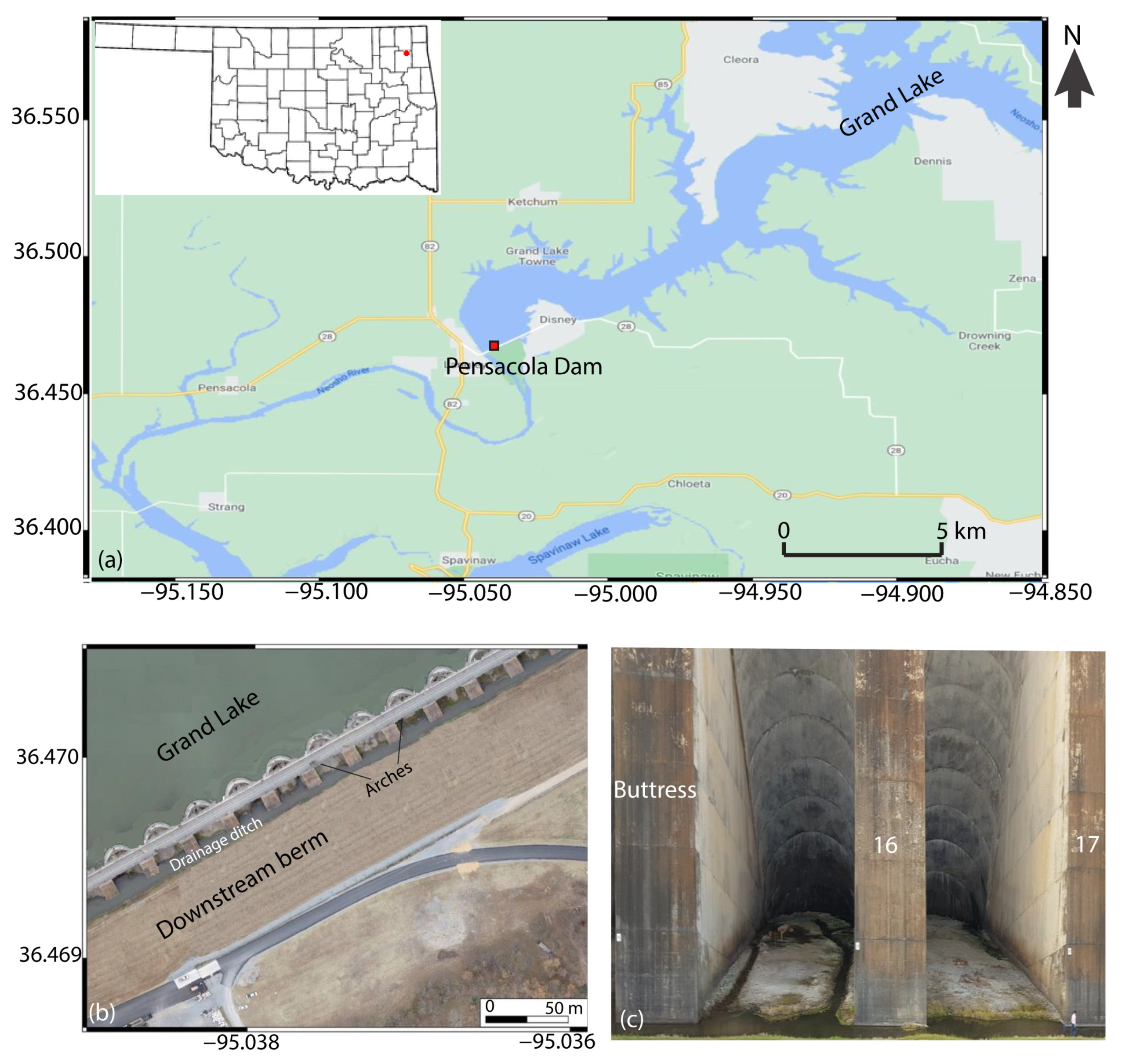
Figure 1. A map of the study area. (a) The location of Pensacola Dam in Mayes County; (b) the downstream berm and arches of the Pensacola Dam; (c) a photo of Arch-16 and Arch-17. The dam’s structure comprises multiple concrete arches (various types of aggregate materials such as crushed stones and sand were mixed with the concrete), which are reinforced with steel. The grout, a mixture of cement, sand, and water, was used to fill voids and provide additional support and stability. The downstream berm comprises compacted earth and rock fills.
Water 15 04036 g001
Figure 2. A generalized stratigraphic column of northeastern Oklahoma displaying the formations present at the Pensacola Dam (modified after [45]). The red box represents the stratigraphy at Pensacola Dam.
Water 15 04036 g002
Figure 3. Cross section of Arch-16 and Arch-17 showing the reference geological stratigraphy between boreholes B16 and B17.
Water 15 04036 g003
Figure 4. Stratigraphic column of northeastern Oklahoma showing the hydrologic unit (modified after [47]). Note: The names in the geohydrologic unit that are in parenthesis represent the names given by the United States Geological Survey. Ls = limestone; Sh = shale; Ss = sandstone; Fm = Formation.
Water 15 04036 g004
Figure 5. A map of Pensacola Dam showing the three tested locations. The tested locations are shown in red.
Water 15 04036 g005
Figure 6. Location of the acquired ERT, SP, and seismic P-wave refraction geophysical profiles and borehole inside Arch-16 and Arch-17 at Pensacola Dam. The orange dot represents the boreholes. Not drawn to scale.
Water 15 04036 g006
Figure 7. Location of the geophysical survey lines acquired at the downstream berm of Pensacola Dam.
Water 15 04036 g007
Figure 8. MASW survey. (a) Example of shot gather at the dam; (b) phase velocity-frequency spectrum of the shot gather in (a).
Water 15 04036 g008
Figure 9. ERT profiles acquired inside Arch-16 at Pensacola Dam. (a) ERT-1; (b) ERT-2; (c) ERT-3; (d) ERT-4; (e) ERT-5; (f) ERT-6. The vertical dashed lines across all the profiles are interpreted as water-saturated vertical jointing or fractured zone.
Water 15 04036 g009
Figure 10. SP contour map showing the variation of the SP values over the area inside Arch-16. The small black dots represent the SP stations. Zones 1 to 3 are interpreted as the potential seepage pathways within Arch-16. The map was generated using the kriging gridding method.
Water 15 04036 g010
Figure 11. Pseudo 3D resistivity volume generated from the interpolation of the 2D six resistivity profiles acquired inside Arch-16 at Pensacola Dam. The 3D volume is sliced at 1 m (a), 3 m (b), 5 m, (c) and 8 m (d). Note that the E-W low resistivity linear feature between distance marks 33 and 36 m, indicated by the red arrow, is interpreted as a vertical fracture at this location.
Water 15 04036 g011
Figure 12. ERT profiles acquired inside Arch-17 at Pensacola Dam. (a) ERT-7 next to Buttress 18; (b) ERT-8 at the center of Arch-17; (c) ERT-9 next to Buttress 16. Borehole “B17” shows both the unsaturated limestone chert and water-saturated limestone and chert as one layer.
Water 15 04036 g012
Figure 13. Seismic refraction profiles acquired inside Arch-16 at Pensacola Dam. (a) Seismic refraction profile 1; (b) seismic refraction profile 2; (c) seismic refraction profile 3; (d) seismic refraction profile 4; (e) seismic refraction profile 5; (f) seismic refraction profile 6.
Water 15 04036 g013
Figure 14. The three geophysical profiles in front of the arches centered around Arch-16 at Pensacola Dam. (a) Location map, (b) ERT, (c) MASW, and (d) S-wave reflection. The x-axis represents the horizontal distance in meters, while the y-axis represents the elevation in meters. The black arrows on the ERT model are interpreted as fracture zones.
Water 15 04036 g014
Figure 15. ERT profiles along the downstream berm showing three resistivity layers. (a) Location map, (b) ERT-11, (c) ERT-12, (d) ERT-13.
Water 15 04036 g015
Figure 16. Geophysical profiles acquired at the top of the slope in the downstream berm section at Pensacola Dam. (a) Location map, (b) 2D ERT, and (c) 2D S-wave reflection profile. The x-axis represents the horizontal distance in meters, while the y-axis represents the elevation in meters.
Water 15 04036 g016
Figure 17. Example of 1D MASW inversion. (a) Mean model (black solid line) and minimum misfit model (red solid line); (b) Vs uncertainty estimation, ΔVs; (c) layer thickness uncertainty estimation, Δt.
Water 15 04036 g017
Figure 18. (a) Location map (b) 2D MASW profile acquired at the top of the slope in the downstream berm section at Pensacola Dam. The x-axis represents the horizontal distance in meters, while the y-axis represents the elevation in meters.
Water 15 04036 g018
Figure 19. Two ERT profiles acquired perpendicular to the axis of the dam. (a) Location map, (b) ERT-15, (c) ERT-16. The red arrows are the locations of ERT profiles 11, 12, 13, and 14 in Figure 16 and Figure 17 along the downstream berm. The black dashed line labeled “top of saturated limestone and chert” was estimated based on the elevations of water-saturated limestone and chert layer in crossing ERT profiles 11–14. The red arrows represent the locations of the crossing ERT profiles 11–14 in Figure 15b–d and Figure 16b.
Water 15 04036 g019
Figure 20. Geochemical values of water samples collected at Pensacola Dam.
Water 15 04036 g020
Figure 21. A combined geophysical interpretation (ERT, SP, and seismic P-wave refraction). (a) SW-NE geological model; (b) SE-NW geological model.
Water 15 04036 g021
Figure 22. Field photos taken during the construction of Pensacola Dam showing the excavation of the foundation rock for the buttress and arches’ foundations. The blue arrow shows the placement of the arch/buttress concrete footing which may have created shallow vertical surfaces.
Water 15 04036 g022
Figure 23. A combined display of ERT-11 and ERT-13 profiles along the downstream berm and ERT- 15 (a), and ERT-16 profiles (b) perpendicular to the axis of the dam. The figure shows the drastic change in the elevation of the water-saturated limestone and chert layer under the arches and beneath the downstream berm.
Water 15 04036 g023
Table 1. Summary of data acquisition parameters.
Geophysical TechniqueAcquisition Parameters
ERTElectrodes: 36 steel electrodes spaced at 1.3 m (ERT-1 to ERT-9); 72 steel electrodes spaced at 1.5 m (ERT-10 and ERT-15 to ERT-16); 54 steel electrodes spaced at 3 m (ERT-11 to ERT-14); Type of array: Dipole–dipole; Instrument: Iris Syscal Pro72 resistivity meter.
SPElectrodes: Two non-polarizing Cu/CuSO4 electrodes; Configuration: Fixed based; Station interval: 1 m; Number of stations: 270 stations; Instrument: Long wire and handheld Fluke 289 true RMS digital multimeter.
Seismic refractionGeophones: 24 geophones (14 Hz) spaced at 2 m; Source: 10 kg sledgehammer and iron metal plate; Shots: 24 shots spaced at 2 m; Instrument: Geode Geometrics seismograph.
MASWSystem: Land streamer; Geophones: 24 geophones (4.5 Hz) spaced at 1.5 m; Source: 10 kg sledgehammer and iron metal plate; Shots: 23 shots spaced at 6 m; Instrument: Geode Geometrics seismograph.
S-wave reflectionSystem: Land streamer; Geophones: 24 geophones (14 Hz) spaced at 0.75 m; Source: 2 kg sledgehammer and a rolling source; Shots: 90 shots spaced at 1.5 m; Instrument: Geode Geometrics seismograph.
Table 2. Results of chemical and physical parameters of water samples from Pensacola Dam.
S/NParametersGrand Lake SurfaceGrand Lake BenthicArch-16 WellArch-16 Spigot
1Nitrate0.530.620.330.39
2Orthophosphorus0.240.340.280.59
3Total Hardness (TH)124.40125.00225.00202.00
4Total Alkalinity (TA)118.80125.20193.00205.00
5Bicarbonate118.80125.20193.00205.00
6Na+12.859.8913.1511.80
7Ca2+41.6041.2560.1059.45
8K+3.203.522.582.58
9Mg2+6.246.289.549.65
10Fe2+0.072.490.970.56
11Mn2+0.0220.534.254.26
12Dissolved oxygen (DO)8.488.922.642.24
13TDS188.00189.00277.00282.00
14Temperature13.5512.6813.2413.11
15Electrical Conductivity (EC)226.30222.70330.40334.80
16pH7.497.376.416.70
Note: The unit of S/N 1–13 is mg/L, S/N 14 is °C, S/N 15 is µS/cm while S/N 16 has no unit.
Disclaimer/Publisher’s Note: The statements, opinions and data contained in all publications are solely those of the individual author(s) and contributor(s) and not of MDPI and/or the editor(s). MDPI and/or the editor(s) disclaim responsibility for any injury to people or property resulting from any ideas, methods, instructions or products referred to in the content.