
Determination of Aquitard Storage from Pumping Tests in Leaky Aquifers


Abstract
:1. Introduction
2. Materials and Methods
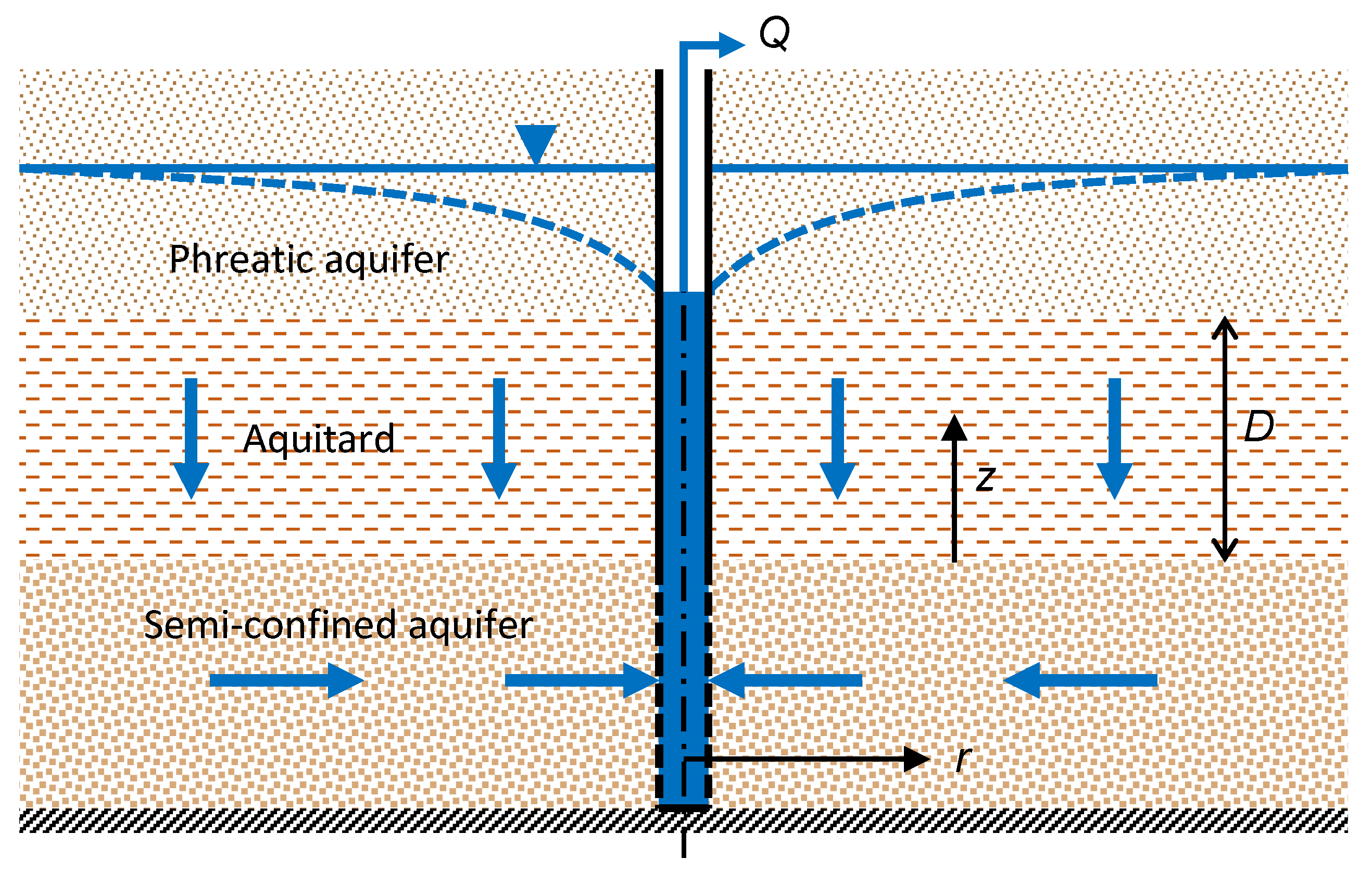
2.1. Theory
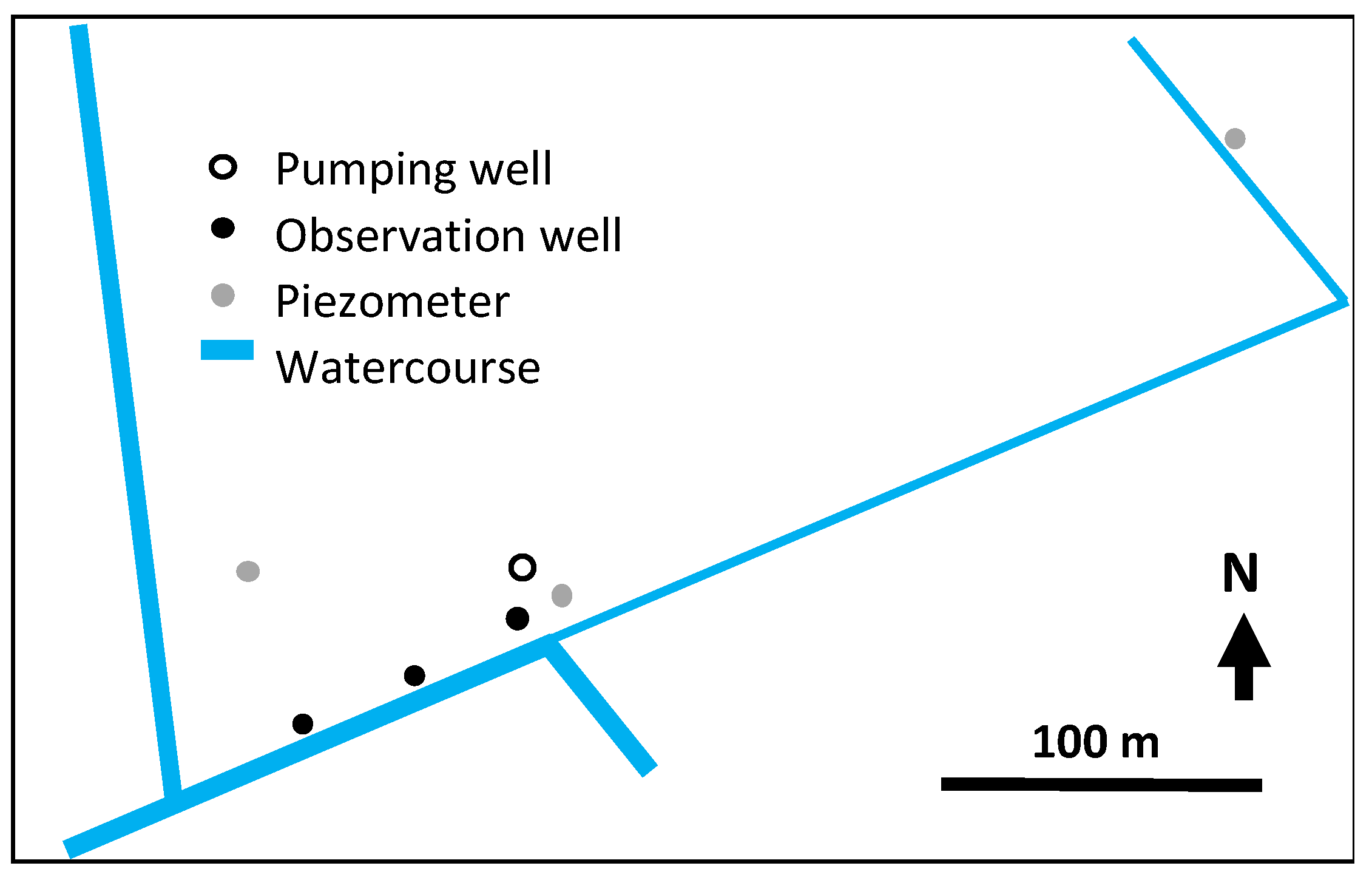
2.2. Test Case
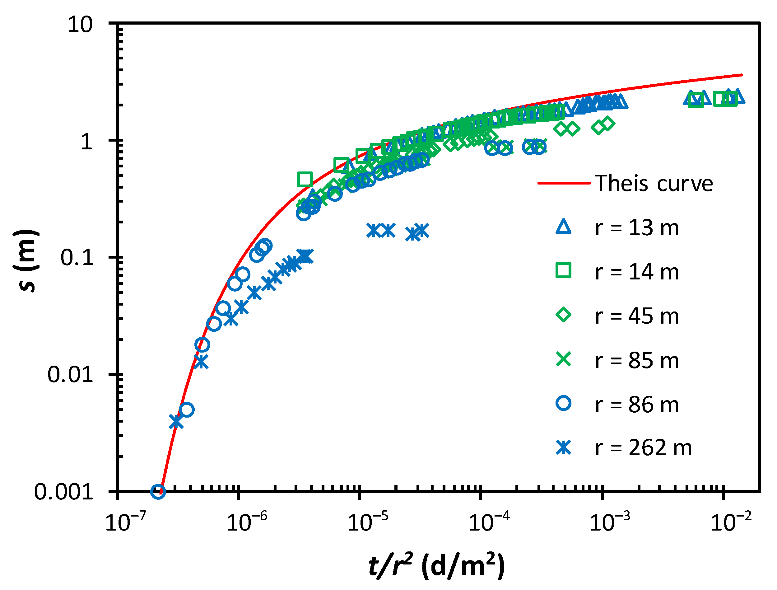
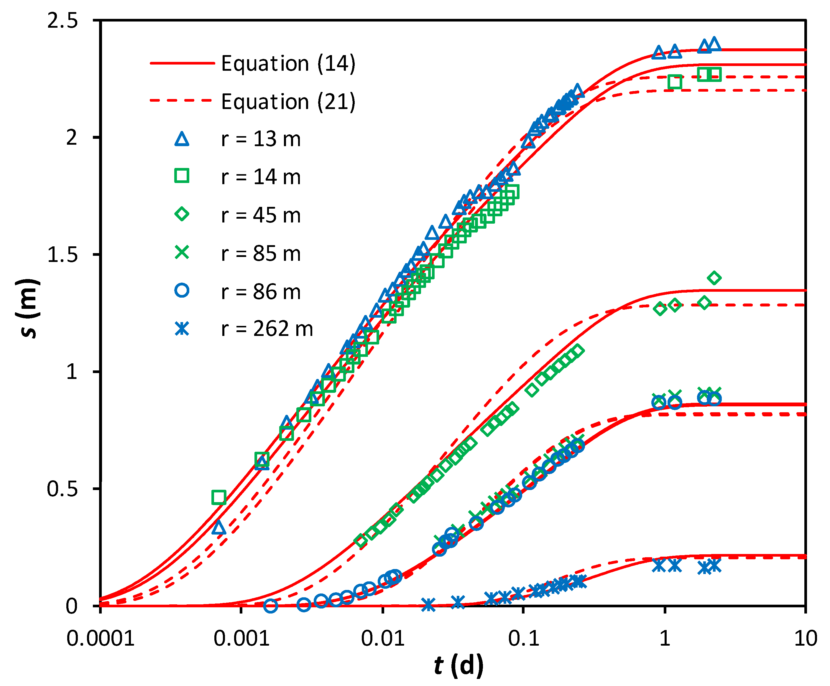
3. Results
4. Discussion
5. Conclusions
Funding
Conflicts of Interest
References
- Alley, W.M.; Healy, R.W.; Labaugh, J.W.; Reilly, T.E. Flow and storage in groundwater systems. Science 2002, 296, 1985–1990. [Google Scholar] [CrossRef] [PubMed]
- Van der Kamp, G. Methods for determining the in situ hydraulic conductivity of shallow aquitards—An overview. Hydrogeol. J. 2001, 9, 5–16. [Google Scholar] [CrossRef]
- Burbey, T.J. Use of time-subsidence data during pumping to characterize specific storage and hydraulic conductivity of semi-confining units. J. Hydrol. 2003, 281, 3–22. [Google Scholar] [CrossRef]
- Zhuang, C.; Zhou, Z.; Zhan, H.; Wang, G. A new type curve method for estimating aquitard hydraulic parameters in a multi-layered aquifer system. J. Hydrol. 2015, 527, 212–220. [Google Scholar] [CrossRef]
- Hart, D.J.; Bradbury, K.R.; Feinstein, D.T. The vertical hydraulic conductivity of an aquitard at two spatial scales. Groundwater 2006, 44, 201–211. [Google Scholar] [CrossRef] [PubMed]
- Konikow, L.F.; Neuzil, C.E. 2007. A method to estimate groundwater depletion from confining layers. Water Resour. Res. 2007, 43, W07417. [Google Scholar] [CrossRef]
- Smith, L.A.; van der Kamp, G.; Hendry, M.J. A new technique for obtaining high-resolution pore pressure records in thick claystone aquitards and its use to determine in situ compressibility. Water Resour. Res. 2013, 49, 732–743. [Google Scholar] [CrossRef]
- Hantush, M.S.; Jacob, C.E. Non-steady radial flow in an infinite leaky aquifer. Trans. Am. Geophys. Union 1955, 36, 95–100. [Google Scholar] [CrossRef]
- Hantush, M.S. Modification of the theory of leaky aquifers. J. Geophys. Res. 1960, 65, 3713–3725. [Google Scholar] [CrossRef]
- Neuman, S.P.; Witherspoon, P.A. Field determination of the hydraulic properties of leaky multiple aquifer systems. Water Resour. Res. 1972, 8, 1284–1298. [Google Scholar] [CrossRef]
- De Smedt, F. Constant-rate pumping test in a leaky aquifer with water release from storage in the aquitard. Groundwater 2020, 58, 487–491. [Google Scholar] [CrossRef] [PubMed]
- Moench, A.F. Transient flow to a large-diameter well in an aquifer with storative semiconfining layers. Water Resour. Res. 1985, 21, 1121–1131. [Google Scholar] [CrossRef]
- Feng, Q.; Zhan, H. On the aquitard–aquifer interface flow and the drawdown sensitivity with a partially penetrating pumping well in an anisotropic leaky confined aquifer. J. Hydrol. 2015, 521, 74–83. [Google Scholar] [CrossRef]
- Kruseman, G.P.; de Ridder, N.A. Analysis and Evaluation of Pumping Test Data, 2nd ed.; Publication 47; International Institute for Land Reclamation and Improvement: Wageningen, The Netherlands, 1994. [Google Scholar]
- Batu, V. Aquifer Hydraulics: A Comprehensive Guide to Hydrogeologic Data Analysis; John Wiley & Sons Inc.: New York, NJ, USA, 1998. [Google Scholar]
- Cheng, A.H.-D. Multilayered Aquifer Systems-Fundamentals and Applications; Marcel Dekker: New York, NY, USA; Basel, Switzerland, 2000. [Google Scholar]
- Walton, W.C. Aquifer Test Modelling; CRC Press: Boca Raton, FL, USA, 2007. [Google Scholar]
- Boonstra, H.; Soppe, R. Well hydraulics and aquifer tests. In Groundwater Engineering, 2nd ed.; Delleur, J.W., Ed.; CRC Press: Boca Raton, FL, USA, 2007; pp. 10-1–10-35. [Google Scholar]
- Sneddon, I.N. The Use of Integral Transforms; Tata McGraw-Hill Publ. Co. Ltd.: New Delhi, India, 1974; 539p. [Google Scholar]
- Davies, B.; Martin, B. Numerical inversion of the Laplace transform: A survey and comparison of methods. J. Comput. Phys. 1979, 33, 1–32. [Google Scholar] [CrossRef]
- Theis, C.V. The relation between the lowering of the piezometric surface and the rate and duration of discharge of a well using groundwater storage. Trans. Am. Geophys. Union 1935, 16, 519–524. [Google Scholar] [CrossRef]
- IMSL Numerical Libraries. Available online: https://www.imsl.com/ (accessed on 9 March 2023).
- Yeh, H.D.; Huan, Y.C. Parameter estimation for leaky aquifers using the extended Kalman filter, and considering model and data measurement uncertainties. J. Hydrol. 2005, 302, 28–45. [Google Scholar] [CrossRef]
- Rushton, K.R. Impact of aquitard storage on leaky aquifer pumping test analysis. Q. J. Eng. Geol. Hydrogeol. 2005, 38, 325–336. [Google Scholar] [CrossRef]
- Akaike, H. A new look at the statistical model identification. IEEE Trans. Autom. Control 1974, 19, 716–723. [Google Scholar] [CrossRef]
- Burnham, K.P.; Anderson, D.R. Multimodel inference: Understanding AIC and BIC in model selection. Sociol. Method. Res. 2004, 33, 261–304. [Google Scholar] [CrossRef]

| Parameter | Units | Equation (14) | Equation (21) |
|---|---|---|---|
| T | m2/d | 71.6 ± 0.9 | 75.1 ± 1.8 |
| S | 10−4 | 2.73 ± 0.16 | 4.75 ± 0.29 |
| C | 10−3 d−1 | 1.96 ± 0.11 | 2.07 ± 0.22 |
| S’ | 10−4 | 15.4 ± 1.6 | 0 |
| DF | - | 171 | 172 |
| RSS | m2 | 0.203 | 0.862 |
| RSE | m | 0.034 | 0.071 |
| AIC | - | −676 | −425 |
| BIC | - | −660 | −412 |
Disclaimer/Publisher’s Note: The statements, opinions and data contained in all publications are solely those of the individual author(s) and contributor(s) and not of MDPI and/or the editor(s). MDPI and/or the editor(s) disclaim responsibility for any injury to people or property resulting from any ideas, methods, instructions or products referred to in the content. |
© 2023 by the author. Licensee MDPI, Basel, Switzerland. This article is an open access article distributed under the terms and conditions of the Creative Commons Attribution (CC BY) license (https://creativecommons.org/licenses/by/4.0/).
Share and Cite
De Smedt, F. Determination of Aquitard Storage from Pumping Tests in Leaky Aquifers. Water 2023, 15, 3735. https://doi.org/10.3390/w15213735
De Smedt F. Determination of Aquitard Storage from Pumping Tests in Leaky Aquifers. Water. 2023; 15(21):3735. https://doi.org/10.3390/w15213735
Chicago/Turabian StyleDe Smedt, Florimond. 2023. "Determination of Aquitard Storage from Pumping Tests in Leaky Aquifers" Water 15, no. 21: 3735. https://doi.org/10.3390/w15213735
APA StyleDe Smedt, F. (2023). Determination of Aquitard Storage from Pumping Tests in Leaky Aquifers. Water, 15(21), 3735. https://doi.org/10.3390/w15213735