Article

Soil Hydraulic Properties Estimated from Evaporation Experiment Monitored by Low-Cost Sensors

by
Tallys Henrique Bonfim-Silva
1,*,
Everton Alves Rodrigues Pinheiro
2,*,
Tonny José Araújo da Silva
1,
Thiago Franco Duarte
1,
Luana Aparecida Menegaz Meneghetti
1 and
Edna Maria Bonfim-Silva
1
1
Institute of Agricultural and Technological Sciences, Federal University of Rondonópolis, Rondonópolis 78735-901, MT, Brazil
2
Federal University of Tocantins, Gurupi 77410-530, TO, Brazil
*
Authors to whom correspondence should be addressed.
Agronomy 2025, 15(8), 2009; https://doi.org/10.3390/agronomy15082009
Submission received: 8 July 2025 / Revised: 8 August 2025 / Accepted: 18 August 2025 / Published: 21 August 2025

Abstract

The estimation of soil hydraulic properties—such as water retention and hydraulic conductivity—is essential for irrigation management and agro-hydrological modeling. This study presents the development and application of SOILHP, a low-cost, IoT-integrated device designed to monitor laboratory evaporation experiments for the estimation of soil hydraulic properties using inverse modeling tools. SOILHP incorporates mini-tensiometers, a precision balance, microcontrollers, and cloud-based data logging via Google Sheets. SOILHP enables the remote, real-time acquisition of soil pressure head and mass variation data without the need for commercial dataloggers. Evaporation experiments were conducted using undisturbed soil samples, and inverse modeling with Hydrus-1D was used to estimate van Genuchten–Mualem parameters. The optimized parameters showed low standard errors and narrow 95% confidence intervals, demonstrating the robustness of the inverse solution, confirming the device’s sensors accuracy. Forward simulations of internal drainage were performed to estimate the field capacity under different drainage flux criteria. The field capacity results aligned with values reported in the literature for tropical soils. Overall, SOILHP proved to be a reliable and economically accessible alternative for monitoring evaporation experiments aimed at fitting parameters of analytical functions that describe water retention and hydraulic conductivity properties within the soil pressure head range relevant to agriculture.

1. Introduction

Quantifying soil water flow in the vadose zone is essential for efficient irrigation management and soil conservation, supporting both food security and environmental sustainability [1]. Precision agriculture aims to optimize the use of agricultural inputs, reduce costs, and minimize losses [2]. However, for this technique to be successfully applied in soil water management, accurately estimating soil hydraulic properties, such as water retention θ(h) and hydraulic conductivity K(h), is essential. Knowledge of these hydraulic properties is necessary for agro-hydrological modeling, which enables the simulation of crop yield under various scenarios, e.g., water stress conditions and different soil management practices [3]. They are also key for estimating the upper limit of soil water availability, known as field capacity, which is one of the most common agronomic metrics used in static approaches aiming to quantify soil water availability [4,5,6]. Field capacity is typically used as an irrigation threshold to avoid the application of excess water, which would otherwise be lost through deep percolation. Therefore, developing and improving methods that simplify the estimation of the analytical relationships θ(h) and K(h) is crucial for advancing modern agriculture.
Soil hydraulic properties can be estimated indirectly using pedotransfer functions [7] or directly, either in the field or in the laboratory, through transient flow experiments [8,9] or hydrostatic equilibrium methods [10]. Laboratory methods are the most commonly used, with θ(h) typically determined using devices such as tension tables and pressure chambers. For saturated hydraulic conductivity, constant or falling head permeameters are used. However, these methods have limitations, such as the lack of hydrostatic equilibrium in the pressure chamber at low pressure heads, particularly in clay soils [11], and the inability to estimate hydraulic conductivity simultaneously with water retention.
Transient flow methods, such as evaporation experiments in laboratory conditions, offer greater accuracy and speed up the estimation of soil hydraulic properties. The use of evaporation experiments with soil samples was first introduced by [12] and has since undergone several modifications (e.g., [8,9,13]). Various laboratory devices have been successfully used to monitor these evaporation experiments. Through such experiments, it is possible to generate both water retention and unsaturated hydraulic conductivity functions by tracking temporal changes in pressure head and evaporation rate in soil samples. The evaporation method allows for the simultaneous determination of water retention and hydraulic conductivity within the soil pressure head range relevant to agriculture (pressure heads from 0 to around −800 cm). However, the commercial sensors and software used to monitor these experiments are relatively expensive, which limits the adoption of this method by some soil physics laboratories located in regions with limited research funding.
The use of sensors integrated with the Internet of Things (IoT) is becoming increasingly common in agriculture, with a growing number of studies applying cloud platforms to facilitate data storage and processing. This technique enhances the efficiency of automating both field and laboratory experiments [14,15]. In this study, we aimed to develop and test a low-cost device, managed by a microcontroller integrated with the IoT, capable of remotely and continuously monitoring pressure heads within a soil sample and its mass variation during an evaporation experiment under laboratory conditions, with the goal of determining its hydraulic properties [θ(h) and K(h)].

2. Materials and Methods

2.1. Sensor Selection and Assembly of the SOILHP Device

The device for monitoring soil sample evaporation experiments, hereafter referred to as SOILHP, was developed between June 2023 and June 2024 at the Instrumentation Laboratory of the Cerrado Research Center (NuPeC) at the Federal University of Rondonópolis (UFR), Mato Grosso, Brazil. In evaporation experiments aimed at determining soil hydraulic properties, the key state variables measured are the soil pressure head (or soil water content) and the temporal change in the mass of an initially saturated soil sample. For this study, mini-tensiometers were built to record changes in pressure head, and a precision balance was assembled to measure changes in the soil sample mass. The temporal variation in soil mass allowed for the calculation of the evaporation rate, which served as the upper boundary condition for the subsequent inverse modeling procedure to determine the soil hydraulic properties.
The selected sensors have low uncertainty levels and an affordable cost. The total price of the final version of the SOILHP device shown in Figure 1C—including the mini-tensiometers—was approximately USD 250. Under controlled laboratory conditions, all components of the SOILHP device were tested. Among the available microcontroller options for the SOILHP processing module, the Arduino UNO R3 was selected. The SOILHP device was assembled based on the selection of the necessary components that make up the transmitter module (ESP8266 + logic level converter), processing module (Arduino UNO R3 + shield), ADC module (24-bit AD1256), and power supply. To receive data from the processing module and handle transmission and cloud storage, the ESP8266 board (NodeMCU model) was used.
The SOILHP mini-tensiometers were built using commercially available porous cups with an air-entry value of approximately −85 kPa, measuring 10 mm in outer diameter and 35 mm in height. Each mini-tensiometer body was made using a transparent plastic tube, which was sealed to the porous cup using sealing adhesive. To measure the pressure head, the mini-tensiometers were coupled with piezoresistive pressure transducers from the MPX5100DP series, a high-precision (maximum variation of 2.5% relative to the measured value) monolithic silicon sensor. The pressure transducer signals were sent to an ADC converter. The connection between the sensor and the mini-tensiometer was made using flexible silicone tubing, 40 mm in length and 4 mm in outer diameter. Although the pressure sensor connected to the mini-tensiometer offered good accuracy, an independent calibration was performed in this study using a mercury manometer connected to a vacuum pump.
To build the precision balance of the SOILHP device, a single-point load cell with a maximum capacity of 2000 g was used. The load data were transmitted via a JY-S60 load transmitter (CALT, Shanghai, China) to the ADC converter.
To ensure proper sensor operation under the conditions required for this study, a key component for digital signal processing was the analog-to-digital converter (ADC), model AD1256, 24-bit, from Texas Instruments. This converter played a crucial role in converting low-noise analog signals from the sensors into digital format, enabling their use by the Arduino UNO R3 microcontroller (Arduino AG, Turin, Italy).
The final version of the SOILHP device, shown in Figure 1, also includes an external structure to protect the components. The structure was designed using Autodesk Inventor Professional 2024, a widely used software for 3D projects. The structural drawings were divided into parts for 3D printing using additive manufacturing, carried out with a Creality Ender Dragon Pro printer (Creality 3D Technology Co., Ltd., Shenzhen, China) and polylactic acid (PLA) filament. The base platform of the SOILHP device was built from a 190 × 260 mm steel plate, 10 mm thick. The entire electrical circuit, along with the sensors and 3D-printed protective housing, was assembled on this platform.

2.2. Algorithms

The algorithm for reading pressure head and soil mass was developed in the integrated development environment (IDE) using C/C++ language, with Arduino UNO R3 serving as the microcontroller hardware. A separate code was also written for ESP8266, enabling it to receive data from Arduino UNO R3 and send it to Google Sheets in the cloud every 10 min. The libraries used on Arduino UNO R3 were ADS1256.h, SPI.h, and SoftwareSerial.h, based on Texas Instruments’ example algorithm “Efficient Input Cycling”. For ESP8266, the ESP8266WiFi.h and WiFiClientSecure.h libraries were utilized to enable the reception of data from Arduino and its transmission to the cloud.

2.3. Sensor Calibration

The calibration of the SOILHP balance was carried out after assembling the external protective structure for the circuits, using a calibration algorithm. Standard weights were used for calibration, and a hysteresis analysis of the load cell was also performed, involving loading from 0 g to 2000 g to generate a loading equation, followed by unloading from 2000 g back to 0 g.
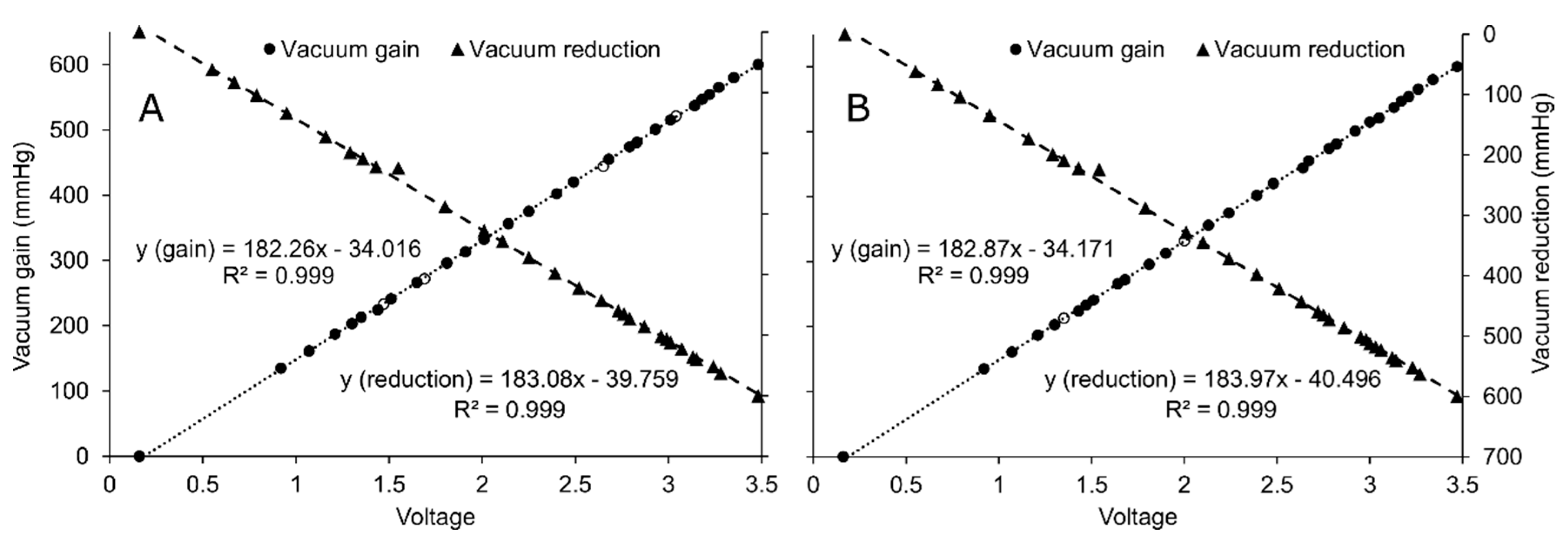
For the calibration of the MPX5100DP vacuum sensor (NXP Semiconductors N.V., Eindhoven, The Netherlands), a mercury manometer was used in combination with a vacuum pump in a closed-circuit system. After connecting the sensors to the circuit, the vacuum was gradually increased from 0 mmHg to 600 mmHg. During this process, 30 voltage readings (V) were collected from the sensors, each corresponding to different vacuum levels (mmHg). Subsequently, the reverse process was carried out, decreasing the vacuum from 600 mmHg back to 0 mmHg. From these pairs of data (voltage vs. vacuum), calibration equations were derived.

2.4. Soil Sampling for the Evaporation Experiment

Soil sampling for the tests was carried out in the experimental area of UFR, municipality of Rondonópolis, Mato Grosso, Brazil. The sampling site has been cultivated with cotton for the past five years using conventional tillage. The sampled soil is a Latossolo Vermelho distrófico according to the Brazilian system of soil classification [16], equivalent to an Oxisol in the soil taxonomy classification [17]. Particle size distribution, textural classes, and bulk density of the sampled soil layers are presented in Table 1.
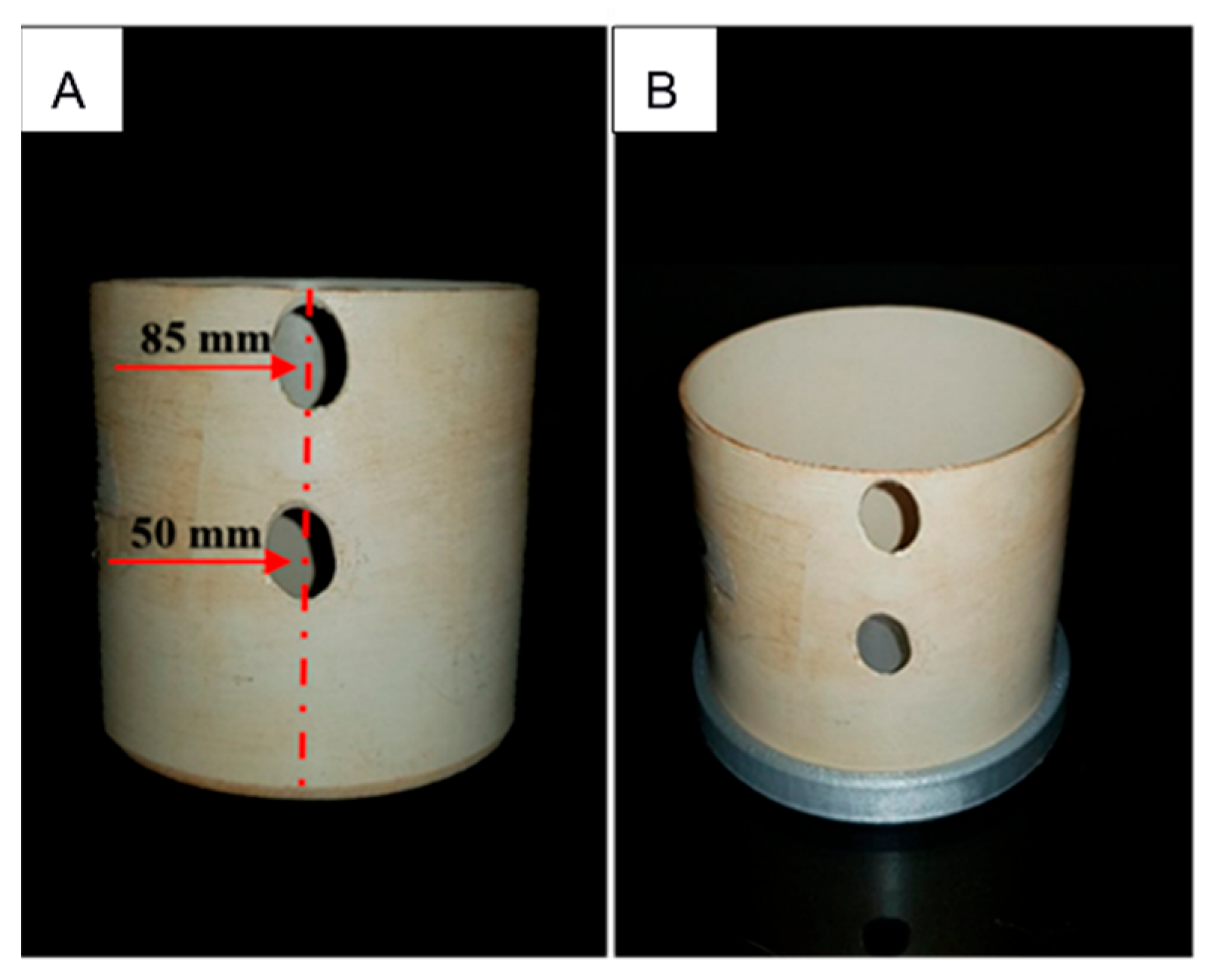
For undisturbed soil sampling, volumetric cylinders were prepared using PVC tubing with a diameter of 10 cm and a height of 10 cm (785.4 cm3). Two lateral holes, each 1.2 cm in diameter, were drilled at heights of 5 cm and 8.5 cm from the base of the cylinder to allow for the insertion of the tensiometers (Figure 2). Undisturbed samples were taken from three soil depths: 0–20 cm, 20–40 cm, and 40–60 cm.
After sampling the soil layers and sample preparation in the laboratory, a PLA cap with four holes was fitted to the base of the soil-filled cylinder (Figure 2B). The soil samples were then saturated slowly by capillarity over a period of 72 h. Once saturation was complete, the holes in the base cap were properly sealed, and two mini-tensiometers were inserted through the holes in the cylinder. To minimize sample deformation during this procedure, a punch guided by a 35°-angled template in relation to the cylinder wall was used. This angle allowed the center of the porous cups to align with the center of the cylinder at depths of 3.1 cm for the upper mini-tensiometer and 7.1 cm for the lower mini-tensiometer, measured from the top surface of the soil sample.
The soil sample with the tensiometers was placed on the balance, and the tensiometers were connected to the vacuum sensors. A fan system was mounted to enhance evaporation. Data on the mass variation of the sample—measured by the load cell—and the pressure head—measured by the upper and lower mini-tensiometers—were recorded every 10 min and transmitted to the cloud via the ESP8266 board, being stored in a spreadsheet of Google Sheets (Table 2). This method of data transmission and storage eliminated the need for a “physical datalogger” and enabled real-time remote access to the experimental data. The evaporation experiment was concluded when the lower tensiometer stopped providing readings, at tensions around 800 cm, which occurred after approximately four days. The first three readings were discarded, as the initial 30 min were required for the measurements to stabilize (Table 2).

2.5. Inverse Modeling with Hydrus-1D

At the end of the evaporation experiment, the sensors were disconnected from the soil sample, which was dried at 105 °C for 24 h to determine the dry weight and the soil water content throughout the experiment. The evaporation rate [E (cm h−1)] of water from the soil sample for each time interval was calculated based on the change in mass [Δm (g)], the time interval [Δt (h)], the density of water [ρa (g cm−3)], and the surface area of the cylinder [A (cm2)], according to
E = m t · A   ·   ρ a  
Among the most commonly used equations to represent the soil hydraulic properties of water retention θ(h) and hydraulic conductivity K(h) are the equations of Mualem (1976) and van Genuchten (1980) [18,19], hereafter referred to as VGM:
Θ = [   1 +   α h n ] ( 1 / n )     1
K = K s Θ l [ 1 ( 1 Θ n / ( n 1 ) ) 1 ( 1 / n ) ] 2
In these equations, Θ = (θθr)/(θsθr) is the effective saturation, θ [cm3 cm−3] is the soil water content, h (cm) is the pressure head, and K (cm h−1) is the soil hydraulic conductivity. Six parameters define the soil hydraulic properties, commonly referred to as the VGM parameters: θr (residual soil water content), θs (soil water content at saturation), Ks (saturated hydraulic conductivity), and the shape parameters α [cm−1], n [-], and l [-].
The Hydrus-1D model [20] includes an inverse solution module that enables the simultaneous optimization of the VGM parameters of Equations (2) and (3) using transient flow experiments, such as evaporation experiments [8,20]. This is achieved by minimizing an objective function through the Marquardt–Levenberg algorithm [21], while aiming to reproduce the measured pressure and/or soil water content data using the numerical solution of the Richards equation (Equation (4)).
d θ d t = d d z K h d h d z + 1
where θ is the soil water content [cm3 cm−3], t is time [h], K(h) is the unsaturated hydraulic conductivity [cm h−1], h is pressure [cm], and z is the vertical coordinate [cm].
For the inverse solution of the evaporation experiments in this study, a zero-flow boundary condition was applied at the base of the soil sample, and the measured evaporation rate was defined as the upper boundary condition. The data used for the inverse solution included two observations of the average soil water content of the entire sample during the evaporation experiment—one at the beginning and one at the end of the experiment—as well as pressure head measurements throughout the experiment at the two predefined positions within the soil sample, totaling an average of 700 observation points for the objective function.

2.6. Application Example: Forward Simulation for Estimating the Field Capacity

Based on the soil hydraulic properties obtained through inverse modeling in the evaporation experiments monitored by the SOILHP device, a forward simulation of an internal drainage experiment (lasting 60 days) was conducted to estimate soil water content and pressure head at field capacity. The simulated scenario included a 1 m deep soil profile, using hydraulic properties from the three analyzed layers: 0–20 cm, 20–40 cm, and 40–100 cm. Below 60 cm, the sampled soil was homogenous; therefore, the VGM parameters from 40 to 60 cm were extrapolated to those of the 60–100 cm layer. The upper boundary condition of this simulation was set as zero flux, while the lower boundary condition was set as free drainage at the bottom of the profile. The initial condition assumed a nearly saturated soil profile, with a uniform pressure head of −0.1 cm. Different flux densities for the definition of field capacity were tested at a depth of 0.6 m, i.e., 1 mm d−1, 2 mm d−1, and 4 mm d−1—reasonable thresholds commonly used to define the field capacity in most soils [22,23,24].

3. Results and Discussion

3.1. Calibration and Sensor Test

The MPX5100DP vacuum sensor calibration resulted in a linear response of the sensor signal during both the vacuum increase and the vacuum release phases (Figure 3). The calibration equation related to the vacuum increase was used, since in laboratory evaporation experiments, the vacuum in the tensiometer cup consistently rises as the soil dries. As seen in Figure 3, the two MPX5100DP sensors used in the SOILHP device produced nearly identical calibration equations (RMSE = 0.0084 mmHg), confirming the stability of the signal from this low-cost sensor. Other authors have also demonstrated the feasibility of using this sensor to measure the soil pressure head [25].
Regarding the load cell, after assembling the balance structure in the final version of the SOILHP device (Figure 1C), a hysteresis test was performed by recording the response during both the loading and the unloading phases of the weighing system. The results showed that the maximum difference observed in the hysteresis test was smaller than 0.3% (Table 3). This type of calibration for weighing systems is important to minimize systematic errors that may arise during the device operational period [26].

3.2. Optimization of the Hydraulic Parameters for a Soil Profile

Based on the evaporation experiment conducted for three layers of soil profile, inverse modeling using the Hydrus-1D model yielded a set of VGM parameters that satisfactorily represented the pressure head values measured by the mini-tensiometers during the experiment. The model consistently converged to the same final set of soil hydraulic parameters, regardless of the initial estimates of the VGM parameters. Figure 4 presents the observed and estimated pressure head values from the inverse solution at both measurement positions within the soil samples for all three soil layers, along with the corresponding RMSE values.
In Figure 5, it can be observed that for the sampled soil and under the laboratory’s atmospheric conditions, evaporation during the first 30 h of the experiment was limited by the atmosphere just above the soil sample. After the 30-h mark, a more pronounced reduction in the evaporation rate was observed, indicating that from that point onward, evaporation became source-limited. A similar behavior was reported by [27] in studies on the evaporation method under laboratory conditions.
The average values of the VGM parameters obtained through inverse modeling with Hydrus-1D, along with their respective statistics, are presented in Table 4.
The results obtained through inverse modeling with Hydrus-1D for each analyzed soil layer (Table 4) showed a low standard error and narrow 95% confidence intervals. Using the VGM parameter correlations and standard error results from Hydrus-1D inverse solution for the first soil layer in Table 4, Figure 6 presents the correlation matrix from 1000 stochastic realizations generated through multivariate random sampling using Cholesky decomposition [28]. The correlation matrix and Pearson correlations between the VGM parameters were the same as those produced by the inverse solution in Hydrus-1D. As shown in Table 4 and in Figure 6, the VGM parameters exhibited low dispersion, indicating that the estimation of the θ(h) and K(h) properties using SOILHP led to minimal uncertainty propagation [28]. These findings confirmed the robustness of the results derived from the evaporation experiments monitored using the SOILHP device.
Based on the optimized parameters from Table 4, Figure 7A shows the water retention curves, and Figure 7B presents the hydraulic conductivity curves according to the van Genuchten–Mualem equations (Equations (2) and (3)) for the three sampled soil layers.
The behavior of the θ(h) function for the 20–40 cm and 40–60 cm soil layers was similar (Figure 7A). In contrast, the surface layer (0–20 cm) showed a slightly different θ(h) function, with lower water content as the soil dried, likely due to reduced microporosity (aggregate breakdown) caused by repeated conventional tillage operations in the sampling area. Regarding the K(h) function, the 0–20 cm and 20–40 cm layers exhibited higher hydraulic conductivity values compared to the 40–60 cm layer; however, this difference tended to diminish as the soil became drier.

3.3. Field Capacity Simulation

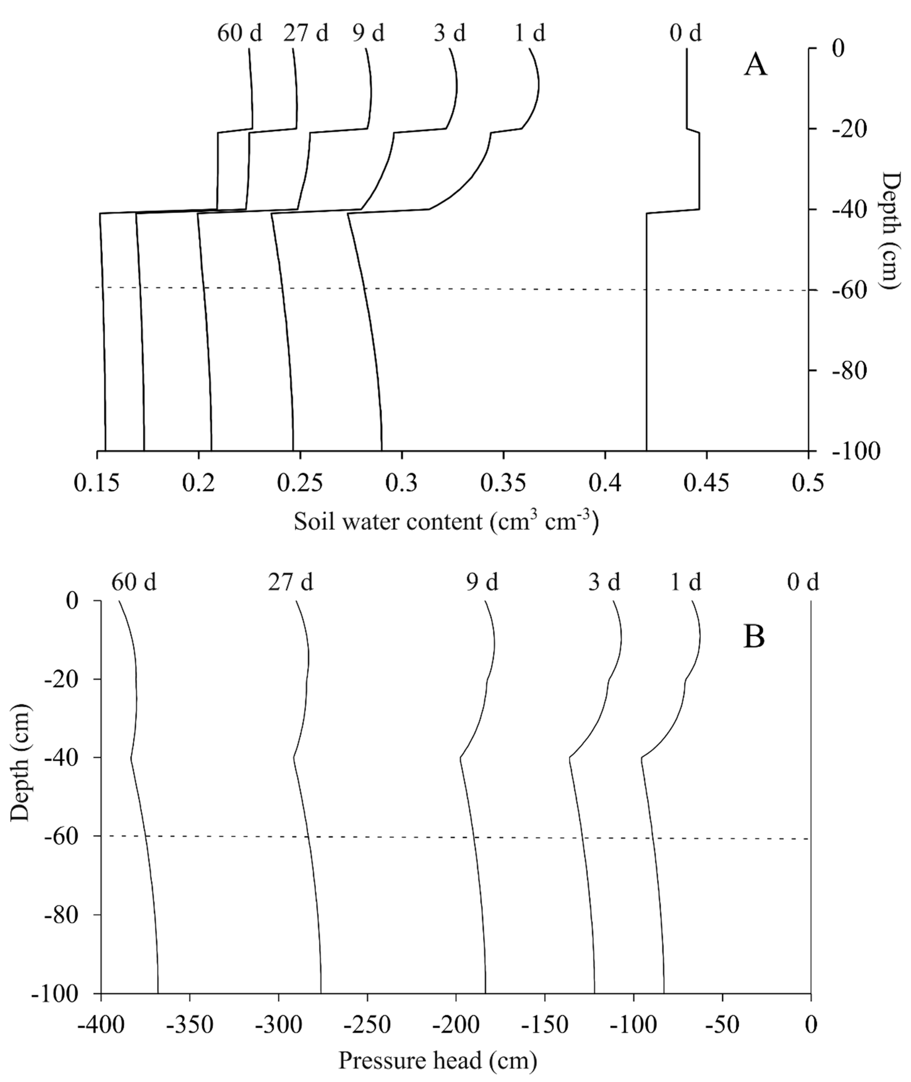
Figure 8 shows the water content and pressure head profiles from a forward simulation of an internal drainage experiment using the Hydrus-1D model, based on the hydraulic parameters from Table 4. The 0 d profiles (at the onset of the simulations) represent the initial condition. The profiles at five additional times are shown, i.e., 1 day, 3 days, 9 days, 27 days, and 60 days after the onset. The most pronounced changes in water content occurred in the first few days, when hydraulic conductivity was high, and water flow was faster than in the later stages of the experiment—a behavior similarly reported by [4].
Table 5 shows the number of days required to reach field capacity, along with the corresponding average values of pressure head and water content, for three different flux density thresholds at a depth of 60 cm. When the target flux density was reached at the predefined depth, the average pressure head and water content from the surface to that depth (60 cm) were used to define the field capacity.
The results presented in Table 5 are consistent with the sampled soil and with values reported in the literature for Brazilian soils [4,22]. For tropical soils, qfc values lower than 1 mm d−1 often require an impractically long time to be reached [29]. It was observed that a qfc of 4 mm d−1 resulted in a feasible experiment duration and produced ψfc values close to those commonly reported in the literature for Brazilian soils [24].
These internal drainage simulation results demonstrate that the SOILHP device is capable of effectively monitoring evaporation experiments, providing the necessary data for accurate inverse modeling and successful optimization of VGM parameters that represent water retention and hydraulic conductivity properties.

4. Conclusions

The SOILHP device developed in this study, equipped with low-cost sensors and microcontrollers, was capable of monitoring remotely and in real time evaporation experiments using Internet of Things (IoT) technology.
The hydraulic parameters optimized through inverse modeling with Hydrus-1D, based on the state variables measured by the SOILHP device during the evaporation experiments, showed narrow 95% confidence intervals and low standard errors. This indicates that the optimization process converged to a local minimum of the objective function, minimizing the propagation of uncertainty in the soil hydraulic parameters when used in agro-hydrological simulations.
Internal drainage simulations using the hydraulic parameters optimized from SOILHP data produced field capacity estimates consistent with values reported in the literature for similar Brazilian soils.
The SOILHP device developed in this research, combined with the inverse modeling capabilities of Hydrus-1D, proved to be a cost-effective alternative to commercial systems for monitoring evaporation experiments and optimizing soil hydraulic parameters.

Author Contributions

Conceptualization, E.A.R.P., T.J.A.d.S. and T.H.B.-S.; methodology, E.A.R.P. and T.H.B.-S.; software, T.H.B.-S.; validation, E.A.R.P. and T.H.B.-S.; resources, E.A.R.P., T.J.A.d.S., T.H.B.-S., E.M.B.-S., L.A.M.M. and T.F.D.; data curation, T.H.B.-S. and L.A.M.M.; writing—original draft preparation, T.H.B.-S., E.A.R.P. and T.J.A.d.S.; writing—review and editing, E.A.R.P.; visualization, E.M.B.-S., L.A.M.M. and T.F.D.; supervision, E.A.R.P. and T.J.A.d.S. All authors have read and agreed to the published version of the manuscript.

Funding

This research received no external funding.

Data Availability Statement

All the data reported here are available from the authors upon request.

Acknowledgments

The authors would like to thank CAPES (Coordination for the Improvement of Higher Education Personnel) for providing financial support through a scholarship.

Conflicts of Interest

The authors declare no conflicts of interest. The funders had no role in the design of the study; in the collection, analyses, or interpretation of data; in the writing of the manuscript; or in the decision to publish the results.

References

  1. Vogel, M.M.; Orth, R.; Cheruy, F.; Hagemann, S.; Lorenz, R.; Hurk, B.J.J.M.; Seneviratne, S.I. Regional amplification of projected changes in extreme temperatures strongly controlled by soil moisture-temperature feedbacks. Geophys. Res. Lett. 2017, 44, 1511–1519. [Google Scholar] [CrossRef]
  2. Barbosa Júnior, M.R.; de Almeida Moreira, B.R.; dos Santos Carreira, V.; de Brito Filho, A.L.; Trentin, C.; de Souza, F.L.P.; Tedesco, D.; Setiyono, T.; Flores, J.R.; Ampatzidis, Y.; et al. Precision agriculture in the United States: A comprehensive meta-review inspiring further research, innovation, and adoption. Comput. Electron. Agric. 2024, 221, 108993. [Google Scholar]
  3. Bonfante, A.; Sellami, M.H.; Abi Saab, M.T.; Albrizio, R.; Basile, A.; Fahed, S.; Giorio, P.; Langella, G.; Monaco, E.; Bouma, J. The role of soils in the analysis of potential agricultural production: A case study in Lebanon. Agric. Syst. 2017, 156, 67–75. [Google Scholar] [CrossRef]
  4. de Jong van Lier, Q.; Wendroth, O. Reexamination of the Field Capacity Concept in a Brazilian Oxisol. Soil Sci. Soc. Am. J. 2016, 80, 264–274. [Google Scholar] [CrossRef]
  5. Romano, N.; Palladino, M.; Chirico, G.B. Parameterization of a bucket model for soil-vegetation-atmosphere modeling under seasonal climatic regimes. Hydrol. Earth Syst. Sci. 2011, 15, 3877–3893. [Google Scholar] [CrossRef]
  6. Twarakavi, N.K.C.; Sakai, M.; Šimůnek, J. An objective analysis of the dynamic nature of field capacity. Water Resour. Res. 2009, 45. [Google Scholar] [CrossRef]
  7. Vereecken, H.; Weynants, M.; Javaux, M.; Pachepsky, Y.; Schaap, M.G.; van Genuchten, M.T. Using Pedotransfer Functions to Estimate the van Genuchten–Mualem Soil Hydraulic Properties: A Review. Vadose Zone J. 2010, 9, 795–820. [Google Scholar] [CrossRef]
  8. Šimůnek, J.; van Genuchten, M.T.H.; Wendroth, O. Parameter Estimation Analysis of the Evaporation Method for Determining Soil Hydraulic Properties. Soil Sci. Soc. Am. J. 1998, 62, 894–905. [Google Scholar] [CrossRef]
  9. Wendroth, O.; Ehlers, W.; Hopmans, J.W.; Kage, H.; Halbertsma, J.; Wösten, J.H.M. Reevaluation of the Evaporation Method for Determining Hydraulic Functions in Unsaturated Soils. Soil Sci. Soc. Am. J. 1993, 57, 1436–1443. [Google Scholar] [CrossRef]
  10. Dane, J.H.; Hopmans, J.W. 3.3.2 Laboratory. In Methods of Soil Analysis; John Wiley & Sons, Ltd.: Hoboken, NJ, USA, 2002; pp. 675–720. Available online: https://acsess.onlinelibrary.wiley.com/doi/abs/10.2136/sssabookser5.4.c25 (accessed on 15 June 2024).
  11. Bittelli, M.; Flury, M. Errors in Water Retention Curves Determined with Pressure Plates. Soil Sci. Soc. Am. J. 2009, 73, 1453–1460. [Google Scholar] [CrossRef]
  12. Gardner, W.R.; Miklich, F.J. Unsaturated Conductivity and Diffusivity Measurements by a Constant Flux Method. Soil Sci. 1962, 93, 271–274. [Google Scholar] [CrossRef]
  13. Durner, W.; Iden, S.C. Extended multistep outflow method for the accurate determination of soil hydraulic properties near water saturation. Water Resour. Res. 2011, 47. [Google Scholar] [CrossRef]
  14. Comegna, A.; Hassan, S.B.M.; Coppola, A. Development and Application of an IoT-Based System for Soil Water Status Monitoring in a Soil Profile. Sensors 2024, 24, 2725. [Google Scholar] [CrossRef] [PubMed]
  15. Gomes Alves, R.; Filev Maia, R.; Lima, F. Discrete-event simulation of an irrigation system using Internet of Things. IEEE Lat. Am. Trans. 2022, 20, 941–947. [Google Scholar] [CrossRef]
  16. Dos Santos, H.G.; Jacomine, P.K.T.; dos Anjos, L.H.C.; Lumbreras, J.F.; de Oliveira, J.B.; de Oliveira, V.A.; Coelho, M.R.; de Almeida, J.A.; Cunha, T.J.F. Proposta de Atualização Da Segunda Edição Do Sistema Brasileiro de Classificação de Solos. 2009. Available online: http://www.infoteca.cnptia.embrapa.br/handle/doc/664470 (accessed on 30 March 2025).
  17. United States Department of Agriculture. Soil Taxonomy: A Basic System of Soil Classification for Making and Interpreting Soil Surveys, 2nd ed.; U.S. Department of Agriculture Handbook 436; Natural Resources Conservation Service: Washington, DC, USA, 1999. [Google Scholar]
  18. Mualem, Y. A new model for predicting the hydraulic conductivity of unsaturated porous media. Water Resour Res. 1976, 12, 513–522. [Google Scholar] [CrossRef]
  19. van Genuchten, M.T. A Closed-form Equation for Predicting the Hydraulic Conductivity of Unsaturated Soils. Soil Sci. Soc. Am. J. 1980, 44, 892–898. [Google Scholar] [CrossRef]
  20. Šimůnek, J.; van Genuchten, M.T.H.; Šejna, M. Recent Developments and Applications of the HYDRUS Computer Software Packages. Vadose Zone J. 2016, 15, vzj2016.04. [Google Scholar] [CrossRef]
  21. Marquardt, D.W. An Algorithm for Least-Squares Estimation of Nonlinear Parameters. J. Soc. Ind. Appl. Math. 1963, 11, 431–441. [Google Scholar] [CrossRef]
  22. De van Jong Lier, Q. Field capacity, a valid upper limit of crop available water? Agric. Water Manag. 2017, 193, 214–220. [Google Scholar] [CrossRef]
  23. Reynolds, W.D. An analytic description of field capacity and its application in crop production. Geoderma 2018, 326, 56–67. [Google Scholar] [CrossRef]
  24. Turek, M.E.; de Jong van Lier, Q.; Armindo, R.A. Estimation and mapping of field capacity in Brazilian soils. Geoderma 2020, 376, 114557. [Google Scholar] [CrossRef]
  25. Sanches, A.C.; de Alves, C.O.; de Jesus, F.L.F.; Theodoro, F.L.; da Cruz, T.A.C.; Gomes, E.P. Low-cost and high-efficiency automated tensiometer for real-time irrigation monitoring. Rev. Bras. Eng. Agríc. Ambient. 2022, 26, 390–395. [Google Scholar] [CrossRef]
  26. Amaral, A.M.; Cabral Filho, F.R.; Vellame, L.M.; Teixeira, M.B.; Soares, F.A.L.; dos Santos, L.N.S. Uncertainty of weight measuring systems applied to weighing lysimeters. Comput. Electron. Agric. 2018, 145, 208–216. [Google Scholar] [CrossRef]
  27. Schindler, U.; Müller, L. Simplifying the evaporation method for quantifying soil hydraulic properties. J. Plant Nutr. Soil Sci. 2006, 169, 623–629. [Google Scholar] [CrossRef]
  28. Wesseling, J.; Kroes, J.; Oliveira, T.C.; Damiano, F. The impact of sensitivity and uncertainty of soil physical parameters on the terms of the water balance: Some case studies with default R packages. Part II: Theory, methods and case descriptions. Comput. Electron. Agric. 2020, 170, 105072. [Google Scholar] [CrossRef]
  29. Dos Brito, A.S.; Libardi, P.L.; Mota, J.C.A.; Moraes, S.O. Estimativa da capacidade de campo pela curva de retenção e pela densidade de fluxo da água. Rev. Bras. Ciênc. Solo. 2011, 35, 1939–1948. [Google Scholar] [CrossRef]
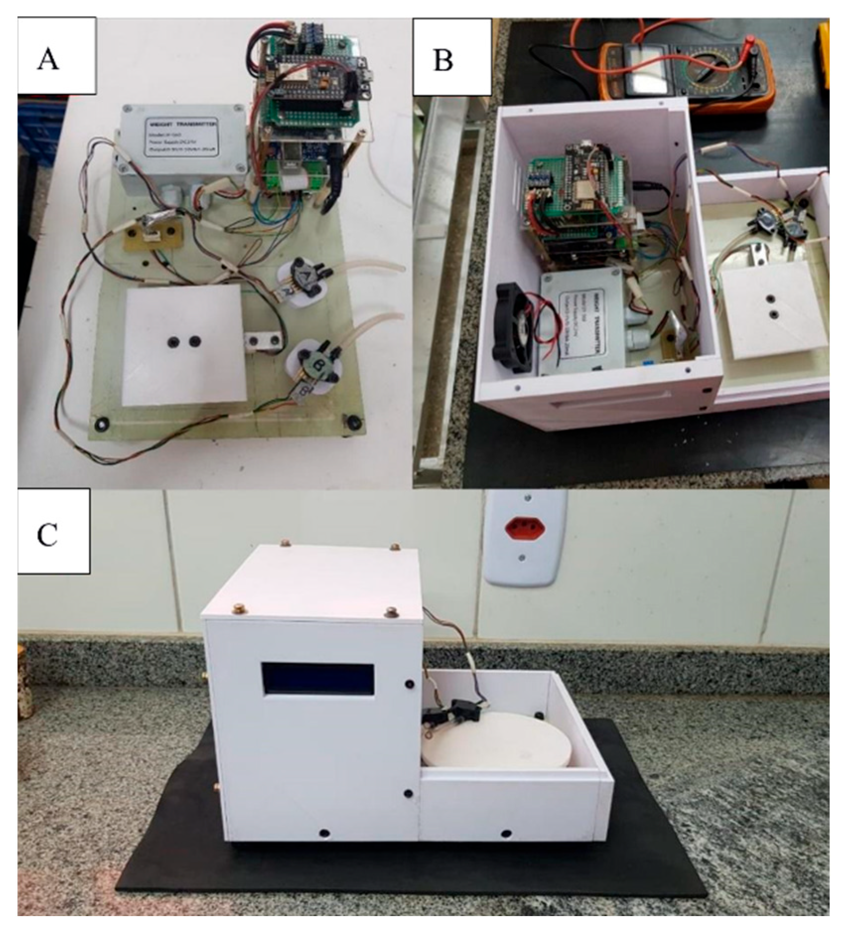
Figure 1. Assembled circuit without PLA structural housing (A); structural assembly of the device (B); final version of the SOILHP device (C).
Agronomy 15 02009 g001
Figure 2. Soil sampling cylinder. Side view of the cylinder showing the tensiometer insertion holes (A); cylinder with a PLA base cap (B).
Agronomy 15 02009 g002
Figure 3. Vacuum in mmHg as a function of electrical voltage (V) recorded at each observation point during the calibration of two MPX5100DP sensors (A,B).
Agronomy 15 02009 g003
Figure 4. Output of the Hydrus-1D model fit (solid lines) compared with the observed pressure head values during the evaporation experiment at the two monitored positions (black dots—upper mini-tensiometer; blue dots—lower mini-tensiometer) for each soil sample: 0–20 cm layer (A); 20–40 cm layer (B); and 40–60 cm layer (C).
Agronomy 15 02009 g004
Figure 5. Observed evaporation rate during the experiment for the sampled soil layers 0–20 cm (A), 20–40 cm (B), and 40–60 cm (C).
Agronomy 15 02009 g005
Figure 6. Scatterplot matrix for 1000 realizations of multivariate random sampling with Cholesky decomposition for evaporation experiments monitored by the SOILHP equipment. The diagonal shows the histograms, while the Pearson correlation together with its significance (p < 0.001) are displayed above the diagonal.
Agronomy 15 02009 g006
Figure 7. Water retention curve (A) and hydraulic conductivity curve (B) for the three analyzed soil layers.
Agronomy 15 02009 g007
Figure 8. Simulated profiles of water content (A) and pressure head (B) at different times (initial = day 0, and after 1, 3, 9, 27, and 60 days) using the hydraulic properties from Table 4. The dashed horizontal line represents the soil depth used for estimating the field capacity.
Agronomy 15 02009 g008
Table 1. Particle size distribution, soil bulk density, and USDA textural class of the sampled layers.
DepthSandSiltClayTextural ClassBulk Density
cm-----------------%-----------------g cm−3
0–2031.7317.3950.88Clay1.17
20–4028.0717.3954.55Clay1.22
40–6025.2920.5554.16Clay1.11
Table 2. Example of how data were recorded in a spreadsheet. Data extracted from the Google Sheets records. The red values indicate the first three readings that were discarded.
Date/TimeWeight (g)Upper Tensiometer (cm)Lower Tensiometer (cm)
4/13/2024 5:47:37 PM1538.80−20.09−29.47
4/13/2024 5:57:38 PM1546.24−20.09−29.47
4/13/2024 6:07:40 PM1544.2113.05−2.35
4/13/2024 6:17:41 PM1543.3519.783.57
4/13/2024 6:27:43 PM1542.4421.925.51
4/13/2024 6:37:45 PM1541.9122.646.12
4/13/2024 6:47:46 PM1540.9323.456.83
Table 3. Hysteresis test and difference between loading and unloading of mass (g) within the load cell supported limit.
ObservationLoadingUnloadingDifference (%)RMSE
-----g-----%g
10.000.000.001.94
2147.31147.630.22
3294.96295.670.24
4444.94445.570.14
5592.73593.870.19
6746.42747.730.18
7898.89900.700.20
81047.871049.620.17
91202.551205.010.20
101351.051351.40.03
111498.941502.620.25
121643.131645.680.16
131791.131793.790.15
141938.251941.840.19
152000.002000.000.00
Table 4. Hydraulic parameters of the van Genuchten–Mualem (VGM) equations optimized through inverse modeling with the Hydrus-1D model, along with their respective statistics, i.e., standard error and 95% confidence interval, based on data from evaporation experiments monitored by the SOILHP device.
VGMAverage ValueStandard Error95% Confidence Limits
0–20 cm
θr [cm3 cm−3]0.05810.00490.0485–0.0678
θs [cm3 cm−3]0.44010.01330.4140–0.4663
α [cm−1]0.01590.00080.0143–0.0175
n [–]1.44360.03041.3840–1.5032
Ks [cm h−1]0.28900.05380.1835–0.3946
l [–]−1.07320.0998−1.2693–−0.8772
20–40 cm
θr [cm3 cm−3]0.15560.00670.1425–0.1688
θs [cm3 cm−3]0.44620.00420.4380–0.4545
α [cm−1]0.01770.00050.0168–0.0185
n [–]1.87930.03571.8091–1.9494
Ks [cm h−1]0.39530.03570.3253–0.4654
l [–]−1.09870.0269−1.1516–−1.0459
40–60 cm
θr [cm3 cm−3]0.07750.00370.0703–0.0847
θs [cm3 cm−3]0.42030.00380.4128–0.4278
α [cm−1]0.01750.00030.0168–0.0181
n [–]1.79980.01461.7711–1.8284
Ks [cm h−1]5.89970.20735.4926–6.3069
l [–]0.00020.00010.0001–0.0004
θr: residual soil water content; θs: saturated soil water content; Ks: saturated hydraulic conductivity; α, n, and l: shape parameters.
Table 5. Average pressure head (ψfc) and water content (θfc) at field capacity for different flux densities (qfc) at a depth of 60 cm and time required to reach each flux density.
qfcψfcθfcTime
mm d−1cmcm3 cm−3d
1−2390.23017
2−1910.2509
4−1540.2645
Disclaimer/Publisher’s Note: The statements, opinions and data contained in all publications are solely those of the individual author(s) and contributor(s) and not of MDPI and/or the editor(s). MDPI and/or the editor(s) disclaim responsibility for any injury to people or property resulting from any ideas, methods, instructions or products referred to in the content.