1. Introduction
Agricultural tractors are subjected to overturning accidents, mainly owing to improper operating conditions and the position of the center of gravity [
1]. In Japan, 101 agricultural accidents occurred in relation to tractors in 2015, and 71% of those of accidents were found to be lateral overturning and backward rollover [
2]. In South Korea, 157 accidents occurred owing to the lateral overturning of tractors out of a total of 211 agricultural accidents in 2017, representing 74.4% [
3]. Worldwide, the lateral overturning and backward rollover accidents of large agricultural machines, such as tractors, accounted for more than 50% of the total tractor-related accidents that involved deaths [
4].
Many studies have been conducted on lateral overturning and backward rollover, which are important risk factors for large agricultural machines such as tractors. Lateral overturning occurs when an agricultural machine makes a sharp turn at high speed or when its rear wheel on the higher side of a slope is lifted by an obstacle during traveling in the direction of a contour line on the slope [
5]. Kim and Rekugler (1987) mentioned that the initial overturning motion occurs when a large agricultural machine collides with an obstacle and its rear wheel is lifted from the ground, and the second tipping motion, which causes lateral overturning, occurs when the rotational angle of the machine due to the first overturning motion reaches a certain level [
6]. Iman (2011) performed a simulation for lateral overturning according to the traveling speed and tire friction coefficient of a tractor on a slope and confirmed that safety against lateral overturning increases as the inclination angle of the slope and traveling speed decrease [
7]. Baker (2013) confirmed that the position of the center of gravity of the main body has a significant influence on lateral overturning for a four-wheel drive tractor traveling on a slope [
8]. Li et al. (2013) analyzed the likelihood of lateral overturning according to the inclination angle of a slope through a mathematical model when a tractor with a loader traveled on the slope [
9]. The studies related to lateral overturning so far have mainly analyzed the overturning characteristics for the machines on slopes. Research on lateral overturning under steady-state turning conditions is also important because many agricultural work activities are performed with a lot of turning. Mitchell et al. (1972) measured the angular velocity of the main body of a tractor when backward rollover occurred and developed a backward rollover prevention system through a clutch control [
10]. Smith (2005) analyzed tractor accident cases and confirmed that it is impossible for a driver to respond the backward rollover accident because the time to reach the critical point of no return, at which a tractor is subjected to backward rollover, is approximately 0.75 s [
11]. Shim et al. (2018) analyzed the backward rollover safety of a tractor with a ridge making machine under the traveling and stationary conditions. They proposed a method for increasing the backward rollover safety of a tractor by lowering the position of the center of gravity [
12]. Because lateral overturning and backward rollover represent a high percentage of the accidents of agricultural machines, they must be analyzed when a new machine is developed.
A multi-purpose agricultural machine recently developed in South Korea can tow, mount, and install various working implements, such as the forwarder, plow, rotavator, fertilizer applicator, and harvester, on a single body. Furthermore, it can load, unload, and transport harvested crops with a large-capacity cargo box. It has high versatility and economic efficiency because it can perform various agricultural tasks with one machine. However, it has a large-sized complex structure that is vulnerable to lateral overturning and backward rollover. Therefore, the safety against lateral overturning and backward rollover should be secured during agricultural works.
In this study, the lateral overturning and backward rollover characteristics for the developed multi-purpose agricultural machine was analyzed. In the case of lateral overturning, the characteristics in the steady-state turning were investigated. Theoretical analysis through literature review as well as dynamic simulation analysis through a three-dimensional (3D) model were conducted simultaneously. Based on both analyses, we derived the traveling speed of the multi-purpose agricultural machine that dod not cause lateral overturning and backward rollover.
2. Materials and Methods
2.1. Multi-Purpose Agricultural Machine Used
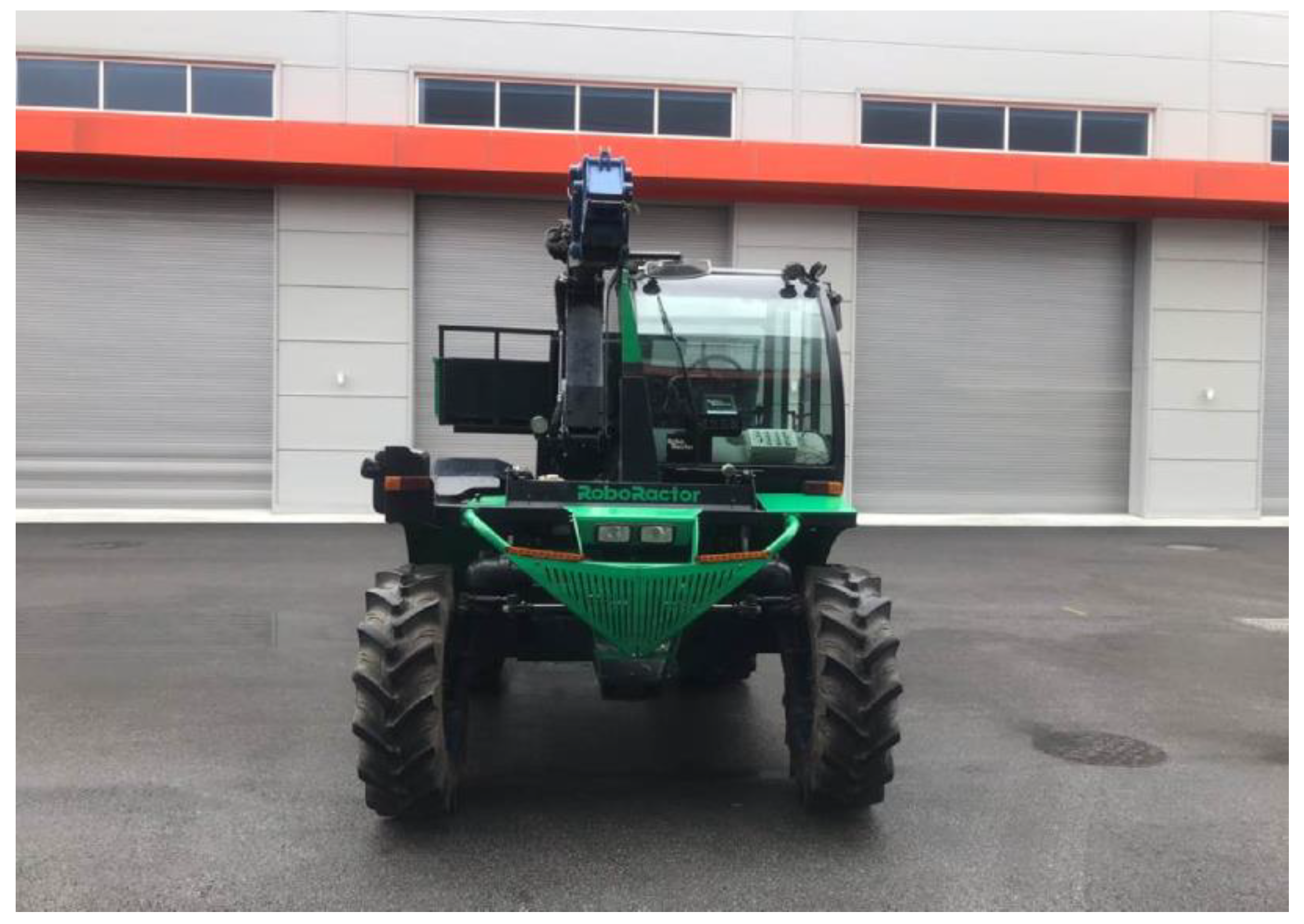
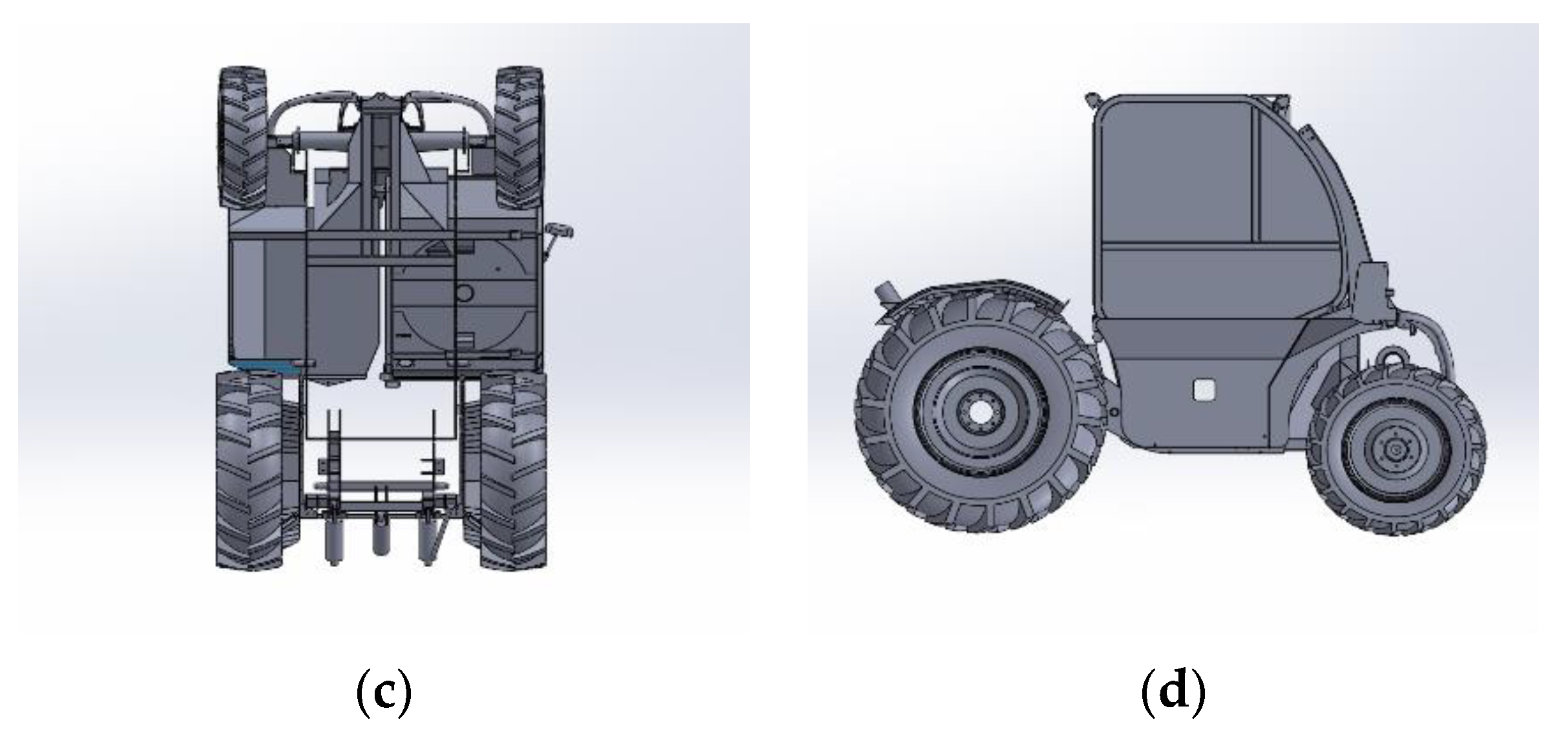
Figure 1 shows the developed multi-purpose agricultural machine. The machine has a rated engine power of 95.6 kW, six main gears, two sub-gears, and a maximum traveling speed of 48.81 km/h. The angle of static falling down sidelong and the minimum turning radius derived through the certified performance test were 45.3° and 3.06 m, respectively.
Table 1 shows the main specifications of the machine.
2.2. Theoretical Analysis from Literature Review
The lateral overturning and backward rollover characteristics of the multi-purpose agricultural machine were theoretically analyzed through literature review. For the simplicity of the analysis, it was assumed that the machine was composed of a main body and rear wheels that perform relative motions with each other. All components except for the front and rear wheels were assumed to be rigid bodies. Moreover, the ground was assumed to be very hard compared to wheels, and the ground reaction force generated by the front and rear wheels was assumed to act at a point on the ground plane. The air resistance that may occur during traveling was neglected. The position of the center of gravity was derived from the 3D model of the multi-purpose agricultural machine.
2.2.1. Lateral Overturning under Steady-State Turning Conditions
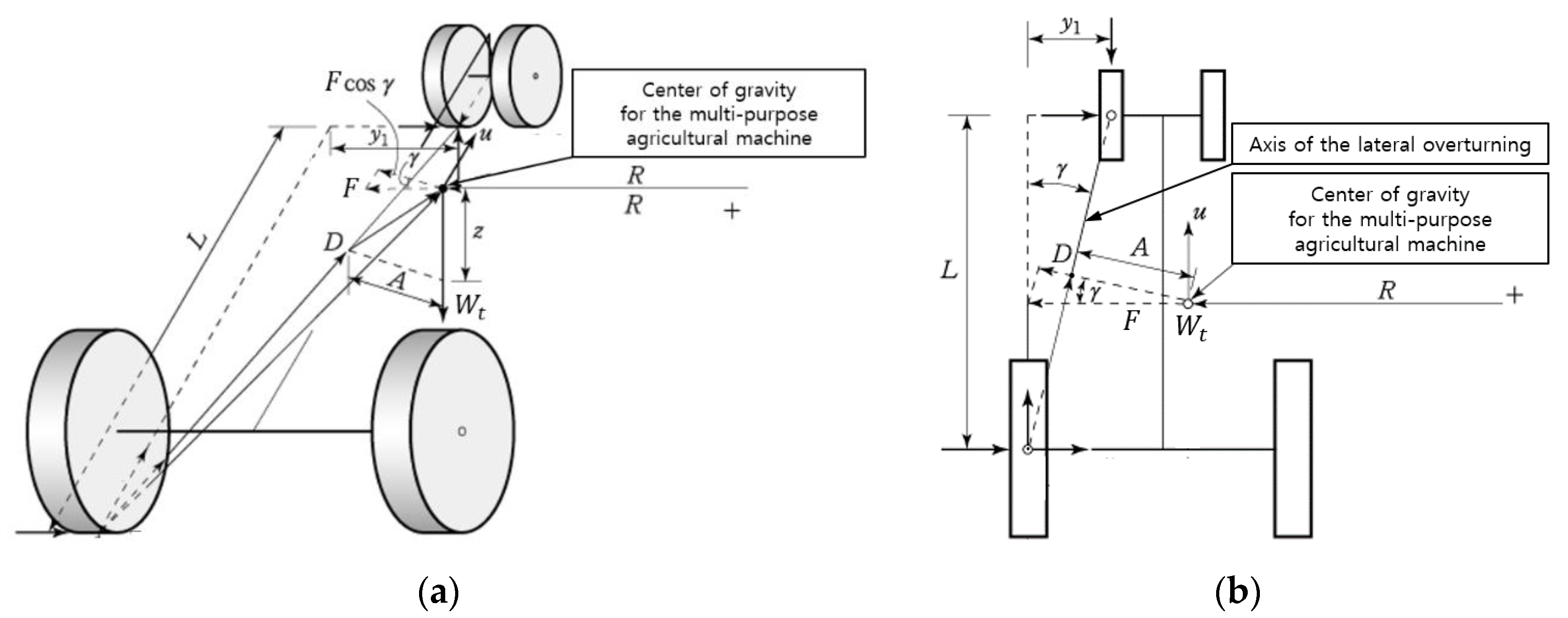
For the lateral overturning analysis, each component of the multi-purpose agricultural machine was expressed in a free body diagram, as shown in
Figure 2 [
13].
When a multi-purpose agricultural machine with total weight of
turns along a circle with a radius of R at a traveling speed of
under steady-state conditions, the lateral force acting on the wheels generates the moment of force at the center of gravity of the tractor. This moment acts in a direction that lifts the inner front and rear wheels. At the moment when these wheels are lifted, the lateral overturning of the multi-purpose agricultural machine occurs based on the axis of lateral overturning obtained by connecting the contact points of the outer front and rear wheels with the ground. The force acting on the center of gravity of the multi-purpose agricultural machine during turning under steady-state conditions can be determined through Equation (1) [
14]:
where:
Force acting on the center of gravity for the main body of the multi-purpose agricultural machine, N;
Total weight of the multi-purpose agricultural machine, N;
Traveling speed of the multi-purpose agricultural machine, m/s;
Gravitational acceleration, m/s2;
Turning radius, m.
is the angle between the direction of force acting on the center of gravity of the multi-purpose agricultural machine and the normal direction to the axis of lateral overturning which can be determined through Equation (2) [
13]:
where:
Angle between the directions of F and normal to the axis of lateral overturning, in degrees;
Horizontal distance between the front and rear wheels, in meters;
Wheelbase, in meters.
The traveling speed that causes lateral overturning by lifting the inner front and rear wheels is defined as the critical traveling speed. The critical traveling speed can be determined using Equation (3) [
13]:
where:
Critical traveling speed at which the lateral overturning occurs, in m/s;
Normal distance between the axis of lateral overturning and center of gravity, in meters;
Height of the center of gravity from the ground, in meters.
Table 2 shows the parameter values of the multi-purpose agricultural machine related to the lateral overturning equations.
2.2.2. Backward Rollover
For the backward rollover analysis, each component of the multi-purpose agricultural machine was expressed in a free body diagram, as shown in
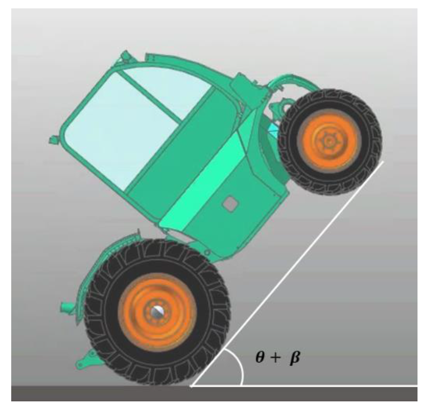
Figure 3. In the figure, the dotted lines represent the state in which the machine is lifted backwards as it rotates by
with respect to the
Y-axis based on the center of gravity of the main body [
13]. For the rotation direction, the counterclockwise direction was set as a positive direction. Therefore, when the moment is calculated based on the rear wheel center, the positive moment increases backward rollover, and the negative moment acts to inhibit backward rollover.
The moment generated at the rear wheel center by the self-weight of the main body of the multi-purpose agricultural machine is determined by the self-weight and moment arm
of the main body. As the self-weight acts vertically downward, this moment will always be negative. Therefore, the self-weight of the main body acts in the direction to inhibit backward rollover. In this instance,
is defined as the horizontal distance between the rear wheel center and the center of gravity of the main body, and it is determined through Equation (4) [
13]:
where:
Moment arm of self-weight of main body, in meters;
Distance between the rear wheel center and the center of the gravity of the main body, in meters;
Rotating angle of the main body with respect to the Y-axis, in degrees;
Inclination angle of slope, in degrees;
Angle between and X axis at the non-rotated position, in degrees.
If
,
, and
increase,
decreases, thereby reducing the backward rollover safety of the multi-purpose agricultural machine. If the sum of
,
, and
reaches 90°, backward rollover may occur because the rear wheel center and the center of gravity of the main body are aligned in a vertical direction. Under dynamic conditions, the main body may rotate until the sum of
,
, and
reaches 90° owing to the rotational force caused by the positive moment; thus, causing backward rollover. The angular velocity of the main body that allows the sum of
,
, and
to reach 90° for a certain rotating angle,
, is defined as the critical angular velocity. When the angular velocity of the main body reaches the critical angular velocity
, the kinetic energy by rotation causes backward rollover. Therefore, the backward rollover characteristics of the multi-purpose agricultural machine can be determined through
, as shown in Equation (5) [
13]:
where:
Critical angular velocity of the main body, in rad/s;
Weight of main body, in N;
Mass moment inertia of the main body with regarding to Y axis, in kg·m2.
Table 3 shows the parameter values of the multi-purpose agricultural machine related to backward rollover.
2.3. Dynamic Simulation
The lateral overturning and backward rollover characteristics of the multi-purpose agricultural machine were also analyzed using a multi-body dynamics software (Recurdyn V8R5, FunctionBay, Seongnam-si, Korea). This software has been widely used for vehicle dynamics and driving simulation analysis [
15].
2.3.1. 3D Modelling
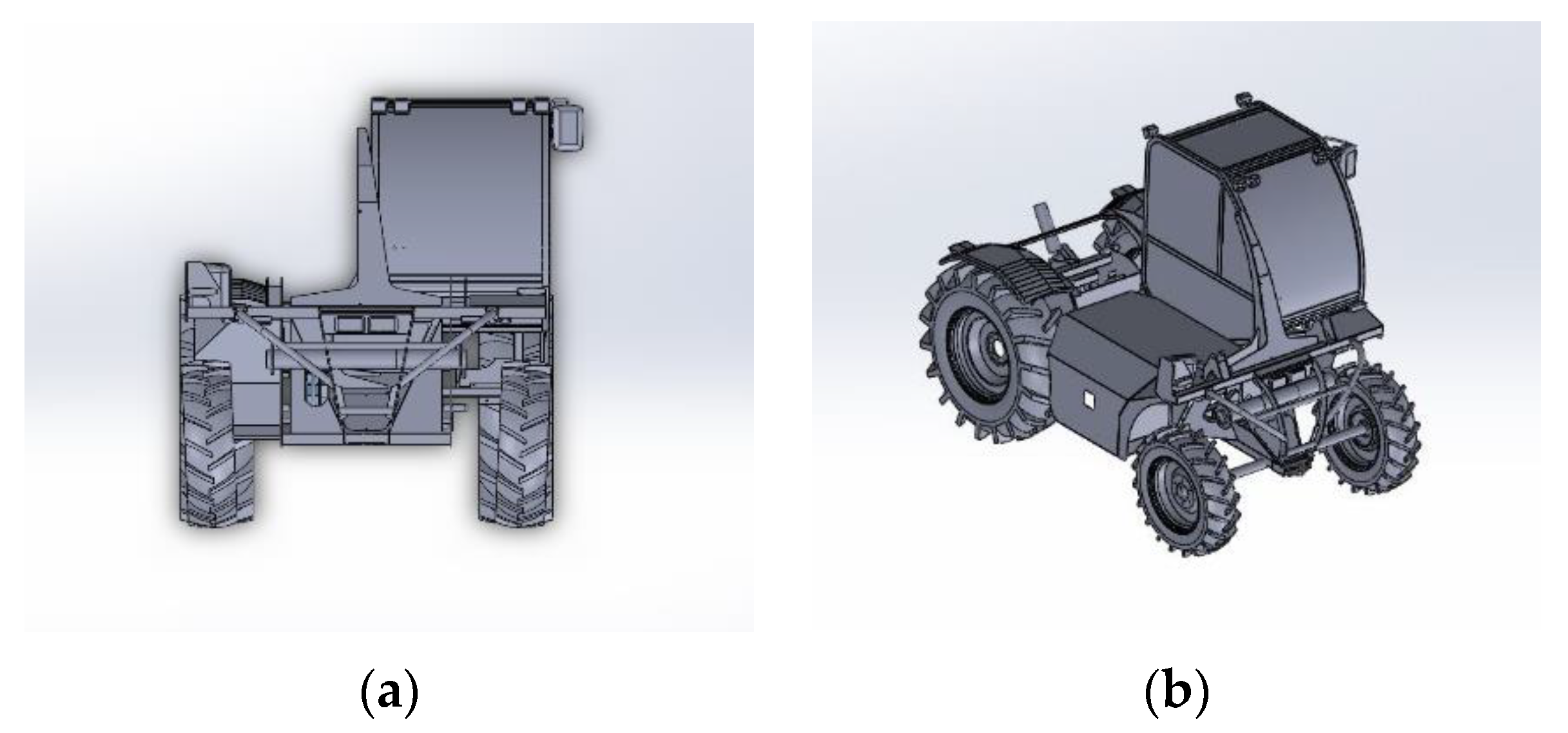
A 3D model composed of the main body, front wheels, and rear wheels was created by reflecting the production drawings and measured dimensions of the multi-purpose agricultural machine (
Figure 4).
2.3.2. Material Properties
To obtain accurate results in the dynamics simulation, the material properties and simulation parameters of each component of the multi-purpose agricultural machine must be entered accurately. The material properties in the simulation were entered considering the actual properties of the multi-purpose agricultural machine. The main body, power transmission system, and axles are made of alloy steel (STL1250), whereas the exterior frame and wheel rims are made of stainless steel (STS304). In addition, the wheel tires are made of synthetic rubber. The material properties of each component of the machine required for simulation, such as Poisson’s ratio, shear modulus, and density, were obtained through literature review for the actual materials. The ground was assumed to be very hard compared to the wheels. The coefficients of dynamic friction and static friction between the wheels and the ground as well as the stiffness of the wheels were also derived through literature review.
Table 4 shows the derived material properties and simulation parameters [
16,
17,
18,
19,
20]. The gravitational acceleration was set to act vertically downward at a magnitude of 9.81 m/s
2.
2.3.3. Verification of Simulation Model
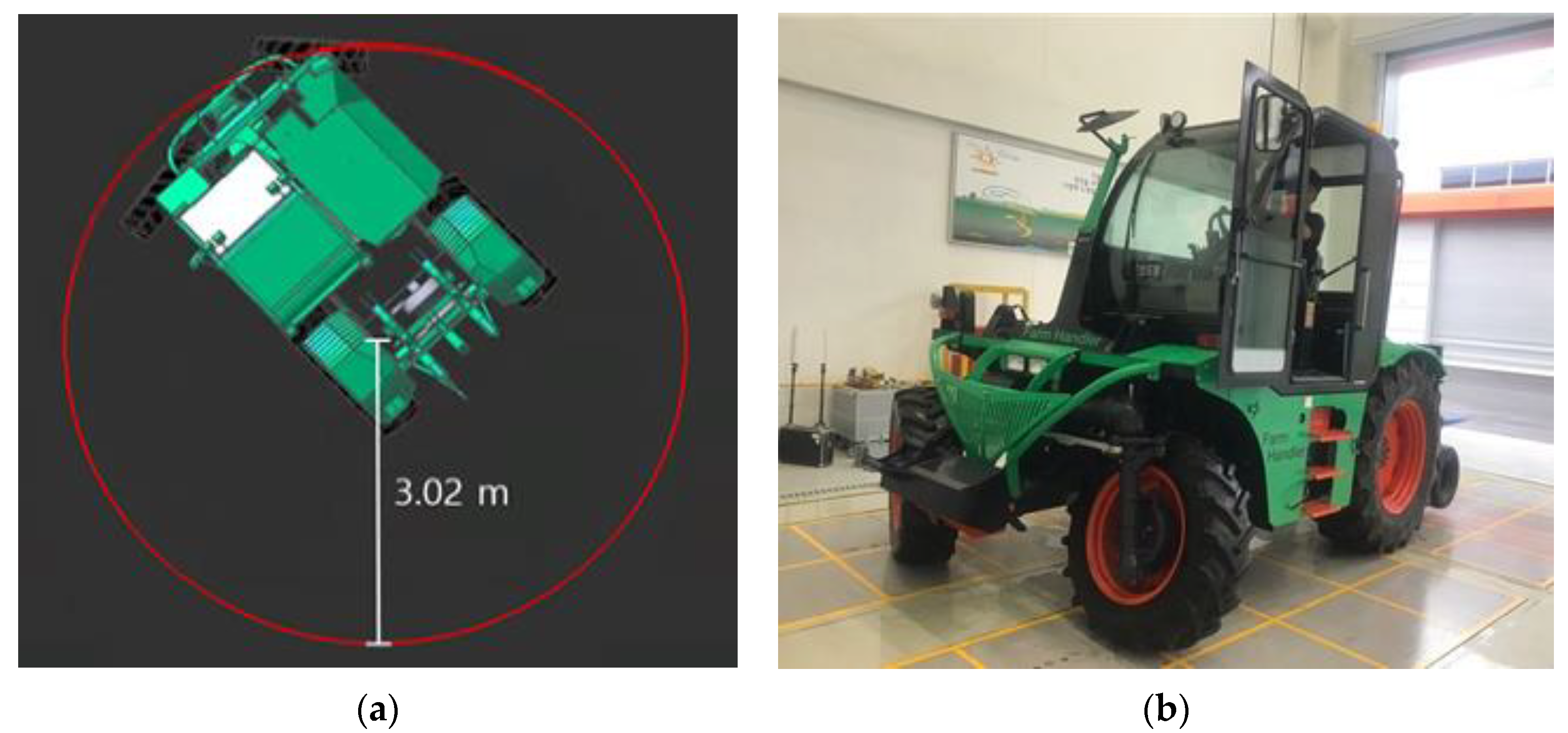
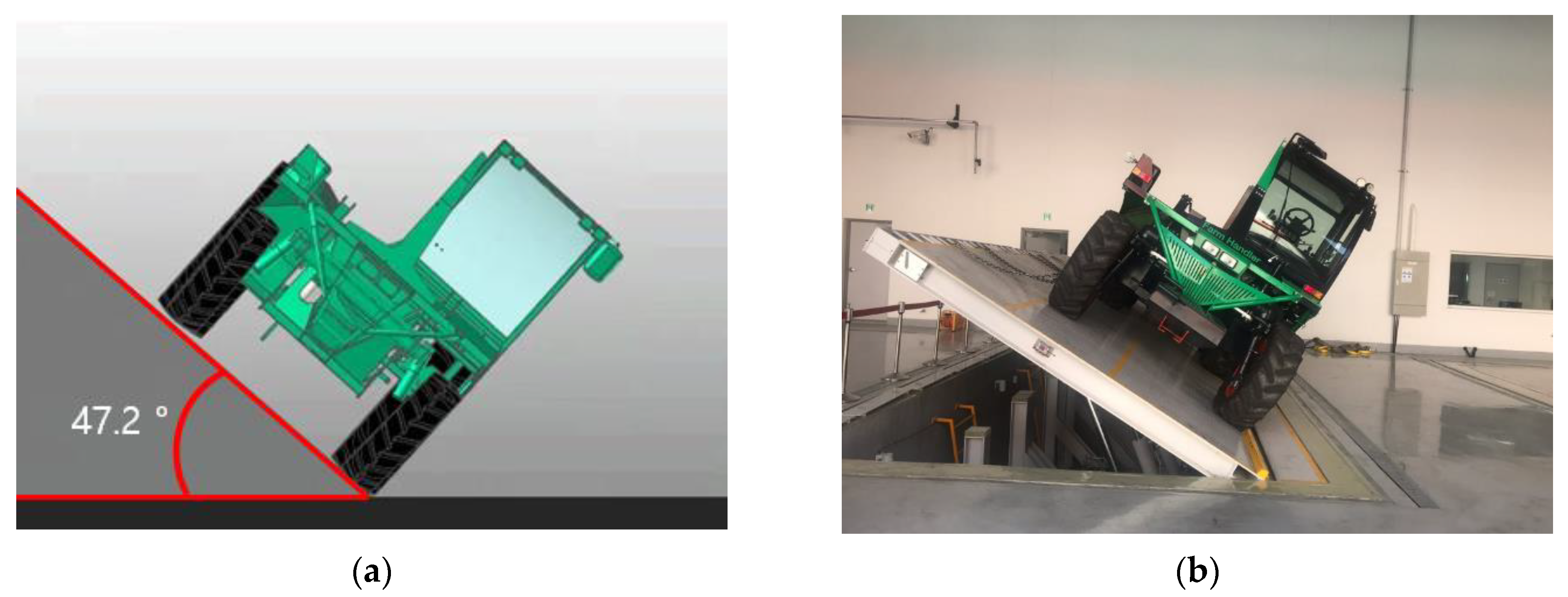
The minimum turning radius and angle of static falling down sidelong of the multi-purpose agricultural machine were derived using the created simulation model (
Figure 5 and
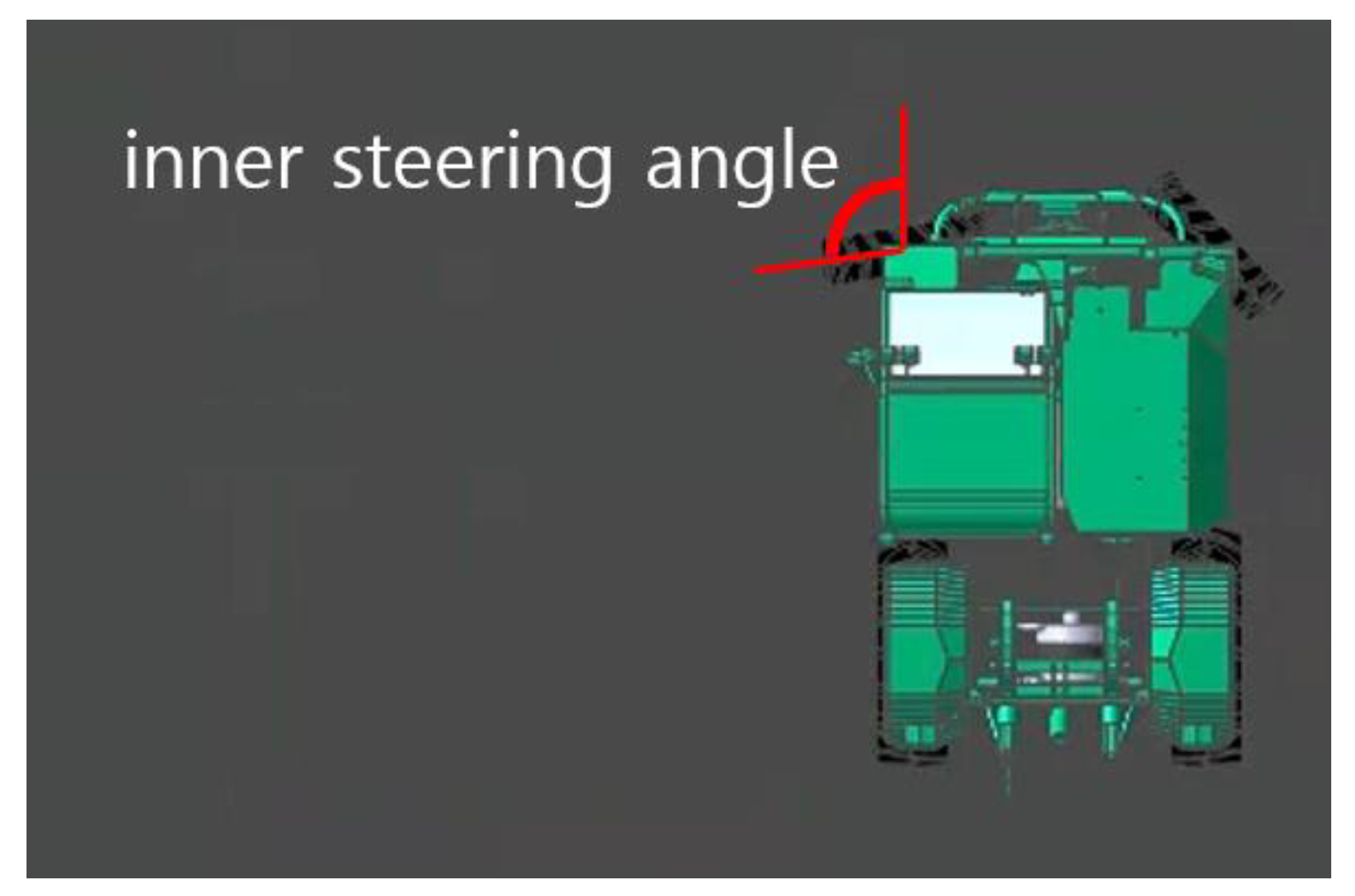
Figure 6). The minimum turning radius refers to the radius of the circle drawn by the center of the outer front wheel when the machine makes a turn at the lowest speed while the inner steering angle is set to its maximum. In addition, the angle of static falling down sidelong refers to the inclination angle of the ground at which the machine placed on it begins to roll off sideways. The simulation results showed that the minimum turning radius was 3.02 m when the inner steering angle of the machine was set to its maximum value of 100° and the machine traveled at the lowest speed of 1.86 km/h. In addition, the angle of static falling down sidelong was found to be 47.2°.
The minimum turning radius and angle of static falling down sidelong of the multi-purpose agricultural machine derived through simulation were compared with the measured values in the certified performance test (
Table 5). The errors of the simulation results compared to the measured values were found to be 1.31% for the minimum turning radius and 4.19% for the angle of static falling down sidelong. Because the errors were less than 5%, the created simulation model can be regarded to be valid [
21].
2.4. Analysis Conditions
The conditions for analyzing the lateral overturning and backward rollover characteristics of the multi-purpose agricultural machine are as follows.
2.4.1. Lateral Overturning under Steady-State Turning Conditions
When the multi-purpose agricultural machine traveled under steady-state conditions, the critical traveling speed at which the lateral overturning occurred was obtained according to the inner steering angle. The critical traveling speed was derived theoretically and by dynamic simulation while the inner steering angle was increased from 5° to a maximum value of 100° by intervals of 5° (
Figure 7).
2.4.2. Backward Rollover
When the front wheels of the multi-purpose agricultural machine were lifted at a certain angle, the critical angular velocity according to the front wheel lift angle was theoretically derived by dynamic simulation (
Figure 8). The front wheel lift angle represents the sum of
and
in
Figure 3. The front wheel lift angle was set to eight levels (1°, 5°, 10°, 20°, 30°, 40°, 50°, and 60°), considering the actual work environment.
In addition, the theoretical traveling speed at which the backward rollover occurs was derived according to the front wheel lift angle. The rotation speed of the rear wheels at which backward rollover occurs was derived through simulation, and it was converted into the theoretical traveling speed by multiplying it by the rolling radius of the wheel. In the simulation, the rotation speed of rear wheels was set to reach the target value in 0.01 s.
3. Results and Discussion
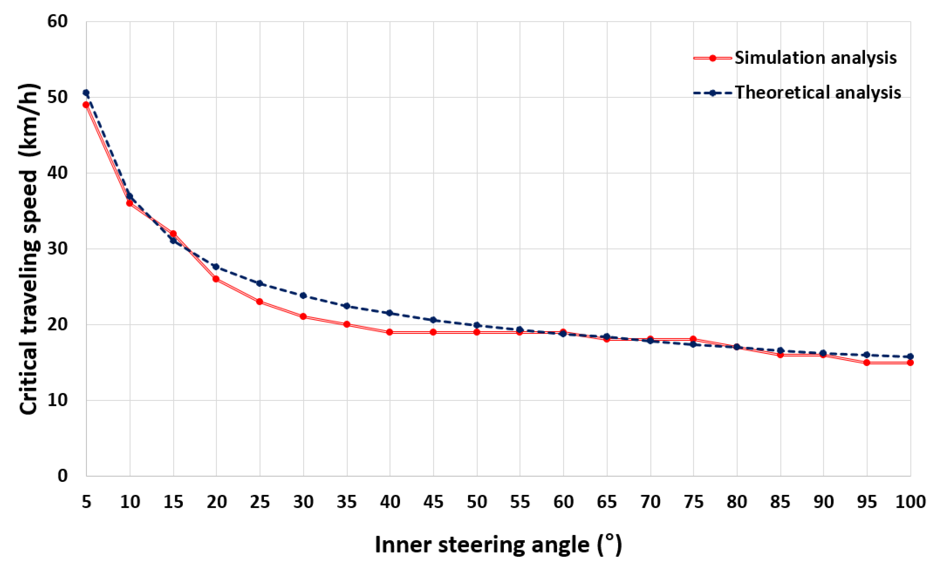
3.1. Lateral Overturning Characteristics under Steady-State Turning Conditions
Figure 9 shows the theoretical analysis and dynamic simulation results for the lateral overturning of the multi-purpose agricultural machine. The ANOVA results showed that there was no significant difference between the theoretical and simulation results at the 5% significance level (
Table 6). The simulation conditions were set to be same with the actual operating conditions, and maybe this consistency made both results very similar.
In the theoretical analysis, lateral overturning occurred at a traveling speed of 50.55 km/h when the inner steering angle of the multi-purpose agricultural machine was 5°, which was the minimum value. When the inner steering angle was 100°, which was the maximum value, lateral overturning occurred at a traveling speed of 15.7 km/h. In the simulation, lateral overturning occurred at a traveling speed of 49 km/h when the inner steering angle of the machine was 5°. When the inner steering angle was 100°, lateral overturning occurred at a traveling speed of 15 km/h. In both the analyses, the critical traveling speed showed a tendency to decrease as the inner steering angle increased. Simply, the risk of lateral overturning increases as the steering angle increases.
Because the maximum traveling speed of the multi-purpose agricultural machine is 48.8 km/h, lateral overturning does not occur for all speeds when the steering angle is 5°. In addition, when the traveling speed is less than 15 km/h, lateral overturning does not occur for all steering angles. Agricultural tasks using working implements, such as a plow, rotavator, seeding machine, transplanter, sprayer, and harvester, are usually performed at a traveling speed of less than 12.3 km/h [
22,
23,
24,
25,
26,
27]. When the multi-purpose agricultural machine operated with such working implements, the critical traveling speed is expected to decrease because the position of the center of gravity becomes higher. However, as the traveling speed is also reduced accordingly, the machine is expected to be safe against lateral overturning. Further research is required on the critical traveling speed when the multi-purpose agricultural machine travels with various working implements on a slope.
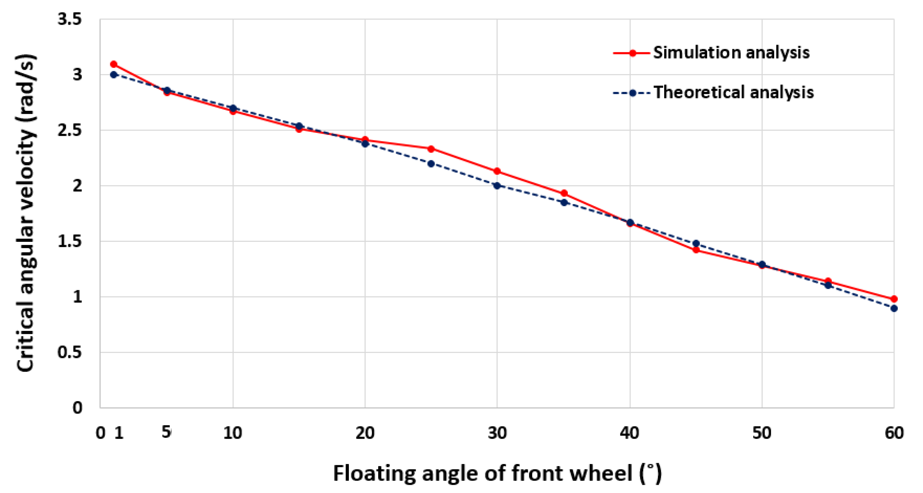
3.2. Backward Rollover Characteristics
Figure 10 shows the theoretical analysis and dynamic simulation results for the backward rollover of the multi-purpose agricultural machine. It was found that there was no significant difference between the theoretical and simulation results at the 5% significance level (
Table 7).
In the theoretical analysis, the critical angular velocities at which backward rollover occurs were found to be 3 and 0.9 rad/s when the front wheel lift angles were 1° and 60°, respectively. In the simulation, the critical angular velocities were found to be 3.09 rad/s and 0.98 rad/s when the front wheel lift angles were 1° and 60°, respectively. In both the analyses, the critical angular velocity showed a tendency to decrease as the front wheel lift angle increased. Simply, the risk of backward rollover increases as the front wheel lift angle increases.
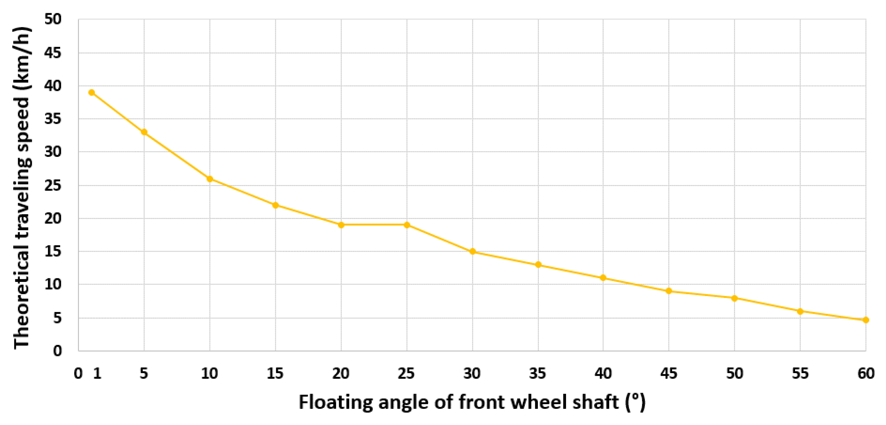
Figure 11 shows the theoretical traveling speed at which the backward rollover occurs according to the front wheel lift angle. When the front wheel lift angles were 1°, 30°, and 60°, the theoretical traveling speeds at which backward rollover occurs were found to be 39, 15, and 5 km/h. Considering the work environment of the multi-purpose agricultural machine, the front wheels can be lifted by ridges, uneven ground, and obstacles. Therefore, it appears that an environment in which the front wheel lift angle does not exceed 30° is required to prevent backward rollover under the condition of 12.3 km/h, which is the typical traveling speed of the multi-purpose agricultural machine for agricultural tasks.
When the machine travels with working implements, the critical angular velocity and theoretical traveling speed at which backward rollover occurs are expected to vary owing to the increase in the mass moment of inertia and weight. Further research is required on the backward rollover characteristics when the multi-purpose agricultural machine travels with various working implements on a slope.
4. Conclusions
In this study, theoretical analysis and dynamic simulation were conducted to analyze the characteristics of lateral overturning under steady-state turning conditions and backward rollover for a multi-purpose agricultural machine recently developed in South Korea.
For theoretical analysis, free body diagrams were prepared considering the actual dimension of each component of the multi-purpose agricultural machine. In addition, theoretical equations to analyze lateral overturning and backward rollover were derived through literature review. For dynamic simulation analysis, a simulation model was created based on the actual dimensions and material properties of the multi-purpose agricultural machine. The simulation model was verified by comparing the certified performance test.
The lateral overturning characteristics of the multi-purpose agricultural machine was analyzed using theoretical equations and a simulation model. The critical traveling speed at which lateral overturning occurs was derived while varying the inner steering angle to a maximum value of 100°. In both the theoretical and simulation analysis results for lateral overturning, the critical traveling speed decreased, and thus, lateral overturning safety decreased as the steering angle increased. In addition, it was confirmed that the lateral overturning does not occur for all steering angles when the multi-purpose agricultural machine travels at a speed of less than 15 km/h. Considering that typical agricultural tasks, which are usually performed at a traveling speed of less than 12.3 km/h, it appears that lateral overturning safety will be secured if such tasks are performed using a multi-purpose agricultural machine.
In the backward rollover analysis, the critical angular velocity of the main body at which backward rollover occurs was derived while varying the front wheel lift angle of the multi-purpose agricultural machine to a maximum of 60°. In addition, the theoretical traveling speed at which backward rollover occurs was derived. In both theoretical and dynamic simulation results, the critical angular velocity of the main body showed a tendency to decrease; thus, backward rollover safety decreased as the front wheel lift angle increased. The theoretical traveling speeds was found to be 15 km/h when the front wheel lift angle of the multi-purpose agricultural machine was 30°. Therefore, it appears that an environment in which the front wheel lift angle does not exceed 30° is required to prevent backward rollover when the multi-purpose agricultural machine is used for typical agricultural tasks.
In the future, various working implements will be attached to the multi-purpose agricultural machine and driving simulation will be performed on a slope with obstacles for the analysis of lateral overturning and backward rollover characteristics in more realistic agricultural environments.
Author Contributions
Theoretical and simulation analysis, S.-J.H., M.-K.J.; writing—original draft preparation, S.-J.H.; writing—review and editing, J.-S.N. All authors have read and agreed to the published version of the manuscript.
Funding
This work was supported by the Korea Institute of Planning and Evaluation for Technology in Food, Agriculture and Forestry (IPET) through the Agriculture, Food and Rural Affairs Convergence Technologies Program for Educating Creative Global Leaders Program, funded by the Ministry of Agriculture, Food and Rural Affairs (MAFRA) (716001-7). This work was also supported by the Korea Institute of Planning and Evaluation for Technology in Food, Agriculture, Forestry (IPET) through the Advanced Production Technology Development Program, funded by the Ministry of Agriculture, Food and Rural Affairs (MAFRA) (319041-03).
Institutional Review Board Statement
Not applicable.
Informed Consent Statement
Not applicable.
Conflicts of Interest
The authors declare no conflict of interest.
References
- Park, H.K.; Kim, K.U.; Kim, J.W.; Song, T.Y.; Park, M.S.; Cho, K.H. Sideways Overturning Analysis of Forwarder Using a Multibody Dynamics Analysis Program. J. Biosyst. Eng. 2002, 27, 185–194. [Google Scholar]
- Ministry of Agriculture, Forestry and Fisheries: Outline of Fatal Accidents During Farm Work in 2015. Available online: http://www.maff.go.jp/j/seisan/sien/sizai/s_kikaika/anzen/pdf/sibou24.pdf (accessed on 21 May 2020).
- Rural Development Administration: 2012 Agricultural Machinery Safety Accident. Available online: http://www.nongsaro.go.kr/portal/ps/psb/psbk/kidofcomdtyDtl.ps?menuId=PS00067&kidofcomdtyNo=28785 (accessed on 7 November 2020).
- Abubakar, M.S.; Ahmad, D.; Akande, F.B. A Review of Farm Tractor Overturning Accidents and Safety. Pertanika J. Sci. Technol. 2010, 18, 377–385. [Google Scholar]
- Hyun, D.Y. Computer Simulation of Sideways Overturning of Agricultural Tractor. Master’s Thesis, Seoul National University, Suwon, Korea, 1987. [Google Scholar]
- Kim, K.U.; Rehkugler, G.E. A Review of Tractor Dynamics and Stability. Trans. ASAE 1987, 30, 615–623. [Google Scholar]
- Ahmadi, I. Dynamics of Tractor Lateral Overturn on Slopes under the Influence of Position Disturbances (model development). J. Terramechanics. 2011, 48, 339–346. [Google Scholar] [CrossRef]
- Baker, V.; Guzzomi, A.L. Model and Comparison of 4-wheel-drive Fixed-chassis Tractor Rollover during Phase I. Biosyst. Eng. 2013, 116, 179–189. [Google Scholar] [CrossRef]
- Li, X.; Wang, G.; Yao, Z.; Qu, J. Dynamic Model and Validation of an Articulated Steering Wheel Loader on Slopes and Over Obstacles. Veh. Syst. Dyn. 2013, 51, 1305–1323. [Google Scholar] [CrossRef]
- Mitchell, B.W.; Zachariah, G.L.; Liljedahl, J.B. Prediction and Control of Tractor Stability to Prevent Rearward Overturning. Trans. ASAE 1972, 15, 838–844. [Google Scholar] [CrossRef]
- Smith, D. Safe Tractor Operation: Rollover Prevention. Available online: http://agsafety.tamu.edu/farm-andranch-safety (accessed on 3 December 2020).
- Shim, S.B.; Nam, Y.J.; Koo, Y.M. Conceptual Design and Rearward Stability Analysis of an Integrated Tractor Implement for Flat Ridge Preparation. J. Agric. Life Sci. 2018, 52, 111–122. [Google Scholar] [CrossRef]
- Ryu, K.H.; Kim, K.U.; Kim, S.T.; Park, K.J.; Park, S.J.; Park, J.G.; Seo, S.Y.; Shin, B.S.; Yeon, K.S.; Lee, G.S.; et al. Tractor Engineering Principle, 1st ed.; Moon Woon Dang: Seoul, Korea, 2004; pp. 384–420. [Google Scholar]
- Goering, C.E.; Stone, M.L.; Smith, D.W.; Turnquist, P.K. Off-Road Vehicle Engineering Principles, 1st ed.; ASAE: St Joseph, MI, USA, 2003; pp. 421–462. [Google Scholar]
- Noh, J.S.; Cho, Y.J.; Kim, T.S.; Lee, D.H.; Lee, K.S. Driving Running Stability of Orchard Aerial Lift by Using Recurdyn that is Dynamic Analysis Tool. Proc. Conf. Korean Soc. Agric. Mach. 2012, 17, 153–159. [Google Scholar]
- Jang, S.W.; Lim, M.S. Robust Design Technology for Plastic Parts Reliability, 1st ed.; Kijeon Research Center: Seoul, Korea, 2006; pp. 344–352. [Google Scholar]
- Wang, J.; Zou, D.; Wang, J.; Zhou, W. Testing and Analysis of the Shear Modulus of Urea Granules. IFIP Adv. Inf. Commun. Technol. 2014, 419, 137–144. [Google Scholar] [CrossRef]
- Hofstee, J.W.; Huisman, W. Handling and Spreading of Fertilizers Part 1: Physical Properties of Fertilizer in Relation to Particle Motion. J. Agric. Engng. Res. 1990, 47, 213–234. [Google Scholar] [CrossRef]
- Olieslagers, R.; Ramon, H.; De Baerdemaeker, J. Calculation of Fertilizer Distribution Patterns from a Spinning Disc Spreader by Means of a Simulation Model. J. Agric. Engng. Res. 1996, 63, 137–152. [Google Scholar] [CrossRef]
- Juvinall, R.C.; Marshek, K.M. Machine Component Design, 5th ed.; WILEY (John Wiley & Sons): Hoboken, NJ, USA, 2015; pp. 841–847. [Google Scholar]
- Ahn, Y.S.; Baek, W.K. Thrust Simulation and Experiments for Underwater Thrusters. J. Korean Soc. Power Syst. Eng. 2017, 21, 51–59. [Google Scholar]
- Singh, A.; Nawayseh, N.; Singh, L.P.; Singh, S.; Singh, H. Whole Body Vibration Exposure during Rotary Soil Tillage Operation: The Relative Importance of Tractor Velocity, Draft and Soil Tillage Depth. Int. J. Automot. Mech. Eng. 2018, 15, 5927–5940. [Google Scholar] [CrossRef]
- Ghate, S.R.; Perry, C.D. Ground Speed Control of Pesticide Application Rates in a Compressed Air Direct Injection Sprayer. Trans. ASAE 1994, 37, 33–38. [Google Scholar] [CrossRef]
- Jang, J.H.; Kim, W.S.; Choi, C.H.; Park, S.U.; Kim, Y.J. Analysis of Power Requirement of the Underground Crop Harvester Attached on Agricultural Tractor During Traction Operation. J. Korea Inst. Inf. Electron. Commun. Technol. 2018, 11, 150–155. [Google Scholar]
- Godwin, R.J.; O’Dogherty, M.J.; Saunders, C.; Balafoutis, A.T. A Force Prediction Model for Mouldboard Ploughs Incorporating the Effects of Soil Characteristic Properties, Plough Geometric Factors and Ploughing Speed. Biosyst. Eng. 2007, 97, 117–129. [Google Scholar] [CrossRef]
- Tsuga, K. Development of Fully Automatic Vegetable Transplanter. Jpn. Agric. Res. Q. 2000, 34, 21–28. [Google Scholar]
- Da Silveira, J.C.M.; Fernandes, H.C.; Modolo, A.J.; de Lima Silva, S.; Trogello, E. Furrow Depth, Soil Disturbance Area and Draft Force of a Seeder-fertilizer at Different Seeding Speeds. Rev. Ceres. 2011, 58, 293–298. [Google Scholar]
| Publisher’s Note: MDPI stays neutral with regard to jurisdictional claims in published maps and institutional affiliations. |
© 2021 by the authors. Licensee MDPI, Basel, Switzerland. This article is an open access article distributed under the terms and conditions of the Creative Commons Attribution (CC BY) license (http://creativecommons.org/licenses/by/4.0/).


