Article

Topological Defect-Guided Regular Stacking of Focal Conic Domains in Hybrid-Aligned Smectic Liquid Crystal Shells

Department of Physics & Materials Science, University of Luxembourg, 162a, Avenue de la Faiencerie, 1511 Luxembourg, Luxembourg
*
Author to whom correspondence should be addressed.
Crystals 2021, 11(8), 913; https://doi.org/10.3390/cryst11080913
Submission received: 11 July 2021 / Revised: 31 July 2021 / Accepted: 1 August 2021 / Published: 4 August 2021
(This article belongs to the Special Issue In Celebration of Noel A. Clark’s 80th Birthday)

Abstract

:
We study liquid crystal (LC) shells in hybrid configuration (director tangential to the inside but normal to the outside) as they slowly undergo a transition from a nematic (N) to a smectic-A (SmA) phase. Every shell has two antipodal +1 topological defects, at the thinnest and thickest points, respectively. On cooling from N to SmA, the symmetry axis connecting the defects gradually reorients from along gravity to perpendicular to it, reversibly and continuously, if the LC and aqueous phase are density matched at the N-SmA transition. This suggests reduced density near the defects—reflecting a local reduction in order—under the strong confinement with antagonistic boundary conditions. In the SmA phase, a regular array of focal conic domains (FCDs) develops, templated in position and orientation by the +1 defect at the thinnest point. Around this defect, a single complete toroidal FCD always develops, surrounded by incomplete FCDs. In contrast to similar FCD arrangements on flat aqueous interfaces, this is a stable situation, since the two +1 defects are required by the spherical topology. Our results demonstrate how the topological defects of LC shells can be used to template complex self-organized structures. With a suitable adaption of the LC chemistry, shells might serve as a basis for producing solid particles with complex yet highly regular morphologies.

1. Introduction

The liquid crystal (LC) nematic (N) to smectic-A (SmA) transition under confinement between boundaries imposing orthogonal anchoring of the director n (the axis of uniaxial cylindrical symmetry, also giving the average orientation of the molecular long axes [1]) constitutes a very rich system for soft matter self-organization studies, since this configuration induces a frustrated situation in the SmA phase that does not exist in the N phase. The latter easily adapts to the boundary conditions by adopting a continuous bend in the director field, n ( r ) , from one boundary to the other, but the SmA phase cannot accommodate bend due to its one-dimensional positional order with molecules arranging in layers that orient perpendicularly to n [1,2]. This inability is often reflected in the N phase upon approaching the N-SmA transition, as a divergence of the elastic constant K 3 , describing the energy density of bend deformation. A pure bend from the tangential to the normal boundary thus becomes exceedingly expensive in free energy and it was early on recognized that the nematic can reduce its free energy by modulating the bend with a periodic twist deformation [3], with the saddle-splay constant K 24 playing a key role [4,5,6,7,8,9]. The effect is easily recognized in polarizing microscopy of a hybrid-aligned LC undergoing the N-SmA transition, as a periodic pattern of stripes parallel to the average n at the tangential interface [10]. These stripes and their complete elucidation attract much interest until this day, with several teams having built an increasingly refined understanding [11,12,13,14].
Once the LC is cooled below the transition into the SmA phase, the modulated bent director field configuration becomes unstable and the stripe pattern breaks up into a beautiful pattern that often resembles a flower [15,16], the surface being tiled with circular domains that may be partially overlapping. These are focal conic domains (FCDs) [1,2,17,18,19,20] in which the conflicting boundary conditions are handled by the smectic layers bending, rather than the director, which instead exhibits a splay deformation, as allowed in SmA. Once the fascinating physics of why the FCDs form was understood, experimentalist researchers developed means of directing their development with control of size and into regular arrays [21,22,23,24] and several teams have demonstrated that the FCDs have application potential in the form of microlenses [25,26].
Recently, Gim et al. also demonstrated that topological defects present in a hybrid-aligned nematic film confined between a water phase and air (providing tangential and normal alignment, respectively), which is then cooled into the SmA phase in order to form FCDs, significantly influence the trajectory along which the FCDs develop [14]. The water substrate is interesting as it provides a tangential alignment that is perfectly degenerate, i.e., no particular orientation of n ( r ) within the water–LC interface is favored. As a result, integer topological defects spontaneously develop (the bend in n ( r ) causes a polar symmetry and thus precludes the formation of half-integer defects [7]) across the nematic LC as it forms upon cooling from the isotropic phase. As the interface is flat, the total topological charge is zero; hence, there is always an equal number of +1 and −1 defects in the sample. The defects exist only at the tangential-aligned interface (they are surface defects, or boojums) since the normal n ( r ) at the air interface is always defect-free. For the +1 defects, the bend from the water to the air interface can be oriented in two directions, ‘away from’ or ‘towards’ the defect. The authors note that these ‘diverging’ and ‘converging’ versions of the +1 defect in the hybrid-aligned nematic give rise to distinctly different trajectories as the FCDs in the SmA phase form. The converging +1 defect has the ideal director field for an FCD, and therefore this +1 defect seeds a complete toroidal FCD, around which adjacent incomplete and elliptic–hyperbolic FCDs develop outwards, partially covered by their respective neighbor. In contrast, n ( r ) around the diverging +1 defect is incompatible with the FCD formation, forcing it to undergo a significant rearrangement as FCDs are formed; hence, this defect does not act as an FCD seed. The pattern with incomplete elliptic–hyperbolic FCDs is a transient state at the flat aqueous interface, and the SmA phase eventually relaxes to a configuration with regularly spaced complete toroidal FCDs, covering the entire sample area.
In this context, a system for studying the N-SmA transition in hybrid configuration that is particularly interesting is that of thin spherical shells, typically produced using microfluidic methods as a double emulsion of water inside LC inside water [27,28]. If n ( r ) at an LC–water interface is tangential, the spherical topology requires that topological defects with a total charge of +2 develop at that interface [28,29]; hence, not only can we expect to see the impact of defects on the FCD formation in a hybrid-aligned shell, but we also see the impact of positive-signed defects only, without the influence of the negative-signed defects that must be present at equal magnitude at any flat interface. Moreover, each hybrid-aligned shell exhibits one converging and one diverging +1 defect, positioned antipodally at the thinnest and thickest points of the shell [29,30,31]. The required hybrid alignment is easy to achieve in LC shells since the stabilizers added to the aqueous phase also dictate what alignment is achieved: polyvinylalcohol (PVA) supports tangential alignment while surfactants typically promote normal alignment; hence, PVA in the inner phase and surfactant in the outer phase, or vice versa, produce the desired hybrid configuration [29,30]. Interestingly, shells with hybrid configurations can even be produced when surfactants are used in both phases [32] and with block copolymer stabilizers [31] or with mixtures of stabilizers [32]; the configuration may be tuned dynamically by varying the temperature. Hence, LC shells offer a highly versatile platform for studying LC reorganization phenomena.
We previously confirmed both the development of stripes along the average tangential-side n as hybrid-aligned nematic shells were cooled towards the transition to a SmA phase, and the development of FCDs once the phase transition has taken place [33,34], but in these studies the cooling was too fast for a full equilibrium SmA texture to develop. Moreover, we did not investigate in detail how the FCDs develop around the converging and the diverging +1 defect, respectively, nor did we study the impact of density mismatch between the LC and the inner phase, which renders the shells asymmetric. In this paper, we study LC shells as they undergo an N-SmA transition very slowly (0.01 K/min) and we compare the cases where the inner droplet is always lighter than the LC, making the shell thin at the top and thick at the bottom, with two cases of density matching in the LC temperature range; because the temperature dependence of the LC density is much greater than that of the water density, it is only possible to density match for one temperature. We find an interesting reorientation behavior in the gravitational field of shells that are density matched at the N-SmA transition, which suggests that the defects constitute reduced-density points within the shell, and we see that the converging +1 defect, always situated at the thinnest shell side, indeed templates a complete toroidal FCD. The surrounding incomplete FCDs never anneal into complete toroidal FCDs as at a flat LC–water interface, most likely due to the permanence of the two +1 topological defects at the top and bottom of the shell.

2. Materials and Methods

Shells were produced using the now standard microfluidic technique with nested glass capillaries first introduced by Weitz and co-workers [35]. Our experimental parameters were identical to those described in [36]. The innermost disperse phase and the outermost continuous phase were both aqueous solutions of interface stabilizers. To ensure tangential alignment at the inner interface, we added 1% by mass of polyvinylpyrrolidone (PVP, M w = 1.3 Mg mol 1 , Sigma-Aldrich) to the inner aqueous phase, while the outer aqueous phase contained 1% by mass of the surfactant sodium dodecyl sulfate (SDS, Sigma-Aldrich), ensuring normal alignment on the shell outside. The asymmetric boundary conditions give rise to a hybrid n ( r ) with two +1 defects on the tangential-aligned interface, situated at the thinnest and thickest points of the shell, respectively. As illustrated in Figure 1a, one defect must be of the convergent type (hyperbolic director field in the cross section through the shell symmetry axis) while the other must be of the divergent type (radial director field in the same cross section), but it is not per se obvious whether the former is at the thinnest point (top case in Figure 1a) or at the thickest point (bottom case). We will see in the results section that only the former develops, in contrast to what has been suggested previously [29,30].
As LC, we use a mixture, similar to [36], of the commonly used SmA-forming mesogen 8CB (4-cyano-4 -octylbiphenyl) and the reactive nematogen RM257 (1,4-bis-[4-(3-acryloyloxy-propyloxy)benzoyloxy]-2-methylbenzene), both from Synthon (Germany). We do not polymerize the RM257 in this study; its main role here is to reduce the phase transition temperatures compared to those of pure 8CB and to bring the density of the LC near the N-SmA transition close to that of water at the same temperature. With 10% by mass of RM257, the N-SmA transition takes places at T N S = 23.6 ° C (rather than 40.5 ° C for pure 8CB). The first-order clearing transition (N-isotropic transition) is distributed over a temperature range, as this is a mixture, taking place around T N I ≈ 35–36 ° C.
The density of regular water can safely be approximated as constant at 1.0 g cm 3 in the temperature range from 20 to 35 ° C. The density of 8CB has been reported to change from ∼0.98 g cm 3 just below the isotropic–nematic transition to ∼1.0 g cm 3 around room temperature [37]. Although we have not determined the densities of our mixture as a function of temperature, we have empirically confirmed that the behavior is qualitatively similar to that of 8CB, with the significant difference that, throughout the nematic and smectic phases, ρ L C is greater than ρ a q 1 of the inner aqueous phase based on regular water. An inner droplet of PVP in H 2 O thus rises within the LC, rendering the corresponding shell the thinnest at the top and thickest at the bottom. As the temperature dependence of ρ L C is much greater than that of the aqueous phase density, we can density match the aqueous phase to the LC at a certain temperature by mixing in heavy water (D 2 O) to the inner aqueous droplet. In this way, we produce two additional inner aqueous phases with ρ a q 2 = ρ L C in the nematic phase, and ρ a q 3 = ρ L C at T N S . The expected position of the inner droplet within the LC shell is schematically illustrated as a function of temperature for each of the three aqueous phases in Figure 1b.
The shells are enclosed in flat glass capillaries (Vitrocom) for observation in transmission through a polarizing optical microscope (POM, Olympus BX-51). In order to control the temperature, the capillary was kept in a Linkam T95-PE hot stage fixed on the POM stage. To study the structural development in the vicinity of T N S at near-equilibrium conditions, we cool very slowly, at 0.01 K min 1 through the transition. Movies of the behavior are recorded using a Sony FDR AX33 camcorder mounted on the POM, and from these movies representative still images are extracted.
In most experiments the shells are observed along the direction of gravity, from top to bottom, but in selected experiments we tilt the entire set-up, with the capillary fixed inside the hot stage such that all components remain aligned, by 90 ° . This allows us to image the shells from the side, as defined by the direction of gravity, an important complement to the regular observation geometry due to the density mismatch between LC and inner aqueous droplet that normally prevails.

3. Results

3.1. Cooling Shells with an Inner Phase Based on Regular Water

With an H 2 O-based PVP solution as the inner aqueous phase, we have ρ L C > ρ a q 1 throughout the liquid crystal temperature range of the shell, rendering it thin at the top and thick at the bottom throughout the experiment. The +1 defect at the top is recognized in Figure 2a through the four brushes around the defect, which appears at the center of each shell. As noted and explained by Noh et al. for hybrid-aligned nematic shells [31], the brushes form a characteristic spiral pattern with weakly curved brushes around each defect at high temperature in the N phase (a), indicating a director field that twists from top to bottom to reduce the elastic deformation energy.
Once we have cooled the shell close enough to T N S for the twist and bend elastic constants to start diverging, the spiral is straightened out nearly into a cross, at the same time as the undulation of n ( r ) generates stripes along the original n ( r ) , see Figure 2b. Panel (c) shows the shell slightly later with a first-order λ plate inserted to reveal the exact orientation of n ( r ) . The blue-shifts towards the top right and left bottom, and orange-shifts towards the top left and right bottom, confirm that we have a radial configuration of n ( r ) , as projected into the image plane.
As T N S is further approached in (d–g), more and more bifurcations are seen in the stripes until they break up into focal conic domains (FCDs) once the SmA phase is reached in (h–j). In (i), the nearly circular feature with a dot at its center, at the top of the shells, corresponds to the complete toroidal FCD formed around the top +1 defect, surrounded by incomplete FCDs. We show a high-magnification version of a similar shell in the same state from another experiment in Figure 3. In Figure 3d, obtained without an analyzer and with focus at the shell top, we note that the perimeter of the central TFCD is not quite circular. Instead it extends towards the neighboring FCDs in at least three points, until it meets the central depression of those FCDs where the hyperbolic defect line ends. In these cases, there thus seems to be a continuity between the elliptic defect of one FCD and the hyperbolic defect of its neighbor.
The bottom of the shell is much more difficult to image than the top, as we here must image through the entire shell, but comparing Figure 3d,f we may still note a distinct difference: while the central TFCD at the top is complete, partially covering its nearest neighbor FCDs, the central FCD at the bottom is partially covered by its nearest-neighbor FCDs. It thus appears that the top +1 defect templates the FCD growth emanating out from it, while the FCD at the bottom defect adapts to its surrounding. Comparing with the observations of Gim et al. [14], this gives our first indication that the +1 defect at the thinnest point of the shell is of convergent type while that at the thickest point is divergent, as indicated at the top of Figure 1a. In the next section, we will see another piece of evidence that this is the configuration developing within all shells.
The size of a shell can only be measured with the focus on the equator. It appears smaller than reality when focusing on the bottom (most likely due to a lensing effect from the shell), and often larger than reality when focusing on the top and using crossed polarizers (due to the apparent expansion of the birefringence from LC below the focal plane). Comparing with the scale bars in Figure 2j and Figure 3e, we can conclude that the diameter of both imaged shells are just above 150 μ m.

3.2. Cooling Shells with an Inner Phase That Is Density Matched to the LC at the N-SmA Transition

Redoing the same experiment with shells that have the inner phase with a density of ρ a q 3 , matched to the LC phase at T N S , offers some interesting surprises. The LC is now less dense at high temperatures, when the shell is nematic; hence, in this case we start out with a thick top and thin bottom, as shown at the top right in Figure 1b. We again recognize a +1 defect with spiraling brushes around it at the top of most shells in the corresponding POM image, shown in Figure 4a, although there are some individual textural variations between shells. In general, the regime of well-defined brushes appears to be smaller, most likely because we are observing the thicker shell side this time. The sequence of interference colors is similar to that in Figure 2, which is reasonable as the shell size is similar, the LC is the same, and the birefringence effect is created by the entire shell, not just the section in focus.
Considering only the variation of relative bulk densities upon cooling, we should expect the shells to remain in the original orientation near the phase transition, where ρ L C = ρ a q 3 , possibly tumbling somewhat by random thermal motion. Below T N S , the original orientation becomes an unstable equilibrium configuration, and then we should see a relatively fast complete 180 ° reorientation of the shells (or a corresponding relocation of the inner droplet) until the thickest part is at the bottom and the thinnest at the top. However, the observed trajectory is quite different. As we approach T N S on cooling, all the shells slowly and continuously reorient until their symmetry axis, extending from the thinnest to the thickest points, is horizontal, perpendicular to gravity, see Figure 4b–d. As the phase transition sets in, we thus see the shells perpendicular to their symmetry axis in (e), although we observe them along gravity. Just below the transition, once the SmA phase is fully developed, we see a diversity of shell orientations (f–g), and upon further cooling (h), we see the majority of shells with their thinnest side oriented towards the top.
The variety of shell orientations allows a better view of the FCDs around each shell, and it appears that the range of regular stacking of FCDs emanating from the +1 defect at the thinnest point ends around the shell equator, possibly because beyond the equator they are more under the influence of the opposite defect at the thickest point, which is now closer. On the thicker side, the FCDs are less densely packed, with a larger variation in size, and their circular perimeter tends to be somewhat distorted inwards by the neighbor FCDs. The reorientation near the transition is fully reversible, each orientation being stable at its particular temperature: as we heat back to T N S we see the smectic focal conics ’melting’ into the undulated nematic stripes in the horizontal plane in (i), from the thinnest to the thickest side. At slightly higher temperature in the nematic phase, when the undulations have disappeared, we recognize the characteristic ’sideways’ orientation of all shells that we saw also upon cooling in (b).
In addition to the stable temperature-driven reversible and continuous reorientation, a second surprise is the sequence of interference colors in the nematic shells with horizontal symmetry axis in Figure 4b,j: comparing with a Michel-Lévy chart, we see that the minimum optical path difference Λ is seen in the vicinity of the thickest point of the shell, the color moving to higher orders of interference towards the thinnest point of the shell. Since Λ is proportional to the thickness of a birefringent material, one might intuitively expect the interference colors to vary in the opposite direction. However, with the complex geometry of optic axis variation seen in a hybrid-aligned LC shell, the effects are non-trivial to assess, an issue we will come back to in the Discussion.

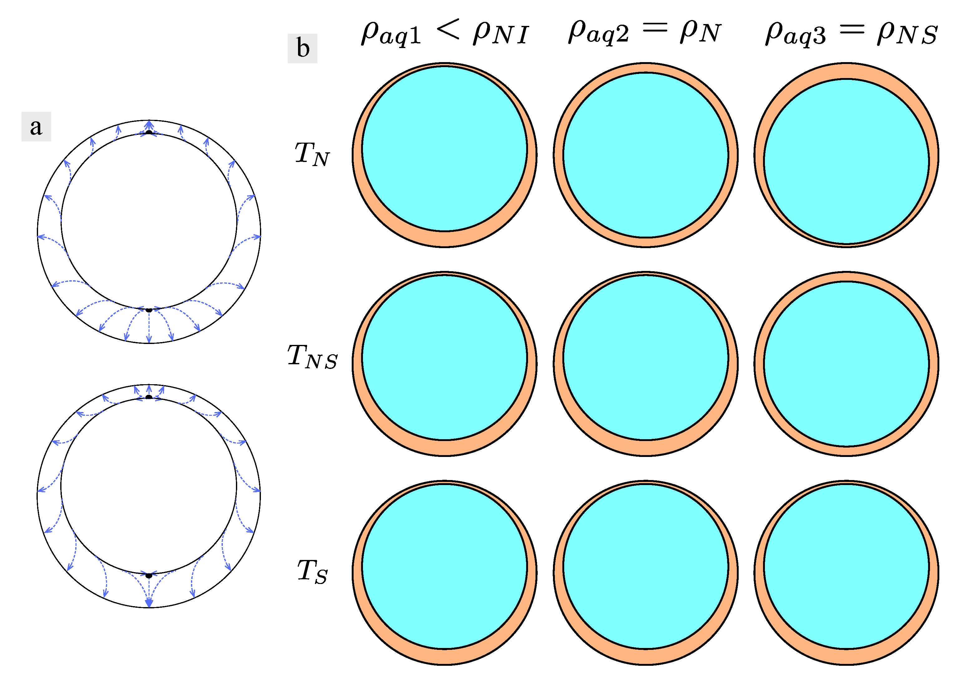
3.3. Cooling Shells with an Inner Phase That Is Density Matched to the LC in the N Phase, Observed Perpendicular and along Gravity

In the final experiment, we study shells where the inner aqueous phase has a density of ρ a q 2 , and is thus matched to ρ L C in the nematic phase. This means that the shells could be perfectly spherically symmetric, with the inner droplet concentric with the outer LC–aqueous interface, at high temperatures in the N phase, but as we cool towards T N S , ρ L C increases beyond ρ a q 2 and the inner droplet should float upwards, rendering the shells thin at the top and thick at the bottom, as viewed along gravity. To study this effect accurately, we initially tilted the microscope 90 ° , such that we observed the shells perpendicular to gravity.
As usual, we start out in the nematic phase, and we can indeed see predominantly spherically symmetric shells in Figure 5a,b, with relatively random orientations of the two +1 defects (they appear to remain antipodal, but the axis separating them has no particular orientation with respect to gravity). As we cool towards the phase transition, the LC becomes denser than the inner aqueous phase, and just above T N S , when the first stripe undulations are recognized in the nematic shells (c–d), all shells sink downwards within the capillary, and the inner droplet tends to move up within each shell. The reorientation is not perfect, but the majority of the shells have their thinnest point upwards as the FCDs of the SmA phase take over the texture in (e). Interestingly, these shells, with somewhat smaller diameter than those studied previously, become extremely thin at their thinnest point in the smectic phase, to the point that their thinnest point becomes ‘invisible’ between crossed polarizers, as clearly seen in two shells in the left half of Figure 5e.
We again heated up to the nematic phase, some shells still showing their extreme thin top in Figure 5f, but overall the shell asymmetry is reducing and in (g) all shells are clearly visible at all points. While the density matching in the nematic phase may be the main reason for the thinnest point becoming thicker again, it is difficult to believe that this is the sole explanation. After all, with density matched inner aqueous phase, there is no gravitational force acting on the inner droplet; hence, the shell ought to remain in the highly asymmetric configuration if no other forces act on the inner droplet. It thus seems that the SmA order, and most likely the diverging bend constant of the phase, promotes the extreme reduction in size of the thinnest point, whereas the nematic phase prefers a more symmetric shell configuration. In fact, although the interference color pattern in (g) shows that the shells are all oriented with the axis connecting the antipodal defects along gravity, the shells appear quite close to spherically symmetric in (g) and in (h).
It is now interesting to observe what happens when we bring the microscope back to the upright orientation, thus ‘rotating gravity’ back along the viewing direction in our experiments. The response to this change is shown in Figure 6. As the inner droplet is density matched to the LC at the time the microscope is reoriented, there is initially no driving force for the shells to reorient, and the texture remains largely the same as when the microscope was tilted. However, as we cool down close enough to T N S that the nematic stripe undulation starts, the shells find themselves in a non-equilibrium orientation, as now ρ L C > ρ a q 2 , and a collective reorientation can be seen in panels (a,b), until all shells face with their thinnest point upward in (c,d). We again tilted the microscope by 90 ° and this time all shells reoriented without delay, until we saw the stacked FCDs running uniformly along the vertical direction, from the thin top to the thick bottom, in almost all shells in panel (e,f).

4. Discussion

We end by discussing what might be the origin of the two most surprising observations described above, first considering the unexpected stable orientation of the shells with horizontal symmetry axis in Figure 4b–d,i,j. At this temperature, the inner aqueous droplet is density matched to the LC, as it appears in bulk. We speculate that the reason for the surprising stable equilibrium configuration is the free energy contribution of the very strong director field bend at the thinnest point of the shell, which may be enough to turn the LC to locally nematic at that point. Such a deformation-induced SmA-to-nematic transition has been suggested to occur at the core of SmA samples confined within a cylinder with normal boundary conditions [38], forcing the director to bend at the center in order to ‘escape in the third dimension’, as Meyer described it [39]. Since the elastic deformation cost of this bend would be prohibitive in the SmA phase, the LC develops a local nematic order along the cylinder core—i.e., T N S increases above the sample temperature where the bend is localized [38]. The same argument was put forward by Cladis and Torza for their initial attempt to describe the undulations seen near T N S in flat hybrid-aligned samples [10].
In our hybrid-aligned SmA shells, we have a similar situation at the thinnest point, and we thus argue that this point remains in a nematic state, as otherwise observed at higher temperatures. This also means that the density of the LC at this point is lower than in a bulk sample at the same temperature, i.e., ρ L C < ρ a q 3 at this point. Additionally, at the opposite end, the director bent around the other +1 defect may induce a smaller upward shift of T N S , with a corresponding slight reduction in ρ L C . We thus have two antipodal points with slightly lower ρ L C than that of the remainder of the shell, one with small reduction but in a larger volume, the other with larger reduction but in a very small volume. The effective buoyancy force may be similar on the two sides, which thus both strive upwards along gravity, the equilibrium configuration being when the two defects are approximately horizontal. We hope our empirical study and this plausible argument can stimulate further investigations, preferably supported by theory and computer simulations, as would be needed to test this hypothesis.
Next, we address the issue of why the interference color changes in the direction of increased Λ from the thickest to the thinnest point of the shell, when it is observed perpendicular to the symmetry axis, rather than the other way around. We believe the explanation is intimately related to the fact that the converging (hyperbolic) +1 defect resides in the thinnest point of the shell, and the diverging (radial) +1 defect resides at the thickest point, as indicated at the top of Figure 1a. If we observe the shell perpendicular to the symmetry axis, we are looking from left to right (or vice versa) in this drawing. Considering this, we may then note that, in the upper drawing, light passes largely along n ( r ) in the thickest part of the shell, while it traverses primarily perpendicular to n ( r ) in the thinnest part of the shell. Since n ( r ) gives the optic axis orientation of the LC, this means that we do not experience much birefringence in the thicker part of the shell, while we see nearly the complete birefringence near the thinnest point. Since Λ = d Δ n e f f , for the simple case of light traversing a birefringent material of thickness d and with uniform optic axis orientation giving it an effective birefringence Δ n e f f , we can have very low Λ even for large d, if Δ n e f f is low, as it is when we observe the sample nearly along the optic axis.
This qualitatively explains the observed interference color pattern. In fact, should the shells have adopted the opposite hybrid configuration, as at the bottom of Figure 1a, we should have seen almost no birefringence effect at all near the thinnest point, but a rapid succession of interference color orders towards the thickest point, as we then would have been observing mainly along the optic axis where the shell is thin, but perpendicular to the optic axis where it is thick. This is very different from the experimental observations, and we may thus conclude that all shells adopt the top configuration in Figure 1a. Again, this empirical argument should be corroborated in a future study with a complete computer simulation of the optics of the shell.

5. Conclusions and Outlook

Hybrid-aligned LC shells undergoing a transition from nematic to smectic-A phases constitute a highly interesting platform for studying the complex self-organization taking place in response to the spherical confinement. To approach equilibrium configurations, it is imperative to cool extremely slowly through the transition, explaining why the previous experiments of this type of shell did not reveal the same regular stacking of focal conic domains on the thin shell half as seen in this work. Moreover, the buoyancy driving the inner droplet up or down along gravity, or its absence at a particular temperature where the LC and the aqueous phase are density matched, significantly impacts the behavior. It appears, however, that the difficulty to accommodate the bend distortion imposed by the conflicting boundary conditions in the vicinity of T N S increases the shell asymmetry beyond what buoyancy would produce, most likely to induce a minimum volume around a thinnest point with a very tight bend, but where the phase remains nematic. This also affects the density in the vicinity of defects, being lower locally than in the remainder of the shell, giving rise to unexpected shell reorientations if the inner aqueous phase is density matched to the bulk LC at the N-SmA transition temperature. Computer simulations and theoretical analyses of the behavior of the LC near the N-SmA transition in shells would be highly beneficial in complementing the empirical data described here.

Author Contributions

Conceptualization, J.N. and J.P.F.L.; methodology, J.N.; formal analysis, J.P.F.L.; investigation, J.N.; resources, J.P.F.L.; data curation, J.N.; writing—original draft preparation, J.P.F.L.; writing—review and editing, J.P.F.L.; supervision, J.P.F.L.; project administration, J.N. and J.P.F.L.; funding acquisition, J.N. and J.P.F.L. All authors have read and agreed to the published version of the manuscript.

Funding

This research was funded by the European Research Council under the European Union’s H2020 Programme/ERC Grant Agreement No. 648763 (consolidator project INTERACT) and the Fonds National de la recherche Luxembourg (J.N., grant ID 6992111).

Data Availability Statement

The data presented in this study are available on reasonable request from the corresponding author.

Conflicts of Interest

The authors declare no conflict of interest.

References

  1. de Gennes, P.G.; Prost, J. The Physics of Liquid Crystals; Clarendon Press: Oxford, UK, 1993. [Google Scholar]
  2. Kleman, M.; Lavrentovich, O.D. Soft Matter Physics: An Introduction; Springer: Berlin/Heidelberg, Germany, 2002. [Google Scholar]
  3. Allender, D.W.; Hornreich, R.; Johnson, D. Theory of the stripe phase in bend-Freedericksz-geometry nematic films. Phys. Rev. Lett. 1987, 59, 2654. [Google Scholar] [CrossRef]
  4. Pergamenshchik, V. Surfacelike-elasticity-induced spontaneous twist deformations and long-wavelength stripe domains in a hybrid nematic layer. Phys. Rev. E 1993, 47, 1881. [Google Scholar] [CrossRef]
  5. Sparavigna, A.; Lavrentovich, O.; Strigazzi, A. Periodic stripe domains and hybrid-alignment regime in nematic liquid crystals: Threshold analysis. Phys. Rev. E 1994, 49, 1344. [Google Scholar] [CrossRef] [PubMed] [Green Version]
  6. Lavrentovich, O.; Pergamenshchik, V. Stripe domain phase of a thin nematic film and the K 13 divergence term. Phys. Rev. Lett. 1994, 73, 979. [Google Scholar] [CrossRef] [Green Version]
  7. Lavrentovich, O.; Pergamenshchik, V. Patterns in thin liquid crystal films and the divergence (“surfacelike”) elasticity. In Liquid Crystals in the Nineties and Beyond; World Scientific: Singapore, 1995; pp. 251–299. [Google Scholar]
  8. Krzyzański, D.; Derfel, G. Structure of spontaneous periodic deformations in hybrid aligned nematic layers. Phys. Rev. E 2001, 63, 021702. [Google Scholar] [CrossRef]
  9. Barbero, G.; Pergamenshchik, V. Intermediate periodic “saddle-splay” nematic phase in the vicinity of a nematic-smectic-A transition. Phys. Rev. E 2002, 66, 051706. [Google Scholar] [CrossRef] [PubMed]
  10. Cladis, P.; Torza, S. Growth of a smectic-A from a bent nematic phase and smectic light valve. J. Appl. Phys. 1975, 46, 584–599. [Google Scholar] [CrossRef]
  11. Pergamenshchik, V.; Lelidis, I.; Uzunova, V. Stripe domains in a nearly homeotropic nematic liquid crystal: A bend escaped state at a nematic-smectic-A transition. Phys. Rev. E 2008, 77, 041703. [Google Scholar] [CrossRef]
  12. Zappone, B.; Lacaze, E. Surface-frustrated periodic textures of smectic-A liquid crystals on crystalline surfaces. Phys. Rev. E 2008, 78. [Google Scholar] [CrossRef]
  13. Delabre, U.; Richard, C.; Cazabat, A. Thin Nematic Films on Liquid Substrates (dagger). J. Phys. Chem. B 2008, 113, 3647–3652. [Google Scholar] [CrossRef] [Green Version]
  14. Gim, M.; Beller, D.; Yoon, D. Morphogenesis of liquid crystal topological defects during the nematic-smectic A phase transition. Nat. Commun. 2017, 8, 15453. [Google Scholar] [CrossRef] [Green Version]
  15. Meyer, C.; Cunff, L.; Belloul, M. Focal Conic Stacking in Smectic A Liquid Crystals: Smectic Flower and Apollonius Tiling. Materials 2009, 2, 499. [Google Scholar] [CrossRef] [Green Version]
  16. Beller, D.; Gharbi, M.; Honglawan, A.; Stebe, K.; Yang, S.; Kamien, R. Focal Conic Flower Textures at Curved Interfaces. Phys. Rev. X 2013, 3, 041026. [Google Scholar] [CrossRef] [Green Version]
  17. Bouligand, Y. Recherches sur les textures des états mésomorphes-1. Les arrangements focaux dans les smectiques: Rappels et considérations théoriques. J. Phys. 1972, 33, 525–547. [Google Scholar] [CrossRef]
  18. Kléman, M.; Lavrentovich, O.D. Grain boundaries and the law of corresponding cones in smectics. Eur. Phys. J. E 2000, 2, 47–57. [Google Scholar] [CrossRef]
  19. Kleman, M.; Meyer, C.; Nastishin, Y.A. Imperfections in focal conic domains: The role of dislocations. Philos. Mag. 2006, 86, 4439–4458. [Google Scholar] [CrossRef] [Green Version]
  20. Kleman, M.; Lavrentovich, O.D. Liquids with conics. Liq. Cryst. 2009, 36, 1085–1099. [Google Scholar] [CrossRef]
  21. Yoon, D.; Choi, M.; Kim, Y.; Kim, M.; Lavrentovich, O.; Jung, H. Internal structure visualization and lithographic use of periodic toroidal holes in liquid crystals. Nat. Mater. 2007, 6, 866–870. [Google Scholar] [CrossRef]
  22. Zappone, B.; Meyer, C.; Bruno, L.; Lacaze, E. Periodic lattices of frustrated focal conic defect domains in smectic liquid crystal films. Soft Matter 2012, 8, 4318–4326. [Google Scholar] [CrossRef]
  23. Ok, J.M.; Kim, Y.H.; Jeong, H.S.; Yoo, H.W.; Kim, J.H.; Srinivasarao, M.; Jung, H.T. Control of periodic defect arrays of 8CB (4’-n-octyl-4-cyano-biphenyl) liquid crystals by multi-directional rubbing. Soft Matter 2013, 9, 10135. [Google Scholar] [CrossRef]
  24. Honglawan, A.; Beller, D.A.; Cavallaro, M.; Kamien, R.D.; Stebe, K.J.; Yang, S. Topographically induced hierarchical assembly and geometrical transformation of focal conic domain arrays in smectic liquid crystals. Proc. Natl. Acad. Sci. USA 2013, 110, 34–39. [Google Scholar] [CrossRef] [Green Version]
  25. Kim, Y.H.; Lee, J.O.; Jeong, H.S.; Kim, J.H.; Yoon, E.K.; Yoon, D.K.; Yoon, J.B.; Jung, H.T. Optically Selective Microlens Photomasks Using Self-Assembled Smectic Liquid Crystal Defect Arrays. Adv. Mater. 2010, 22, 2416. [Google Scholar] [CrossRef] [PubMed]
  26. Serra, F.; Gharbi, M.A.; Luo, Y.; Liu, I.B.; Bade, N.D.; Kamien, R.D.; Yang, S.; Stebe, K.J. Curvature-Driven, One-Step Assembly of Reconfigurable Smectic Liquid Crystal “Compound Eye” Lenses. Adv. Opt. Mater. 2015, 3, 1287–1292. [Google Scholar] [CrossRef] [Green Version]
  27. Lopez-Leon, T.; Fernandez-Nieves, A. Drops and shells of liquid crystal. Colloid Polym. Sci. 2011, 289, 345–359. [Google Scholar] [CrossRef]
  28. Urbanski, M.; Reyes, C.G.; Noh, J.; Sharma, A.; Geng, Y.; Jampani, V.S.R.; Lagerwall, J.P. Liquid crystals in micron-scale droplets, shells and fibers. J. Phys. Condens. Matter 2017, 29, 133003. [Google Scholar] [CrossRef] [PubMed] [Green Version]
  29. Lopez-Leon, T.; Fernandez-Nieves, A. Topological transformations in bipolar shells of nematic liquid crystals. Phys. Rev. E 2009, 79, 021707. [Google Scholar] [CrossRef]
  30. Noh, J.; Reguengo De Sousa, K.; Lagerwall, J.P.F. Influence of interface stabilisers and surrounding aqueous phases on nematic liquid crystal shells. Soft Matter 2016, 12, 367–372. [Google Scholar] [CrossRef] [PubMed]
  31. Noh, J.; Wang, Y.; Liang, H.L.; Jampani, V.S.R.; Majumdar, A.; Lagerwall, J.P.F. Dynamic tuning of the director field in liquid crystal shells using block copolymers. Phys. Rev. Res. 2020, 2, 033160. [Google Scholar] [CrossRef]
  32. Sharma, A.; Lagerwall, J.P.F. Influence of head group and chain length of surfactants used for stabilising liquid crystal shells. Liq. Cryst. 2018, 45, 2319–2328. [Google Scholar] [CrossRef]
  33. Liang, H.L.; Zentel, R.; Rudquist, P.; Lagerwall, J. Towards tunable defect arrangements in smectic liquid crystal shells utilizing the nematic-smectic transition in hybrid-aligned geometries. Soft Matter 2012, 8, 5443–5450. [Google Scholar] [CrossRef] [Green Version]
  34. Liang, H.; Noh, J.; Zentel, R.; Rudquist, P.; Lagerwall, J. Tuning the defect configurations in nematic and smectic liquid crystalline shells. Philos. Transact. A Math. Phys. Eng. Sci. 2013, 371, 20120258. [Google Scholar] [CrossRef] [PubMed]
  35. Utada, A.; Lorenceau, E.; Link, D.R.; Kaplan, P.D.; Stone, H.A.; Weitz, D.A. Monodisperse double emulsions generated from a microcapillary device. Science 2005, 308, 537–541. [Google Scholar] [CrossRef] [PubMed] [Green Version]
  36. Noh, J.; Henx, B.; Lagerwall, J.P. Taming Liquid Crystal Self-Assembly: The Multifaceted Response of Nematic and Smectic Shells to Polymerization. Adv. Mater. 2016, 28, 10170–10174. [Google Scholar] [CrossRef] [Green Version]
  37. Sandmann, M.; Würflinger, A. PVT measurements on 4?-n-octyl-biphenyl-4-carbonitrile (8CB) up to 300 MPa. Zeitschrift für Naturforschung A 1998, 53, 787–792. [Google Scholar] [CrossRef]
  38. Kralj, S.; Zumer, S. Smectic-A structures in submicrometer cylindrical cavities. Phys. Rev. E 1996, 54, 1610–1617. [Google Scholar] [CrossRef] [Green Version]
  39. Meyer, R.B. On the existence of even indexed disclinations in nematic liquid crystals. Philos. Mag. 1973, 27, 405–424. [Google Scholar] [CrossRef]
Figure 1. Schematic drawings of LC shell cross sections containing the main symmetry axis, typically running between the antipodal thinnest and thickest points. (a) In an asymmetric shell with tangential internal and normal external boundary, n ( r ) can take two types of hybrid configuration: with a convergent +1 defect at the thinnest point and a divergent +1 defect at the thickest point (top), or vice versa (bottom). (b) The expected equilibrium geometry, as viewed perpendicular to gravity, at temperatures near the N-isotropic transition (top), near the N-SmA transition (middle) and in the SmA phase (bottom), for an internal aqueous phase that is density matched to the LC in the isotropic state (left), in the nematic state (middle) and at the N-SmA transition (right), respectively. The LC phase is drawn in orange, the inner aqueous phase in cyan.
Crystals 11 00913 g001
Figure 2. Polarizing microscopy photos of an LC shell, observed along gravity, with an inner droplet of ordinary water, with density lower than that of the LC throughout the N and SmA temperature ranges. The sequence is obtained on cooling from N to SmA, the latter being fully developed in (hj). The focus is at the top of the shell except in (f,j), where the focus is at the bottom and equator, respectively. Photos (ah) were obtained through crossed polarizers (orientation indicated in (a)), a λ -plate inserted in (c) with its slow axis as indicated, and photos (i,j) were obtained with a polarizer but not analyzer. Scale bar represents 100 μ m in the focal plane.
Crystals 11 00913 g002
Figure 3. High-magnification polarizing microscopy photos of an LC shell, observed along gravity at constant temperature in the SmA phase, about 0.1 K below T N S . The LC density is greater than that of the inner aqueous phase, yielding a thin top. The focus is at the top (a,d), equator (b,e) and bottom (c,f), respectively. Photos (ac) were obtained between crossed polarizers (cross in (a), whereas (df) were obtained without an analyzer. Scale bar represents 100 μ m in the focal plane.
Crystals 11 00913 g003
Figure 4. Polarizing microscopy photos of shells (diameter ∼145 μ m), observed along gravity, with an inner aqueous phase density matched to the LC at the N-SmA transition, upon cooling from the nematic phase (ad) into the SmA phase (eh) and then heating back up through the transition (i) and into the nematic phase again (j). Photos (a,b,d,j) were obtained through crossed polarizers (indicated in a) while the others were obtained without an analyzer. Shell numbering in (c,d) is to identify the same shells in each image, as the shells moved somewhat between the photos. Scale bar represents 100 μ m in the focal plane.
Crystals 11 00913 g004
Figure 5. Polarizing microscopy photos of shells (diameter ∼125 μ m), observed perpendicular to gravity (microscope tilted 90 ° ; gravity is directed downwards in the images), with an inner aqueous phase density matched to the LC in the N phase, upon cooling from the nematic phase (ad) into the SmA phase (e) and then heating back up into the nematic phase again (fh). Photos (b,dg) were obtained through crossed polarizers (indicated in b), while the others were obtained without the analyzer. Scale bar represents 100 μ m in the focal plane.
Crystals 11 00913 g005
Figure 6. Polarizing microscopy photos of the same shells as in Figure 5 just after the microscope was brought back to upright orientation while the shells were in the nematic phase (a), where the LC and inner aqueous phase are density matched. Upon cooling into the SmA phase, the LC becomes denser than the inner aqueous phase and the shells thus reorient (or the inner droplet relocates within the shell) until the thinnest point faces upwards (bd). The microscope has again been tilted 90 ° in (e,f), and we have waited until the shells have almost reoriented in response to the change in gravitational force direction (directed downward in these photos); hence, we see the shells from the side, with the thin top upwards and the thick bottom downward. Photo (e) was obtained without an analyzer, all others between crossed polarizers (indicated in a); photo (d) additionally has a λ -plate inserted, its slow axis oriented as indicated. Scale bar represents 100 μ m in the focal plane.
Crystals 11 00913 g006
Publisher’s Note: MDPI stays neutral with regard to jurisdictional claims in published maps and institutional affiliations.

