
Local Buckling Behavior of Buckling-Restrained Braces with Longitudinally Profiled Steel Core

Abstract
:
1. Introduction
2. Concept of LPBRB, Experimental Results and Finite Element Model
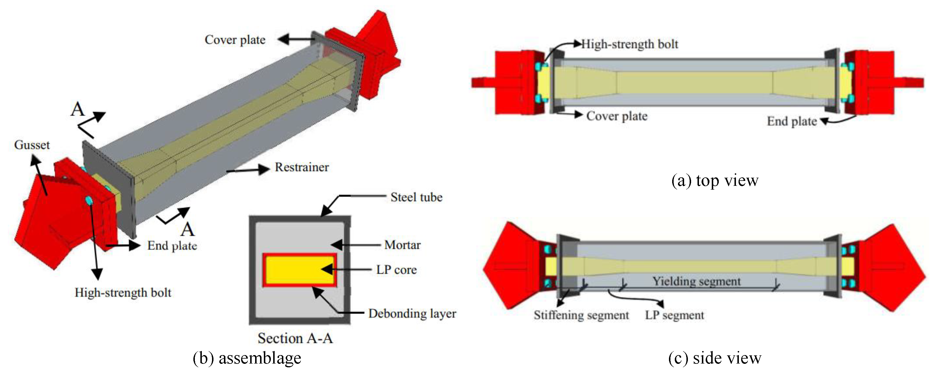
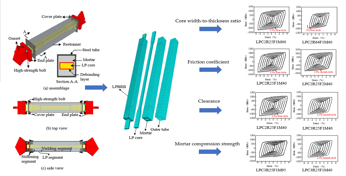
2.1. Concept of LPBRB
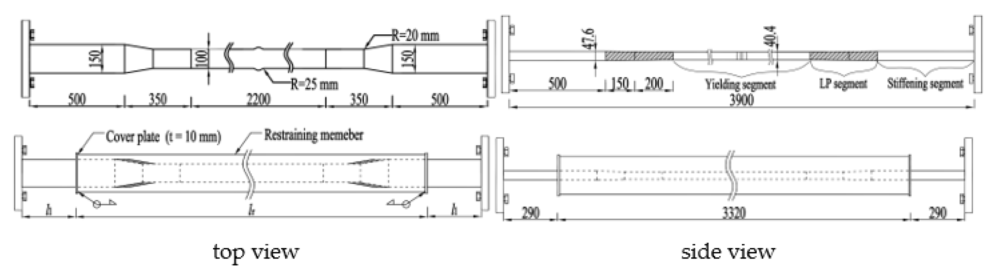
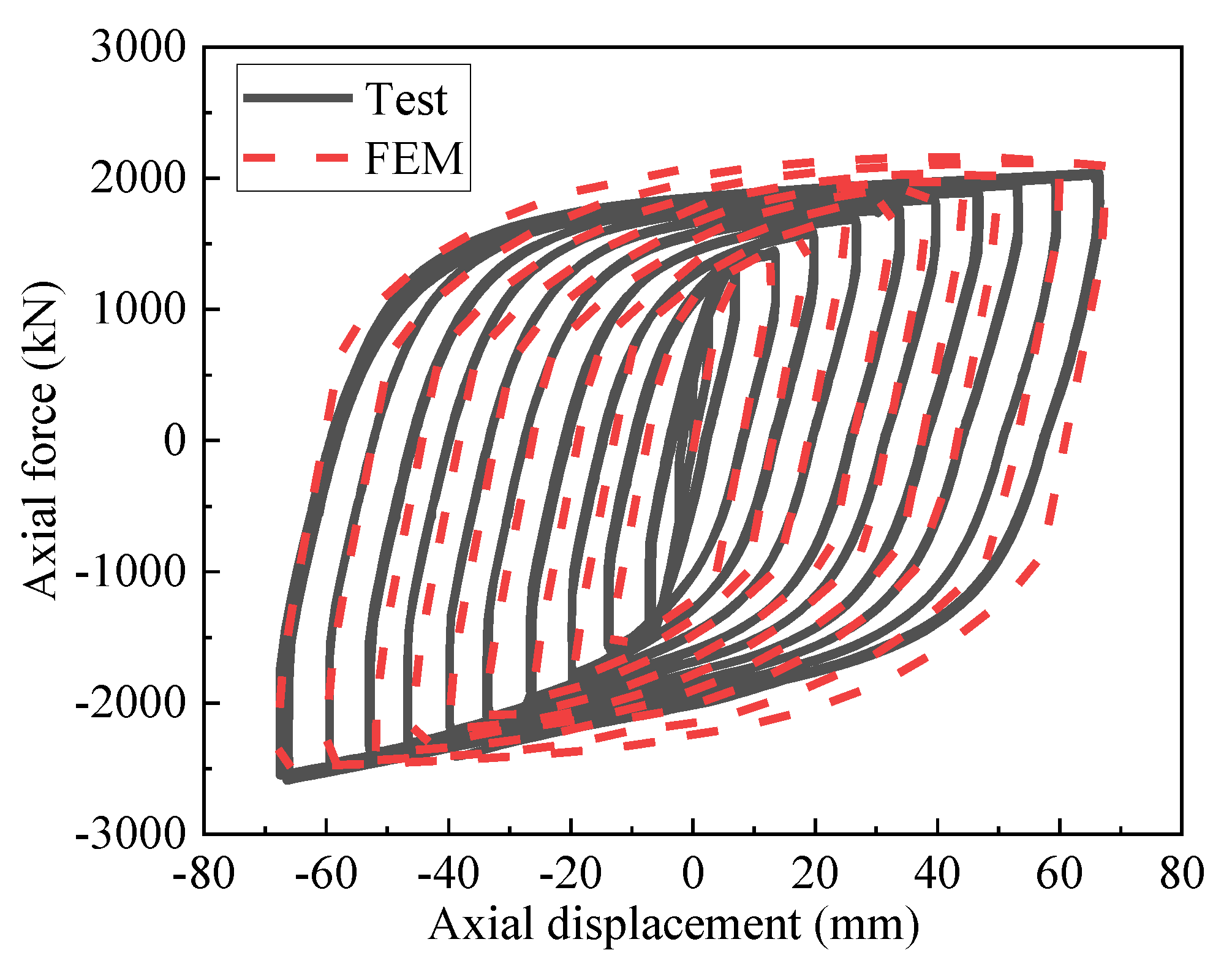
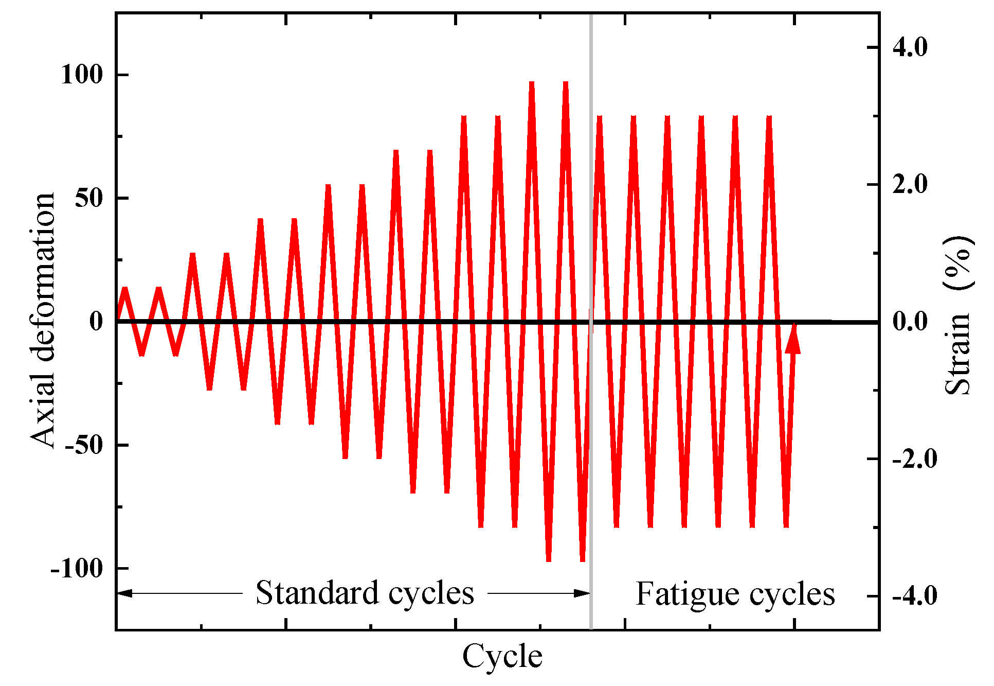
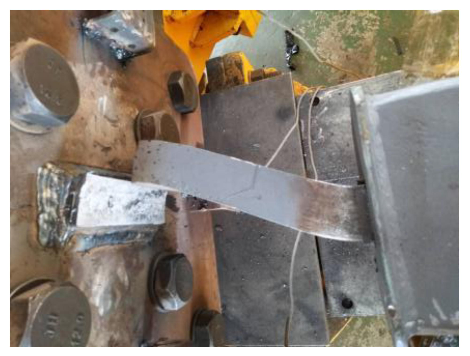
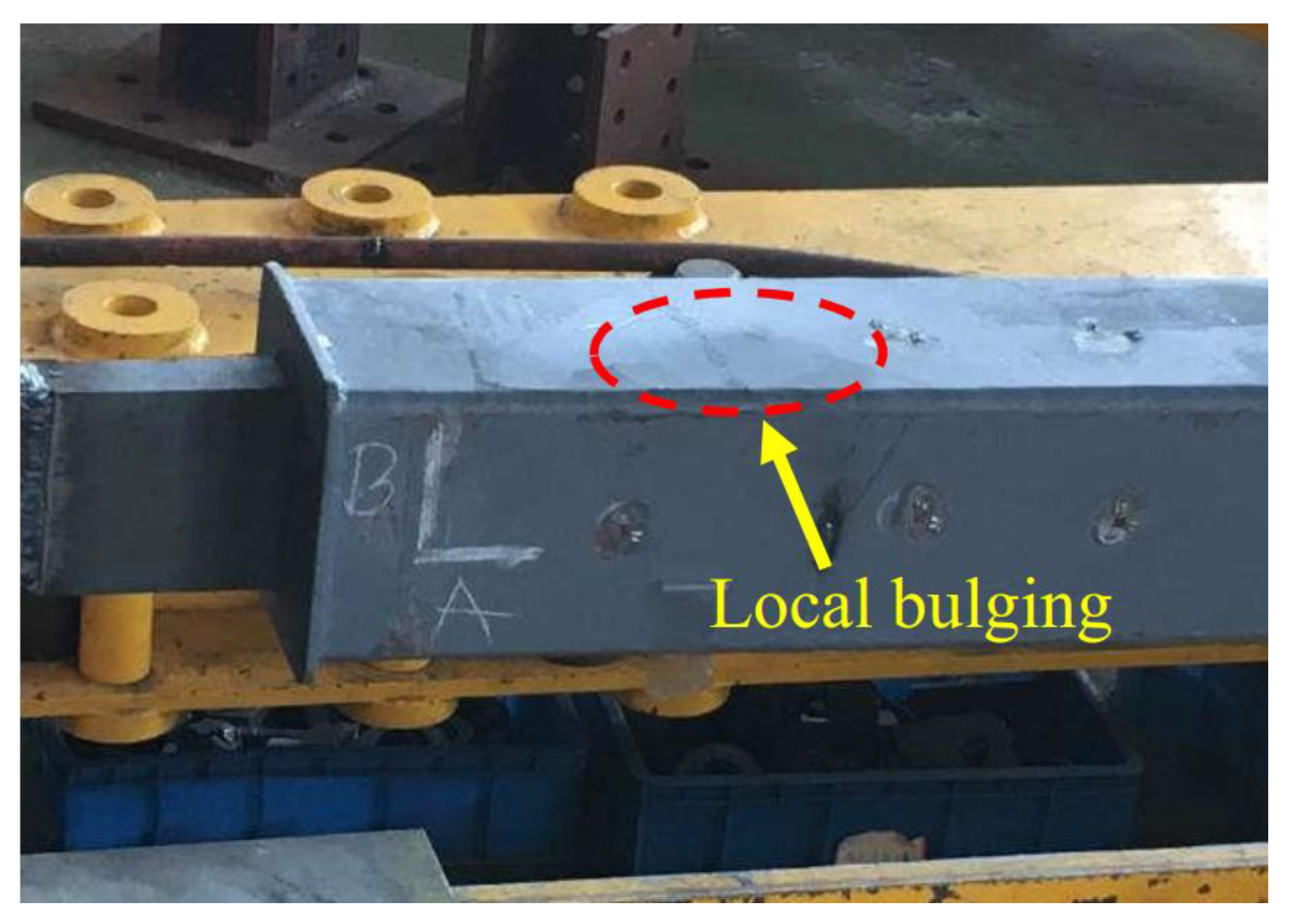
2.2. LPBRB Experimental Result
2.3. LPBRB Model Description
3. Results and Discussions
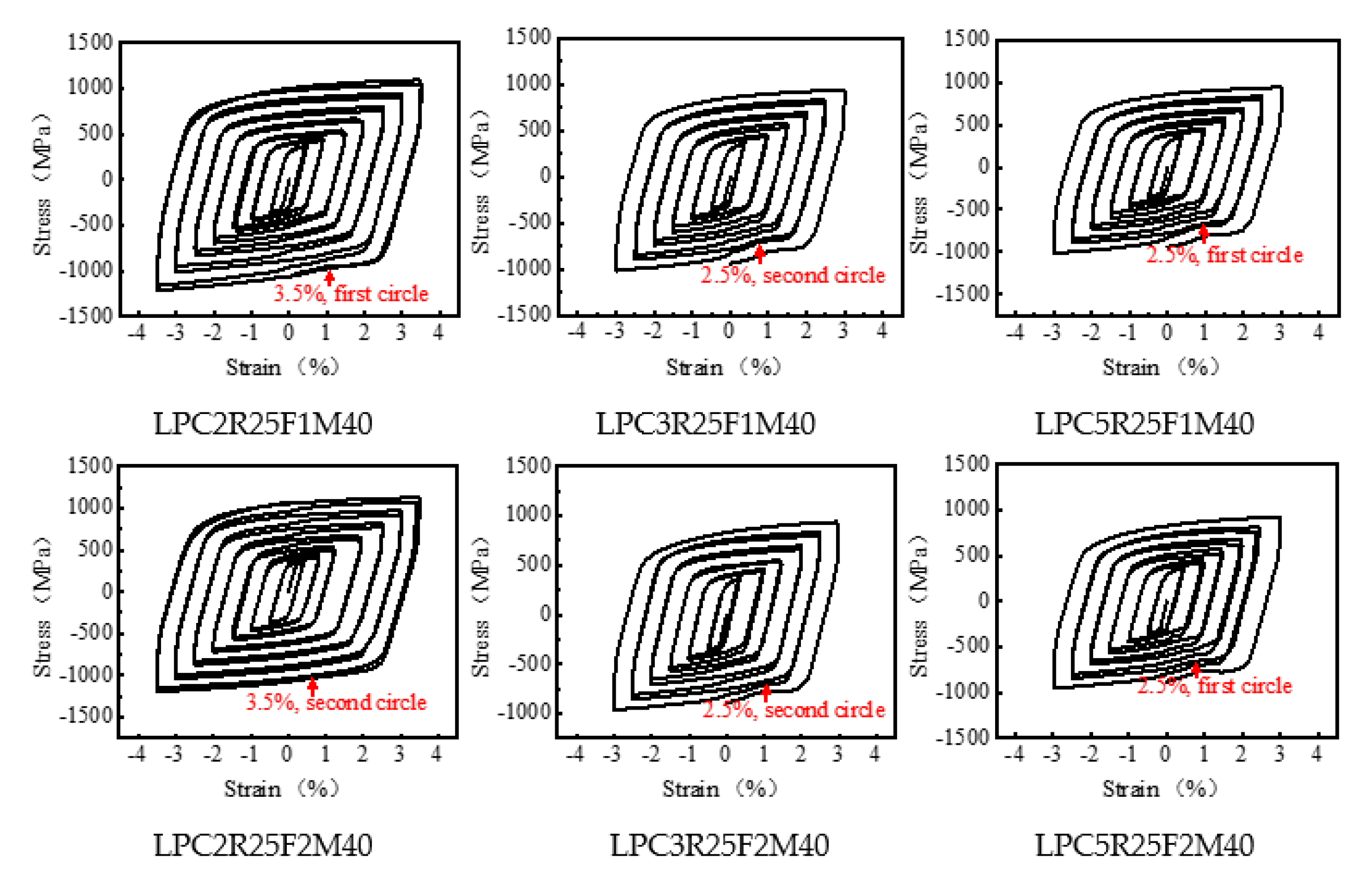
3.1. Effect of Clearance between the LP Core and the Restraining Member
3.2. Effect of Friction Coefficient
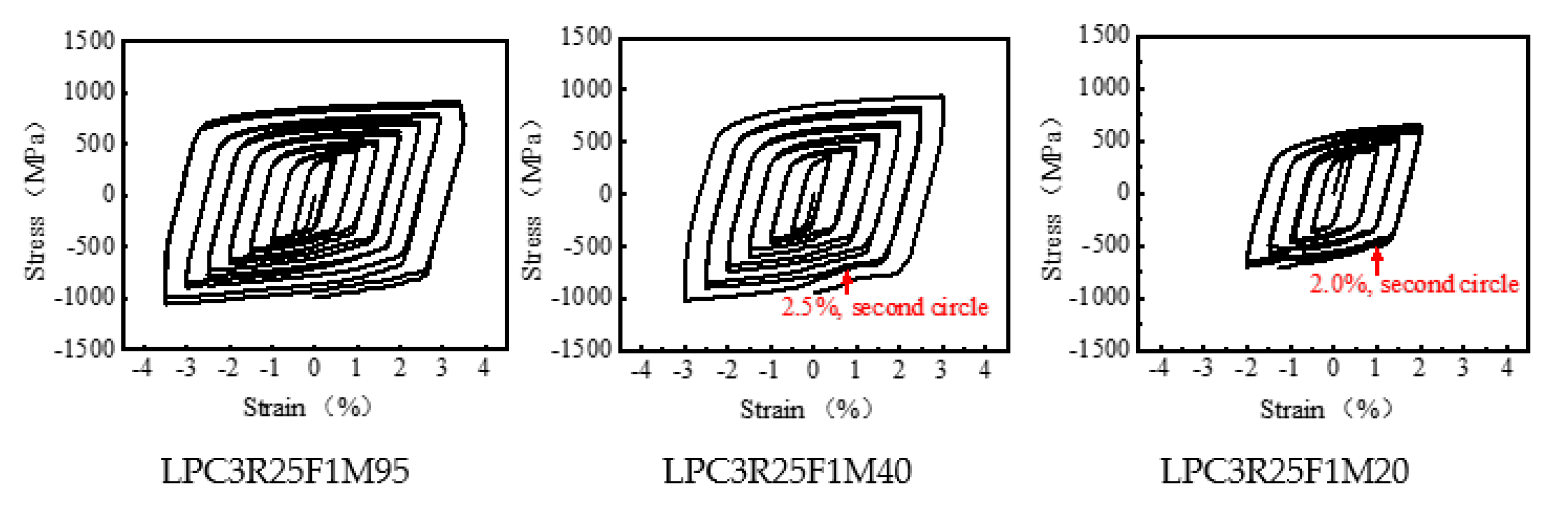
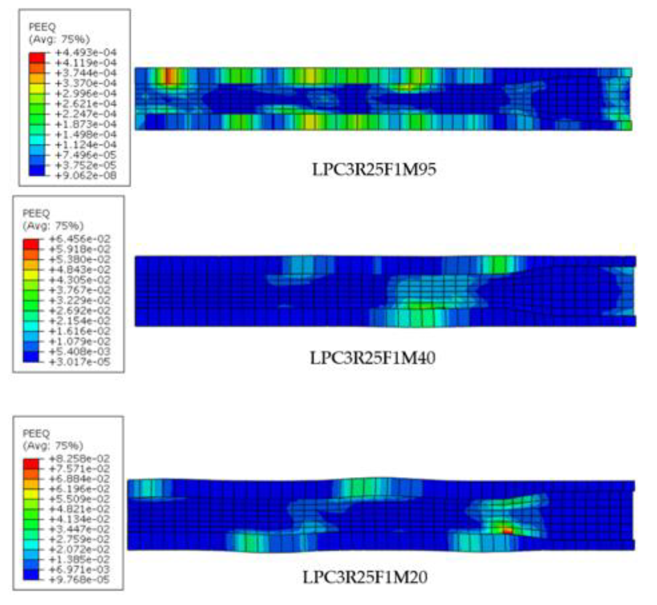
3.3. Effect of Mortar Strength in Preventing Local Buckling Failure
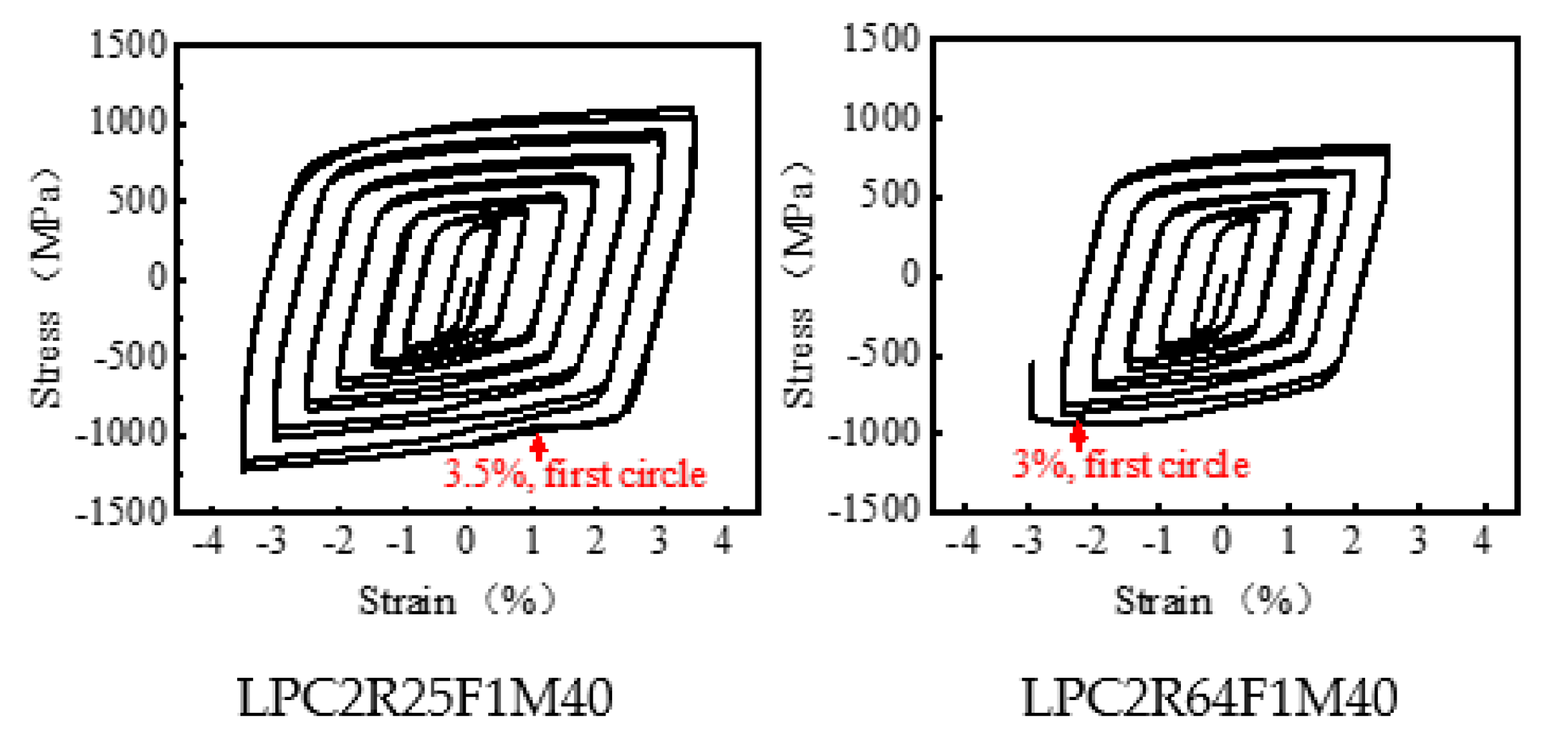
3.4. Effect of Width-to-Thickness Ratio of LP Core
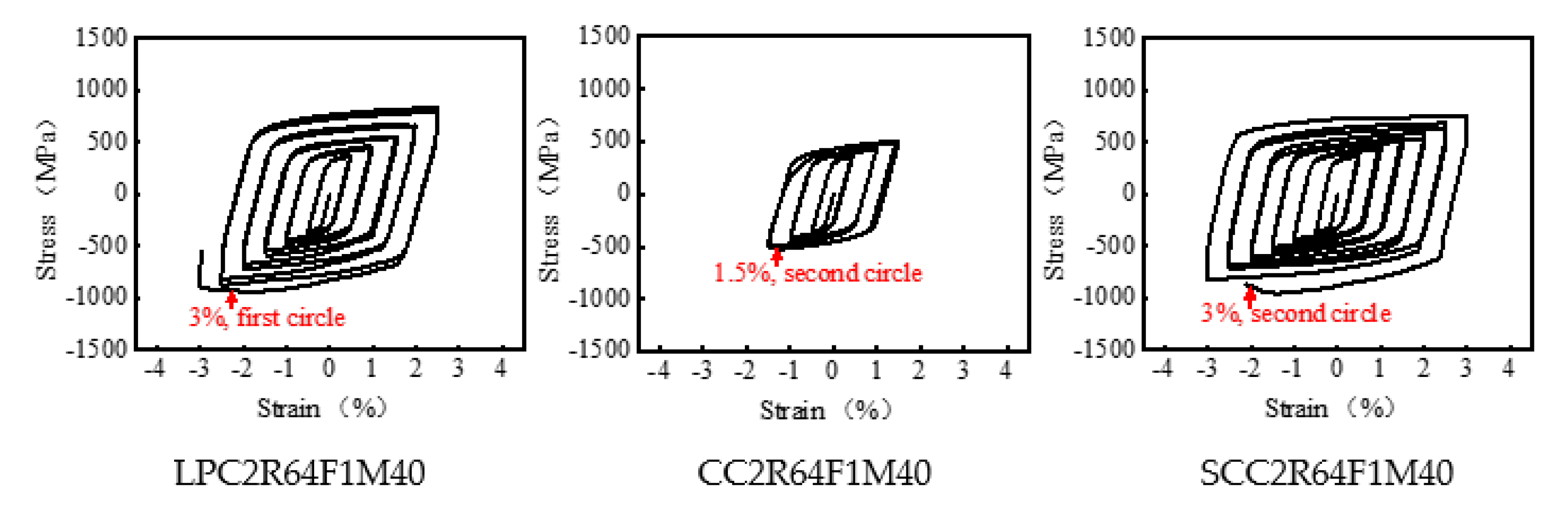
3.5. Comparison of LPBRBs and BRBs with the Constant-Thickness Steel Core
4. Conclusions
Author Contributions
Funding
Data Availability Statement
Acknowledgments
Conflicts of Interest
References
- Chou, C.C.; Chung, P.T. Development of cross-anchored dual-core self-centering braces for seismic resistance. J. Constr. Steel Res. 2014, 101, 19–32. [Google Scholar] [CrossRef]
- Tsai, C.Y.; Tsai, K.C.; Chen, L.W.; Wu, A.C. Seismic performance analysis of BRBs and gussets in a full-scale 2-story BRB-RCF specimen. Earthq. Eng. Struct. Dyn. 2018, 47, 2366–2389. [Google Scholar] [CrossRef]
- Jia, L.J.; Ge, H.B.; Xiang, P.; Liu, Y. Seismic performance of fish-bone shaped buckling-restrained braces with controlled damage process. Eng. Struct. 2018, 169, 141–153. [Google Scholar] [CrossRef]
- Wang, C.L.; Chen, Q.; Zeng, B.; Meng, S.P. A novel brace with partial buckling restraint: An experimental and numerical investigation. Eng. Struct. 2017, 150, 190–202. [Google Scholar] [CrossRef]
- Zhao, J.X.; Wu, B.; Ou, J.P. A practical and unified global stability design method of buckling-restrained braces: Discussion on pinned connections. J. Constr. Steel Res. 2014, 95, 106–115. [Google Scholar] [CrossRef]
- Lu, J.K.; Wu, B.; Mei, Y. Buckling mechanism of steel core and global stability design method for fixed-end buckling-restrained braces. Eng. Struct. 2018, 174, 447–461. [Google Scholar] [CrossRef]
- Wu, B.; Lu, J.K.; Mei, Y.; Zhang, J. Buckling mechanism and global stability design method of buckling-restrained braces. J. Constr. Steel Res. 2017, 138, 473–487. [Google Scholar] [CrossRef]
- Tremblay, R.; Bolduc, P.; Neville, R.; Devall, R. Seismic Testing and Performance of Buckling-Restrained Bracing Systems. Can. J. Civ. Eng. 2006, 33, 183–198. [Google Scholar] [CrossRef]
- Aniello, M.; Corte, G.; Landolfo, R. Finite element modelling and analysis of “all-steel” dismountable buckling-restrained braces. Open Constr. Build. Technol. J. 2014, 8 (Suppl. 1: M4), 216–226. [Google Scholar]
- Rahnavard, R.; Naghavi, M.; Aboudi, M.; Suleiman, M. Investigating modeling approaches of buckling-restrained braces under cyclic loads. Case Stud. Constr. Mater. 2018, 8, 476–488. [Google Scholar] [CrossRef]
- Naghavi, M.; Rahnavard, R.; Thomas, R.J.; Malekinejad, M. Numerical evaluation of the hysteretic behavior of concentrically braced frames and buckling restrained brace frame systems. J. Build. Eng. 2019, 22, 415–428. [Google Scholar] [CrossRef]
- Rahnavard, R.; Rebelo, C.; Craveiro, H.; Napolitano, R. Numerical investigation of the cyclic performance of reinforced concrete frames equipped with a combination of a rubber core and a U-shaped metallic damper. Eng. Struct. 2020, 225, 111307. [Google Scholar] [CrossRef]
- Rahnavard, R.; Rebelo, C.; Craveiro, H.; Napolitano, R. Understanding the cyclic performance of composite steel-concrete connections on steel bridges. Eng. Struct. 2020, 224, 111213. [Google Scholar] [CrossRef]
- Genna, F.; Gelfi, P. Analysis of the lateral thrust in bolted steel buckling-restrained braces. Part 1: Experimental and numerical results. J. Struct. Eng. 2012, 138, 1231–1243. [Google Scholar] [CrossRef]
- Takeuchi, T.; Hajjar, J.F.; Matsui, R. Local buckling restraint condition for core plates in buckling restrained braces. J. Constr. Steel Res. 2010, 66, 139–149. [Google Scholar] [CrossRef]
- Takeuchi, T.; Hajjar, J.F.; Matsui, R.; Nishimoto, K.; Alike, I.D. Effect of local buckling core plate restraint in buckling restrained braces. Eng. Struct. 2012, 44, 304–311. [Google Scholar] [CrossRef]
- Lin, P.C.; Tsai, K.C.; Chang, C.A.; Hsiao, Y.Y.; Wu, A.C. Seismic design and testing of buckling-restrained braces with a thin profile. Earthq. Eng. Struct. Dyn. 2016, 45, 339–358. [Google Scholar] [CrossRef]
- Lin, P.C.; Tsai, K.C.; Wang, K.J. Seismic design and hybrid tests of a full-scale three-story buckling-restrained braced frame using welded end connections and thin profile. Earthq. Eng. Struct. Dyn. 2012, 41, 1001–1020. [Google Scholar] [CrossRef]
- Wang, C.L.; Usami, T.; Funayama, J. Improving low-cycle fatigue performance of high-performance buckling-restrained braces by toe-finished method. Earthq. Eng. 2012, 16, 1248–1268. [Google Scholar] [CrossRef]
- Matsui, R.; Takeuchi, T. Cumulative deformation capacity of buckling restrained braces taking local buckling of core plates into account. In Proceedings of the 15th World Conference on Earthquake Engineering, Lisbon, Portugal, 24–28 September 2012. [Google Scholar]
- Wang, C.L.; Zhao, J.; Gao, Y.; Meng, S.P. Experimental investigation of modular buckling-restrained energy dissipaters with detachable features. J. Constr. Steel Res. 2020, 172, 106191. [Google Scholar] [CrossRef]
- Liu, X.H. Prospects for variable gauge rolling: Technology, theory and application. J. Iron Steel Res. Int. 2011, 18, 1–7. [Google Scholar] [CrossRef]
- Fukumoto, Y.; Takaku, T.; Aoki, T.; Susantha, K. Innovative Use of Profiled Steel Plates for Seismic Structural Performance. Adv. Struct. Eng. 2005, 8, 247–257. [Google Scholar] [CrossRef]
- Lu, J.K. Stability Design Methods and Tests of Buckling-Restrained Braces and Gusset Plates. Ph.D. Thesis, Harbin Institute of Technology, Harbin, China, 2017. (In Chinese). [Google Scholar]
- Brozzetti, J. Design development of steel-concrete bridges in France. J. Constr. Steel Res. 2000, 55, 229–243. [Google Scholar] [CrossRef]
- Takaku, T.; Fukumoto, Y.; Aoki, T. Seismic design of bridge piers with stiffened square box columns with thickness tapered plates. In Proceedings of the 13th World Conference on Earthquake Engineering, Vancouver, Canada, 1–6 August 2004; p. 3224. [Google Scholar]
- Li, Y.Y. Investigation on the Design Method and the Seismic Performance for the BRBs with Longitudinally Profiled Steel Plate as Inner-Core. Master’s Thesis, Harbin Institute of Technology, Harbin, China, 2017. (In Chinese). [Google Scholar]
- ABAQUS/Standard, Version 6.20; ABAQUS Inc.: Pawtucket, RI, USA, 2020.
- Hoveidae, N.; Rafezy, B. Local Buckling Behavior of Core Plate in All-Steel Buckling Restrained Braces. Int. J. Steel Struct. 2015, 15, 249–260. [Google Scholar] [CrossRef]
- American Institute of Steel Construction. AISC 341-10: Seismic Provisions for Structural Steel Buildings; American Institute of Steel Construction: Chicago, IL, USA, 2010. [Google Scholar]


| No. | Model | LP Core Dimensions(mm) | C (mm) | Mortar Compression Strength (MPa) | μ | Core Width-Thickness Ratio |
|---|---|---|---|---|---|---|
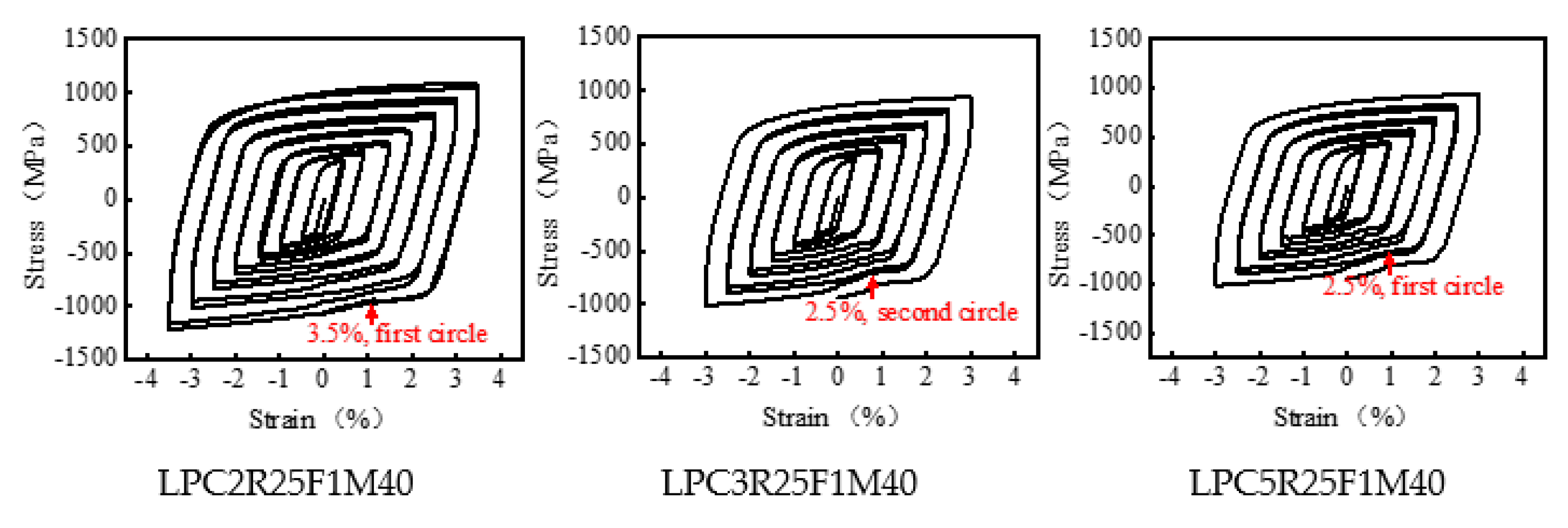
| 1 | LPC2R25F1M40 | 48 × 150/40 × 100 | 2 | 40 | 0.3 | 2.5 |
| 2 | LPC3R25F1M40 | 48 × 150/40 × 100 | 3 | 40 | 0.3 | 2.5 |
| 3 | LPC5R25F1M40 | 48 × 150/40 × 100 | 5 | 40 | 0.3 | 2.5 |
| 4 | LPC2R25F2M40 | 48 × 150/40 × 100 | 2 | 40 | 0.1 | 2.5 |
| 5 | LPC3R25F2M40 | 48 × 150/40 × 100 | 3 | 40 | 0.1 | 2.5 |
| 6 | LPC5R25F2M40 | 48 × 150/40 × 100 | 5 | 40 | 0.1 | 2.5 |
| 7 | LPC2R64F1M40 | 33 × 210/25 × 160 | 2 | 40 | 0.3 | 6.4 |
| 8 | LPC3R25F1M20 | 48 × 150/40 × 100 | 3 | 20 | 0.3 | 2.5 |
| 9 | LPC3R25F1M95 | 48 × 150/40 × 100 | 3 | 95 | 0.3 | 2.5 |
| 10 | CC2R64F1M40 | 25 × 210/25 × 160 | 2 | 40 | 0.3 | 6.4 |
| 11 | SCC2R64F1M40 | 25 × 210/25 × 160 | 2 | 40 | 0.3 | 6.4 |
| fy | Q∞ | b | C1 | γ1 | C2 | γ2 | C3 | γ3 |
|---|---|---|---|---|---|---|---|---|
| 290 | 680 | 1.44 | 8000 | 100 | 90,000 | 2400 | 1200 | 0 |
| ψ | ϵ | σb0/σc0 | K | μ |
|---|---|---|---|---|
| 20 | 0.1 | 1.16 | 0.6667 | 0.0005 |
| No. | Model | LP Core Dimensions (mm) | β | μ | DCR | CPD |
|---|---|---|---|---|---|---|
| 1 | LPC2R25F1M40 | 48 × 150/40 × 100 | 1.07 | 0.3 | 1.01 | 546 |
| 2 | LPC3R25F1M40 | 48 × 150/40 × 100 | 1.09 | 0.3 | 1.38 | 465 |
| 3 | LPC5R25F1M40 | 48 × 150/40 × 100 | 1.06 | 0.3 | 2.11 | 384 |
| 4 | LPC2R25F2M40 | 48 × 150/40 × 100 | 1.06 | 0.1 | 1.05 | 641 |
| 5 | LPC3R25F2M40 | 48 × 150/40 × 100 | 1.03 | 0.1 | 1.12 | 317 |
| 6 | LPC5R25F2M40 | 48 × 150/40 × 100 | 1.04 | 0.1 | 1.64 | 251 |
| 7 | LPC2R64F1M40 | 33 × 210/25 × 160 | 1.05 | 0.3 | 1.19 | 384 |
| 8 | LPC3R25F1M20 | 48 × 150/40 × 100 | 1.07 | 0.3 | 1.18 | 384 |
| 9 | LPC3R25F1M95 | 48 × 150/40 × 100 | 1.06 | 0.3 | 1.60 | 641 |
| 10 | CC2R64F1M40 | 25 × 210/25 × 160 | 1.02 | 0.3 | 1.36 | 107 |
| 11 | SCC2R64F1M40 | 25 × 210/25 × 160 | 1.03 | 0.3 | 1.21 | 465 |
Publisher’s Note: MDPI stays neutral with regard to jurisdictional claims in published maps and institutional affiliations. |
© 2021 by the authors. Licensee MDPI, Basel, Switzerland. This article is an open access article distributed under the terms and conditions of the Creative Commons Attribution (CC BY) license (https://creativecommons.org/licenses/by/4.0/).
Share and Cite
Lu, J.; Liu, W.; Ding, Y.; Li, Y.; Xu, S. Local Buckling Behavior of Buckling-Restrained Braces with Longitudinally Profiled Steel Core. Crystals 2021, 11, 914. https://doi.org/10.3390/cryst11080914
Lu J, Liu W, Ding Y, Li Y, Xu S. Local Buckling Behavior of Buckling-Restrained Braces with Longitudinally Profiled Steel Core. Crystals. 2021; 11(8):914. https://doi.org/10.3390/cryst11080914
Chicago/Turabian StyleLu, Junkai, Weichuang Liu, Yong Ding, Yingying Li, and Shuquan Xu. 2021. "Local Buckling Behavior of Buckling-Restrained Braces with Longitudinally Profiled Steel Core" Crystals 11, no. 8: 914. https://doi.org/10.3390/cryst11080914
APA StyleLu, J., Liu, W., Ding, Y., Li, Y., & Xu, S. (2021). Local Buckling Behavior of Buckling-Restrained Braces with Longitudinally Profiled Steel Core. Crystals, 11(8), 914. https://doi.org/10.3390/cryst11080914