Article

Reusable Three-Dimensional TiO2@MoS2 Core–Shell Photoreduction Material: Designed for High-Performance Seawater Uranium Extraction

1
Administrative Committee of Xi’an High-Tech Institute, Xi’an 710065, China
2
College of Letter and Science, University of California Santa Barbara, Santa Barbara, CA 93106, USA
*
Author to whom correspondence should be addressed.
Catalysts 2025, 15(8), 769; https://doi.org/10.3390/catal15080769
Submission received: 16 June 2025 / Revised: 30 July 2025 / Accepted: 6 August 2025 / Published: 13 August 2025
(This article belongs to the Special Issue Synthesis and Catalytic Applications of Advanced Porous Materials)

Abstract

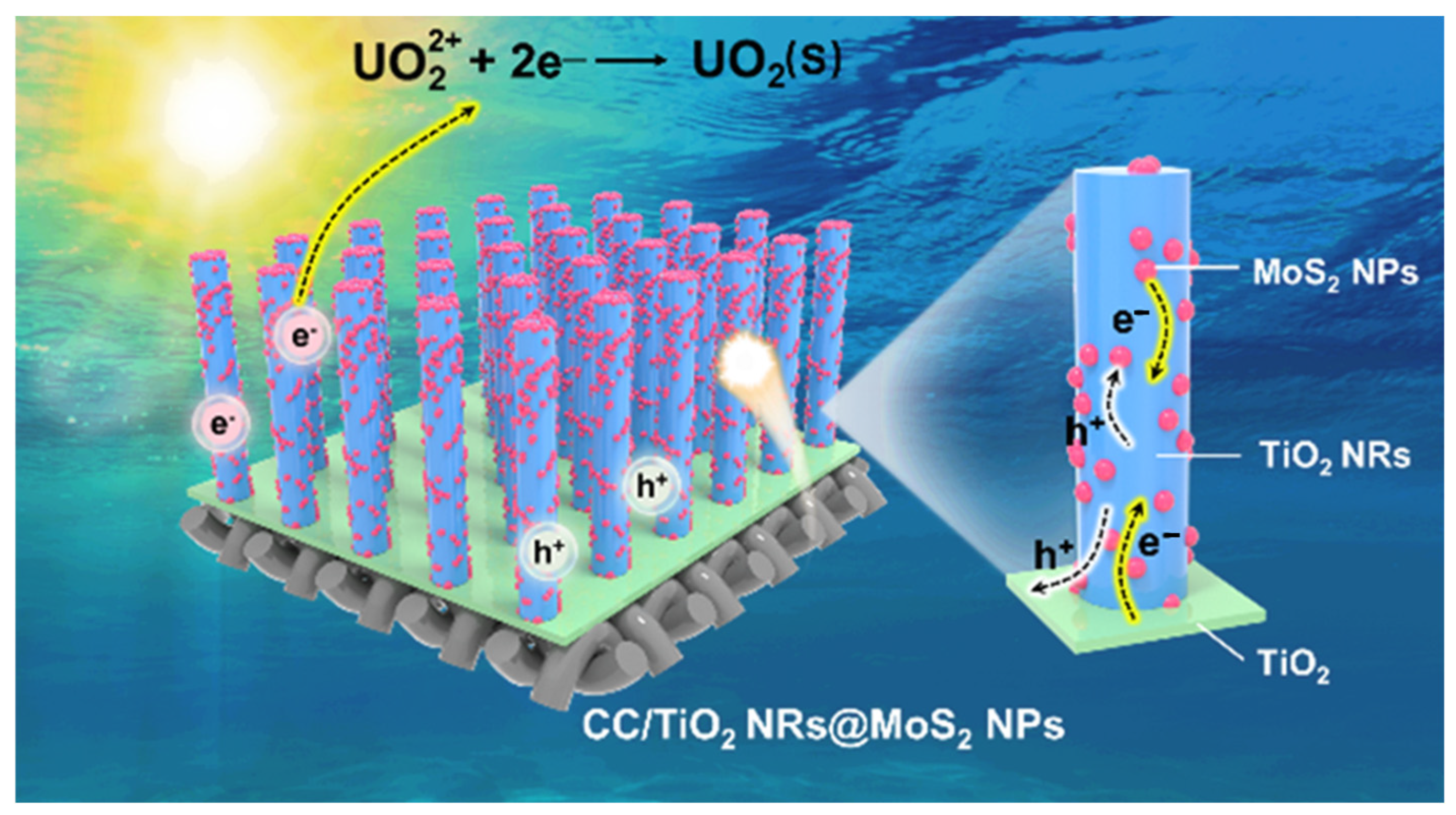
Photocatalysis offers a cost-effective and eco-friendly approach for environmental remediation, yet traditional powdered photocatalysts suffer from poor recyclability and separation challenges. To address these limitations, we developed a recyclable carbon fiber-supported composite photocatalyst (CC/TiO2 NRs@MoS2 NPs) featuring a three-dimensional hierarchical core–shell architecture. This structure comprises a TiO2 seed layer, vertically aligned TiO2 nanorod arrays as the core, and a MoS2 nanoparticle shell, fabricated via sequential deposition. Under simulated solar irradiation, the TiO2@MoS2 heterojunction exhibited significantly enhanced uranium adsorption capacity, achieving a remarkable 97.3% photocatalytic removal efficiency within 2 h. At an initial uranium concentration of 200 ppm, the material demonstrated an exceptional extraction capacity of 976.7 mg g−1, outperforming most reported photocatalysts. These findings highlight the potential of this 3D core–shell design for efficient uranium recovery and environmental purification applications.

Graphical Abstract

1. Introduction

Nuclear energy has emerged as a prominent player in the development and utilization of clean energy resources, owing to its high energy density and minimal carbon emissions, as evidenced by numerous studies [1,2,3,4]. The rapid expansion of nuclear power in China is expected to lead to a significant depletion of on-land uranium reserves. This depletion poses a serious threat to the security and sustainable development of the country’s nuclear energy sector [5]. Photocatalytic technology, as an environmentally benign and sustainable approach characterized by operational safety and cost-effectiveness, can achieve the degradation of pollutants and sewage treatment. And it has enabled the emergence of photocatalytic uranium extraction from seawater—a novel strategy for uranium recovery [6,7,8,9]. Compared with conventional adsorption methods, the photocatalytic reduction of uranium demonstrates superior advantages including enhanced extraction capacity, exceptional selectivity, and minimized environmental impact, exhibiting significant application potential in seawater uranium extraction endeavors [10,11,12].
Titanium dioxide (TiO2) photocatalysts have attracted considerable interest in the realm of photocatalytic water purification. This is primarily attributed to their non-toxicity to humans, stable physicochemical properties, and the ease of large-scale synthesis [13,14]. As an effective semiconductor photocatalyst, TiO2 was first employed in photocatalytic uranium reduction reactions in 1990. However, the practical application of TiO2 is impeded by two critical issues. Firstly, the excessive recombination of electron-hole pairs significantly undermines its photocatalytic efficiency, and its reduction potential is also insufficient. Secondly, the powder-based application format poses a major obstacle to the recyclability of the catalyst [15,16,17]. One-dimensional (1D) nanostructures (nanorods/nanowires) demonstrate exceptional optoelectronic performance through enhanced electron transport kinetics enabled by their high aspect ratio characteristics. The integration of 1D nanomaterials into three-dimensional (3D) array architectures represents an advanced photocatalytic strategy, as such configurations outperform their low-dimensional counterparts in photoelectric conversion efficiency [18,19,20,21]. To overcome the inherent limitations of single-component TiO2 photocatalysts, particularly their weak visible-light absorption capacity and rapid electron-hole recombination, current research efforts are centered on constructing 3D core–shell heterostructures. This is achieved by combining TiO2 nanorod arrays with complementary semiconductors [22]. This architectural design not only enhances the efficiency of solar energy utilization, but also improves the separation of charge carriers. As a result, it serves as a highly effective strategy for boosting the photocatalytic activity of titanium dioxide-based systems [23,24].
In the realm of photocatalytic research, molybdenum disulfide (MoS2), a graphene-like two-dimensional material with unique structural and physicochemical attributes, has emerged as a focal point of investigation [25,26,27]. In recent years, the combination of metal oxide and metal sulfide compounds for photocatalysts has emerged as a burgeoning area of research, drawing significant attention from the scientific community [28]. As an efficient photocatalyst, MoS2 and its derivatives have been widely utilized in photocatalytic heavy metal reduction. Its advantages, including a broad light-absorption range, strong reduction capability, and compatible band structure with TiO2, make it an ideal candidate for constructing TiO2-based heterojunctions [29]. A notable disadvantage that warrants mention is the susceptibility of its sulfur component to oxidation within a relatively short timeframe. Under specific environmental conditions, such as exposure to an oxygen-rich atmosphere or in the presence of strong oxidizing agents, the sulfur atoms in MoS2 can readily undergo oxidation reactions.
Compared to conventional glass substrates, the three-dimensional fibrous architecture of carbon cloth offers distinct advantages. Its enhanced electrical conductivity significantly improves photoelectron transfer kinetics and electron mobility, while the hierarchical porous structure provides substantially greater active site density for improved UO22+ adsorption. Additionally, carbon cloth demonstrates superior chemical stability in corrosive nuclear waste environments compared to glass substrates, along with inherent flexibility that enables scalable reactor designs [30,31].
Therefore, this study developed a carbon cloth-supported three-dimensional core–shell structured TiO2@MoS2 heterojunction material via an impregnation–calcination/solvothermal–recalcination method for photocatalytic U(VI) reduction. The innovation of this study lies in the strategic layer-by-layer construction of core–shell structural units on three-dimensional (3D) porous supports. This approach not only creates expanded spatial domains for charge separation but also enables ordered carrier migration across the entire 3D matrix. By coupling the advantages of heterojunction engineering with array architecture modulation, this strategy provides a novel design paradigm for developing functional materials capable of photocatalytic uranium extraction from seawater.

2. Results and Discussions

Figure 1a shows the dip scorching–solvent hydrothermal–repeated dip scorching approach designed in this study for creating a TiO2 NRs@MoS2 NPs 3D core–shell heterostructure. First, a conformal TiO2 crystal seed layer was uniformly immobilized on the surface of a carbon fiber by dip scorching. Next, a 3D TiO2 nanorod array was created over the surface of the crystal seed layer by the solvent hydrothermal method. Then, MoS2 nanoparticles were attached over the surface of the TiO2 nanorod array as the shell by repeated dip scorching. This multi-step approach ensures precise control over hierarchical architecture and interfacial compatibility for enhanced photocatalytic performance. The series of samples involved in this method are designated as CC, CC/TiO2, CC/TiO2 NRs, and CC/TiO2 NRs@MoS2 NPs, with full component names provided: CC (carbon cloth), TiO2 (titanium dioxide), TiO2 NRs (titanium dioxide nanorods), and MoS2 NPs (molybdenum disulfide nanoparticles).
Scanning electron microscopy (SEM) was used to observe the microstructure and morphological features of CC, CC/TiO2, CC/TiO2 NRs, and CC/TiO2 NRs@MoS2 NPs. The CC substrate consists of woven carbon fibers with a diameter of approximately 25 μm (Figure 1b,f). A three-dimensional photocatalytic unit structure was progressively constructed on the carbon fiber surface to enhance the separation of photogenerated charges. Carbon fibers, widely used in flexible electrode materials due to their excellent conductivity, serve as a recyclable carrier for photocatalytic materials, providing ample space for photogenerated charge diffusion. CC/TiO2 features a TiO2 seed layer coating approximately tens of nanometers thick adhered to the carbon fiber surface (Figure 1c,g), providing a platform for subsequent heterostructure growth. CC/TiO2 NRs were synthesized via solvothermal growth, resulting in highly ordered, vertically aligned TiO2 nanorod arrays densely covering the carbon fiber surface (Figure 1d,h). These nanorods measure approximately 1 μm in length and 150 nm in diameter, significantly increasing the material’s active surface area and providing stable support for subsequent shell coating. The interrod spacing facilitates effective encapsulation of the TiO2 nanorod arrays by the MoS2 shell during subsequent impregnation–calcination.
CC/TiO2 NRs@MoS2 NPs were obtained through secondary impregnation–calcination (Figure 1e,i). SEM images reveal complete coverage of TiO2 nanorods by MoS2, with the original TiO2 arrays becoming barely observable, suggesting the formation of a TiO2@MoS2 core–shell structure. To clarify the interfacial morphology and crystalline structure of the TiO2@MoS2 core–shell heterostructure, high-resolution transmission electron microscopy (HRTEM) was performed. From the HRTEM image in Figure 1j,k, we can see that the TiO2 nanorods have a complete crystal structure and their surfaces are tightly wrapped by numerous ellipsoidal MoS2 nanoparticles, making up a coaxial heterointerface where the core and the shell are in close contact. The absence of an amorphous interfacial layer between highly crystalline TiO2 and MoS2 indicates minimal interfacial charge loss during carrier transport, significantly improving the migration of photogenerated charge carriers. Figure 1l displays two sets of lattice fringes with spacings of 0.630 nm and 0.351 nm, corresponding to the (002) plane of hexagonal MoS2 (PDF#37-1492) and the (101) plane of tetragonal TiO2 (PDF#77-0443), respectively. In conclusion, this study has successfully synthesized a well-defined carbon fiber-supported TiO2@MoS2 core–shell heterostructure material. It is hypothesized that this material will exhibit superior photoelectrochemical performance and thus holds great promise for photocatalytic uranium extraction from seawater.
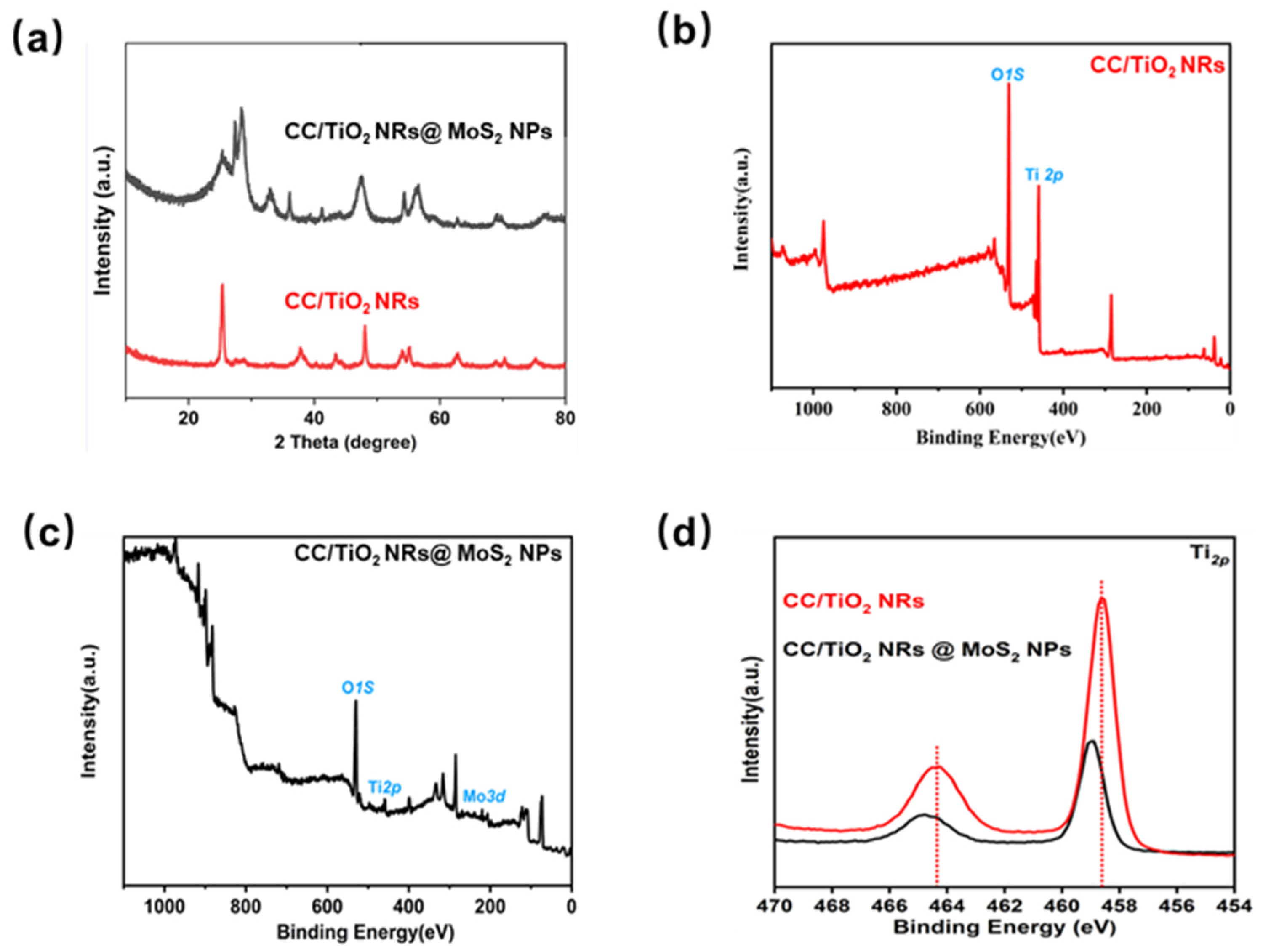
In order to explore how heterojunctions are loaded layer-by-layer at the micro level, CC/TiO2 NRs and CC/TiO2 NRs@MoS2 NPs were synthesized and analyzed by XRD (Figure 2a). In CC/TiO2 NRs, the diffraction peak characteristic of rutile-type TiO2 nanorods exhibits remarkable sharpness and intensity, signifying their high degree of crystallization.
In CC/TiO2 NRs@MoS2 NPs in the CC/TiO2 NRs@MoS2 NP composite, the characteristic diffraction peaks associated with both TiO2 nanorods (NRs) and MoS2 nanoparticles (NPs) are distinctly discernible, offering irrefutable evidence of the successful recombination of TiO2 and MoS2 into a core–shell heterojunction structure. Figure 2b presents the full-spectrum analysis results for CC/TiO2 NRs. The spectrum unequivocally demonstrates that the sample predominantly comprises Ti and O elements. Similarly, Figure 2c illustrates the full-spectrum analysis outcomes for the CC/TiO2 NRs@MoS2 NP composite, where the spectrum clearly reveals the presence of Ti, O, Mo, and S elements as the principal constituents. The prominent peak at approximately 230 eV is attributable to Mo 3d, thereby directly substantiating the successful loading of MoS2 onto the TiO2 nanorods.
The X-ray photoelectron spectroscopy (XPS) spectrum in Figure 2d reveals two distinct peaks at 458.7 eV and 464.2 eV, corresponding to the Ti 2p3/2 and Ti 2p1/2 spin-orbit doublets, respectively, which are characteristic of Ti4+ in the anatase phase of TiO2. These binding energies align well with previously reported values for bulk TiO2, confirming the preservation of the TiO2 nanorod (NR) structure after composite formation. Notably, when compared to the pristine CC/TiO2 NRs, the central positions of both Ti 2p peaks in the CC/TiO2 NRs@MoS2 NP composite exhibit a measurable shift toward higher binding energies. This shift suggests a modification of the local electronic environment around Ti atoms, likely due to strong electronic interactions between the TiO2 host and the MoS2 nanoparticles (NPs). This electronic modulation is critical for enhancing photocatalytic performance, as it may facilitate more efficient separation of photogenerated electron-hole pairs and improve the reduction potential of conduction band electrons for U(VI) reduction.
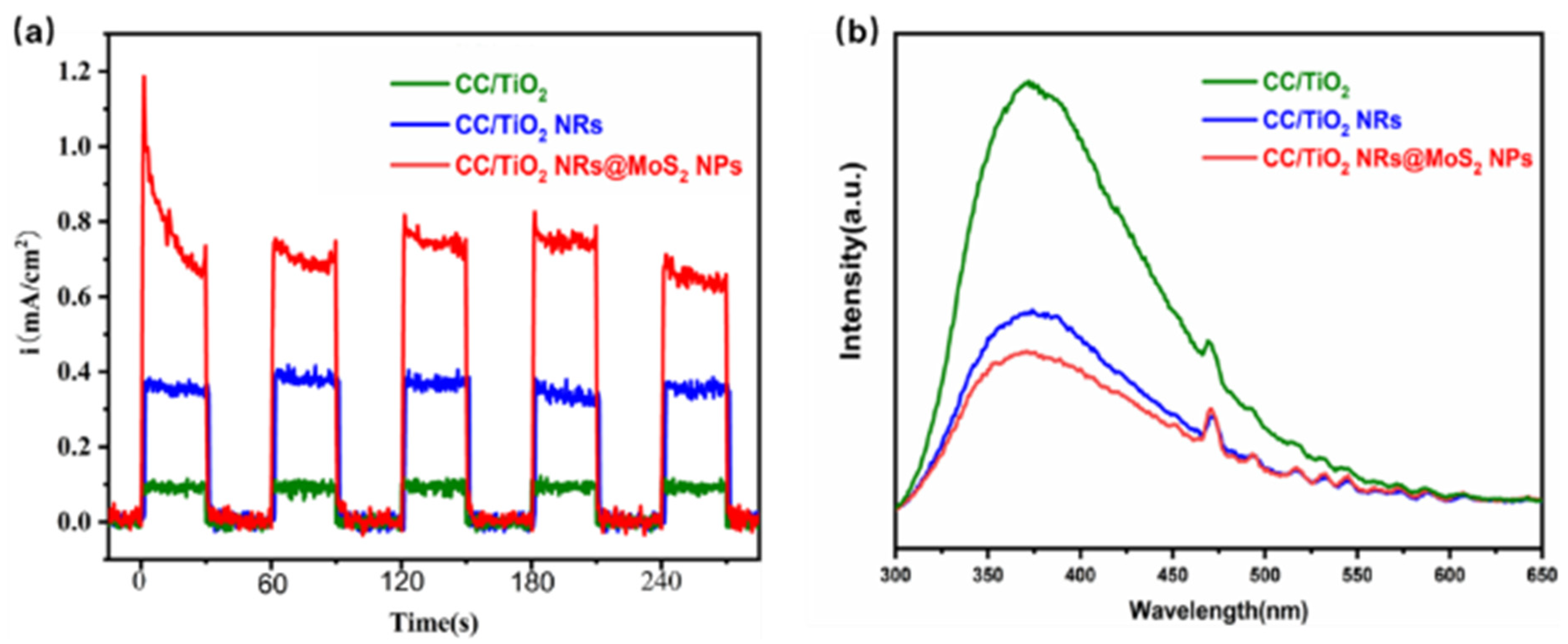
To investigate the enhanced performance of the three-dimensional core–shell heterojunction, transient photocurrent measurements (Figure 3a) were conducted to assess the separation and migration efficiency of photogenerated charge carriers. The heterojunction exhibited periodic “on–off” photocurrent density response curves, and under repeated illumination, the photocatalysts in the electrolyte consistently demonstrated stable and reproducible signals. Figure 3a shows that CC/TiO2, CC/TiO2 NRs, and CC/TiO2 NRs@MoS2 NPs all exhibited stable photocurrent responses under illumination. The transient photocurrent density of CC/TiO2 NRs was about twice that of CC/TiO2 per unit area, and the photocurrent intensity of CC/TiO2 NRs@MoS2 NPs was 1.7 times that of CC/TiO2 NRs. This indicates that the growth of TiO2 nanorods improved the separation of photogenerated charge carriers. Compared to the two-dimensional TiO2 seed layer on carbon cloth, the three-dimensional array structure facilitated rapid electron migration, further suppressing the recombination of photogenerated electrons and holes, thus producing a more stable and a stronger transient photocurrent. With the addition of MoS2, a three-dimensional core–shell heterojunction formed between TiO2 and MoS2. The suitable bandgap and matched energy levels of this heterojunction enhanced the separation of photogenerated charge carriers and improved interfacial charge transfer, leading to the high transient photocurrent intensity.
The behavior of photogenerated charge carriers within the three-dimensional core–shell structure was analyzed using steady-state photoluminescence (PL) spectroscopy (Figure 3b). An excitation wavelength of 350 nm was used to measure the emission spectra of CC/TiO2, CC/TiO2 NRs, and CC/TiO2 NRs@MoS2 NPs in the wavelength range of 300–650 nm. The emission peak intensity of CC/TiO2 NRs@MoS2 NPs was significantly lower than that of CC/TiO2 NRs, indicating a distinct quenching effect. This suggests that the recombination rate of photogenerated electrons and holes in CC/TiO2 NRs@MoS2 NPs was much lower than that in CC/TiO2 NRs. This reduction in recombination is attributed to the three-dimensional core–shell structure formed by MoS2 and TiO2 nanorods, which enabled efficient separation and transfer of charges at their interface.
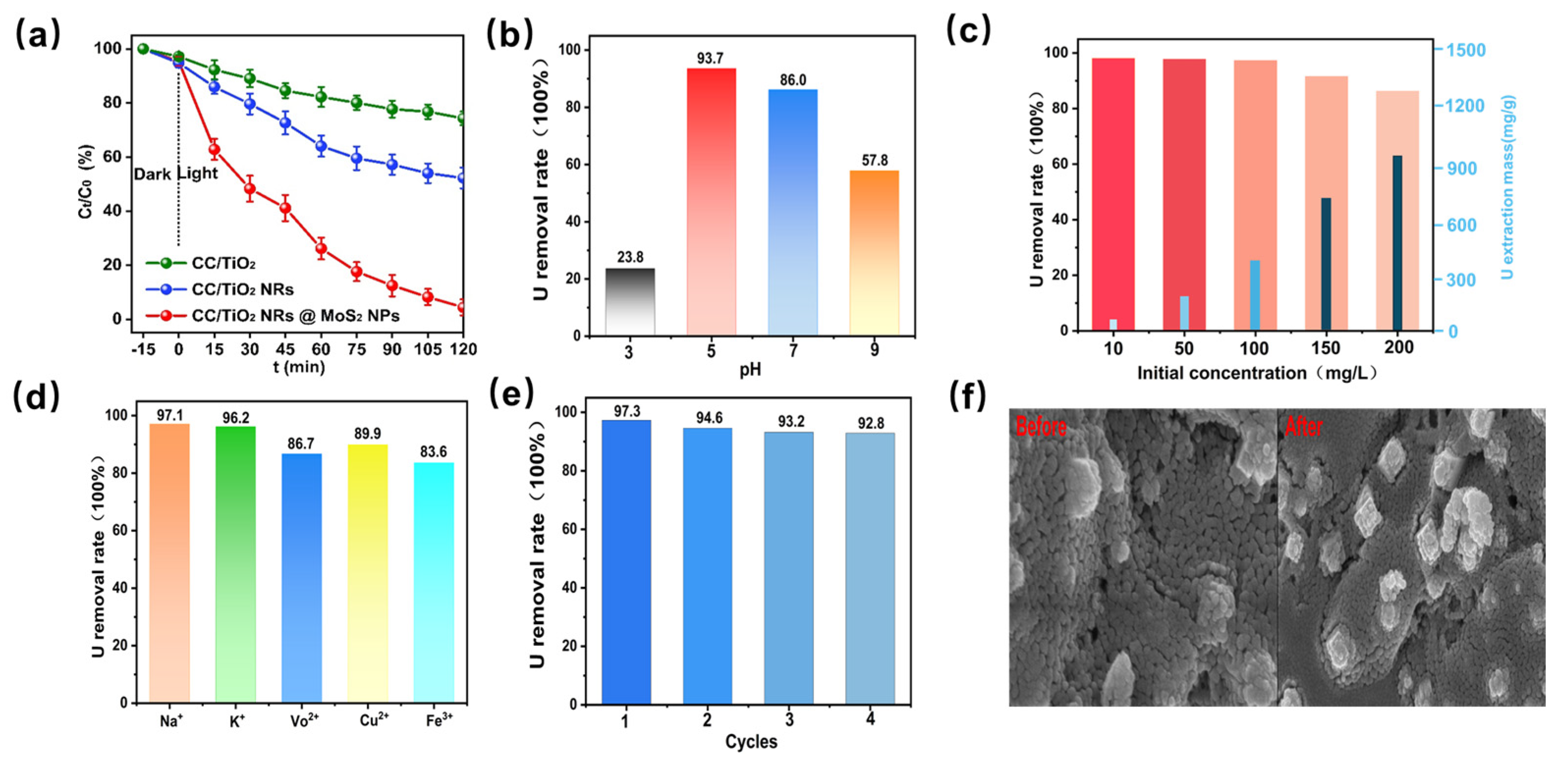
Considering the efficient charge separation and transfer efficiency of CC/TiO2 NRs@MoS2 NPs, their uranium extraction performance was further evaluated. Additional adsorption kinetic experiments were conducted under dark conditions, through which the sufficiency of a 15 min period for the system to reach adsorption equilibrium was confirmed (Figure S1). Under simulated sunlight irradiation, photocatalytic degradation experiments were conducted when the initial uranium concentration was 100 ppm (Figure 4a). After a dark reaction for 15 min, the uranium concentration decreased slightly, which was due to the weak adsorption of uranium on the sample surface. After 2 h of simulated sunlight irradiation, the photocatalytic removal rates of various samples were in the following order: CC/TiO2 NRs@MoS2 NPs (97.3%), CC/TiO2 NRs (53.2%), and CC/TiO2 (27.3%). The degradation performance of the CC/TiO2 NRs@MoS2 NP composite material was significantly higher than that of CC/TiO2 and CC/TiO2 NRs. This excellent performance is attributed to the construction of the three-dimensional core–shell heterostructure, which effectively promotes the separation and migration of photogenerated charge carriers, improves the photoquantum efficiency, constructs continuous and rapid charge separation and transfer channels, enables a large number of photogenerated charges to migrate to the surface of the photocatalyst to participate in the reaction, and thus significantly enhances the photocatalytic activity.
The influence of pH on the uranium extraction reaction was further studied in the pH range of 3–7. As shown in Figure 4b, when the solution was more acidic, the photocatalytic performance of CC/TiO2 NRs@MoS2 NPs for uranium was severely inhibited. As the pH value increased from 3 to 5, the catalytic performance of the catalyst improved significantly. This phenomenon can be attributed to the fact that at lower pH, the increased H+ in the solution and the positively charged surface of the catalyst generate electrostatic repulsion with the positively charged UO22+, hindering the capture of UO22+ by the catalyst and thus affecting the subsequent photoreduction performance.
To explore the saturation extraction capacity of CC/TiO2 NRs@MoS2 NPs for uranium, their photocatalytic uranium extraction ability was tested within the initial concentration range of 10–200 ppm (Figure 4c). After a reaction of 120 min, the removal rate of U(VI) by CC/TiO2 NRs@MoS2 NPs remained at a high level as the initial uranium concentration increased. As the initial uranium concentration increased, the uranium extraction also increased. When the initial uranium concentration was 200 ppm, the uranium extraction capacity of CC/TiO2 NRs@MoS2 NPs reached as high as 976.7 mg g−1. It is worth noting that the uranium extraction level in the experiment did not fully reach the saturation extraction capacity of the photocatalyst. The abundant reaction sites of the three-dimensional core–shell structure ensured the rapid progress of the reaction without a sharp decline in the photoreduction rate due to the occupation of some active sites by the reduced uranium products. More importantly, the coexistence of multiple ions is also a major interference factor in seawater uranium extraction. Common metal ions in seawater, such as Na+, K+, V5+, Cu2+, and Fe3+, were introduced into the U(VI) reaction system to evaluate the anti-interference performance of the photocatalyst (Figure 4d). The influence of Na+ and K+ was slight. When V5+, Cu2+, and Fe3+ were present, the removal rate of uranium by the catalyst decreased slightly. The above results are attributed to the competitive adsorption of V5+, Cu2+, and Fe3+ with UO22+ during the reaction.
The recyclability of the photocatalyst is crucial for practical applications. To verify the stability and recycling effect of CC/TiO2 NRs@MoS2 NPs, four recycling experiments were carried out. After each cycle, the sample was soaked in deionized water for 60 min and dried at 100 °C for reuse. As shown in Figure 4e, even after four repeated uses, the material could still maintain a removal rate of 92.9% for uranium at 200 ppm, demonstrating its excellent reusability. By comparing the SEM images of the samples before and after four cycles (Figure 4f), it was clearly observed that after five cycles the MoS2 nanoparticles were still tightly coated on the TiO2 nanorods, maintaining a stable core–shell heterostructure, which confirmed the reusability of CC/TiO2 NRs@MoS2 NP removal efficiency and desorption rate of U(VI) and facilitated their practical applications (Table S1). By comparing with the literature [32,33,34,35,36,37], the advancement of this material is highlighted.
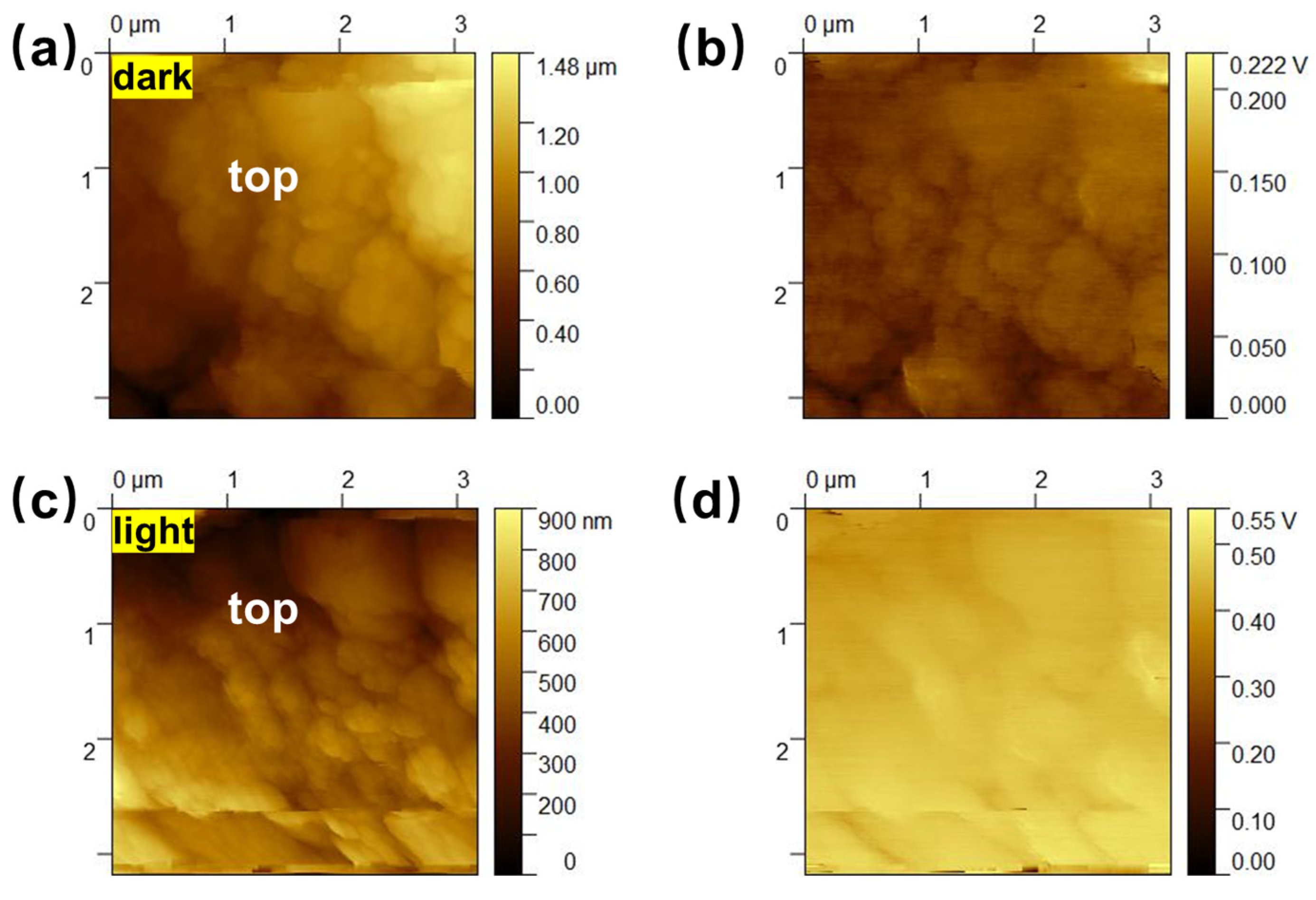
To gain a deeper understanding of how this material efficiently extracts uranium by examining charge transfer within its core–shell structure, we further utilized Kelvin probe force microscopy (KPFM). This technique enabled us to visually capture potential distribution images under illumination, thereby facilitating an in-depth study of charge migration patterns within the CC/TiO2 NRs@MoS2 NPs system. The AFM imaging results demonstrate that, when observed from top to bottom, the three-dimensional core–shell array units in CC/TiO2 NRs@MoS2 NPs are randomly distributed on the surface of the substrate (Figure 5a,c). Under dark conditions, the surface potential of the TiO2 NRs@MoS2 NPs units remains relatively low (Figure 5b). However, upon exposure to illumination, their surface potential increases significantly and exhibits a continuous distribution pattern (Figure 5d). This suggests that the three-dimensional core–shell structure can effectively facilitate the directional migration of charges within three-dimensional space, supporting the process of positive charge migration towards the apex of the TiO2 NRs@MoS2 NP units, away from the CC, under photocatalytic conditions.
Figure 6 summarizes the photocatalytic uranium extraction mechanism of the material in this study. In this study, a TiO2 seed layer, TiO2 nanorods, and MoS2 nanoparticles were constructed layer-by-layer in situ on the surface of carbon fiber materials, ensuring the easy recyclability of the material. The MoS2 nanoparticles coated on the TiO2 nanorods formed a three-dimensional core–shell structure, increasing the catalyst loading and the degree of photocharge separation. Within the unit structure, under the joint regulation of the three-dimensional core–shell array and the heterojunction, positive charges are efficiently transported to the outer surface of the three-dimensional core–shell array units, while negative charges are transferred to the interior of the nanoarray. The photogenerated electrons within the unit are further conducted through carbon fibers, which serve as excellent conductors. Subsequently, uranium is extracted via reduction reactions occurring on the carbon fiber surface, with UO2 identified as the primary reduction product. This method ingeniously achieves efficient charge separation in three-dimensional space, thereby effectively promoting the photocatalytic reduction process for uranium extraction. Notably, this approach significantly reduces carrier recombination efficiency, enhances the generation efficiency of active species, and fully exploits the immense potential of photocatalytic materials for uranium extraction from seawater.

3. Experimental

3.1. Materials and Reagents

Uranyl nitrate (Aladdin Chemical Reagent Co., Ltd., Shanghai, China), thiourea (Aladdin Chemical Reagent Co., Ltd.), ammonium molybdate (Tianjin Tianli Chemical Reagent Co., Ltd., Tianjin, China), titanium tetrabutoxide (>99%, Aladdin Chemical Reagent Co., Ltd.), HNO3 (AR, Xi’an Sanpu Chemical Reagent Co., Ltd., Xi’an, China), sodium nitrate (Chengdu Jinshan Chemical Reagent Co., Ltd., Chengdu, China), potassium chloride (Chengdu Jinshan Chemical Reagent Co., Ltd.), sodium chloride (Chengdu Jinshan Chemical Reagent Co., Ltd.), calcium chloride (Chengdu Jinshan Chemical Reagent Co., Ltd.), magnesium chloride (Chengdu Jinshan Chemical Reagent Co., Ltd.), NaOH (AR, Xi’an Sanpu Chemical Reagent Co., Ltd.), absolute ethanol (AR, Tianjin Hengxing Chemical Reagent Co., Ltd., Tianjin, China), potassium hydroxide (>99.99%, Aladdin Chemical Reagent Co., Ltd.), and deionized water (laboratory-prepared). All reagents were of analytical grade and used without further purification.

3.2. Preparation of Photocatalysts

3.2.1. Preparation of CC/TiO2 Seeds (Carbon Fiber-Supported TiO2 Seed Layer)

Commercial carbon fiber cloth (CC) was used as the substrate. Prior to functionalization, the cloth was thoroughly rinsed with deionized water to eliminate surface contaminants and subsequently dried at 60 °C in an oven. A 1% (v/v) titanium tetrabutoxide (TTIP)-isopropanol solution was uniformly deposited onto the carbon fiber surface via dropwise addition using a micropipette until complete wetting was observed. The sample was then dried at 60 °C for 10 min, and this coating procedure was repeated three times to ensure uniform coverage. Following the coating steps, the sample underwent calcination in a muffle furnace at 400 °C for 4 h under ambient atmosphere, resulting in the formation of a carbon fiber-supported TiO2 seed layer, denoted as CC/TiO2 seeds.

3.2.2. Preparation of CC/TiO2 NRs (Carbon Fiber-Supported TiO2 Nanorod Arrays)

The hydrothermal synthesis was conducted by sequentially introducing 50 mL of 6 mol L−1 hydrochloric acid (HCl) and 500 μL of titanium tetrabutoxide (TTIP) into a 200 mL Teflon-lined stainless-steel autoclave. The mixture was vigorously stirred for 30 min to ensure homogeneity. Subsequently, the pre-prepared CC/TiO2 seeds were immersed in the reaction solution, and hydrothermal treatment was performed at 150 °C for 10 h in an oven. After natural cooling to room temperature, the resulting product was thoroughly rinsed three times with absolute ethanol followed by ultrapure water to remove residual reactants and byproducts. Finally, the sample was vacuum-dried at 100 °C for 8 h to yield carbon fiber-supported TiO2 nanorods (CC/TiO2 NRs).

3.2.3. Preparation of CC/TiO2NRs@MoS2 NPs (Carbon Fiber-Supported 3D Core–Shell Structure)

A precursor solution was formulated by dissolving 1 mmol of ammonium molybdate tetrahydrate ((NH4)6Mo7O24·4H2O) and 30 mmol of thiourea (CH4N2S) in 30 mL of deionized water under continuous magnetic stirring at room temperature for 2 h to ensure complete dissolution and homogeneity. The as-prepared CC/TiO2 nanorods (NRs) were then immersed in the precursor solution for 30 min to facilitate adsorption of the molybdenum and sulfur precursors. Subsequently, the sample was calcined in a muffle furnace at 400 °C for 4 h under ambient atmosphere to induce thermal decomposition and formation of MoS2 nanoparticles (NPs) on the TiO2 nanorod surface, yielding the CC/TiO2 NRs@MoS2 NP composite.
For all three materials studied (CC, CC/TiO2 NRs, and CC/TiO2 NRs@MoS2 NPs), the mass loadings were consistently controlled at approximately 350 ± 5 mg across multiple batches, as determined by gravimetric analysis.

3.3. Characterization

The phase composition and crystallinity of the samples were analyzed using X-ray diffraction (XRD) performed on a Bruker D8 Advanced instrument (Karlsruhe, Germany) with Cu Kα radiation (λ = 0.15401 nm) at 40 kV. Scans were conducted from 5° to 90° at a rate of 5° min−1. Surface elemental composition and chemical states were investigated via X-ray photoelectron spectroscopy (XPS) using an AXIS ULTRA DLD system (Cheshire, UK). Morphological features and elemental distribution were examined using a field-emission scanning electron microscope (FESEM, Gemini, Friedrichshafen, Germany) coupled with energy-dispersive X-ray spectroscopy (EDS) at an accelerating voltage of 15 kV. High-resolution transmission electron microscopy (HRTEM, JEM-2100F, JEOL Ltd., Tokyo, Japan) was employed to analyze microstructural details and lattice fringes. Optical absorption properties were assessed using ultraviolet–visible diffuse reflectance spectroscopy (UV–Vis DRS, Ocean Optics SB650, Orlando, FL, USA). Photoluminescence (PL) spectra and time-resolved fluorescence measurements were acquired with a fluorescence spectrometer (F-7000, Hitachi, Tokyo, Japan). Photoelectrochemical performance was evaluated via chronoamperometry using an electrochemical workstation (Princeton P4000, Trenton, NJ, USA).

3.4. Uranium Extraction Performance Evaluation

3.4.1. Preparation of Uranium-Containing Simulated Seawater

A base of simulated seawater was prepared by dissolving 23 g sodium chloride, 11 g magnesium chloride, 4 g sodium sulfate, 2 g calcium chloride, and 0.7 g potassium chloride in 300 mL deionized water within a 500 mL beaker. The solution was transferred to a 1000 mL volumetric flask and diluted to the mark with deionized water. To prepare a 1000 mg L−1 uranium stock solution, 2.11 g uranyl nitrate was dissolved in 100 mL simulated seawater and diluted to 1000 mL. Serial dilutions of this stock solution (100, 200, 300, 400, 500, and 600 mL aliquots) were prepared in 1000 mL volumetric flasks by dilution with simulated seawater, yielding uranium concentrations of 100–600 mg L−1. By adjusting to pH = 8 with a 0.2 M sodium bicarbonate solution and 0.1 M diluted hydrochloric acid, we obtained simulated seawater containing the standard uranium concentration, as required. This prepared simulated seawater was then applied to the experimental testing of the materials’ uranium extraction performance in the simulated marine conditions.

3.4.2. Uranium Concentration Detection Method

Standard solutions (100–600 mg L−1 uranium) were analyzed by mixing 1 mL of each solution with arsenazo III reagent (1.0 × 10⁻⁴ M, prepared by diluting 5.0 mL of 2.0 × 10⁻³ M arsenazo III stock solution in 0.1 M perchloric acid to 100 mL with the same acid medium) and deionized water. Absorbance at 651 nm was measured using a UV–Vis spectrophotometer (SB650, USA) to establish a linear calibration curve relating uranium concentration to absorbance. Unknown concentrations were determined via this regression model.

3.4.3. Photocatalytic Uranium Extraction Experiment

A 100 mL uranium-containing seawater solution (1 mg L−1 U) was irradiated in a glass reactor under a xenon lamp adjusted to simulate subsurface solar irradiance (20 mW cm−2 at the reactor surface). We ensured that the carbon cloth-loaded catalyst (10 cm2) was immersed in the reaction solution and in full contact with it, using a nylon mesh to avoid mechanical contact with the magnetic stirrer (400 rpm). Samples (3 mL) were collected hourly from the mid-depth of the solution over 4 h using a hydrophilic syringe filter (Xi’an Sanpu Chemical Reagent Co., Ltd., China) (0.22 μm).

4. Conclusions

This study successfully developed a high-performance, recyclable photocatalytic system for uranium extraction by immobilizing TiO2@MoS2 core–shell heterojunction nanorods on carbon fiber (CC/TiO2 NRs@MoS2 NPs). Comprehensive physicochemical characterizations confirmed the successful fabrication of the 3D hierarchical core–shell architecture, which significantly enhanced catalyst loading density and interfacial charge separation efficiency. Photocatalytic experiments demonstrated exceptional uranium removal performance (97.3% efficiency within 2 h) and an unprecedented extraction capacity (976.7 mg g−1 at 200 ppm U(VI)), outperforming most reported photocatalysts. Mechanistic investigations via surface potential mapping revealed that the stable core–shell structure facilitated sequential processes of photoexcitation, charge separation, internal transport, surface accumulation, and interfacial reduction, thereby achieving efficient spatial charge management. These findings provide critical insights into the design of advanced photocatalytic architectures for environmental remediation and resource recovery.

Supplementary Materials

The following supporting information can be downloaded at: https://www.mdpi.com/article/10.3390/catal15080769/s1, Table S1: Comparative analysis of uranium extraction performance, capacity, selectivity, and reusability. Figure S1: Adsorption kinetic experiments under dark conditions.

Author Contributions

Conceptualization, T.Z. and C.X.; methodology, F.Z.; data curation, B.Z.; writing—original draft preparation, T.Z. and C.X. funding acquisition, F.Z. All authors have read and agreed to the published version of the manuscript.

Funding

This research received no external funding.

Data Availability Statement

Data is contained within the article.

Conflicts of Interest

The authors declare no conflicts of interest.

References

  1. Gralla, F.; Abson, D.J.; Møller, A.P.; Lang, D.J.; Von Wehrden, H. Energy Transitions and National Development Indicators: A Global Review of Nuclear Energy Production. Renew. Sustain. Energy Rev. 2017, 70, 1251–1265. [Google Scholar] [CrossRef]
  2. Harper, G.; Sommerville, R.; Kendrick, E.; Driscoll, L.; Slater, P.; Stolkin, R.; Walton, A.; Christensen, P.; Heidrich, O.; Lambert, S.; et al. Recycling Lithium-Ion Batteries from Electric Vehicles. Nature 2019, 575, 75–86. [Google Scholar] [CrossRef] [PubMed]
  3. Niu, B.; Xu, Z.; Xiao, J.; Qin, Y. Recycling Hazardous and Valuable Electrolyte in Spent Lithium-Ion Batteries: Urgency, Progress, Challenge, and Viable Approach. Chem. Rev. 2023, 123, 8718–8735. [Google Scholar] [CrossRef]
  4. Yang, T.; Luo, D.; Zhang, X.; Gao, S.; Gao, R.; Ma, Q.; Park, H.W.; Or, T.; Zhang, Y.; Chen, Z. Sustainable Regeneration of Spent Cathodes for Lithium-Ion and Post-Lithium-Ion Batteries. Nat. Sustain. 2024, 7, 776–785. [Google Scholar] [CrossRef]
  5. Parsons, J.; Buongiorno, J.; Corradini, M.; Petti, D. A Fresh Look at Nuclear Energy. Science 2019, 363, 105. [Google Scholar] [CrossRef]
  6. Chen, T.; Yu, K.; Dong, C.; Yuan, X.; Gong, X.; Lian, J.; Cao, X.; Li, M.; Zhou, L.; Hu, B.; et al. Advanced Photocatalysts for Uranium Extraction: Elaborate Design and Future Perspectives. Coord. Chem. Rev. 2022, 467, 214615. [Google Scholar] [CrossRef]
  7. Hu, Y.; Tang, D.; Shen, Z.; Yao, L.; Zhao, G.; Wang, X. Photochemically Triggered Self-Extraction of Uranium from Aqueous Solution under Ambient Conditions. Appl. Catal. B Environ. 2023, 322, 122092. [Google Scholar] [CrossRef]
  8. Li, P.; Wang, J.; Wang, Y.; Liang, J.; Pan, D.; Qiang, S.; Fan, Q. An Overview and Recent Progress in the Heterogeneous Photocatalytic Reduction of U(VI). J. Photochem. Photobiol. C Photochem. Rev. 2019, 41, 100320. [Google Scholar] [CrossRef]
  9. Zheng, A.L.T.; Sinin, A.E.; Jin, W.T.; Feng, K.L.; Boonyuen, S.; Chung, E.L.T.; Lease, J.; Andou, Y. Rare Earth Elements for Enhancing Photocatalysis in Pollutant Degradation and Water Treatment. Int. J. Environ. Sci. Technol. 2025, 22, 7247–7270. [Google Scholar] [CrossRef]
  10. Kumar, V.; Singh, V.; Kim, K.-H.; Kwon, E.E.; Younis, S.A. Metal-Organic Frameworks for Photocatalytic Detoxification of Chromium and Uranium in Water. Coord. Chem. Rev. 2021, 447, 214148. [Google Scholar] [CrossRef]
  11. Xie, Y.; Liu, Z.; Geng, Y.; Li, H.; Wang, N.; Song, Y.; Wang, X.; Chen, J.; Wang, J.; Ma, S.; et al. Uranium Extraction from Seawater: Material Design, Emerging Technologies and Marine Engineering. Chem. Soc. Rev. 2023, 52, 97–162. [Google Scholar] [CrossRef]
  12. Xie, Y.; Chen, C.; Ren, X.; Wang, X.; Wang, H.; Wang, X. Emerging Natural and Tailored Materials for Uranium-Contaminated Water Treatment and Environmental Remediation. Prog. Mater. Sci. 2019, 103, 180–234. [Google Scholar] [CrossRef]
  13. Huang, T.; Lu, J.; Xiao, R.; Wu, Q.; Yang, W. Enhanced Photocatalytic Properties of Hierarchical Three-Dimensional TiO2 Grown on Femtosecond Laser Structured Titanium Substrate. Appl. Surf. Sci. 2017, 403, 584–589. [Google Scholar] [CrossRef]
  14. Hwang, Y.J.; Hahn, C.; Liu, B.; Yang, P. Photoelectrochemical Properties of TiO2 Nanowire Arrays: A Study of the Dependence on Length and Atomic Layer Deposition Coating. ACS Nano 2012, 6, 5060–5069. [Google Scholar] [CrossRef] [PubMed]
  15. Wang, Y.; Yang, W.; Chen, X.; Wang, J.; Zhu, Y. Photocatalytic Activity Enhancement of Core-Shell Structure g-C3N4@TiO2 via Controlled Ultrathin g-C3N4 Layer. Appl. Catal. B Environ. 2018, 220, 337–347. [Google Scholar] [CrossRef]
  16. Wang, Z.; Tong, Y.; Dang, L.; Gao, F.; Lu, Q. Templated Synthesis of Titanium Dioxide Tube-in-Tube Superstructures with Enhanced Photocatalytic and Lithium Storage Performance. Chem. Eng. J. 2019, 370, 1434–1439. [Google Scholar] [CrossRef]
  17. Wei, N.; Liu, Y.; Feng, M.; Li, Z.; Chen, S.; Zheng, Y.; Wang, D. Controllable TiO2 Core-Shell Phase Heterojunction for Efficient Photoelectrochemical Water Splitting under Solar Light. Appl. Catal. B Environ. 2019, 244, 519–528. [Google Scholar] [CrossRef]
  18. Chen, X.; Cheng, Y.; Zhang, B.; Zhou, J.; He, S. Gradient-Concentration RuCo Electrocatalyst for Efficient and Stable Electroreduction of Nitrate into Ammonia. Nat. Commun. 2024, 15, 6278. [Google Scholar] [CrossRef]
  19. Kim, K.-H.; Lee, H.; Huang, X.; Choi, J.H.; Chen, C.; Kang, J.K.; O’Hare, D. Energy-Efficient Electrochemical Ammonia Production from Dilute Nitrate Solution. Energy Environ. Sci. 2023, 16, 663–672. [Google Scholar] [CrossRef]
  20. Wang, Z.; Liu, S.; Wang, M.; Zhang, L.; Jiang, Y.; Qian, T.; Xiong, J.; Yang, C.; Yan, C. In Situ Construction of Metal–Organic Frameworks as Smart Channels for the Effective Electrocatalytic Reduction of Nitrate at Ultralow Concentrations to Ammonia. ACS Catal. 2023, 13, 9125–9135. [Google Scholar] [CrossRef]
  21. Zhang, L.; Jia, Y.; Zhan, J.; Liu, G.; Liu, G.; Li, F.; Yu, F. Dopant-Induced Electronic States Regulation Boosting Electroreduction of Dilute Nitrate to Ammonium. Angew. Chem. Int. Ed. 2023, 62, e202303483. [Google Scholar] [CrossRef]
  22. Wang, M.; Ioccozia, J.; Sun, L.; Lin, C.; Lin, Z. Inorganic-Modified Semiconductor TiO2 Nanotube Arrays for Photocatalysis. Energy Environ. Sci. 2014, 7, 2182–2202. [Google Scholar] [CrossRef]
  23. Chand, H.; Liu, Z.; Wei, Q.; Gaballah, M.S.; Li, W.; Osmolovskaya, O.; Podurets, A.; Voznesenskiy, M.; Pismenskaya, N.; Padhye, L.P.; et al. Performance and Mechanism of Chromium Removal Using Flow Electrode Capacitive Deionization (FCDI): Validation and Optimization. Sep. Purif. Technol. 2024, 340, 126696. [Google Scholar] [CrossRef]
  24. Guo, H.; Wei, Q.; Wu, Y.; Qiu, W.; Li, H.; Zhang, C. Enhanced Nitrate Removal from Groundwater Using a Conductive Spacer in Flow-Electrode Capacitive Deionization. Chin. Chem. Lett. 2024, 35, 109325. [Google Scholar] [CrossRef]
  25. Chen, L.; Yang, S.; Mu, L.; Ma, P.-C. Three-Dimensional Titanium Dioxide/Graphene Hybrids with Improved Performance for Photocatalysis and Energy Storage. J. Colloid Interface Sci. 2018, 512, 647–656. [Google Scholar] [CrossRef]
  26. Feng, J.; Graf, M.; Liu, K.; Ovchinnikov, D.; Dumcenco, D.; Heiranian, M.; Nandigana, V.; Aluru, N.R.; Kis, A.; Radenovic, A. Single-Layer MoS2 Nanopores as Nanopower Generators. Nature 2016, 536, 197–200. [Google Scholar] [CrossRef]
  27. Pham, V.P.; Yeom, G.Y. Recent Advances in Doping of Molybdenum Disulfide: Industrial Applications and Future Prospects. Adv. Mater. 2016, 28, 9024–9059. [Google Scholar] [CrossRef] [PubMed]
  28. Tahir, M.B.; Rafique, M.; Rafique, M.S.; Fatima, N.; Israr, Z. Metal oxide-and metal sulfide-based nanomaterials as photocatalysts. In Nanotechnology and Photocatalysis for Environmental Applications; Elsevier: Amsterdam, The Netherlands, 2020; pp. 77–96. [Google Scholar]
  29. Mamiyev, Z.; Balayeva, N.O. PbS nanostructures: A review of recent advances. Mater. Today Sustain. 2023, 21, 100305. [Google Scholar] [CrossRef]
  30. Pan, M.; Cui, C.; Tang, W.; Guo, Z.; Zhang, D.; Xu, X.; Li, J. Carbon Cloth as an Important Electrode Support for the High Selective Electrosorption of Uranium from Acidic Uranium Mine Wastewater. Sep. Purif. Technol. 2022, 281, 119843. [Google Scholar] [CrossRef]
  31. Zhang, B.; Shan, X.; Yu, J.; Zhang, H.; Tawfik Alali, K.; Liu, Q.; Zhu, J.; Yu, J.; Liu, J.; Li, R.; et al. Facile Synthesis of TiO2-PAN Photocatalytic Membrane with Excellent Photocatalytic Performance for Uranium Extraction from Seawater. Sep. Purif. Technol. 2024, 328, 125026. [Google Scholar] [CrossRef]
  32. Xu, Y.; Zhang, H.; Liu, Q.; Liu, J.; Chen, R.; Yu, J.; Zhu, J.; Li, R.; Wang, J. Surface Hybridization of π-Conjugate Structure Cyclized Polyacrylonitrile and Radial Microsphere Shaped TiO2 for Reducing U(VI) to U(IV). J. Hazard. Mater. 2021, 416, 125812. [Google Scholar] [CrossRef] [PubMed]
  33. Li, M.; Wang, R.; Liu, T.; Chen, Q.; Li, N.; Zhou, L.; Yu, K.; Liu, H.; Gong, X.; He, R.; et al. Integrating Surface Functional Modification and Energy-Level Adapted Coupling of Photocatalyst with Ultrafast Carrier Separation for Uranium Extraction. Sep. Purif. Technol. 2023, 309, 123121. [Google Scholar] [CrossRef]
  34. Wang, C.; Jiao, H.; Wu, Y.; Na, P. Amidoxime-Functionalized TiO2 Nanotube Arrays Plate Photocatalyst for Efficient Extracting and Recovering Uranium from Salt Lakes: Bench-Scale Experiments and Theoretical Calculation. Sep. Purif. Technol. 2024, 339, 126556. [Google Scholar] [CrossRef]
  35. Ma, X.; Meihaus, K.R.; Yang, Y.; Zheng, Y.; Cui, F.; Li, J.; Zhao, Y.; Jiang, B.; Yuan, Y.; Long, J.R.; et al. Photocatalytic Extraction of Uranium from Seawater Using Covalent Organic Framework Nanowires. J. Am. Chem. Soc. 2024, 146, 23566–23573. [Google Scholar] [CrossRef]
  36. Pan, J.; Xiao, B.; Zhu, W.; Yang, Y.; Huang, H.; Lian, Z.; Zhang, T.; Qiu, F.; Xue, S.; Pang, H. Photocatalytic Uranium Extraction Boosted by Dual Effective Active Sites of Porphyrin Metal-Organic Frameworks. Nano Res. 2024, 17, 6713–6720. [Google Scholar] [CrossRef]
  37. Xu, M.; Yu, F.; Liu, Y.; Li, W.; Li, C.; Song, F.; Wu, G.; Xu, Z.; Qiu, J. Integrating Uranyl-Affinity “Hooks” into Conjugated Polymers Achieving Giant Built-in Electric Field for Boosting Photocatalytic Uranium Extraction from Seawater. Macromolecules 2024, 57, 5679–5690. [Google Scholar] [CrossRef]
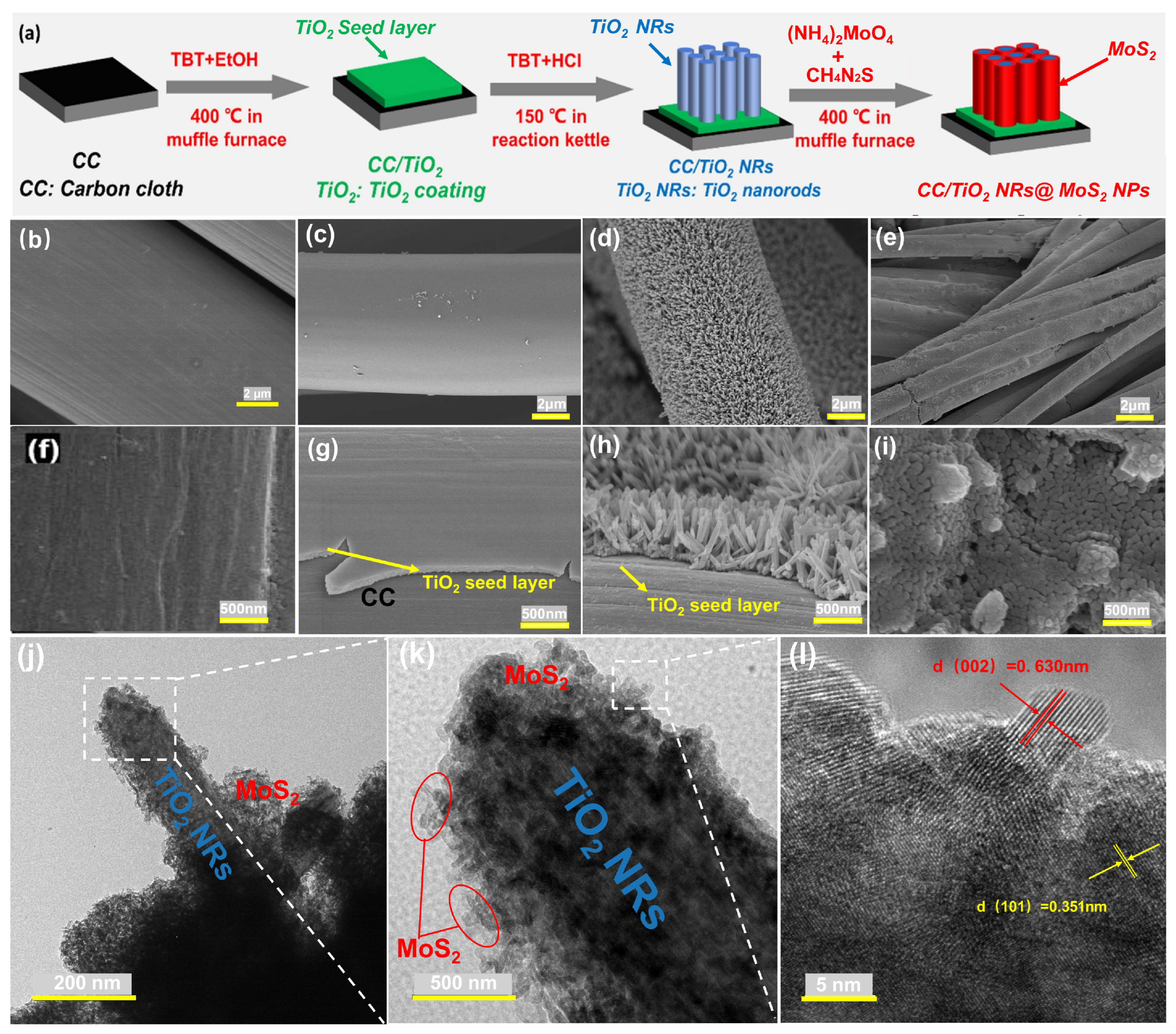
Figure 1. (a) Synthesis of CC/TiO2 NRs@MoS2 NPs via stepwise chemical reactions. SEM images of fabricated (b,f) CC, (c,g) CC/TiO2, (d,h) CC/TiO2 NRs, and (e,i) CC/TiO2 NRs@MoS2 NPs; TEM/HRTEM images of (jl) CC/TiO2 NRs@MoS2 NPs.
Catalysts 15 00769 g001
Figure 2. (a) XRD patterns of the prepared samples of of CC/TiO2 NRs@MoS2 NPs and CC/TiO2 NRs. (b) XPS survey spectrogram of CC/TiO2 NRs. (c) XPS survey spectrogram of CC/TiO2 NRs@MoS2 NPs. (d) High resolution Ti2p spectrogram of CC/TiO2 NRs and CC/TiO2 NRs@MoS2 NPs.
Catalysts 15 00769 g002
Figure 3. (a) Transient photocurrent response diagram of CC/TiO2, CC/TiO2 NRs, and CC/TiO2 NRs@MoS2 NPs (I–t curve). (b) Steady-state PL spectrum of CC/TiO2, CC/TiO2 NRs, and CC/TiO2 NRs@MoS2 NPs.
Catalysts 15 00769 g003
Figure 4. (a) Photocatalytic uranium reduction performance curves of CC/TiO2 NRs@MoS2 NPs, CC/TiO2 NRs, and CC under simulated solar irradiation. (b) Effect of solution pH on the photocatalytic uranium extraction efficiency of CC/TiO2 NRs@MoS2 NPs. (c) Photocatalytic extraction capacity of CC/TiO2 NRs@MoS2 NPs for uranium in the initial uranium concentration range of 1–200 ppm. (d) The removal efficiency and desorption rate of U(VI) by CC/TiO2 NRs@MoS2 NPs through five consecutive cycles. (e) The removal and elution rate of U(VI) during the four successive repeated reactions. (f) Comparative SEM of CC/TiO2 NRs@MoS2 NPs before and after photocatalytic uranium reduction.
Catalysts 15 00769 g004
Figure 5. (a) AFM of image by KPFM of CC/TiO2 NRs@MoS2 NPs under dark conditions. (b) Surface potential image represented by KPFM of CC/TiO2 NRs@MoS2 NPs under dark conditions. (c) AFM of image by KPFM of CC/TiO2 NRs@MoS2 NPs under illuminated conditions. (d) Surface potential image represented by KPFM of CC/TiO2 NRs@MoS2 NPs under illuminated conditions.
Catalysts 15 00769 g005
Figure 6. Possible mechanism diagram for photocatalytic uranium extraction from seawater.
Catalysts 15 00769 g006
Disclaimer/Publisher’s Note: The statements, opinions and data contained in all publications are solely those of the individual author(s) and contributor(s) and not of MDPI and/or the editor(s). MDPI and/or the editor(s) disclaim responsibility for any injury to people or property resulting from any ideas, methods, instructions or products referred to in the content.