Abstract
Selective hydrogenations of lignin-derived phenolic compounds represent essential processes in the chemical industry, especially for production of a multitude of fine chemicals. However, selective hydrogenation of phenolic compounds in water phase suffers from low conversion. Here we report a catalyst of well-dispersed Ru clusters fixed in N-doped mesoporous hollow carbon spheres (Ru@N-CS) for enhanced cyclohexanol productivity in phenol hydrogenation at mild aqueous condition. This superhydrophobicity carbon spheres appear to selectively allow diffusion of phenol and hydrogen molecules to the electron-rich coordination unsaturated Ru active sites, while confining the reactants there to enhance its reaction probability. The Ru@N-CS catalyst can selectively hydrogenate phenol at 80 °C and 0.5 MPa of H2 in 30 min in aqueous medium with phenol conversions of 100% and ~100% cyclohexanol selectivity, corresponding to cyclohexanol productivity up to 471 per g of Ru per minute. The TOF value is up to 9980 h−1, which 14 times more than Ru nanoparticles supported on N-doped carbon hollow spheres (Ru/N-CS). This work provides an important catalytic system for upgrading of bio-oil into value-added chemicals under mild aqueous-phase.
1. Introduction
Finite fossil fuel reserves and the increasing CO2 level in the Earth’s atmosphere are reasons to identify and develop sustainable sources of energy, fuels, and chemicals. In this respect, substantial research efforts have been directed towards the processing of lignocellulosic biomass [1]. The bio-oil, is obtained easily via fast pyrolysis of lignocellulosic biomass [2], which could be upgraded into high-value chemicals by the selective catalytic hydrogenation [3,4]. In the bio-oil, lignin-derived phenolic compounds account for 25–30%, among them, phenol is one of the important components. In addition, there is 10–13 wt% of water in the bio-oil. Therefore, catalytic hydrogenation of phenols directly in aqueous solvent is of more practical importance in the upgrading of bio-oil. Phenol is selected as a model compound to study the quality improvement of bio-oil.
Phenol could be hydrogenated for the preparation of high added-value cyclohexanol, which is a key synthetic intermediate for synthesis of adipic acid for nylon 66 [5], as well as a key raw material for the preparation of surfactants, plasticizers, and detergents [6,7]. Phenol obtained by the pyrolysis of biomass undergoes efficient catalytic hydrogenation to produce cyclohexanol, which not only improves the utilization of biomass, but also, for bio-oil, improves its calorific value and reduces toxicity [8].
Recently, several research has been reported successful aqueous-phase hydrogenation of phenol using Ru nanoparticles, which have great advantages for their outstanding hydrogenation due to its capability for effective activation of hydrogen under mild conditions [9,10]. However, the number of reuses of catalysts is generally 3–5 times (Table S2). These catalysts are mainly supported by metal oxides. This phenomenon was explained by a serious leaching into the solvent or agglomeration into larger particles of Ru metal active center during the reaction in aqueous solvent, leading to catalyst inactivation. Furthermore, these catalysts showed relatively low activity. That is, it takes a long time to obtain cyclohexanol as the only product by hydrogenation of phenol in the liquid phase (Table S2). Zhan et al. synthesized a composite catalyst (Ru/Nb2O5−nC18PA) coated with octadecylphosphonic acid (C18PA), which was applied for the hydrogenation of phenol to produce cyclohexanol. The results showed that under a hydrogen pressure of 12 bar and 80 °C, nearly 100% conversion of phenol and 93% yield of cyclohexanol were achieved within 4 h [11]. Karakhanov et al. prepared a dendrimer-stabilized Ru nanoparticles immobilized in organo-silica catalyst for hydrogenation of phenol. The results showed that conversion of phenol was 100%, and selectivity of cyclohexanol was 100% at 85 °C and 3 MPa of hydrogen after 6 h [12].
Carbon-based material owns the permeability, good thermal and mechanical stability, adjustable high specific surface area, and controlled porosity properties, which make them ideal candidates for applications in support for catalyst [13]. Moreover, nitrogen incorporation can create active sites and further enhance the catalytic activity, because the resultant nitrogen-doped carbon features better chemical reactivity [14]. Furthermore, the surface of carbon material was modified with hydrophobicity to increase its structural stability in aqueous solvent. Therefore, preventing Ru fallen off or agglomeration, and keeping a high structural stability, should maintain high conversion of phenol and selectivity of cyclohexanol after many cycles. However, this strategy is challenging.
In this study, we addressed this challenge by finely controlling Ru clusters fixed in mesoporous N-doped hollow carbon spheres (Ru@N-CS), that rendered the carbon spheres hydrophobic by appending 1,3,5-trimethylbenzene. The superhydrophobic carbon shells hinder Ru leaching or agglomeration from the encapsulated Ru cluster even after 7 successive cycles, which ensures excellent structural stability of the catalyst in aqueous-phase phenol hydrogenation. Experimental results demonstrate that phenol in aqueous solvent and hydrogen molecules can efficiently pass through the mesoporous channels of superhydrophobic carbon to access the Ru clusters site for absorption and enhancing its concentration. So that the catalyst shows an ultra-high activity, that is a TOF value 34 times that of the Ru nanoparticles supported on N-doped hollow carbon spheres (Ru/N-CS). This work is of great significance for the improvement of bio-oil in aqueous phase with carbon coated Ru as catalyst.
2. Results
2.1. Synthesis Strategy and Characterization of Ru@N-CS Catalyst
The unique mesoporous N-doped hollow carbon sphere encapsulated Ru clusters catalysts are synthesized via an organic-organic assembly approach. The synthesis method of mesoporous carbon sphere carrier similar to the work of Zhao’s group [8,15] (Figure 1).
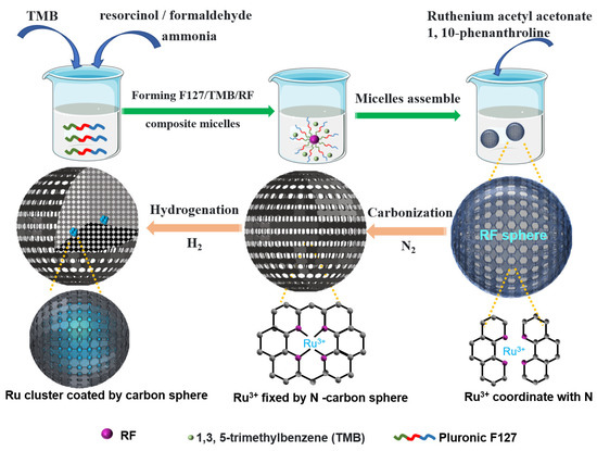
Figure 1.
Schematic illustration of the Ru@N-CS synthesis process.
In the synthesis, soft-template Pluronic F127 was dissolved into the water/ethanol/sodium chloride mixture. Then resorcinol/formaldehyde (RF) precursor, and ammonia were added into it. A two-phase system was formed by adding hydrophobic 1,3,5-trimethylbenzene (TMB). Under stirring at room temperature, large F127/TMB/RF composite micelles are formed, where emulsion droplets are first formed, then RF polymerization takes place from the inside of droplets by ammonia catalysis, and assembled with large composite micelles to form the uniform mesostructured RF resin colloidal spheres due to the H-bonding interaction with polyoxyethylene (PEO) segments of F127. The TMB molecules can mediate the self-assembly of F127 due to their strong hydrophobic effect with polyoxypropylene (PPO) segments [16] and can expand the micelle pore size due to the well-known swelling effect. As the assembly progresses, small micelles, which undergo a touching, deforming, merging, and fusing process, continuously assembled on the preformed RF nanospheres resulting in a mesoporous hollow structure [17].
Ruthenium acetyl acetonate and 1, 10-phenanthroline were dissolved into ethanol at 60 ℃ to form Ru3+ ions that coordinate with nitrogen offered by 1, 10-phenanthroline [18], which were evenly dispersed into the aforementioned F127/TMB/RF composite micelles through organic-organic co-assembly. Following carbonization in N2 atmosphere and reduction in H2/Ar atmosphere, the template agent F127 can be gradually burn off and the polymeric RF nanospheres easily converted into the carbon spheres material [19]. Finally, a stable hydrophobic mesoporous N-doped hollow carbon spheres coated Ru clusters was achieved. We call this catalyst Ru@N-CS, where the @ symbol denotes encapsulation of the clusters within the carbon spheres.
For comparison, a conventional N-doped carbon sphere supported Ru nanoparticles catalyst was prepared by impregnating Ru nanoparticles on top of preformed carbon spheres (denoted Ru/N-HC). The synthesis process was described in detail in Section 3.
The high-resolution transmission electron microscopy (HRTEM) image shows that the catalyst nanospheres structure (Figure 2a). The energy dispersive X-ray (EDX) elemental mapping images (Figure 2b) clearly show that Ru, C and N atoms are homogeneously distributed in the carbon frameworks. The Aberration-corrected scanning transmission electron microscopy in the high angle annular dark field mode (AC HAADF-STEM) image reveals that a hollow structure is formed in the middle of the carbon sphere with a particle size of 300 nm mainly (Figure 2c). A magnified STEM image and detailed observation of one Ru@N-CS clearly discloses that the mesopores are uniformly exposed in the carbon sphere (inset of Figure 2d) and the Ru clusters with particle sizes of ~1.5 nm is located in the carbon sphere (Figure 2d). HRTEM image shows that the Ru nanoparticles in the Ru/N-CS were detected on the external surface of the carbon spheres (Figure S1). By comparing the STEM of Ru@N-CS catalyst with the HRTEM of Ru/N-CS catalyst, and by referring to previous work [20], it is confirmed that Ru clusters in Ru@N-CS have been coated by carbon sphere. The high-resolution TEM selected area electron diffraction (SAED) of an individual Ru cluster presents an amorphous diffraction ring, implying a poor crystallinity of metal Ru in the Ru@N-CS (Figure 2e). The X-ray diffraction (XRD) pattern of the Ru@N-CS exhibits a broad peaks at around 24.3°, corresponding to the 002 diffraction modes of the typical graphitized carbon (Figure 2f) [21]. In addition, a diffraction peak centered at 44°, corresponding to the 002 diffraction modes of the elemental Ru clusters [22]. Inductively coupled plasma optical emission spectroscopy (ICP) reveals that the content of Ru in the Ru@N-CS catalyst was 0.015 wt% and 0.16 wt% for Ru/N-CS catalyst.
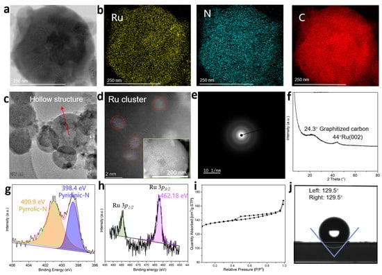
Figure 2.
Characterization of Ru@N-CS catalyst. (a), HRTEM image of Ru@N-CS. (b), Atomic-resolution EDX elemental mapping of Ru@N-CS. (c), STEM image of Ru@N-CS. (d), A magnified STEM image of Ru@N-CS. (e), A selected area electron diffraction pattern of Ru@N-CS. (f), XRD pattern of Ru@N-CS. (g), XPS spectra for N 1s of Ru@N-CS. (h), XPS spectra for Ru 3p3/2 and Ru 3p1/2 of Ru@N-CS. (i), Nitrogen adsorption–desorption isotherms of Ru@N-CS. (j), Water-droplet contact angles of Ru@N-CS.
The X-ray photoelectron spectroscopy (XPS) survey spectrum was performed to further probe the electronic structure and coordination environment of Ru atoms in the catalysts. The high-resolution N 1s XPS of Ru@N-CS spectrum can be deconvoluted into two peaks at 398.4 and 400.9 eV, corresponding to the pyridinic and pyrrolic groups, respectively (Figure 2g) [3], indicating the N-doping of the Ru@N-CS. The spectrum curves on Ru 3p3/2 (Figure 2h) revealed that the sole binding energy at 462.18 eV is associated with the Ru–Ru bond, that is, the Ru is only coordinated with Ru, confirming elemental Ru was formed [11]. In the Ru/N-CS supported catalyst, the spectrum curves on Ru 3p3/2 can be deconvoluted into two peaks, in which the Ru0 peaks at 462.24 eV and Ru4+ peak at 464.02 eV are detected, respectively (Figure S2). Correspondingly, part of the oxidized-N (content of 23.5%) exists in the Ru/N-CS catalyst (Figure S3, Table S3). The Ru@N-CS and Ru/N-CS present different Ru0 peaks, the former shows a lower bonding energy of Ru0. The typical pyridinic N peak of Ru@N-CS in the XPS spectrum is at 398.40 eV, and the pyridinic N peak of Ru/N-HC is at 398.54 eV (Figure S3). The pyridinic N in Ru@N-CS has a lower bond energy than that in Ru/N-HC. The lower the bond energy, the higher the electron density, which indicates that the pyridine N in Ru@N-CS has more electrons to transfer to Ru, and the electron-rich structure is formed on its surface. Combined with the Ru 3p and N 1s spectrum, we confirmed the N atom contributes electrons to Ru in the Ru@N-CS. Consequently, a new metal active center species, electron-rich Ru0, was created. The carbon C1s signal (284.8 eV) was used to calibrate the binding energy value (Figure S4).
Nitrogen sorption isotherms of the Ru@N-CS show typical type-IV curves in the P/P0 ranges of 0.05–0.95, clearly indicating the mesopores (Figure 2i) [23]. The pore size is centered at 3.8 nm by using the Barrett-Joyner-Halenda (BJH) method (Figure S5), which is consistent with the STEM observations. The surface area and total pore volume are calculated to be 548 m2 g−1 and 0.215 cm3 g−1, respectively. The water-droplet contact angle tests confirmed hydrophobicity (contact angle 129.5°) of the Ru@N-CS catalyst (Figure 2j).
2.2. Catalytic Performance of Phenol Hydrogenation into Cyclohexanol over Ru@N-CS Catalyst
The Ru@N-CS catalyst was evaluated in the hydrogenation of phenol in aqueous media. The blank run using N-doped carbon spheres (N-CS) without Ru failed to catalyze the reaction (Table S2). The Ru clusters were active for the phenol hydrogenation, reaching 100% conversion and a selectivity of 100% for cyclohexanol over Ru@N-CS at 80 °C, 0.5 MPa of H2, in 30 min (Figure S6, Table S1), corresponding to cyclohexanol productivity up to 471 g per gram of Ru per minute. In contrast, Ru/N-CS supported catalysts exhibited poor phenol conversion of 10% at this condition (Table S2). When the reaction time was increased to 1.5 h, the phenol was completely converted to cyclohexanol. The yield of cyclohexanol is 14.8 g per gram of Ru per minute for Ru/N-CS. Obviously, the catalytic efficiency of the Ru@N-CS catalyst is higher. Turnover of frequency (TOF) can be used to reflect the intrinsic activity of a catalyst [24,25]. The TOF value of Ru@N-CS catalyst (9880 h−1, when the conversion of phenol was 10% under 80 °C, 0.5 MPa of H2) was enhanced by 14-fold to the one of Ru/N-CS (689 h−1) (Figure 3b), indicating an ultrahigh activity of Ru@N-CS catalyst. This data also outperforms cyclohexanol productivities from phenol hydrogenation over the state-of-the-art Ru-based catalysts reported under aqueous solvent in the literature (Table S2)

Figure 3.
Study on the catalytic performance of phenol hydrogenation into cyclohexanol over Ru@N-CS catalyst. (a), Proposed reaction mechanism for hydrogenation of phenol into cyclohexanol. (b), Comparison of TOF values for Ru@N-CS catalyst and other Ru-based catalysts. (c), Recyclability tests of phenol conversion over Ru@N-CS catalyst under the conditions: 0.1 g phenol, 10 mL water, mass ratios of phenol to Ru 13,000:1, 80 °C, 0.5 MPa H2, 30 min.
Considering that the Ru@N-CS and Ru/N-CS catalysts consist of the same Ru active center and N-doped carbon spheres carrier, the distinct catalytic performances of the Ru@N-CS catalysts can be reasonably attributed to the new active species electron-rich coordination unsaturated metallic Ru, its electronic structure and coordination environment with the N-doped carbon spheres played a crucial role. The typical pyridinic N peak of Ru@N-CS (398.40 eV) in the XPS spectrum shifted to a higher binding energy compared with that of Ru/N-HC (398.54 eV). Furthermore, the semiquantitative XPS analysis of Ru@N-CS shows that pyridinic N atoms is present with 39.7 wt% (1.4-fold to the Ru/N-CS catalyst) in the carbon frameworks (Table S3). According to the Mott–Schottky effect [26], it demonstrated that the lonepair electrons of the pyridinic N in N-doped carbon spheres partially transferred to Ru clusters to form the electronic-rich Ru for Ru@N-CS. This electron transfer confirmed the synergistic effect of the Ru cores and N-doped carbon spheres. In addition, the pyridinic N is confirmed to be connected with catalytic activity because it electronically interacted with Ru to enhance the hydrogenation activity and stability, which led to a significant enhancement of the catalytic activity of the Ru@N-CS and benefited the phenol hydrogenation [27,28]. The X-ray photoelectron spectroscopy (XPS) reveal that the electron-rich and coordination-unsaturated Ru species were obtained.
The Ru@N-CS catalyst was tested for 7 consecutive cycles of catalytic phenol hydrogenation, and no decline in activity was observed. The conversion rate of phenol decreased to 94%, and the selectivity of cyclohexanol remains 100% after the 8th cycle. (Figure 3c). HRTEM and STEM image of the spend catalyst (8 cycles) showed that there are no obvious structural changes, which excluded the inactivation caused by structural changes (Figure S7). ICP result showed that there is 8% leaching amount. The decrease in metal content could result in deactivation of catalyst. The experimental result shows that the Ru/N-CS catalyst prepared by universal impregnation method suffered from severe leaching, the leaching amount of Ru was 38% (measured by ICP) after five cycles (Figure S8). Furthermore, the HRTEM image of spend Ru/N-CS catalyst (5 cycles) showed Ru nanoparticles were agglomerated (Figure S9). Therefore, the inactivation of Ru/N-CS catalyst was due to metal leaching and agglomeration. The cycling stability of Ru@N-CS catalyst was remarkably superior to that of Ru/N-CS catalyst and other Ru-based catalysts reported in the literature (Table S2). The significant advantages of Ru@N-CS catalyst was reasonably due to the uniformly distributed small Ru clusters protected by hydrophobic properties of carbon spheres. CO chemisorption measurement of the Ru@N-CS revealed the dispersion was as high as 87% of Ru within the carbon spheres support and the average size of the clusters amount to 1.5 nm. As a contrast, the dispersion of Ru nanoparticles in Ru/N-CS catalyst was only 39%, and the particle size was increased to unequal of 3.0–6.0 nm (Figure S1). The smaller Ru clusters (~1.5 nm) would improve the metal utilization, boosting the activity [7]. The highly dispersed metallic sites have been widely addressed to control the number of adsorption sites and their intrinsic catalytic properties. Furthermore, the Ru clusters in Ru@N-CS catalyst might be stabilized for modulated the electronic properties by N heteroatom because their lonepair electrons can serve as metal coordination sites, strengthening the metal-support interaction between the encapsulated Ru clusters and the carbon sphere, hindering agglomerating phenomena and leaching [29]. However, for the supported Ru/N-CS catalyst, it can be understood that Ru nanoparticles supported on the surface of carbon spheres due to the lack of interaction between Ru nanoparticles and carbon sphere, resulting in catalyst leaching and then inactivation.
To acquire a clearer picture of the reactions that works in this process, we analyzed the intermediates during the reaction under the conditions of 80 °C, 0.5 MPa of H2. In the process of reaction, phenol conversion increased with time, cyclohexanone appeared as the intermediate, which was further fast hydrogenated to form the final product cyclohexanol in 30 min (Figure S10). We confirmed that phenol hydrogenation proceeds via the tandem steps of (1) C=C bonds in phenol hydrogenated to form cyclohexanone and (2) cyclohexanone hydrogenated by H2 to form cyclohexanol (Figure S11). Our investigation demonstrates that once the hydrogenation of phenol starts, the nonpolar phenol is easily absorbed by hydrophobic carbon spheres, enhancing its concentration in the catalytic sites. At the same time, the hydrophobic hydrogen molecules can easily pass through the hydrophobic mesoporous carbon spheres to access the Ru clusters. With the increase of reaction time, more phenol diffused into the Ru sites and reached saturation. Phenol-cyclohexanol competitive sorption feature shifts cyclohexanol product to the aqueous solution from within the mesoporous hydrophobic carbon spheres once formed. Since cyclohexanol product has a weaker non-polarity relative to the phenol and it can easily diffuse through the hydrophobic carbon spheres, which benefits the selective hydrogenation of phenol. The reaction mechanism for hydrogenation of phenol into cyclohexanol is proposed as shown in Figure 3a. Clearly, highly dispersed electron-rich Ru clusters coated by superhydrophobic carbon spheres enhance phenol conversion.
To better understand the intrinsic activities of Ru@N-CS catalysts for the phenol hydrogenation, the reaction kinetic study on the phenol hydrogenation was conducted by analyzing the initial reaction rate at different temperatures (60–80 °C) and reaction time (2–10 min) under hydrogen pressure of 0.5 MPa (Figure S12). The linear relationship between –ln(1–x) (x represents the conversion of phenol) and reaction time indicates that the hydrogenation reaction of phenol into cyclohexanol follows the first-order reaction kinetics [4,30]. The evident diminution in apparent activation energy (Ea) over Ru@N-CS (33.8 kJ mol−1) catalyst to the other metal catalysts [28,31,32,33] (Table S4) is believed to be attributed to the electron coordination effect between Ru clusters and N-doped carbon sphere, which increases the electron density of the metal Ru through partial sharing of lonepair electron in pyridinic N. Thereby, prompting an overall reactant rate (Figure S13).
2.3. Density Functional Theory (DFT) Calculation
To understand the mechanism of hydrogenation of phenol into cyclohexanol on metal surfaces, we investigated the adsorption energies and preferred adsorption geometries by DFT calculations [34,35]. As revealed from the kinetic experimental results mentioned above and catalyst characterization (XRD, HRTEM and STEM) results, a Ru cluster coated by N-doped carbon (Ru1: undercoordinated electron-rich Ru) model was considered for theoretical calculations (Figure 4a). In comparison, a Ru (002) (Ru2) slab model was investigated (Figure 4b). When H2 is adsorbed on Ru1 site, it is dissociated to active species H atom (Figure 4a). The lower the decomposition energy, the easier the reaction is. From the calculation results in the Table 1, it can be seen that Ru@N-CS system is beneficial to reduce the decomposition energy of H2.
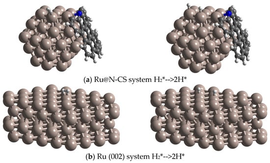
Figure 4.
The optimized structures of (a) Ru@N-CS system H2*-->2H*, (b) Ru (002) surface H2*-->2H*.

Table 1.
The calculated H2 decomposition energy barrier (eV) on Ru@N-CS and Ru (002).
Figure 5 shows the most stable adsorption configurations of phenol, intermediate product of cyclohexanone, and product of cyclohexanol on Ru1, respectively. Phenol was found to be the most stable adsorption configuration with the ring closely parallel to the (002) plane of Ru1 and the hydroxyl group tilted away from the surface (Figure 5a). Parallel adsorption geometry for phenol on Ru1 results in interaction of phenol with four surface Ru atoms. The ΔEads for phenol is −1.52 eV (Table 2), which is higher than that of the Ru2 (−1.37 eV) (Table 3). Cyclohexanone was found to be oriented perpendicular to the Ru1 surface through the carbonyl O atom, and interacted with surface sites only (Figure 5b). The adsorption energy of −0.73 eV (Table 2) was much lower than that of Ru2 (−0.93 eV) (Table 3).
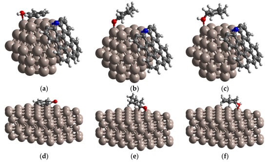
Figure 5.
The optimized structures of (a) phenol, (b) cyclohexanone, (c) cyclohexanol adsorbed on Ru@N-CS surface; (d) phenol, (e) cyclohexanone, (f) cyclohexanol adsorbed on Ru (002) surface.
Table 2.
The calculated phenol, cyclohexanone, cyclohexanol adsorption energy on Ru@N-CS system, unit: eV.
Table 3.
The calculated phenol, cyclohexanone, cyclohexanol adsorption energy on Ru (002) surface, unit: eV.
These results reveal that Ru1 could remarkably increase the adsorption energy for phenol, and therefore significantly increase the reaction property. This could be attributed to the superhydrophobic characteristics of the catalyst carrier, which makes the non-polar phenol easily passing through carbon spheres and then is adsorbed by undercoordinated electron-rich Ru active site in Ru@N-CS system. The different adsorption configurations were obtained for cyclohexanol (Figure 5c). Cyclohexanol adsorbs on Ru1 through the hydroxyl O atom, with the ring being parallel to the surface. Compared with phenol and cyclohexanone, cyclohexanol has the lowest adsorption energy, with ΔEads = −0.64 eV (Table 2). Therefore, the polar product cyclohexanol is easier to desorbed from Ru1 active site and diffuse into aqueous solution through hydrophobic carbon.
3. Materials and Methods
3.1. Materials
Pluronic F127, 1,3,5-trimethylbenzene (TMB), ammonia, sodium chloride (NaCl), resorcinol, formaldehyde solution, ruthenium acetyl acetone, 1,10-phenanthroline, and ethanol were purchased from Sigma-Aldrich. All reagents were commercially obtained without purification.
3.2. Synthesis of Mesoporous Hollow Carbon Spheres
The superhydrophobic mesoporous hollow carbon spheres were synthesized via an organic-organic assembly approach. Typically, 0.8 g of Pluronic F127, 0.15 g of resorcinol, 0.2 mL of formaldehyde solution, and 0.8 mL of TMB were continuously added into a mixture solution of water (40 mL), ethanol (50 mL) and 0.08 g NaCl and stirred at 100 rpm to form large F127/TMB/RF composite micelles. Next, 0.05 mL of ammonia solution was added to induce the polymerization of RF molecules and self-assembly into the intermediated mesoporous RF cores. After stirring at room temperature for 24 h, the well-developed mesoporous hollow RF spheres were collected by centrifugation and then washed with water and ethanol five times. After calcination at 350 °C for 180 min and then at 850 °C at a rate of 1 °C min−1 for 60 min in N2 atmosphere, the mesoporous carbon nanospheres were obtained with mesostructured.
3.3. Synthesis of Mesoporous Hollow Ru@N-CS Catalyst
As a typical run for synthesis of Ru@N-CS, 0.1 g of ruthenium acetyl acetone and 0.2 g of 1, 10-phenanthroline were dissolved within 40 mL of ethanol at 80 °C, then the aforementioned RF molecules solution was added into it. The mixture was stirred for 24 h at room temperature. After centrifuging, washing with ethanol five times, drying at 60 °C in the air, calcination at 350 °C for 180 min and at 850 °C at a rate of 1 °C min−1 for 60 min in N2 atmosphere, and then at 350 °C for 180 min in H2 atmosphere, the Ru@N-CS was obtained. The Ru clusters were embedded within mesoporous carbon nanospheres.
3.4. Synthesis of Ru/N-CS Catalyst
The Ru/N-CS was synthesized by traditional impregnation method. As a typical run, 0.1 g of ruthenium acetyl acetone and 0.2 g of 1,10-phenanthroline were dissolved within 40 mL of ethanol at 80 °C, then the aforementioned mesoporous carbon nanospheres was added into it. The mixture was stirred at room temperature for 24 h. After centrifuging, washing with ethanol five times, drying at 60 °C in the air, and then reduction at 350 °C for 180 min in H2 atmosphere, the Ru/N-CS was obtained. The Ru nanoparticles were supported on the surface of carbon nanospheres.
3.5. Characterization Method of Catalysts
Powder X-ray diffraction (XRD) patterns were detected by a Bruker D8-Focus diffractometer system using a Cu Kα radiation (λ = 0.15418 nm, 40 kV and 40 mA) in the range of 10–80° with a scan speed of 5° min−1. The specific surface area and pore structure data were carried out by Autosorb Station 2. Before the test, all samples were outgassed at 100 °C for 1 h and 300 °C for another 3 h. The specific surface area of catalyst was calculated by the Brunauer-Emmett-Teller (BET) method; the pore size distribution was calculated using the Barret-Jovner-Halenda (BJH) method and DFT method. The actual loading of copper in catalysts was examined with the inductively coupled plasma optical emission spectrometry (ICP-OES) using iCAP 7400. The morphology features of the catalysts were studied by a high-resolution transmission electron microscopy (HRTEM) on a Hitachi S-4800 and an aberration-corrected scanning transmission electron microscopy in the high angle annular dark field mode (AC HAADF-STEM) on a Titan 80−300 scanning/transmission electron microscope operated at 300 kV. The energy dispersive spectrometer (EDS) was performed on a Hitachi S-4800 electron microscopy (JEOL, Japan) with an acceleration voltage of 200 kV. X-ray photoelectron spectra (XPS) was carried out on a ThermoFisher Scientific ESCALAB Xi+ spectrometer with Al Kα X-ray radiation. The carbon C1s signal (284.8 eV) was used to calibrate the binding energy value. A semiqualitative analysis of metallic to higher oxidation state ratio of Ru was carried out based on full width at half-maxima and the area under the curve in XPS peaks [36]. The contact angle of water droplets on the solid surface were measured on an Optical Contact Angle Meter (SL200KB). CO chemisorption measurements were carried out at room temperature using a Micromeritics Instrument Corporation—AutoChem II 2910 V5.02.
3.6. Catalytic Hydrogenation Measurements of Phenol into Cyclohexanol
The series of catalytic experiments of phenol hydrogenation were carried out in a 50 mL batch stainless steel high-pressure reactor fitted with a magnetic stirring and a quartz liner. A mixture of phenol (0.1 g), Ru@N-CS catalysts (0.05 g), and water (10 mL) were added to the autoclave with a stirring rate of 800 rpm. The reactor was purged 3 times with N2. The desired amount of 0.5 MPa H2 was charged into the reactor when the temperature reached 80 °C. The reaction time was set as to be 30 min. When the reaction was stopped, the liquid product was taken out immediately by relief valve intermediate sampler. In addition, then the liquid samples were cooled down to room temperature. The conversion rate of phenol was quantitatively analyzed on a gas chromatograph (GC, Agilent 6820) equipped with a capillary column HP-5 (60 m × 0.32 mm × 0.25 μm) and a flame ionization detector. GC test conditions: injection temperature 260 °C, program heating steps: initial temperature 80 °C, 10 °C min−1 up to 280 °C, and the detector temperature is 280 °C. Diethylene glycol dimethyl ether was selected as the internal standard. The identification of the product was performed by using a GC-MS (Shimazu. Japan, GC/MS-QP2010) equipped with a capillary column DB-5ms (30 m × 0.25 μm × 0.25 nm). GC-MS test conditions: injection temperature 260 °C, program heating steps: initial temperature 80 °C, 10 °C min−1 up to 280 °C.
The conversion of phenol and selectivity of cyclohexanol product were calculated by the following equation.
The final concentration of phenol was calculated by the internal standard method of GC-MS, and the standard curves under different conversion rates of phenol were shown in Figures S12 and S13.
The cycling tests of phenol hydrogenation over Ru@N-CS were carried out. After a reaction, the catalyst could be separated from the reaction aqueous system by filtration, dried, and reused in a subsequent run.
3.7. Calculation on Reaction Rate Constant (k) and Activation Energy (Ea)
To better investigate the reaction rate of phenol hydrogenation over Ru@N-NC catalysts, the conversion of phenol at different temperature (60–80 °C) was carried out. The conversion of phenol increases linearly with the reaction time at different temperatures. It is also noted that the reaction rate (the slope of the line) is also increased with the increasing temperature (Figure S14). The reaction rate k of phenol hydrogenation into cyclohexanol at a certain temperature was calculated according to the following equation:
When the Equation (1) was integrated, it becomes the following equation.
where [phenol] is the molar concentrations of phenol, t is the reaction time, and k is the reaction rate, x is the LA conversion.
As shown in Figure S15, the apparent activation energies (Ea) of phenol hydrogenation can be calculated by the Arrhenius equation according to the reaction rate at different temperatures.
where k is the reaction rate of phenol hydrogenation into cyclohexanol at a certain temperature, A is a pre-exponential factor, R is molar gas constant of 8.314 J mol−1 K−1, and T is the reaction temperature [K].
3.8. DFT Computational Details
Density functional theory periodic slab calculations were carried out using the Vienna Ab Initio Simulation Package (VASP) [37]. The generalized gradient approximation (GGA) with the Perdew-Burke-Ernzerhof (PBE) functional were used to describe the electronic exchange and correlation effects [38,39]. Uniform G-centered k-points meshes with a resolution of 2π*0.04 Å−1 and Methfessel-Paxton electronic smearing were adopted for the integration in the Brillouin zone for geometric optimization. The simulation was run with a cutoff energy of 450 eV throughout the computations. These settings ensure convergence of the total energies to within 10 meV per atom. Structure relaxation proceeded until all forces on atoms were less than 10 meV Å−1 and the total stress tensor was within 0.03 GPa of the target value. Due to the importance of dispersion forces in describing the Ru surfaces with organic molecule, the semi-empirical correction by Grimme (DFT + D3) was included [40,41].
The adsorption energy of phenol, cyclohexanone, cyclohexanol on Ru@N-CS and Ru (002) surfaces was calculated by the following equation:
which E(total), E(surface), E(molecule) represent the energy of phenol, cyclohexanone, cyclohexanol absorbed on Ru@N-CS and Ru (002) surfaces, energy of the Ru@N-CS and Ru (002) surfaces and energy of the phenol, cyclohexanone, cyclohexanol molecules, respectively. The more negative the adsorption energy, the more stable the adsorption.
ΔEads = E(total) − E(surface) − E(molecule)
4. Conclusions
In summary, we have demonstrated the encapsulation of highly dispersed active Ru clusters (~1.5 nm in size) inside N-doped hollow mesoporous carbon spheres with hydrophobic properties. This results in a hydrophobic carbon sphere reactor with high local adsorption of phenol in aqueous solution and an ultra-active electron-rich Ru species, which considerably enhance efficient hydrogenation of phenol and selectivity to cyclohexanol. We believe that carbon spheres with hydrophobic property act as powerful supports for metal Ru clusters, because of the electron coordination effect. This work represents a large step toward the upgrading of bio-oil, especially of lignin-derivative compounds, and lays a theoretical foundation for the industrialization of high value-added chemicals from lignin-derivative compounds catalytic hydrogenation conversion under mild aqueous phase conditions.
Supplementary Materials
The following supporting information can be downloaded at: https://www.mdpi.com/article/10.3390/catal12090995/s1.
Author Contributions
Conceptualization, Y.W. and M.Y.; methodology, S.W.; software, X.L.; validation, Y.W.; formal analysis, S.W.; investigation, S.W. and J.W.; data curation, S.W., X.L. and J.W.; writing—original draft preparation, S.W.; writing—review and editing, S.W. All authors have read and agreed to the published version of the manuscript.
Funding
This research was funded by National Key R&D Program of China, 2018YFC1902101; National Natural Science Foundation of China, 21838006.
Data Availability Statement
The data that support the plots within this paper are available from the corresponding author on reasonable request.
Acknowledgments
All the authors thank Yu for his contribution to DFT calculation.
Conflicts of Interest
The authors declare no conflict of interest.
References
- Corma, A.S.; Iborra, A. Chemical routes for the transformation of biomass into chemicals. Chem. Rev. 2007, 107, 2411–2502. [Google Scholar] [CrossRef] [PubMed]
- Xue, G.; Yin, L.; Shao, S.; Li, G. Recent progress on selective hydrogenation of phenol toward cyclohexanone or cyclohexanol. Nanotechnology 2021, 33, 072003. [Google Scholar] [CrossRef] [PubMed]
- Cui, X.; Surkus, A.E.; Junge, K.; Topf, C.; Radnik, J.; Kreyenschulte, C.; Beller, M. Highly selective hydrogenation of arenes using nanostructured ruthenium catalysts modified with a carbon-nitrogen matrix. Nat. Commun. 2016, 7, 11326. [Google Scholar] [CrossRef] [PubMed]
- Wang, H.; Zhao, W.; Rehman, M.; Liu, W.; Xu, Y.; Huang, H.; Wang, S.; Zhao, Y.; Mei, D.; Ma, X. Copper Phyllosilicate Nanotube Catalysts for the Chemosynthesis of Cyclohexane via Hydrodeoxygenation of Phenol. ACS Catal. 2022, 12, 4724–4736. [Google Scholar] [CrossRef]
- Barta, K.; Ford, P.C. Catalytic Conversion of Nonfood Woody Biomass Solids to Organic Liquids. Acc. Chem. Res. 2014, 47, 1503–1512. [Google Scholar] [CrossRef]
- Long, J.; Shu, S.; Wu, Q.; Yuan, Z.; Wang, T.; Xu, Y.; Zhang, X.; Zhang, Q.; Ma, L. Selective cyclohexanol production from the renewable lignin derived phenolic chemicals catalyzed by Ni/MgO. Energy Convers. Manag. 2015, 105, 570–577. [Google Scholar] [CrossRef]
- Song, Z.; Ren, D.; Wang, T.; Jin, F.; Jiang, Q.; Huo, Z. Highly selective hydrothermal production of cyclohexanol from biomass-derived cyclohexanone over Cu powder. Catal. Today 2016, 274, 94–98. [Google Scholar] [CrossRef]
- Saidi, M.; Samimi, F.; Karimipourfard, D.; Nimmanwudipong, T.; Gates, B.C.; Rahimpour, M. Upgrading of lignin-derived bio-oils by catalytic hydrodeoxygenation. Energy Environ. Sci. 2014, 7, 103–129. [Google Scholar] [CrossRef]
- Mondelli, C.; Gözaydın, G.; Yan, N.; Pérez-Ramírez, J. Biomass valorisation over metal-based solid catalysts from nanoparticles to single atoms. Chem. Soc. Rev. 2020, 49, 3764–3782. [Google Scholar] [CrossRef]
- Davda, R.R.; Shabaker, J.W.; Huber, G.W.; Cortright, R.D.; Dumesic, J.A. A review of catalytic issues and process conditions for renewable hydrogen and alkanes by aqueous-phase reforming of oxygenated hydrocarbons over supported metal catalysts. Appl. Catal. B Environ. 2005, 56, 171–186. [Google Scholar] [CrossRef]
- Zhan, J.; Hu, R.; Luo, X.; Zhang, C.; Luo, G.; Fan, J.; Clark, J.; Zhang, S. Highly selective conversion of phenol to cyclohexanol over Ru/Nb2O5-nC18PA catalysts with increased acidity in a biphasic system under mild conditions. Green Chem. 2022, 24, 1152–1164. [Google Scholar] [CrossRef]
- Karakhanov, E.; Maximov, A.; Zolotukhina, A.; Mamadli, A. Dendrimer-Stabilized Ru Nanoparticles Immobilized in Organo-Silica Materials for Hydrogenation of Phenols. Catalysts 2017, 7, 86. [Google Scholar] [CrossRef]
- Peng, L.; Peng, H.; Hung, C.-T.; Guo, D.; Duan, L.; Ma, B.; Liu, L.; Li, W.; Zhao, D. Programmable synthesis of radially gradient-structured mesoporous carbon nanospheres with tunable core-shell architectures. Chem 2021, 7, 1020–1032. [Google Scholar] [CrossRef]
- Tian, H.; Liang, J.; Liu, J. Nanoengineering Carbon Spheres as Nanoreactors for Sustainable Energy Applications. Adv. Mater. 2019, 31, 1903886. [Google Scholar] [CrossRef]
- Liu, J.; Yang, T.; Wang, D.-W.; Lu, G.; Zhao, D.; Qiao, S. A facile soft-template synthesis of mesoporous polymeric and carbonaceous nanospheres. Nat. Commun. 2013, 4, 2798. [Google Scholar] [CrossRef]
- Tang, J.; Liu, J.; Li, C.; Li, Y.; Tade, M.O.; Dai, S.; Yamauchi, Y. Synthesis of nitrogen-doped mesoporous carbon spheres with extra-large pores through assembly of diblock copolymer micelles. Angew. Chem. Int. Ed. Engl. 2015, 54, 588–593. [Google Scholar] [CrossRef]
- Liu, J.; Qiao, S.; Liu, H.; Chen, J.; Orpe, A.; Zhao, D.; Lu, G. Extension of the Stober method to the preparation of monodisperse resorcinol-formaldehyde resin polymer and carbon spheres. Angew. Chem. Int. Ed. 2011, 50, 5947–5951. [Google Scholar] [CrossRef] [PubMed]
- Gao, Y.; Wu, T.; Yang, C.; Ma, C.; Zhao, Z.; Wu, Z.; Cao, S.; Geng, W.; Wang, Y.; Yao, Y. Activity Trends and Mechanisms in Peroxymonosulfate-Assisted Catalytic Production of Singlet Oxygen over Atomic Metal-N-C Catalysts. Angew. Chem. Int. Ed. 2021, 60, 22513–22521. [Google Scholar] [CrossRef]
- Xu, F.; Tang, Z.; Huang, S.; Chen, L.; Liang, Y.; Mai, W.; Zhong, H.; Fu, R.; Wu, D. Facile synthesis of ultrahigh-surface-area hollow carbon nanospheres for enhanced adsorption and energy storage. Nat. Commun. 2015, 6, 7221. [Google Scholar] [CrossRef]
- Yu, Z.; Ji, N.; Xiong, J.; Li, X.; Zhang, R.; Zhang, L.; Lu, X. Ruthenium-Nanoparticle-Loaded Hollow Carbon Spheres as Nanoreactors for Hydrogenation of Levulinic Acid: Explicitly Recognizing the Void-Confinement Effect. Angew. Chem. Int. Ed. Engl. 2021, 60, 20786–20794. [Google Scholar] [CrossRef]
- Liu, D.; Zhang, L.; Han, W.; Tang, M.; Zhou, L.; Zhang, Y.; Li, X.; Qin, Z.; Yang, H. One-step fabrication of Ni-embedded hierarchically-porous carbon microspheres for levulinic acid hydrogenation. Chem. Eng. J. 2019, 369, 386–393. [Google Scholar] [CrossRef]
- Zhuang, Z.; Wang, Y.; Xu, C.; Liu, S.; Chen, C.; Peng, Q.; Zhuang, Z.; Xiao, H.; Pan, Y.; Lu, S. Three-dimensional open nano-netcage electrocatalysts for efficient pH-universal overall water splitting. Nat. Commun. 2019, 10, 4875. [Google Scholar] [CrossRef]
- Li, A.; Shen, K.; Chen, J.; Li, Z.; Li, Y. Highly selective hydrogenation of phenol to cyclohexanol over MOF-derived non-noble Co-Ni@NC catalysts. Chem. Eng. Sci. 2017, 166, 66–76. [Google Scholar] [CrossRef]
- Vinokurov, V.; Glotov, A.; Chudakov, Y.; Stavitskaya, V.; Ivanov, E.; Gushchin, P.; Zolotukhina, A.; Maximov, A.; Karakhanov, E.; Lvov, Y. Core/Shell Ruthenium–Halloysite Nanocatalysts for Hydrogenation of Phenol. Ind. Eng. Chem. Res. 2017, 56, 14043–14052. [Google Scholar] [CrossRef]
- Singh, N.; Lee, M.; Akhade, S.A.; Cheng, G.; Camaioni, D.M.; Gutierrez, O.Y.; Glezakou, V.A.; Rousseau, R.; Lercher, J.A.; Campbell, C.T. Impact of pH on Aqueous-Phase Phenol Hydrogenation Catalyzed by Carbon-Supported Pt and Rh. ACS Catal. 2018, 9, 1120–1128. [Google Scholar] [CrossRef]
- Su, H.; Zhang, K.; Zhang, B.; Wang, H.; Yu, Q.; Li, X. Activating Cobalt Nanoparticles via the Mott-Schottky Effect in Nitrogen-Rich Carbon Shells for Base-Free Aerobic Oxidation of Alcohols to Esters. J. Am. Chem. Soc. 2017, 139, 811–818. [Google Scholar] [CrossRef] [PubMed]
- Shi, J.; Zhao, M.; Wang, Y.; Fu, J.; Lu, X.; Hou, Z. Upgrading of aromatic compounds in bio-oil over ultrathin graphene encapsulated Ru nanoparticles. J. Mater. Chem. A 2016, 4, 5842–5848. [Google Scholar] [CrossRef]
- Guo, H.; Gao, R.; Sun, M.; Guo, H.; Wang, B.; Chen, L. Cobalt Entrapped in N,S-Codoped Porous Carbon: Catalysts for Transfer Hydrogenation with Formic Acid. ChemSusChem 2019, 12, 487–494. [Google Scholar] [CrossRef]
- Chen, Z.; Zeng, X.; Wang, S.; Cheng, A.; Zhang, Y. Advanced Carbon-Based Nanocatalysts and their Application in Catalytic Conversion of Renewable Platform Molecules. ChemSusChem 2022, 15, 202200411. [Google Scholar] [CrossRef]
- Qian, W.; Lin, L.; Qiao, Y.; Zhao, X.; Xu, Z.; Gong, H.; Li, D.; Chen, M.; Huang, R.; Hou, Z. Ru subnanoparticles on N-doped carbon layer coated SBA-15 as efficient Catalysts for arene hydrogenation. Appl. Catal. A Gen. 2019, 585, 117183. [Google Scholar] [CrossRef]
- Zhao, C.; Kasakov, S.; He, J.; Lercher, J.A. Comparison of kinetics, activity and stability of Ni/HZSM-5 and Ni/Al2O3-HZSM-5 for phenol hydrodeoxygenation. J. Catal. 2012, 296, 12–23. [Google Scholar] [CrossRef]
- Resende, K.A.; Hori, C.E.; Noronha, F.B.; Shi, H.; Gutierrez, O.Y.; Camaioni, D.M.; Lercher, J.A. Aqueous phase hydrogenation of phenol catalyzed by Pd and PdAg on ZrO2. Appl. Catal. A Gen. 2017, 548, 128–135. [Google Scholar] [CrossRef]
- He, L.; Niu, Z.; Miao, R.; Chen, Q.; Guan, Q.; Ning, P. Selective hydrogenation of phenol by the porous Carbon/ZrO2 supported Ni Co nanoparticles in subcritical water medium. J. Clean. Prod. 2019, 215, 375–381. [Google Scholar] [CrossRef]
- Liu, Z.; Hamad, I.; Li, Y.; Chen, Y.; Wang, S.; Jentoft, R.; Jentoft, F.C. Poisoning and competitive adsorption effects during phenol hydrogenation on platinum in water-alcohol mixtures. Appl. Catal. A Gen. 2019, 585, 117199. [Google Scholar] [CrossRef]
- Liu, D.; Li, G.; Yang, F.; Wang, H.; Han, J.; Zhu, X.; Ge, Q. Competition and Cooperation of Hydrogenation and Deoxygenation Reactions during Hydrodeoxygenation of Phenol on Pt(111). J. Phys. Chem. C 2017, 121, 12249–12260. [Google Scholar] [CrossRef]
- Khan, T.S.; Singh, D.; Samal, P.P.; Krishnamurty, S.; Dhepe, P.L. Mechanistic Investigations on the Catalytic Transfer Hy-drogenation of Lignin-Derived Monomers over Ru Catalysts: Theoretical and Kinetic Studies. ACS Sustain. Chem. Eng. 2021, 9, 14040–14050. [Google Scholar] [CrossRef]
- Kresse, G.; Furthmüller, J. Efficiency of ab-initio total energy calculations for metals and semiconductors using a plane-wave basis set. Comput. Mater. Sci. 1996, 6, 15–50. [Google Scholar] [CrossRef]
- Perdew, J.P.; Burke, K.; Ernzerhof, M. Generalized Gradient Approximation Made Simple. Phys. Rev. Lett. 1996, 77, 3865–3868. [Google Scholar] [CrossRef]
- Blöchl, P.E. Projector augmented-wave method. Phys. Rev. B Condens. Matter Mater. Phys. 1994, 50, 17953–17979. [Google Scholar] [CrossRef]
- Davis, J.B.A.; Baletto, F.; Johnston, R.L. The Effect of Dispersion Correction on the Adsorption of CO on Metallic Nano-particles. J. Phys. Chem. A 2015, 119, 9703–9709. [Google Scholar] [CrossRef] [Green Version]
- Grimme, S.; Antony, J.; Ehrlich, S.; Krieg, H. System-Dependent Dispersion Coefficients for the DFT-D3 Treatment of Adsorption Processes on Ionic Surfaces. ChemPhysChem 2011, 12, 3414–3420. [Google Scholar]
Publisher’s Note: MDPI stays neutral with regard to jurisdictional claims in published maps and institutional affiliations. |
© 2022 by the authors. Licensee MDPI, Basel, Switzerland. This article is an open access article distributed under the terms and conditions of the Creative Commons Attribution (CC BY) license (https://creativecommons.org/licenses/by/4.0/).