Article

In Situ Growth and UV Photocatalytic Effect of ZnO Nanostructures on a Zn Plate Immersed in Methylene Blue

by
Ranjitha K. Hariharalakshmanan
1,*,
Fumiya Watanabe
2 and
Tansel Karabacak
1
1
School of Physical Sciences, University of Arkansas at Little Rock, Little Rock, AR 72204, USA
2
Center for Integrative Nanotechnology Sciences, University of Arkansas at Little Rock, Little Rock, AR 72204, USA
*
Author to whom correspondence should be addressed.
Catalysts 2022, 12(12), 1657; https://doi.org/10.3390/catal12121657
Submission received: 31 October 2022 / Revised: 1 December 2022 / Accepted: 6 December 2022 / Published: 16 December 2022
(This article belongs to the Special Issue Nanomaterials for Photocatalysis and Piezo-Photocatalysis)

Abstract

:
Nanostructures of zinc oxide (ZnO) are considered promising photocatalysts for the degradation of organic pollutants in water. This work discusses an in situ growth and UV photocatalytic effect of ZnO nanostructures on a Zn plate immersed in methylene blue (MB) at room temperature. First, the Zn surfaces were pretreated via sandblasting to introduce a micro-scale roughness. Then, the Zn plates were immersed in MB and exposed to UV light, to observe ZnO nanostructure growth and photocatalytic degradation of MB. Scanning electron microscopy, energy dispersive spectroscopy, X-ray diffraction, X-ray photoelectron spectroscopy, and UV-Vis diffuse reflectance spectroscopy were used to characterize the Zn surfaces. We observed the growth of stoichiometric and crystalline ZnO with a nano-leaf morphology and an estimated bandgap of 3.08 eV. The photocatalytic degradation of MB was also observed in the presence of the ZnO nanostructures and UV light. The average percentage degradation was 76% in 4 h, and the degradation rate constant was 0.3535 h−1. The experimental results suggest that room temperature growth of ZnO nanostructures (on Zn surfaces) in organic dye solutions is possible. Furthermore, the nanostructured surface can be used simultaneously for the photocatalytic degradation of the organic dye.

1. Introduction

Semiconductor photocatalysis and its application in water pollutant degradation have been the subject of extensive research over the past two decades [1,2]. It involves the absorption of light by a semiconductor, the generation of electron-hole pairs, and subsequent redox reactions that produce free radicals also known as reactive oxygen species (ROS) [3,4,5]. ROS are utilized to mineralize water contaminants; hence the process aids the complete degradation of contaminants rather than just physical separation [6]. Nano-sized metal oxides have been widely studied for this application [7,8]. TiO2 is the most popular metal oxide photocatalyst owing to its optoelectronic properties, stability, and relative non-toxicity [9,10,11]. Another metal oxide that is comparable to TiO2 is ZnO [5,12]. ZnO is an n-type wide bandgap semiconductor (3.37 eV) with a high exciton binding energy at room temperature, and high electron mobility. It is also non-toxic, low-cost, and abundant [5].
Researchers have used various methods to synthesize ZnO nanostructures [13]. These methods can be broadly categorized into solution-based and vapor phase methods. Some examples of solution-based methods are sol-gel [14], hydrothermal [15,16], electrochemical deposition [17,18], and coprecipitation [19]. In these methods, the morphology and size of the nanostructures can be controlled by various experimental parameters, types of solvents, and reaction conditions [12,17]. Solution-based methods are simple and less energy consuming than the vapor phase methods, such as physical vapor deposition, chemical vapor deposition, thermal evaporation, and pulsed laser deposition [12]. However, both categories involve precursor chemicals, high temperatures, and/or vacuum systems, which can be costly, energy consuming, and toxic to the environment.
In recent years, there has been much interest in environmentally benign nanostructure synthesis methods [20]. Especially in nano-photocatalysis, where the intended application is environmental remediation, it is desired that their synthesis approaches do not involve the use of toxic chemicals [21]. Additionally, ZnO nano-photocatalyst synthesis methods need to be cost-effective to promote their wide-spread use in water treatment. This means the synthesis methods should be simple and not require expensive equipment [21]. One such green nanostructure approach is the hot water treatment (HWT) method which simply involves the immersion of metal surfaces in hot deionized (DI) water [22]. In a previous work, we reported the synthesis of ZnO nanostructures by HWT of Zn and its use for the photocatalytic degradation of methylene blue (MB) [23]. One of the significant advantages of this method is that it does not require any chemical additives [22]. In addition, the temperature used in HWT (75–95 °C) is much lesser than the conventional nanostructure synthesis methods [22]. Another precursor-free and water-based ZnO nanostructure synthesis method is the submerged photosynthesis of crystallites (SPSC) reported by Jeem et al. [24] and Zhang et al. [25]. They showed that ZnO nanostructures could be synthesized just by the immersion of Zn plates in room temperature DI water and exposure to UV light. They used a submerged liquid plasma process as a surface pretreatment to introduce ZnO seed layers, which initiated the nanostructure growth process [24,25]. The growth process involved hydrothermal as well as photoinduced reactions [24,25].
This work is inspired by the SPSC process and investigates if ZnO nanostructure growth can occur in situ in the organic dye solution, which one wants to degrade via photocatalysis. In other words, we designed a single-step approach where the photocatalyst synthesis and its application happen simultaneously. For this, we immersed a Zn plate in an aqueous MB solution at room temperature and exposed it to UV light. We used a simple and low-cost sandblasting process as a surface pretreatment, which introduced micro-scale roughness on our Zn surfaces [26]. Our results show that leaf-shaped ZnO nanostructures are formed when Zn surfaces are immersed in MB. We did not observe a significant difference in the nanostructure growth with or without UV light. Nevertheless, we observed the degradation of MB due to the photocatalytic activity of the nanostructures. The main advantages of this nano-photocatalyst synthesis method are that it does not require high temperatures or any chemical additives, and it is simple, low-cost, and environmentally friendly. Moreover, the ZnO nanostructures in our photocatalyst design are attached to the Zn surface. Researchers have given much emphasis to the immobilization of photocatalysts to avoid agglomeration of the nanostructures, secondary pollution, and nanostructure reclamation from the water, which could be expensive [27,28]. Our method achieves photocatalyst immobilization in a single step. The materials characterization, possible growth mechanisms, and photocatalytic performance of the ZnO nanostructures are discussed.

2. Results and Discussion

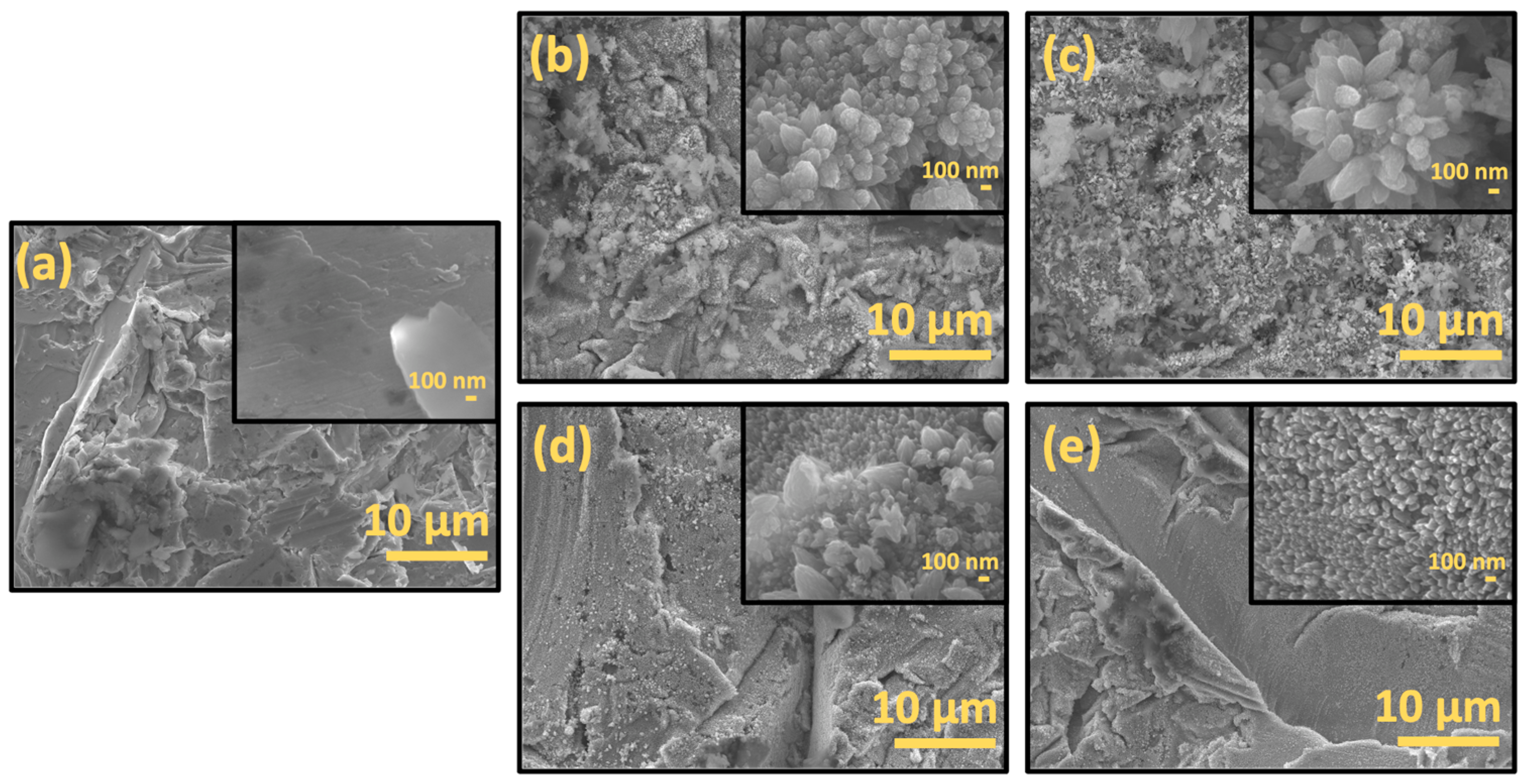
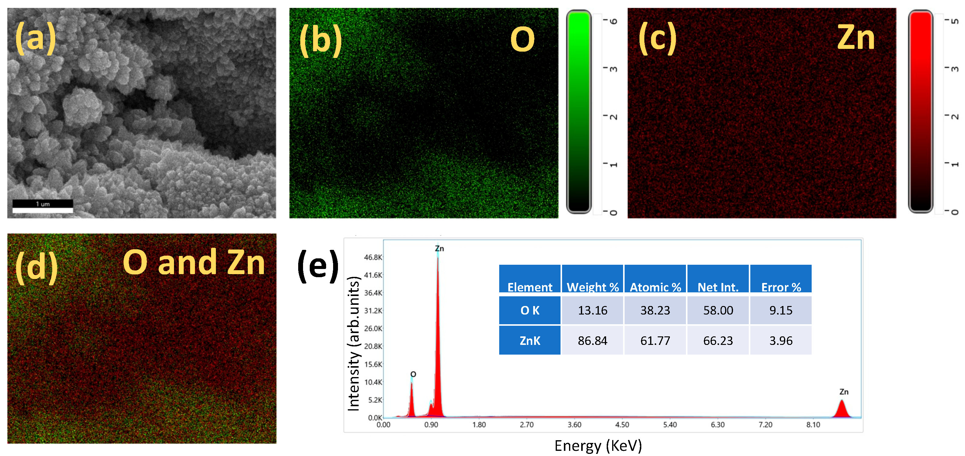
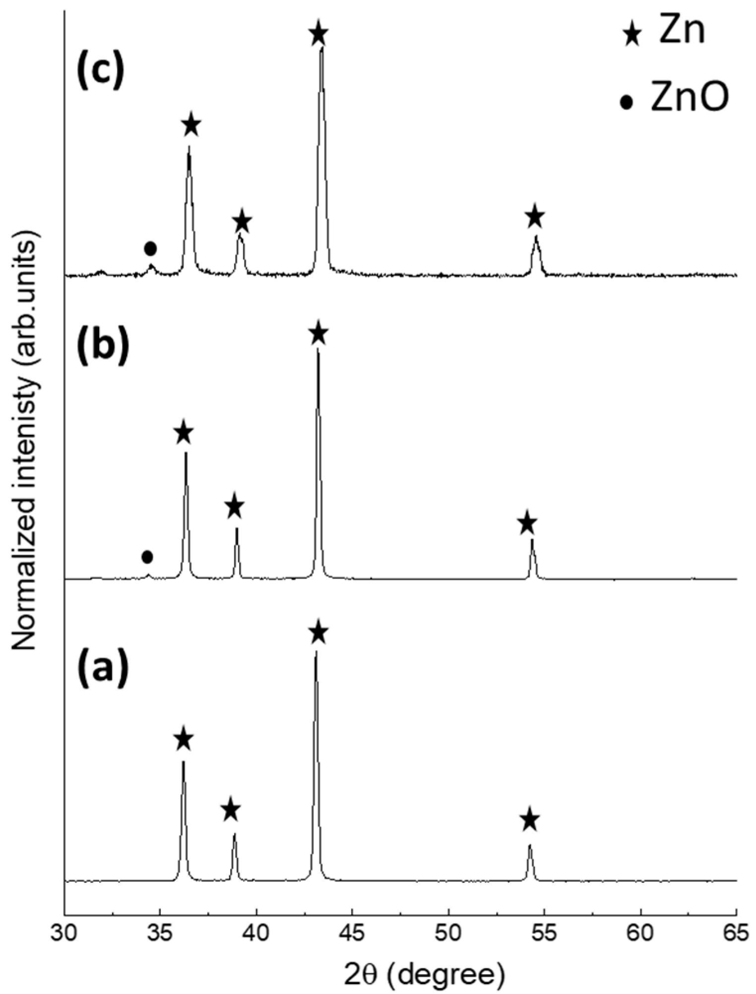
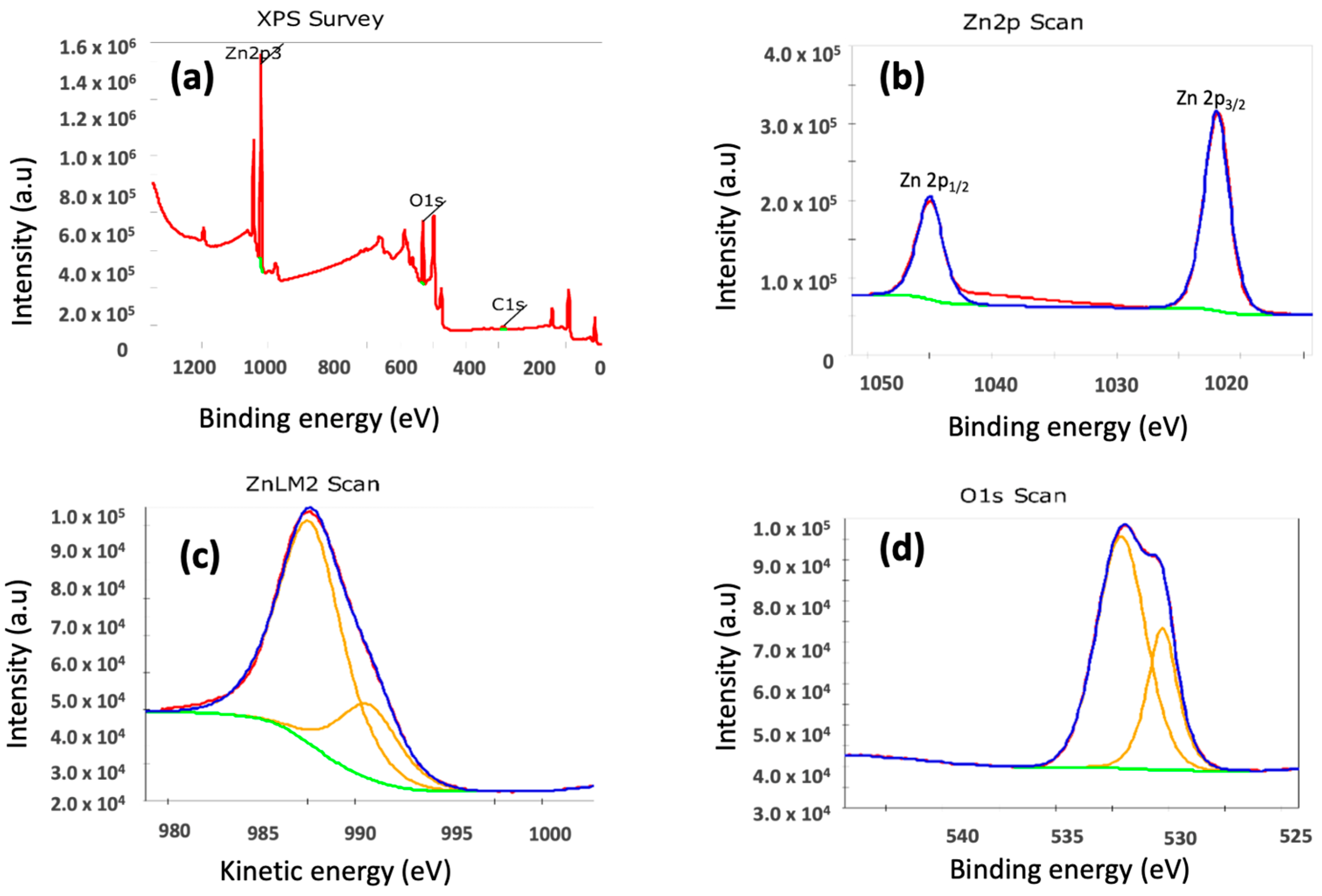
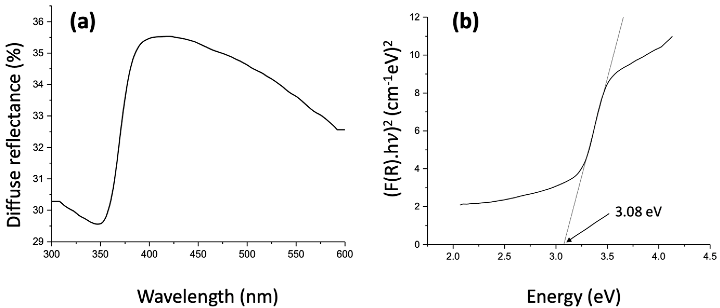
2.1. Materials Charecterization

Scanning electron microscopy (SEM) was used to investigate the Zn plate surface before and after its immersion in MB solution. The micro-scale roughness introduced on the Zn surface by sandblasting can be observed in Figure 1a. Figure 1b,c show the formation of leaf-shaped ZnO nanostructures on the Zn surface after it was immersed in MB for 4 h, with and without UV irradiation, respectively. In both samples, the nanostructures had approximate lengths ranging from 300 to 600 nm and widths ranging from 150 to 250 nm. Low magnification images of both samples show some irregular structures, which could be amorphous Zn(OH)2. Overall, the sample surfaces are uniformly covered with leaf-shaped nanostructures. Figure 1d,e show the ZnO nanostructures grown on Zn surfaces immersed in pure DI water, with and without UV light, respectively.
The morphology of the nanostructures grown in DI water is the same as in MB. However, the density of nanostructure growth is less in DI water, both in the presence and absence of UV light. Most of the DI water nanostructures had lengths ranging from 100 to 200 nm and widths ranging from 50 to 200 nm, but some structures with sizes similar to those grown in MB were also observed. The comparison of ZnO nanostructure growth in the two mediums (MB and DI water) and the presence and absence of UV light are further discussed in Section 2.2.
Energy dispersive X-ray spectroscopy (EDS) was used to analyze the chemical composition of the Zn surfaces. EDS mapping of the ZnO nanostructures grown in MB with UV light showed an even distribution of Zn and O (Figure 2a–d), indicating the growth of stoichiometric ZnO. The higher atomic percentage of Zn is most likely due to the underlying Zn plate (Figure 2e). The compositional analysis of the irregularly shaped structures showed a higher O ratio, possibly due to Zn(OH)2 (Figure S1). The EDS results of Zn surfaces immersed in MB in the dark, and DI water with and without UV light showed a similar chemical composition (Figures S2–S4).
X-ray diffraction (XRD) was used to analyze the crystal structure of the ZnO nanostructures. Figure 3a shows the XRD profile of the sandblasted Zn surface before its immersion into MB. The peaks centered at 36.2°, 38.9°, 43.1°, and 54.2° could be attributed to (002), (100), (101), and (102) crystal planes of Zn (crystallography open database entry 9008522). After 4 h of immersion in MB, we observed the appearance of a peak at 34.4°, which can be attributed to the (002) crystal plane of hexagonal wurtzite ZnO (crystallography open database entry 1011258). No other peaks were observed; hence, we could not confirm the presence of Zn(OH)2 from XRD.
X-ray photoelectron spectroscopy (XPS) was used to analyze the surface chemical composition of the samples. Figure 4a shows the XPS survey spectrum of the Zn surface immersed in MB and exposed to UV light for 4 h. Figure 4b shows the Zn 2p XPS spectrum. Since the Zn 2p3/2 peaks of elemental Zn and ZnO are very close, it is difficult to distinguish between elemental Zn and ZnO on the sample. Hence, Auger Zn LMM spectrum of the sample was obtained (Figure 4c) [29]. The Auger peak could be fitted to two peaks centered at kinetic energies of 987.6 eV and 990.4 eV [29]. The former is attributed to ZnO and the latter to elemental Zn. Thus, XPS also confirmed the formation of ZnO nanostructures on the surface of the Zn plate. The O 1s spectrum (Figure 4d) of the sample could be fitted to two peaks, one centered at 530.29 eV and the other at 532.11 eV. The lower binding energy peak is attributed to O2− in the stoichiometric wurtzite ZnO lattice, whereas the higher binding energy peak can be attributed to OH or H2O groups attached to Zn [30]. Hence, the XPS analysis also indicates the presence of Zn(OH)2 on the sample, which could be the irregularly shaped white layers observed in the SEM images [25,29].
The optical bandgap of the ZnO nanostructures was estimated using UV-Vis diffuse reflectance spectroscopy, Kubelka-Munk function (F(R)), and Tauc plot [31,32]. The diffuse reflectance measurement of the ZnO nanostructures synthesized by the immersion of Zn plates in MB and exposed to UV light for 4 h is shown in Figure 5a. F(R) is given by Equation (1), where α is the absorption coefficient, s is the scattering coefficient, and R is the diffuse reflectance. Here, we assume that s does not depend on wavelength and is, therefore, a constant. The absorption coefficient is related to the bandgap according to the Tauc equation (Equation (2)). Here, h is Planck’s constant, ν is the frequency, A is a constant, Eg is the bandgap energy, and n is ½ for direct bandgap. Hence, the Tauc equation could be rewritten as Equation (3). Figure 5b shows the graph plotted according to Equation (3). The optical bandgap of the ZnO nanostructures was estimated by extrapolating the linear portion of the plot to the x-axis, where (F(R).hν)2 is zero. The value of the bandgap obtained from the plot was 3.08 eV, which is lower compared to the bandgap of bulk ZnO (3.37 eV). Further investigation needs to be done to determine the reason for the lower bandgap; however, it could be due to defects in the ZnO nanostructures [33,34].
F ( R ) = α s = ( 1 R ) 2 2 R
( α h ν   ) 1 / n = A ( h ν Eg )
( F ( R ) . h ν   ) 2 = A ( h ν Eg )

2.2. Nanostructure Growth Mechanism

The chemical reactions involved in the room-temperature growth of ZnO nanostructures on a Zn plate are explained by Jeem et al. [24] and Zhang et al. [25]. In their work, both hydrothermal (Equations (4)–(8)) and photoinduced reactions (Equations (9)–(13)) were involved in the synthesis of ZnO nanostructures. The latter produced OH·, which converted into OH, which is important for the formation of ZnO [25].
Zn → Zn2+ + 2e
2H2O + 2e → H2 + 2OH
Zn2+ + 2OH → Zn(OH)2
Zn(OH)2 + 2OH → Zn(OH)42−
Zn(OH)42− → ZnO + 2OH + H2O
ZnO + hv → e + h+
H2O + h+ → OH· + H+
ZnO + H2O + 2h+ → Zn2+ + 2OH·
e → eaq
OH· + eaq → OH
In our work, the SEM images show that ZnO nanostructure growth in MB is very similar in the presence and absence of UV light. Based on this, we assume that hydrothermal reactions are dominant during ZnO nanostructure growth in our study. Reactions (1) and (2) are the anodic (oxidation) and cathodic (reduction) reactions, respectively, involved in the corrosion of Zn metal in water [25]. We believe that the micro-rough surface created by sandblasting acts as a corrosion micro-cell, as described by Zhang et al. [25]. In the experiments involving UV light, we observe the degradation of MB. This indicates that light does produce hydroxyl radicals. However, they do not seem to participate in the growth of ZnO, at least in this experiment duration (4 h). Longer treatment times may yield different results [24,25], which will be explored in future studies.
We also want to address two other observations from our experiments. The first one is the presence of Zn(OH)2 on our sample surfaces as indicated by EDS and XPS analysis. According to the chemical reactions listed above, Zn(OH)2 is formed as an intermediate during the formation of ZnO. The conversion of Zn(OH)2 to ZnO requires an alkaline environment. Hence, Zn(OH)2 could persist on the sample surface if enough OH were not available for it to form ZnO [25,35]. Another observation is the enhancement in nanostructure growth in MB compared to in DI water. Wang et al. have reported that the presence of organic dyes can affect the growth direction of ZnO nanostructures during hydrothermal synthesis [36]. Their results show that the presence of anionic dyes during the growth of ZnO nanowires led to a reduction in the growth of ZnO nanowires along the c-axis. This was due to the electrostatic attraction between the dye anions and the Zn2+ ions [36]. We hypothesize that the presence of dissolved MB cations in the vicinity of the Zn surface could be responsible for the electrostatic attraction of more OH ions. This could increase the interactions between Zn2+ and OH and thus enhance the growth of ZnO.

2.3. Photocatalytic Degradation of Methylene Blue

Figure 6 shows the normalized concentration (C/C0) of MB vs. time plot during different degradation experiments. The curves show average C/C0 values from three experiments, and their standard deviations are shown in the error bars. Please see Figures S5–S7 for the UV-Vis profiles from all experiments. There was no change in MB concentration before and after the 30 min stirring in the dark. Two control experiments were performed, one where only MB was exposed to UV light and the other where the Zn plate was immersed in MB but not exposed to UV light. MB degradation was negligible in both scenarios. These results show that the degradation observed when Zn plates were immersed in MB and exposed to UV light is due to the photocatalytic effect of the ZnO nanostructures on the surface of the Zn plate. The average percentage degradation of MB is 76% in 4 h. According to the Langmuir-Hinshelwood mechanism, photocatalytic degradation can be modeled as pseudo-first order reaction described by the equation Ln(C0/C) = kt, where k is the degradation rate constant. Hence, Ln(C0/C) was plotted against time and linearly fitted to find the degradation rate constant from the slope, which is 0.3535 h−1.
Florica et al. [37] reported a similar study in which ZnO nanowires were synthesized by a precursor-free thermal oxidation method on Zn foils and were used for the photocatalytic degradation of MB. They reported a percentage degradation of 57% in 320 min and a degradation rate constant of 0.1542 h−1. However, it is worth mentioning that comparing photocatalyst performances based only on degradation percentage and rate constant is not the best practice. Various other factors affect a photocatalyst’s performance, such as its morphology and crystal structure, the wavelength and intensity of the light source, and the type, concentration, pH, and volume of the organic dye used in the experiments [17,38,39,40,41]. Table 1 shows some works that reported the synthesis of ZnO nanostructures that are immobilized on various surfaces. The photocatalytic degradation of MB and some other organic dyes are also shown. We have limited this table to pure ZnO nanostructures and excluded reports that modified ZnO nanostructures by doping or forming heterojunctions with other materials.
Here, we acknowledge that various methods can control the morphology [42], crystal structure [17,43,44], bandgap [45,46,47], and defects [48,49] of ZnO nanostructures by altering the reaction conditions, thereby fine-tune its photocatalytic performance. The main distinction of this work is that ZnO nanostructures are synthesized on a micro-rough Zn plate without using any chemical additives, precursors, or high temperatures. Moreover, photocatalyst synthesis and its application for photocatalytic dye degradation co-occur, which makes this process extremely simple and less energy consuming. This result is of significant importance in the current scenario of increased interest in cost-effective, energy-efficient, and environmentally friendly nanostructure synthesis methods for photocatalytic applications.
Table 1. Different methods to synthesize ZnO nanostructures immobilized on different surfaces and their photocatalytic degradation performances.
ZnO SynthesisOrganic Dye
Solution (Type, Volume,
Concentration)
Light Source (Wavelength and Power) Best Photocatalytic Performance or Rate Constant Ref.
MethodNanostructures immobilized on Materials usedReaction parameters
Hydrothermal Si and glassZinc acetate, zinc nitrate, hexamethylenetetramine60–150 °C, 13 h (approx.)Methylene Blue, 12 mL, 10 mMFluorescent lamp, 375 nm, 18 Watts45% in 6 h, 0.0021 min−1[50]
HydrothermalPDMS/PETZinc acetate, zinc nitrate, hexamethylenetetramine60–90 °C, 10 h (approx.)Methylene Blue, 40 mL, 10 mMFluorescent lamp, 375 nm, 18 Watts50% degradation in 6 h, 0.0018 min−1[51]
Thermal oxidationZn Nil500 °C, 12 hMethylene Blue, 35 × 10−6 MUV lamp, 312 nm, 15 Watts57% degradation in 320 min, 0.1542 h−1[37]
Spray pyrolysis FTO coated glassZinc acetate, methanol425 °CMethylene Blue, volume not reported, 1 mMUV light, wavelength and power not reported 98.1% degradation in 120 min, rate constant not reported [52]
AnodizationZn Potassium bicarbonate, orthophosphoric acid, hydrochloric acid, oxalic acid, and sodium hydroxide 10–40 V DC for anodization, pre and post treatment annealing at 300 °C. Phenol, 50 mL, 5 ppmUV lamp, 254 nm, 6 Watts82% degradation in 4 h, 0.44 h−1[17]
Anodization and O2 plasma annealing Zn Potassium bicarbonate1 V DC, pretreatment annealing at 300 °C and post treatment thermal and O2. plasma annealing (200–350 °C)Phenol, 50–80 mL, 5–10 ppmUV lamp, 254 nm, 6 Watts70% degradation in 4 h, 0.31 h−1 [35]
Hydrothermal ZnZinc nitrate, hexamethylenetetramine, methylamine, potassium hydroxide 120–180 °C, 2–12 hRhodamine B, 10 mL, 1 × 10⁻⁵ MUV lamp, wavelength and power not reported 80% degradation of rhodamine B in 3 h, rate constant not reported[15]
One of the limitations of this work is that the ZnO nanostructure growth mechanism is not fully understood. In a future study, we will investigate the how the ZnO nanostructure growth is affected by the time of immersion of the Zn plates in MB. It is important to understand if the nanostructures continue to grow during longer immersion times, which may alter their photocatalytic performance. We will also investigate the effect of concentration, pH, and type of organic dye on the photocatalytic activity, as well as the photocatalytic degradation mechanism. We also plan to test the durability of the nanostructures against photocorrosion. Understanding the growth mechanism and durability determines the long-term reusability of the ZnO nanostructures which is crucial for photocatalytic water treatment applications.

3. Materials and Methods

3.1. ZnO Nanostructure Synthesis

Zn plates (Purchased from amazon.com, USA, manufacturer name: LTKJ Ltd.) of 99.9% purity and 0.3 mm thickness were cut into pieces of dimension 25 mm × 25 mm. Sandpaper of size p3000 was used to clean any surface contamination on the plates. Then, the Zn plates were sandblasted using Al2O3 abrasives of size 120 grit at a pressure of 80 psi to introduce micro-scale roughness on the plate surface. After sandblasting, they were cleaned by ultrasonication in acetone, isopropyl alcohol, and DI water for 10 min each. After this, the Zn plates were immersed in an aqueous solution of methylene blue (SPI supplies, West Chester, PA, USA) (50 mL) at a concentration of 2.5 ppm (mg/L) contained in a glass beaker. The solution was stirred for 30 min in the dark using a magnetic stirring bar to establish adsorption–desorption equilibrium. Then, the Zn plates and MB were irradiated with 254 nm UV light from an 8-Watt UV lamp fixed at a vertical distance of 15 cm, for 4 h. Three control experiments were conducted to investigate the effects of UV light and MB on the ZnO nanostructure growth: (1) Zn plates were immersed in MB and left in the dark for 4 h, (2) Zn plates were immersed in pure DI water and exposed to UV light, and (3) Zn plates were immersed in pure DI water and left in the dark for 4 h. In all experiments, MB/DI water was continuously stirred throughout the experiment and a cold-water bath was used to prevent the increase in water temperature in the beaker.

3.2. Materials Characterization

SEM (JOEL JSM-7000F, Tokyo, Japan ) along with EDS (EDAX Element, Pleasanton, CA, USA) were used to analyze the morphology and map the chemical composition of the Zn surfaces. XRD (Rigaku Miniflex 600, Tokyo, Japan) was used to analyze the crystal structure, XPS (Thermo Scientific K-Alpha, Waltham, MA, USA) was used to investigate the surface chemical states of the samples. The sample surfaces were etched for 10 s, to clean the surfaces before XPS analysis. UV-Vis diffuse reflectance spectroscopy (Shimadzu UV-3600, Kyoto, Japan) was used to estimate the bandgap of the ZnO nanostructures.

3.3. In Situ Photocatalytic Degradation Experiment

The concentration of MB at regular intervals of time was measured using UV-Vis absorbance spectroscopy (Agilent Carry 60, Santa Clara, CA, USA). A total of 3 mL of MB was retrieved from the as-prepared solution, after 30 min of stirring in dark, and every hour after the UV light was switched on. Beer-Lambert law was used to estimate the concentration of MB from the UV-Vis peak (at 664 nm) absorbance values. If C0 represents the initial concentration of MB and C, the concentration at a particular time, the percentage degradation of MB was calculated using ((C − C0)/C0) × 100 [53].

4. Conclusions

Zn plates were immersed in an aqueous solution of MB, and an in situ ZnO nanostructure growth and UV photocatalytic effect were investigated. Leaf-shaped ZnO nanostructures were formed on the surface of the Zn plate both in the presence and absence of UV light. In the presence of UV, the ZnO nanostructures acted as a photocatalyst and degraded MB. The average MB degradation was 76% in 4 h. The results show that nanostructured ZnO photocatalysts could be synthesized simply by the immersion of Zn plates in MB solutions, without any chemical additives or heating. Hence, this is a low-cost, low-energy, and environmentally benign method to synthesize ZnO nanostructures for photocatalytic applications.

Supplementary Materials

The following supporting information can be downloaded at: https://www.mdpi.com/article/10.3390/catal12121657/s1, Figure S1: (a) SEM image and (b–d) corresponding EDS maps of irregularly shaped ZnO nanostructures grown on Zn surface in MB and with UV light, and (e) elemental composition of the same. Figure S2: (a) SEM image and (b–d) corresponding EDS maps of ZnO nanostructures grown on Zn surface in MB and without UV light, and (e) elemental composition of the same. Figure S3: (a) SEM image and (b–d) corresponding EDS maps of ZnO nanostructures grown on Zn surface in DI water and with UV light, and (e) elemental composition of the same. Figure S4: (a) SEM image and (b–d) corresponding EDS maps of ZnO nanostructures grown on Zn surface in DI water and without UV light, and (e) elemental composition of the same. Figure S5: Time dependent UV-Vis spectra of MB with ZnO nanostructures and UV light. Figure S6: Time dependent UV-Vis spectra of MB with ZnO nanostructures without UV light. Figure S7: Time dependent UV-Vis spectra of MB with UV light only.

Author Contributions

Conceptualization, R.K.H. and T.K.; methodology, R.K.H. and T.K.; validation, R.K.H., F.W. and T.K.; formal analysis, R.K.H., F.W. and T.K.; writing—original draft preparation, R.K.H.; writing—review and editing, F.W. and T.K.; visualization, R.K.H.; supervision, T.K.; funding acquisition R.K.H. and T.K. All authors have read and agreed to the published version of the manuscript.

Funding

The project was supported in part by Arkansas Research Alliance (award number: AWD-100664) and Arkansas Space Grant Consortium (award number: AWD-242034).

Data Availability Statement

All data are contained in the article and the supplementary material.

Acknowledgments

CINS: UA Little Rock for their support with SEM and XPS analysis.

Conflicts of Interest

The authors declare no conflict of interest. The funders had no role in the design of the study; in the collection, analyses, or interpretation of data; in the writing of the manuscript, or in the decision to publish the results.

References

  1. Loeb, S.K.; Alvarez, P.J.J.; Brame, J.A.; Cates, E.L.; Choi, W.; Crittenden, J.; Dionysiou, D.D.; Li, Q.; Li-Puma, G.; Quan, X.; et al. The Technology Horizon for Photocatalytic Water Treatment: Sunrise or Sunset? Environ. Sci. Technol. 2019, 53, 2937–2947. [Google Scholar] [CrossRef] [Green Version]
  2. Rafiq, A.; Ikram, M.; Ali, S.; Niaz, F.; Khan, M.; Khan, Q.; Maqbool, M. Photocatalytic degradation of dyes using semiconductor photocatalysts to clean industrial water pollution. J. Ind. Eng. Chem. 2021, 97, 111–128. [Google Scholar] [CrossRef]
  3. Ren, G.; Han, H.; Wang, Y.; Liu, S.; Zhao, J.; Meng, X.; Li, Z. Recent Advances of Photocatalytic Application in Water Treatment: A Review. Nanomaterials 2021, 11, 1804. [Google Scholar] [CrossRef]
  4. Liu, X.; Ruan, W.; Wang, W.; Zhang, X.; Liu, Y.; Liu, J. The Perspective and Challenge of Nanomaterials in Oil and Gas Wastewater Treatment. Molecules 2021, 26, 3945. [Google Scholar] [CrossRef]
  5. Batra, V.; Kaur, I.; Pathania, D.; Sonu; Chaudhary, V. Efficient dye degradation strategies using green synthesized ZnO-based nanoplatforms: A review. Appl. Surf. Sci. Adv. 2022, 11, 100314. [Google Scholar] [CrossRef]
  6. Chong, M.N.; Jin, B.; Chow, C.W.K.; Saint, C. Recent developments in photocatalytic water treatment technology: A review. Water Res. 2010, 44, 2997–3027. [Google Scholar] [CrossRef]
  7. Danish, M.S.S.; Estrella, L.L.; Alemaida, I.M.A.; Lisin, A.; Moiseev, N.; Ahmadi, M.; Nazari, M.; Wali, M.; Zaheb, H.; Senjyu, T. Photocatalytic Applications of Metal Oxides for Sustainable Environmental Remediation. Metals 2021, 11, 80. [Google Scholar] [CrossRef]
  8. Mondal, K.; Sharma, A. Recent advances in the synthesis and application of photocatalytic metal–metal oxide core–shell nanoparticles for environmental remediation and their recycling process. RSC Adv. 2016, 6, 83589–83612. [Google Scholar] [CrossRef]
  9. Schneider, J.; Matsuoka, M.; Takeuchi, M.; Zhang, J.; Horiuchi, Y.; Anpo, M.; Bahnemann, D.W. Understanding TiO2 Photocatalysis: Mechanisms and Materials. Chem. Rev. 2014, 114, 9919–9986. [Google Scholar] [CrossRef]
  10. Guo, Q.; Zhou, C.; Ma, Z.; Yang, X. Fundamentals of TiO2 Photocatalysis: Concepts, Mechanisms, and Challenges. Adv. Mater. 2019, 31, 1901997. [Google Scholar] [CrossRef]
  11. Marinho, B.A.; de Souza, S.; de Souza, A.A.U.; Hotza, D. Electrospun TiO2 nanofibers for water and wastewater treatment: A review. J. Mater. Sci. 2021, 56, 5428–5448. [Google Scholar] [CrossRef]
  12. Ong, C.B.; Ng, L.Y.; Mohammad, A.W. A review of ZnO nanoparticles as solar photocatalysts: Synthesis, mechanisms and applications. Renew. Sustain. Energy Rev. 2018, 81, 536–551. [Google Scholar] [CrossRef]
  13. Sanakousar, F.M.; Vidyasagar, C.C.; Jiménez-Pérez, V.M.; Prakash, K. Recent progress on visible-light-driven metal and non-metal doped ZnO nanostructures for photocatalytic degradation of organic pollutants. Mater. Sci. Semicond. Process. 2022, 140, 106390. [Google Scholar] [CrossRef]
  14. Ba-Abbad, M.M.; Kadhum, A.A.H.; Mohamad, A.B.; Takriff, M.S.; Sopian, K. Optimization of process parameters using D-optimal design for synthesis of ZnO nanoparticles via sol–gel technique. J. Ind. Eng. Chem. 2013, 19, 99–105. [Google Scholar] [CrossRef]
  15. Wang, L.; Zheng, Y.; Li, X.; Dong, W.; Tang, W.; Chen, B.; Li, C.; Li, X.; Zhang, T.; Xu, W. Nanostructured porous ZnO film with enhanced photocatalytic activity. Thin Solid Films 2011, 519, 5673–5678. [Google Scholar] [CrossRef]
  16. Liu, Y.; Kang, Z.H.; Chen, Z.H.; Shafiq, I.; Zapien, J.A.; Bello, I.; Zhang, W.J.; Lee, S.T. Synthesis, Characterization, and Photocatalytic Application of Different ZnO Nanostructures in Array Configurations. Cryst. Growth Des. 2009, 9, 3222–3227. [Google Scholar] [CrossRef]
  17. Ramirez-Canon, A.; Medina-Llamas, M.; Vezzoli, M.; Mattia, D. Multiscale design of ZnO nanostructured photocatalysts. Phys. Chem. Chem. Phys. 2018, 20, 6648–6656. [Google Scholar] [CrossRef] [Green Version]
  18. Anand, V.; Srivastava, V.C. Zinc oxide nanoparticles synthesis by electrochemical method: Optimization of parameters for maximization of productivity and characterization. J. Alloys Compd. 2015, 636, 288–292. [Google Scholar] [CrossRef]
  19. Kumar, V.R.; Wariar, P.R.S.; Prasad, V.S.; Koshy, J. A novel approach for the synthesis of nanocrystalline zinc oxide powders by room temperature co-precipitation method. Mater. Lett. 2011, 65, 2059–2061. [Google Scholar] [CrossRef]
  20. Agarwal, H.; Venkat Kumar, S.; Rajeshkumar, S. A review on green synthesis of zinc oxide nanoparticles-An eco-friendly approach. Resour.-Effic. Technol. 2017, 3, 406–413. [Google Scholar] [CrossRef]
  21. Khatami, M.; Iravani, S. Green and Eco-Friendly Synthesis of Nanophotocatalysts: An Overview. Comments Inorg. Chem. 2021, 41, 133–187. [Google Scholar] [CrossRef]
  22. Saadi, N.S.; Hassan, L.B.; Karabacak, T. Metal oxide nanostructures by a simple hot water treatment. Sci. Rep. 2017, 7, 7158. [Google Scholar] [CrossRef] [Green Version]
  23. Hariharalakshmanan, R.K.; Saadi, N.S.; Ergul-Yilmaz, B.; Al-Mayalee, K.H.; Karabacak, T. Zinc Oxide Nanostructures Synthesized by a Simple Hot Water Treatment Method for Photocatalytic Degradation of Organic Pollutants in Water. MRS Adv. 2020, 5, 2457–2465. [Google Scholar] [CrossRef]
  24. Jeem, M.; bin Julaihi, M.R.M.; Ishioka, J.; Yatsu, S.; Okamoto, K.; Shibayama, T.; Iwasaki, T.; Kato, T.; Watanabe, S. A pathway of nanocrystallite fabrication by photo-assisted growth in pure water. Sci. Rep. 2015, 5, 11429. [Google Scholar] [CrossRef] [PubMed] [Green Version]
  25. Zhang, L.; Jeem, M.; Okamoto, K.; Watanabe, S. Photochemistry and the role of light during the submerged photosynthesis of zinc oxide nanorods. Sci. Rep. 2018, 8, 177. [Google Scholar] [CrossRef] [PubMed] [Green Version]
  26. Hassan, L.B.; Saadi, N.S.; Karabacak, T. Hierarchically rough superhydrophobic copper sheets fabricated by a sandblasting and hot water treatment process. Int. J. Adv. Manuf. Technol. 2017, 93, 1107–1114. [Google Scholar] [CrossRef]
  27. Le, A.T.; Le, T.D.H.; Cheong, K.-Y.; Pung, S.-Y. Immobilization of zinc oxide-based photocatalysts for organic pollutant degradation: A review. J. Environ. Chem. Eng. 2022, 10, 108505. [Google Scholar] [CrossRef]
  28. Navidpour, A.H.; Hosseinzadeh, A.; Zhou, J.L.; Huang, Z. Progress in the application of surface engineering methods in immobilizing TiO2 and ZnO coatings for environmental photocatalysis. Catal. Rev. 2021, 1–52. [Google Scholar] [CrossRef]
  29. Zinc X-ray Photoelectron Spectra, Zinc Electron Configuration, and Other Elemental Information. Available online: https://www.thermofisher.com/us/en/home/materials-science/learning-center/periodic-table/transition-metal/zinc.html (accessed on 28 October 2022).
  30. Pantò, F.; Dahrouch, Z.; Saha, A.; Patanè, S.; Santangelo, S.; Triolo, C. Photocatalytic degradation of methylene blue dye by porous zinc oxide nanofibers prepared via electrospinning: When defects become merits. Appl. Surf. Sci. 2021, 557, 149830. [Google Scholar] [CrossRef]
  31. Al-Mayalee, K.H.; Saadi, N.; Badradeen, E.; Watanabe, F.; Karabacak, T. Optical and Photoconductive Response of CuO Nanostructures Grown by a Simple Hot-Water Treatment Method. J. Phys. Chem. C 2018, 122, 23312–23320. [Google Scholar] [CrossRef]
  32. Makuła, P.; Pacia, M.; Macyk, W. How To Correctly Determine the Band Gap Energy of Modified Semiconductor Photocatalysts Based on UV–Vis Spectra. J. Phys. Chem. Lett. 2018, 9, 6814–6817. [Google Scholar] [CrossRef] [PubMed] [Green Version]
  33. Nandi, P.; Das, D. Morphological variations of ZnO nanostructures and its influence on the photovoltaic performance when used as photoanodes in dye sensitized solar cells. Sol. Energy Mater. Sol. Cells 2022, 243, 111811. [Google Scholar] [CrossRef]
  34. Wahyuono, R.A.; Hermann-Westendorf, F.; Dellith, A.; Schmidt, C.; Dellith, J.; Plentz, J.; Schulz, M.; Presselt, M.; Seyring, M.; Rettenmeyer, M.; et al. Effect of annealing on the sub-bandgap, defects and trapping states of ZnO nanostructures. Chem. Phys. 2017, 483–484, 112–121. [Google Scholar] [CrossRef]
  35. Taylor, C.M.; Ramirez-Canon, A.; Wenk, J.; Mattia, D. Enhancing the photo-corrosion resistance of ZnO nanowire photocatalysts. J. Hazard. Mater. 2019, 378, 120799. [Google Scholar] [CrossRef] [PubMed]
  36. Wang, H.; Cai, Y.; Wang, C.; Xu, H.; Fang, J.; Yang, Y. Seeded growth of ZnO nanowires in dye-containing solution: The submerged plant analogy and its application in photodegradation of dye pollutants. CrystEngComm 2020, 22, 4154–4161. [Google Scholar] [CrossRef]
  37. Florica, C.; Costas, A.; Preda, N.; Beregoi, M.; Kuncser, A.; Apostol, N.; Popa, C.; Socol, G.; Diculescu, V.; Enculescu, I. Core-shell nanowire arrays based on ZnO and CuxO for water stable photocatalysts. Sci. Rep. 2019, 9, 17268. [Google Scholar] [CrossRef] [Green Version]
  38. Reza, K.M.; Kurny, A.S.W.; Gulshan, F. Parameters affecting the photocatalytic degradation of dyes using TiO2: A review. Appl. Water Sci. 2017, 7, 1569–1578. [Google Scholar] [CrossRef] [Green Version]
  39. Chen, X.; Wu, Z.; Liu, D.; Gao, Z. Preparation of ZnO Photocatalyst for the Efficient and Rapid Photocatalytic Degradation of Azo Dyes. Nanoscale Res. Lett. 2017, 12, 143. [Google Scholar] [CrossRef] [Green Version]
  40. Xu, L.; Hu, Y.-L.; Pelligra, C.; Chen, C.-H.; Jin, L.; Huang, H.; Sithambaram, S.; Aindow, M.; Joesten, R.; Suib, S.L. ZnO with Different Morphologies Synthesized by Solvothermal Methods for Enhanced Photocatalytic Activity. Chem. Mater. 2009, 21, 2875–2885. [Google Scholar] [CrossRef]
  41. Zhang, F.; Wang, X.; Liu, H.; Liu, C.; Wan, Y.; Long, Y.; Cai, Z. Recent Advances and Applications of Semiconductor Photocatalytic Technology. Appl. Sci. 2019, 9, 2489. [Google Scholar] [CrossRef]
  42. Zheng, J.; Jiang, Z.-Y.; Kuang, Q.; Xie, Z.-X.; Huang, R.-B.; Zheng, L.-S. Shape-controlled fabrication of porous ZnO architectures and their photocatalytic properties. J. Solid State Chem. 2009, 182, 115–121. [Google Scholar] [CrossRef]
  43. Boppella, R.; Anjaneyulu, K.; Basak, P.; Manorama, S.V. Facile Synthesis of Face Oriented ZnO Crystals: Tunable Polar Facets and Shape Induced Enhanced Photocatalytic Performance. J. Phys. Chem. C 2013, 117, 4597–4605. [Google Scholar] [CrossRef]
  44. Jang, E.S.; Won, J.-H.; Hwang, S.-J.; Choy, J.-H. Fine Tuning of the Face Orientation of ZnO Crystals to Optimize Their Photocatalytic Activity. Adv. Mater. 2006, 18, 3309–3312. [Google Scholar] [CrossRef]
  45. Song, D.M.; Li, J.C. First principles study of band gap of Cu doped ZnO single-wall nanotube modulated by impurity concentration and concentration gradient. Comput. Mater. Sci. 2012, 65, 175–181. [Google Scholar] [CrossRef]
  46. Yayapao, O.; Thongtem, S.; Phuruangrat, A.; Thongtem, T. Sonochemical synthesis, photocatalysis and photonic properties of 3% Ce-doped ZnO nanoneedles. Ceram. Int. 2013, 39, S563–S568. [Google Scholar] [CrossRef]
  47. Yu, Z.; Yin, L.-C.; Xie, Y.; Liu, G.; Ma, X.; Cheng, H.-M. Crystallinity-dependent substitutional nitrogen doping in ZnO and its improved visible light photocatalytic activity. J. Colloid Interface Sci. 2013, 400, 18–23. [Google Scholar] [CrossRef]
  48. Wang, J.; Chen, R.; Xiang, L.; Komarneni, S. Synthesis, properties and applications of ZnO nanomaterials with oxygen vacancies: A review. Ceram. Int. 2018, 44, 7357–7377. [Google Scholar] [CrossRef]
  49. Gupta, J.; Barick, K.C.; Bahadur, D. Defect mediated photocatalytic activity in shape-controlled ZnO nanostructures. J. Alloys Compd. 2011, 509, 6725–6730. [Google Scholar] [CrossRef]
  50. Zhang, Y.; Mandal, R.; Ratchford, D.C.; Anthony, R.; Yeom, J. Si Nanocrystals/ZnO Nanowires Hybrid Structures as Immobilized Photocatalysts for Photodegradation. Nanomaterials 2020, 10, 491. [Google Scholar] [CrossRef] [Green Version]
  51. Zhang, Y.; Huang, X.; Yeom, J. A Floatable Piezo-Photocatalytic Platform Based on Semi-Embedded ZnO Nanowire Array for High-Performance Water Decontamination. Nano-Micro Lett. 2019, 11, 11. [Google Scholar] [CrossRef]
  52. Suryavanshi, R.D.; Mohite, S.V.; Bagade, A.A.; Shaikh, S.K.; Thorat, J.B.; Rajpure, K.Y. Nanocrystalline immobilised ZnO photocatalyst for degradation of benzoic acid and methyl blue dye. Mater. Res. Bull. 2018, 101, 324–333. [Google Scholar] [CrossRef]
  53. Zhou, Q.; Wen, J.Z.; Zhao, P.; Anderson, W.A. Synthesis of Vertically-Aligned Zinc Oxide Nanowires and Their Application as a Photocatalyst. Nanomaterials 2017, 7, 9. [Google Scholar] [CrossRef] [PubMed]
Figure 1. SEM images of (a) Zn surface after sandblasting. ZnO nanostructures on Zn surface grown (b) in MB with UV light, (c) in MB without UV light, (d) in DI water with UV light, and (e) in DI water without UV light. The insets show higher magnification images of the same.
Catalysts 12 01657 g001
Figure 2. (a) SEM image and (bd) corresponding EDS maps of ZnO nanostructures grown on Zn surface in MB and with UV light, and (e) elemental composition of the same.
Catalysts 12 01657 g002
Figure 3. XRD profiles of Zn surface (a) before immersion in MB, (b) after immersion in MB without UV light, and (c) with UV light.
Catalysts 12 01657 g003
Figure 4. XPS analysis of ZnO nanostructures grown on Zn surface (a) the survey spectrum, (b) Zn 2p peaks, (c) Auger spectra with distinct peaks corresponding to Zn and ZnO, and (d) O 1s spectrum.
Catalysts 12 01657 g004
Figure 5. (a) Diffuse reflectance spectrum and (b) (F(R).hν)2 vs. energy (hν) plot of ZnO nanostructures grown on Zn plate by immersion in MB and exposure to UV light for 4 h.
Catalysts 12 01657 g005
Figure 6. (a) Normalized degradation of MB (C/C0) vs. time plot and (b) Ln(C0/C) vs. time plot of the degradation of MB with ZnO nanostructures and UV light.
Catalysts 12 01657 g006
Publisher’s Note: MDPI stays neutral with regard to jurisdictional claims in published maps and institutional affiliations.

