Review

Carbon Monoxide Tolerant Pt-Based Electrocatalysts for H2-PEMFC Applications: Current Progress and Challenges

by
Costas Molochas
1 and
Panagiotis Tsiakaras
1,2,3,*
1
Laboratory of Alternative Energy Conversion Systems, Department of Mechanical Engineering, School of Engineering, University of Thessaly, 1 Sekeri Str., Pedion Areos, 38834 Volos, Greece
2
Laboratory of Materials and Devices for Clean Energy, Department of Technology of Electrochemical Processes, Ural Federal University, 19 Mira Str., 620002 Yekaterinburg, Russia
3
Laboratory of Electrochemical Devices Based on Solid Oxide Proton Electrolytes, Institute of High Temperature Electrochemistry Russian Academy of Science (RAS), 620990 Yekaterinburg, Russia
*
Author to whom correspondence should be addressed.
Catalysts 2021, 11(9), 1127; https://doi.org/10.3390/catal11091127
Submission received: 10 August 2021 / Revised: 11 September 2021 / Accepted: 13 September 2021 / Published: 18 September 2021
(This article belongs to the Section Electrocatalysis)

Abstract

:
The activity degradation of hydrogen-fed proton exchange membrane fuel cells (H2-PEMFCs) in the presence of even trace amounts of carbon monoxide (CO) in the H2 fuel is among the major drawbacks currently hindering their commercialization. Although significant progress has been made, the development of a practical anode electrocatalyst with both high CO tolerance and stability has still not occurred. Currently, efforts are being devoted to Pt-based electrocatalysts, including (i) alloys developed via novel synthesis methods, (ii) Pt combinations with metal oxides, (iii) core–shell structures, and (iv) surface-modified Pt/C catalysts. Additionally, the prospect of substituting the conventional carbon black support with advanced carbonaceous materials or metal oxides and carbides has been widely explored. In the present review, we provide a brief introduction to the fundamental aspects of CO tolerance, followed by a comprehensive presentation and thorough discussion of the recent strategies applied to enhance the CO tolerance and stability of anode electrocatalysts. The aim is to determine the progress made so far, highlight the most promising state-of-the-art CO-tolerant electrocatalysts, and identify the contributions of the novel strategies and the future challenges.

Graphical Abstract

1. Introduction

In the transition to the hydrogen economy era, hydrogen-fed proton exchange membrane fuel cells (H2-PEMFCs) are expected to play a prominent role in automotive and portable applications, due to their high efficiency, high power density, quick startup, low weight, and silent operation [1,2]. To ensure their optimum performance and simultaneously eliminate greenhouse gas emissions, H2-PEMFCs must be fueled with pure hydrogen; however, large-scale pure hydrogen production technologies are not preferred, because the associated cost is still extremely high. Indicatively, currently less than 5% of the globally produced hydrogen is derived from water electrolysis [3,4].
Today, most of the available hydrogen is derived from methane steam reforming [5]. When PEMFCs are fed with the reformate (HC reforming products), the performance of the anode is significantly degraded due to the presence of impurities, such as CO, H2S, and NH3. The most detrimental effect is exerted by CO, which causes severe activity degradation of the anode, even at minimal concentrations. At the operating temperatures of PEMFCs, CO strongly binds with anode catalytic sites, blocking the catalytically active surface area used for H2 adsorption and oxidation. Nevertheless, based on the high cost of pure hydrogen production and the obstacles involved in on-board and off-board hydrogen storage, the utilization of reformate seems to be the most favorable choice at the moment. As a consequence, CO poisoning of PEMFCs is considered inevitable. Given this situation, various methods have been investigated to mitigate CO poisoning [6,7].
The typical CO concentration intervals in the reformate feed after processing in a water–gas shift reactor are 0.5–1 vol.% (5000–10,000 ppm). When reformate is supplied in a PEMFC, these concentrations can cause complete activity degradation. It is noted that the acknowledged maximum CO poisoning limits for the conventional Pt and Pt-Ru anodes are 10 and 100 ppm, respectively [8]. A typical method for overcoming CO poisoning is the further purification of the hydrogen fuel after the reforming process, which can minimize the CO concentration [9]; however, even for the CO concentration limits set by the International Organization for Standardization (ISO), i.e., 0.2 ppm, the efficiency of PEMFCs is considerably reduced [10,11]. Furthermore, the purification cycles required to achieve such low CO concentrations prohibitively increase the costs. Alternative methods, such as on-board preferential CO oxidation [10] or operando oxygen bleeding [12], have also been thoroughly investigated for mitigating CO poisoning. The former method refers to the removal of CO from the H2 stream through catalytic oxidation, either by a procedure preceding the fuel supply in the anode or by a process occurring concurrently with the anodic reaction. In the operando oxygen bleeding, trace concentrations of oxygen are supplied in the anode during the operation of PEMFCs to promote the oxidation of CO carried in the H2 fuel. The oxygen can be supplied either externally, together with the hydrogen feed, or internally via the permeation of oxygen from the cathode through the membrane after applying a pressure difference between the anode and cathode feed. Both methods have failed so far to eliminate CO poisoning, while they additionally present important disadvantages, such as high costs and fuel cell potential oscillations, respectively [10,12]. The most promising strategy that the research community has focused on is the development of CO-tolerant anode electrocatalysts.
Currently, Pt is the most commonly used element for both electrodes in practical PEMFC applications due to its high activity towards hydrogen oxidation reactions (HORs) and oxygen reduction reactions (ORRs) in acidic environments; however, besides its low durability, high cost, and scarcity, the major drawback of Pt is its severe activity degradation in the presence of even traces of CO in the hydrogen fuel, because it tends to chemisorb CO strongly [13,14]. Conventionally, CO-tolerant electrocatalysts refer to combinations of Pt with other transition metals. It has been proven that the addition of another metal to Pt alters its CO adsorption and oxidation properties through the modification of its electronic structure and the formation of oxygenated species on the catalyst surface [15]. Although Pt-Ru has been established as the most feasible CO-tolerant electrocatalyst, its low stability hinders its practical application. Generally, developing an anode electrocatalyst with both high CO tolerance and stability is a challenging task, due to the vulnerability of non-noble metals to dissolution under the acidic environment of PEMFCs [7,16]. For this reason, the CO-tolerant electrocatalysts proposed until recently have not presented commercialization prospects; therefore, a step forward is needed in this field, especially as we approach the hydrogen economy era, in which the H2-PEMFCs are expected to play a leading role.
Recently, efforts have been devoted to Pt-based electrocatalysts, likely due to their higher HOR activity and stability in acidic environments than non-noble-metal-based ones. Actually, after extensive research on non-noble-metal-based electrocatalysts, it finally emerged that the inclusion of even a small amount of a platinum group metal (PGM) in H2-PEMFC electrodes is essential to ensure adequate efficiency and stability [17,18]. The strategies used to enhance the CO tolerance of anode electrocatalysts are based on (i) developing binary and ternary Pt alloys via novel synthesis routes, (ii) exploiting metal oxides in Pt-based electrocatalysts, (iii) developing Pt-based core–shell-structured electrocatalysts, (iv) controlling the surface of Pt/C, and (v) substituting carbon supports with transition metal oxides (TMOs) and carbides (TMCs), as well as with advanced carbonaceous materials.
Despite ongoing research, the issue of CO poisoning has not yet been settled; therefore, the progress needs to be monitored at regular intervals. Very recently, Zhao et al. [19] and Shabani et al. [20] reviewed the effects of contaminants on PEMFCs. Both studies comprehensively covered the fundamental mechanisms, mitigation methods, and research methodologies concerning each contaminant, including CO; however, they did not discuss the novel CO-tolerant anode electrocatalysts. Following an identical rationale, Valdez-Lopez et al. [21] recently summarized all of the available CO poisoning mitigation strategies, focusing exclusively on their fundamental properties. To the best of our knowledge, the last review on the progress in CO-tolerant electrocatalysts was published by Ehteshami and co-workers [22]. In their work, they summarized and discussed the novel electrocatalysts of that time in terms of the parameters affecting the CO tolerance, i.e., composition, structure, atomic ratio of elements, supporting materials, and synthesis methods; therefore, a gap in the literature can be observed as far as reviewing the recent progress in CO-tolerant electrocatalysts.
In the present review, we present and thoroughly discuss the strategies that have been recently implemented to enhance the CO tolerance of anode electrocatalysts for H2-PEMFCs. Furthermore, we summarize and critically evaluate all of the state-of-the-art CO-tolerant electrocatalysts in terms of their results in three-electrode systems and single PEMFCs to determine both the progress made so far and the future challenges. Our discussion aims at providing a fundamental understanding of how the regulation of the structural and morphological features of materials, through the applied approaches, favors the enhancement of CO tolerance.

2. Fundamentals of CO Tolerance

Herein, we provide the fundamental theory to evaluate the contributions of the recent strategies to the development of CO-tolerant anodes and to assess the results presented in the subsequent overview chapter.

2.1. HOR and CO Poisoning Kinetics

Pt has been acknowledged as the most feasible electrocatalyst for H2-PEMFCs. When pure hydrogen is supplied, only a small amount of Pt loading is required at the anode to sufficiently catalyze the HOR [23,24]. In this case, the overall polarization loss of PEMFCs is mainly attributed to the sluggish ORR kinetics of the cathode [25,26]. The HOR occurring in a PEMFC is expressed as follows:
H 2 2 H + + 2 e
From a mechanistic viewpoint, taking Pt as a reference, HOR can proceed through two reaction pathways, composed of two of the following three elementary reaction steps (Tafel–Volmer or Heyrovsky–Volmer reactions) [27,28]:
Tafel reaction:   H 2 + 2 Pt   2 ( Pt H )
Heyrovsky reaction:   H 2 + Pt   Pt H + H + + e
Volmer reaction: Pt H Pt + H + + e
In the Tafel–Volmer reaction pathway, the dissociative adsorption of H2 is followed by the separate oxidation of H atoms on two Pt sites. In the Heyrovsky–Volmer reaction pathway, the chemisorption of one H atom and the simultaneous oxidation of the other is followed by the oxidation of the chemisorbed H atom. Depending on the adopted reaction model, each of the reaction steps can be considered as the rate-determining step. Nevertheless, both HOR reaction pathways on Pt surfaces are characterized by rapid reaction kinetics, with minimal emerging overpotentials [29].
When the hydrogen fuel contains even traces of CO (>10 ppm), the anode polarization losses rise to impractical levels, due to poisoning of the Pt surface. At standard H2-PEMFC operating temperatures and potentials, CO competes with H2 for adsorption on Pt active sites; however, the Gibbs free energy of adsorption for CO on Pt is more negative than the corresponding value for H2; thus, the adsorption of CO is more preferential [13,30]. As such, even small concentrations of CO can suppress the H2 adsorption reaction steps (Equations (2) and (3)), leading to significant HOR rate degradation or even elimination for completely covered Pt surfaces [31].
CO adsorption on catalyst sites involves linear-bonded CO and bridge-bonded CO. In the latter, one CO molecule is adsorbed on two adjacent Pt sites, while in the former, one CO molecule is adsorbed per Pt site. Both types are active, and the dominance of each in terms of the surface coverage depends on the operating conditions. For a Pt electrocatalyst, reaction simulations have shown that linear-bonded CO is dominant with high potentials and surface coverages. The two types of CO adsorption are presented below [16,32]:
Linear-bonded: Pt + CO Pt CO
Bridge-bonded: 2 Pt + CO Pt 2 = CO
CO adsorption can occur either on bare Pt sites or on sites already occupied by H atoms. Referring to linear-bonded CO, the two CO poisoning mechanisms are expressed as follows [6]:
Pt + CO Pt CO
2 ( Pt H ) + 2 CO 2 ( Pt CO ) + H 2
The adsorbed CO is removed via oxidation. Conventionally, water molecules are directly oxidized at Pt sites, providing hydroxyl species that react with the adjacent adsorbed CO to form CO2. The CO oxidation mechanism is presented below [33]:
Pt + H 2 O Pt OH + H + + e
Pt CO + Pt OH 2 Pt + CO 2 + H + + e
Theoretically, the magnitude of the CO coverage on a catalyst surface is a function of CO adsorption, CO oxidation, and contingent CO2 reduction, through which CO is reformed. The severe poisoning of Pt in the presence of CO is ascribed to the oxidation of CO within a potential range of 0.6 to 0.9 V, whereas HOR in PEMFCs occurs within a range of potentials up to 0.2 V. HOR is carried out while some of the active Pt sites are blocked by CO, leading to a significant reduction in the reaction rate and degradation of the overall PEMFC activity [34,35]. The high CO oxidation potentials of Pt are attributed to both its strong binding to CO and its inability to adsorb water molecules and form hydroxyl species at lower potentials.

2.2. CO Tolerance Mechanisms

CO poisoning can be mitigated by shifting the CO oxidation to lower potentials through weakening the CO bond or promoting the formation of hydroxyl species on the catalyst surface. Previous studies have established that combining Pt with a transition metal can increase the CO tolerance while maintaining high HOR activity. The synergistic effect of the combined metals introduces two CO tolerance mechanisms: (i) the bifunctional mechanism and (ii) the electronic (or ligand) effect [36].
The bifunctional mechanism is activated when an oxophilic metal is combined. The added metal oxidizes water at lower potentials than Pt, forming hydroxyl species on its surface, which react with the adsorbed CO on the adjacent Pt sites to oxidize it to CO2 [7,37]. The bifunctional mechanism is expressed in the following reaction equations and is qualitatively illustrated in Figure 1.
Pt + CO Pt CO
M + H 2 O M OH + H + + e
Pt CO + M OH Pt + M + CO 2 + H + + e
The lower the potential at which the bifunctional mechanism is activated, the more CO-tolerant the electrocatalyst is. Optimally, the hydroxyl species should be formed within the potential range where HOR takes place (Ε < 0.2 V) so that the Pt sites are liberated for hydrogen adsorption. In reality, water adsorption for hydroxyl formation simultaneously competes with CO adsorption on the surface of the added metal [38,39].
Regarding the bifunctional mechanism, the CO tolerance can be foreseen through the potential at which hydroxyl species are formed and the CO adsorption tendency (Gibbs free energy of adsorption) of the added metal.
Additionally, the additive metal induces the electronic effect, relating to the modification of Pt’s electronic structure. In this case, the CO tolerance enhancement is attributed to the weakening of the Pt-CO binding strength. The nature of the mechanism can be revealed by presenting the electronic interactions between Pt and CO and the changes in the surface density of states (DOS) of CO during bond formation. The projected DOS of Pt and the changes in the DOS of CO are qualitatively illustrated in Figure 2a, based on the analysis by Hammer et al. [40]. Their model and most of the adopted Pt-CO binding models in the literature are principally based on the theory introduced by Blyholder [41].
Blyholder [41] suggested that the chemisorption of CO to Pt occurs due to the distribution of electrons between their valence states. Τhe orbitals of CO that are close to the oxygen atom (4σ and 1π) are considered to have low impact on the binding. As such, we should focus on the interactions between the 5σ and 2π* CO states with the s and d Pt states. At an atomic level, the chemisorption can be visualized in two steps (Figure 2a):
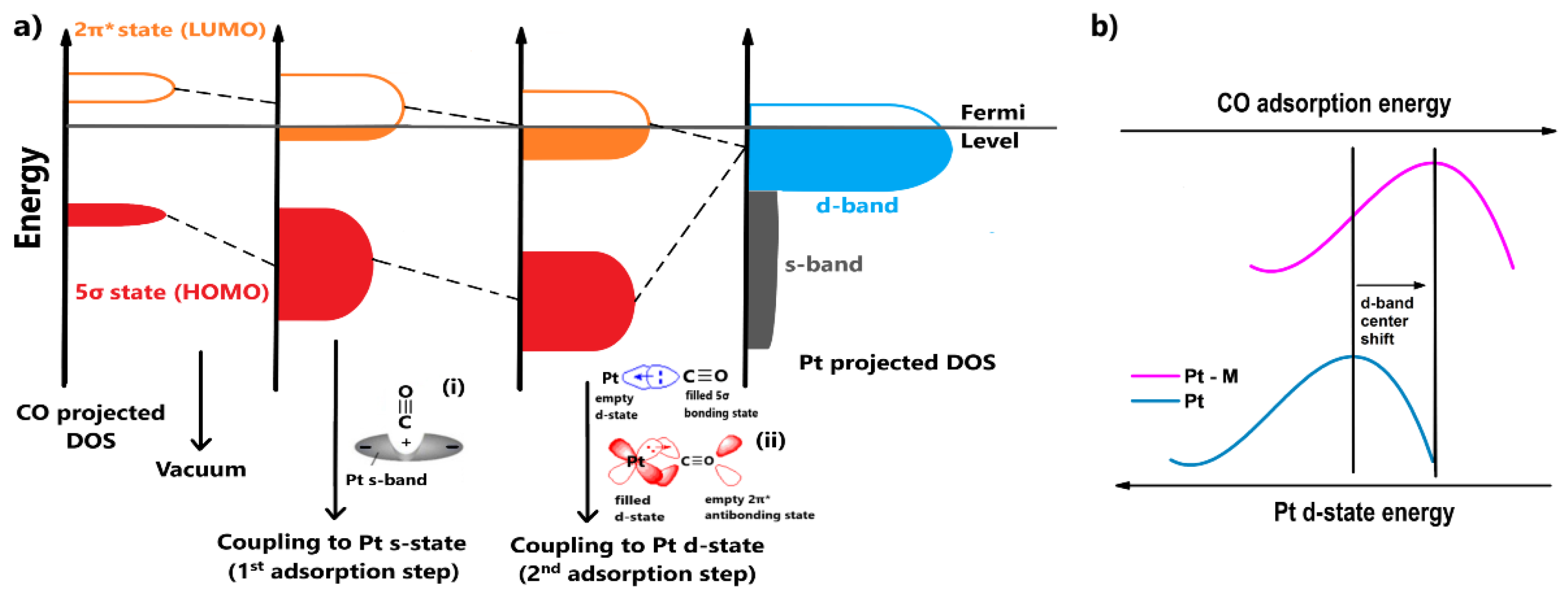
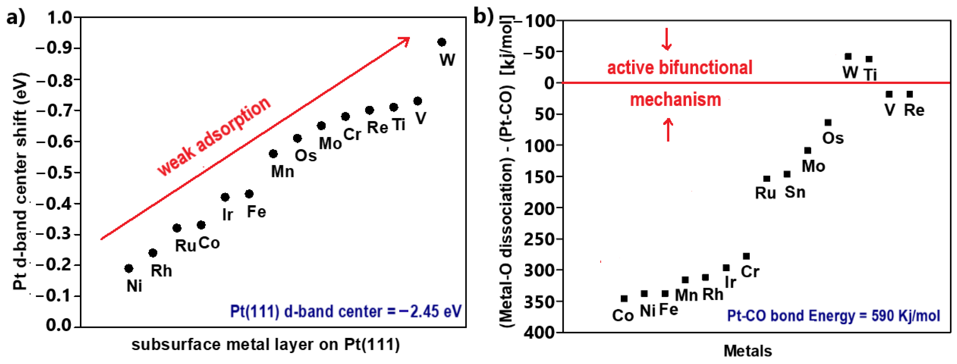
  • The adsorbate orbitals are hybridized with the s-state of Pt. This interaction results in the energy downshifting and broadening of both 2π* and 5σ CO states, as shown in Figure 2a. Schiros et al. [42] suggested that this type of hybridization positively polarizes the metal s-state due to an electron distribution (Figure 2a(i)); therefore, the orbital of the adsorbate is coordinated through an attractive electrostatic interaction, promoting to some extent the bond formation;
  • Two stabilization effects occur synergistically between the renormalized CO states and Pt d-state. Through this interaction, the respective bonding and antibonding states of 5σ and 2π* states are formed. The contribution of the 5σ antibonding state is considered minimal. First, an electron transfer arises from the highest occupied molecular orbital (HOMO) of CO, the filled 5σ bonding state, to the Pt d-state, increasing its electron density. To compensate for this effect, electrons are back-donated from the Pt d-state to the lowest occupied molecular orbital (LUMO) of CO, the empty 2π* antibonding state (Figure 2a(ii)); therefore, total charge stabilization between the interacted DOS is achieved, leading to the Pt-CO binding [43,44,45].
The contribution of the first adsorption step to the bond formation is essentially the same for all the transition metals because they present similar featureless and broad s-states; therefore, the CO binding strength on metal surfaces is determined by the coupling of the CO valence states with the metal d-states. Since the 5σ state is overwhelmingly occupied (negatively shifted relative to the Fermi level) when CO binds with transition metals, the binding strength specifically depends on the occupation of the 2π* antibonding state, which is initially empty. The more filled the 2π* antibonding state is (negatively shifted relative to the Fermi level), the weaker the bond, due to destabilized interactions between the CO and the metal. According to Figure 2a, it becomes apparent that the more occupied the metal d-band, the lower its energy relative to the Fermi level and the emptier the CO 2π* antibonding state during CO adsorption. Conclusively, the Pt-CO binding strength can be weakened by reducing the Pt d-band energy (or the d-band center) [43,44,45].
When Pt is combined with another metal, the energy of Pt’s d-state can be decreased via the hybridization of the d-states and a strain effect, such as lattice contraction–expansion or generation of surface defects. As explained previously, the decreased energy of Pt d-states leads to a more positive CO binding energy (CO binding weakens), meaning the CO desorption rate is facilitated. Consequently, the CO surface coverage is decreased and eventually the CO tolerance is improved [46,47]; this is the so-called electronic effect. In Figure 2b, the electronic effect is qualitatively illustrated with respect to the Pt d-band center, highlighting the energy of the Pt d-state [48].
It is noted that the electronic structure of a catalyst is in general related to its adsorption properties; therefore, a possible simultaneous strengthening of the catalyst-OH bond would additionally promote the bifunctional mechanism [47].
The two CO tolerance mechanisms can be concurrently responsible for CO tolerance improvement. Generally, the electronic effect predominates at low potentials (<0.2 V), where CO adsorption is favored, while the bifunctional effect is activated at higher potentials, where CO oxidation occurs [49]. The dominance of each mechanism depends on the electronic and physicochemical properties of the additive metal. Furthermore, the structure architecture, surface morphology, composition, and alloying degree of catalysts affect the function of CO tolerance mechanisms and the mitigation of CO poisoning [18,50,51].

2.3. Energetic View of CO Tolerance

A quantitative view of CO tolerance can be obtained by evaluating the energetic parameters of the materials relative to the reactants associated with CO poisoning in H2-PEMFC anodes. Commonly, the energetic descriptors of CO tolerance towards HOR are the adsorption energies of H2 (ΔEH), CO (ΔECO), and OH (ΔEOH) of catalysts [52,53,54]. Alternatively, the Gibbs free energy of adsorption can be used as an energetic descriptor with the same validity, as the two parameters are fundamentally related between them with the following thermodynamic equation [55]:
Δ G a d s = Δ H a d s T Δ S a d s < 0
Here, ΔGads is the Gibbs free energy of adsorption, ΔHads is the adsorption enthalpy, ΔSads is the adsorption entropy, and T is the temperature relative to the absolute value. Practically, the adsorption energy originates from the adsorption enthalpy. In the equation, the thermodynamic parameters are denoted as changes relative to the standard state. It is noted that for fuel cell reactions, the ΔGads and ΔHads are negative, as the related adsorption processes are spontaneous and exothermic. It becomes apparent that the more negative the adsorption energy, the stronger the adsorption.
When Pt is combined with another metal, an increment in ΔECO, corresponding to smaller CO coverage, is required for CO tolerance enhancement. Concurrently, the ΔEH is also expected to change, as is the H2 coverage, as the electronic modification of Pt by the additive metal generally influences the adsorption properties of the catalyst; therefore, an optimal correlation between ΔECO and ΔEH is required for both high HOR activity and CO tolerance achievement. Additionally, a stronger binding of OH (or oxygen) on catalysts, resulting in a more negative ΔEOH (or ΔEO), indicates acceleration of CO oxidation and shifting of CO oxidation at more negative potentials [47,56]. Conclusively, taking Pt as a reference, a positively shifted ΔECO of a modified catalyst indicates the introduction of the electronic effect, while a negatively shifted ΔEOH indicates an active bifunctional mechanism. Both mechanisms can be active in a CO-tolerant catalyst, although the dominance of each in terms of the overall CO tolerance can vary.
The adsorption energies of the molecules and atoms involved in the reactions for the electrocatalyst of interest are determined with the aid of quantum simulation models. The most widely applied computational method involves the density functional theory (DFT) calculations, through which the adsorption energies of the reactants are calculated on specific catalyst surface facets. Commonly, the selected facets for simulation are those where the reaction dominantly occurs, meaning that the results represent the activity of the catalyst as a whole. The simulation results of DFT calculations have been proven to satisfactorily agree with the experimental results [57,58,59]; therefore, the DFT calculations method can either be applied before the experimental procedure to predict the CO tolerance in advance or after to validate the energetic aspects and the dominance of each CO tolerance mechanism of an electrocatalyst.
Back et al. [60] used open-access DFT calculation databases relating to the H2 and CO adsorption on intermetallic crystals to propose promising cost-effective materials for the development of electrocatalysts with high HOR activity, CO tolerance, and stability in acidic media. The used DFT databases do not include information for all of the active sites of the materials. For credible simulation, the surfaces are modeled with all unique facets for each intermetallic crystal.
Based on the literature, the researchers argued that the DFT calculations correlate sufficiently with the experimental results when the Gibbs free energy of adsorption is used as an activity descriptor. Considering that the exploited DFT databases are available in terms of adsorption energies, they converted their final results into Gibbs free energies of adsorption by applying enthalpic and entropic corrections originated by Equation (14). For optimal HOR activity, they referred to the ΔGH = 0 eV, based on published results on the most efficient Pt(111) facet. For high CO tolerance, they took as a reference ΔGCO values that were more positive than they were vulnerable to poisoning Pt(111). Finally, the electrochemical stability was predicted via pH-potential (Pourbaix) diagrams. Pourbaix diagrams are designed through thermodynamic calculations; thus, the electrochemical stability can be evaluated in terms of eV/atom (ΔGPourbaix). When ΔGPourbaix tends to zero for pH = 0, the material can be considered stable in acidic environments (Figure 3).
Based on the abovementioned, their DFT calculations revealed eighteen promising materials, with four of them additionally being low in cost and stable. The best candidate was Cu3AsSe4, as it presented an optimum correlation between H2 and CO binding free energies, as well as suitable price and stability (Figure 3). In this work, the aim of energetics determination process is to predict a practical stable and CO-tolerant electrocatalyst for further experimental validation.
In contrast, Kwon et al. [61] applied DFT calculations to evaluate the experimentally proven enhanced CO tolerance of Pt-Ir/C compared to Pt/C in terms of electronic and thermodynamic aspects. The DFT model, based on (111) surface facets, confirmed that CO binding is weaker on Pt/Ir(111) than Pt(111), with ΔΕCO values of −1.63 and −1.89 eV, respectively. This result indicates that the addition of Ir to Pt enhances the CO tolerance through an electronic modification. Furthermore, OH was found to adsorb more strongly on Pt/Ir(111) than Pt(111), with ΔΕOH values of −1.91 and −1.67 eV, respectively, implying a higher CO oxidation rate through a bifunctional mechanism.
In conclusion, the knowledge of the energetic properties of materials can be a powerful tool for determining CO tolerance with respect to electronic properties and atomistic interactions. Furthermore, it can provide information about the function insights of CO tolerance mechanisms when Pt is combined with another metal; therefore, an in-depth understanding of the correlation between thermodynamics, electronic structures, and reaction kinetics is essential to evaluate the experimental results.

3. Overview of State-of-the-Art CO-Tolerant Electrocatalysts

Herein, we categorize the recent strategies for the development of CO-tolerant anode electrocatalysts for H2-PEMFCs and thoroughly discuss the most influential studies related to each strategy. The discussion aims to provide a fundamental understanding of the correlation between the physicochemical properties of the materials and the CO tolerance mechanisms and stability.

3.1. Pt-Based Electrocatalysts Supported on Carbon
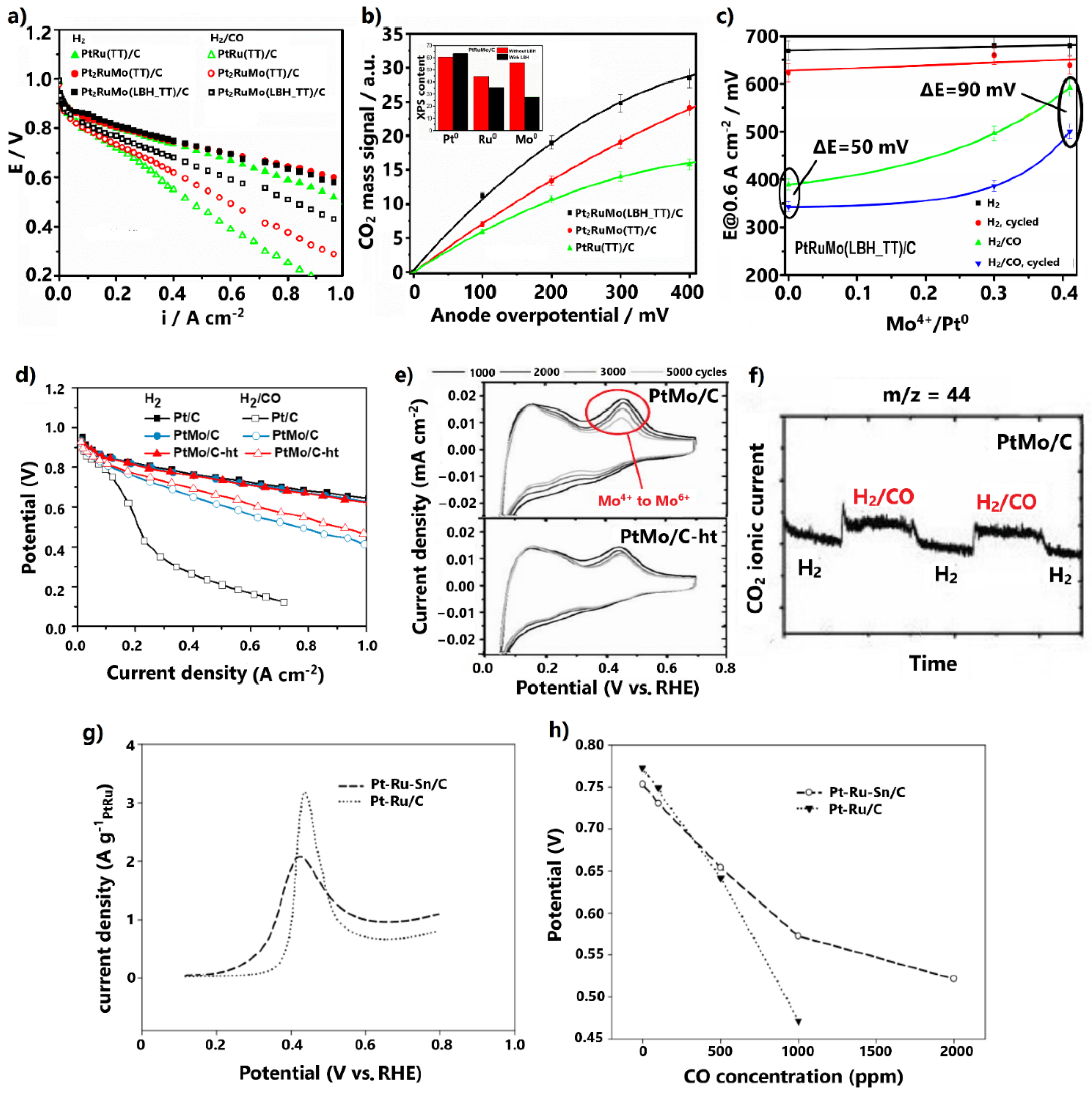
3.1.1. Alloys

Alloying Pt with other metals has been established as an effective strategy for enhancing CO tolerance. Generally, the synergism between the alloyed metals can improve the electrocatalytic activity by: (i) altering the active surface area; (ii) modifying the electronic properties, thereby changing the adsorption energies of the reaction intermediates; (iii) causing the strain effect, as well as influencing the adsorption properties; (iv) modifying the catalyst structure [62,63,64]. Regarding CO tolerance, alloying Pt with oxophilic metals activates the bifunctional mechanism, through which oxygenated species are formed on the surface of the added metal at lower potentials than those of Pt, resulting in accelerated CO oxidation [65]. Concurrently, considering that the adsorption energy of CO on the catalyst’s surface is defined by the coupling between the CO valence states and the metal d-states, the modification of the electronic properties of Pt induced by the added metal activates the electronic effect. The electronic effect results in a weakened Pt-CO bond and in decreased CO coverage on the catalyst surface. It is pointed out that concurrently the Pt-H bond strength should be optimal to ensure an efficient HOR [66,67].
Motivated by the abovementioned aspects, several Pt-M (M = Ru, Mo, Co, Sn, Pd, Au, Fe, Ni, W, Ir, etc.) alloys have been investigated for their CO tolerance in H2-PEMFCs anodes, with PtRu/C being established as the most feasible option [35,68,69]; however, conventional Pt alloys do not present commercialization prospects due to their sensitivity at relatively high CO concentrations and their poor stability.
Recently, new synthesis routes have been applied to upgrade both the CO tolerance and stability of conventional Pt alloys by adjusting their physicochemical properties. For example, Gonzalez-Hernandez et al. [70], for the development of a Pt-Ru-Mo ternary alloy, examined the impact of the presence of Li(C2H5)3BH (LBH) on the modified polyol synthesis method, followed by thermal treatment (TT) at 600 °C under H2 atmosphere. Polarization PEMFC curves for H2 and 100 ppm CO/H2 feed revealed that ternary PtRuMo/C, both in the presence and absence of LBH, presents milder CO poisoning effects than PtRu/C (Figure 4a). Interestingly, the presence of LBH was proven to increase further than the CO tolerance.
The increment was ascribed to physicochemical modifications introduced by LBH. XRD and XPS measurements showed that the alloying degree decreases in the presence of LBH; hence, the content of Mo4+ oxidation states on the catalyst surface correspondingly increases (Figure 4b, inset). Specifically, the enhanced CO tolerance was ascribed to an upgraded bifunctional mechanism and water–gas shift reaction, due to the higher contents of formed oxygenated species attributed to Mo4+ oxidation states. On-line mass spectroscopy measurements at the anode outlet revealed that the larger the content of Mo4+, the higher the oxidation rate of CO to CO2 (Figure 4b); however, metal-oxidized species are generally more vulnerable to dissolution in acidic environments than metallic components, due to their low redox potential [71,72]. This fact was demonstrated by comparing the cell potential at 0.6 A cm−2, before and after aging tests of 1000 cycles, for elevated Mo4+ contents (Figure 4c). It was confirmed that the higher the Mo4+ content on the catalyst surface, the lower the alloying degree and the lower the stability.
Hassan and co-workers [73] followed the opposite path, i.e., increasing the alloying degree of PtMo/C by including a heat treatment step (600 °C for 1 h under H2 atmosphere) in the formic acid reduction synthesis method. It was found that the heat-treated catalyst (denoted as PtMo/C-ht) presented both higher CO tolerance (Figure 4d) under 100 ppm CO poisoning and higher stability compared to the corresponding untreated catalyst. The stability was revealed via accelerated stress tests (AST) at 25 °C for various numbers of cycles (Figure 4e).
The decrease in the oxidation peak at 0.4 V, representing the change of the Mo+4 oxidation state to Mo+6, was stabilized after 1000 cycles for PtMo/C-ht, while for the respective untreated catalyst continuously declined. This behavior was associated with less Mo dissolution in the PtMo/C-ht and with improved stability.
The authors [73] attributed the improved CO tolerance and stability to the higher alloying degree induced by the heat treatment under H2 atmosphere. Previous studies have demonstrated that heat treatment under the forceful reducing H2 atmosphere causes sufficient reduction of metal salts, resulting in a high alloying degree and large ratio of metallic/oxide catalyst surface states [74]. Since the content of the easily leached Mo-oxidized species on the catalysts surface is reduced, the stability of the catalyst is improved. Additionally, the structure is well-ordered due to the efficient incorporation of Mo into the Pt lattice, as well as the stable and larger mean nanoparticle size arising from sintering during heat treatment, explaining the improved stability [71,74]. This result is in accordance with the findings of the former study, whereby stability degradation was reported for lower alloying degrees. Nevertheless, it is noted that even a small amount of leached Mo can be deposited at the cathode catalyst layer due to crossover, which can block its active surface area, leading to degradation of the overall PEMFC performance.
As a first approach, considering that Mo oxidation states have been established as a determining factor for the activation of the bifunctional mechanism, their smaller content on the catalyst surface due to the more sufficient alloying could indicate a suppression of CO tolerance [75,76]. This assumption is in opposition to the results of the discussed study (Figure 4d); however, there are supplementary factors that should be considered.
For example, it has been proven that Mo sites can activate water molecules for the direct conversion of CO to CO2 through the water–gas shift reaction [78]. This property of Mo was clearly disclosed by the authors via on-line mass spectroscopy, applied at the anode outlet of the cell at OCV, where the bifunctional mechanism is inactive (Figure 4f). When pure H2 was replaced with contaminated fuel containing 1000 ppm CO, an instant increment in the ionic current of CO2 was observed for PtMo/C, indicating the oxidation of CO to CO2. The higher alloying degree can provide more available Mo sites adjacent to Pt sites, thereby further promoting the water–gas shift reaction. The same applies to the bifunctional mechanism. Additionally, the higher alloying degree can decrease the Pt-Pt distance, resulting in downshifting of the Pt d-band center and weaker CO adsorption [74,79].
Similar redox properties with Mo have been reported for Ru and Sn, which have also been established as favorable additives for developing CO-tolerant Pt alloys [71,80]. Additionally, it has been demonstrated that the inclusion of a suitable third metal in the Pt-Ru alloy can further enhance the CO tolerance [81,82,83,84]. In this light, Takeguchi et al. [77] developed the ternary Pt-Ru-Sn/C via a rapid quenching synthesis method, including a quick heat treatment step in H2 at 880 °C for 15 min, in order to promote the formation of a trimetallic alloy structure. CO stripping voltammetry revealed that the addition of Sn to the Pt-Ru negatively shifts the onset and peak CO oxidation potentials by 60 and 20 mV, respectively (Figure 4g). The enhanced CO tolerance was confirmed by a single PEMFC test, whereby the cell voltage was measured at 0.2 A cm−2 for different CO concentrations in the hydrogen fuel (Figure 4h), ranging from 100 to 2000 ppm. For 100 ppm CO poisoning, Pt-Ru-Sn/C exhibited only 28 mV overpotential, while for CO concentrations higher than 500 ppm, it presented much higher tolerance than the PtRu/C anode.
The enhanced CO tolerance was exclusively attributed to a reinforced bifunctional mechanism arising from the propensity of Sn to nucleate OH species on its surface at low potentials. An electronic effect was rejected by the authors, because as stated the metallic Sn cannot introduce influential electronic modifications to Pt; however, previous studies do not agree on this point. It has been proposed that when Sn is alloyed with Pt, electron donation occurs from the Sn orbital to Pt orbital, leading to a downshift of the Pt d-band center and weakened CO adsorption [85,86]; therefore, an electronic effect should not be disregarded. It is also noted that in the absence of CO, Pt-Ru-Sn/C presented a lower cell potential than Pt-Ru/C and lower HOR activity (Figure 4h). This was ascribed to Pt-Sn alloying, which correspondingly decreases the degree of Pt-Ru alloying, resulting in suppression of HOR activity due to the tendency of Sn to adsorb H2O molecules weaker than Ru.
The latter study highlights how the inclusion of a third metal in Pt-Ru can further enhance the CO tolerance through the reinforcement of the CO tolerance mechanisms; however, since Ru and Sn are prone to dissolution in acidic environments, and also considering the conventional ternary alloy structure, we could not expect sufficient stability.

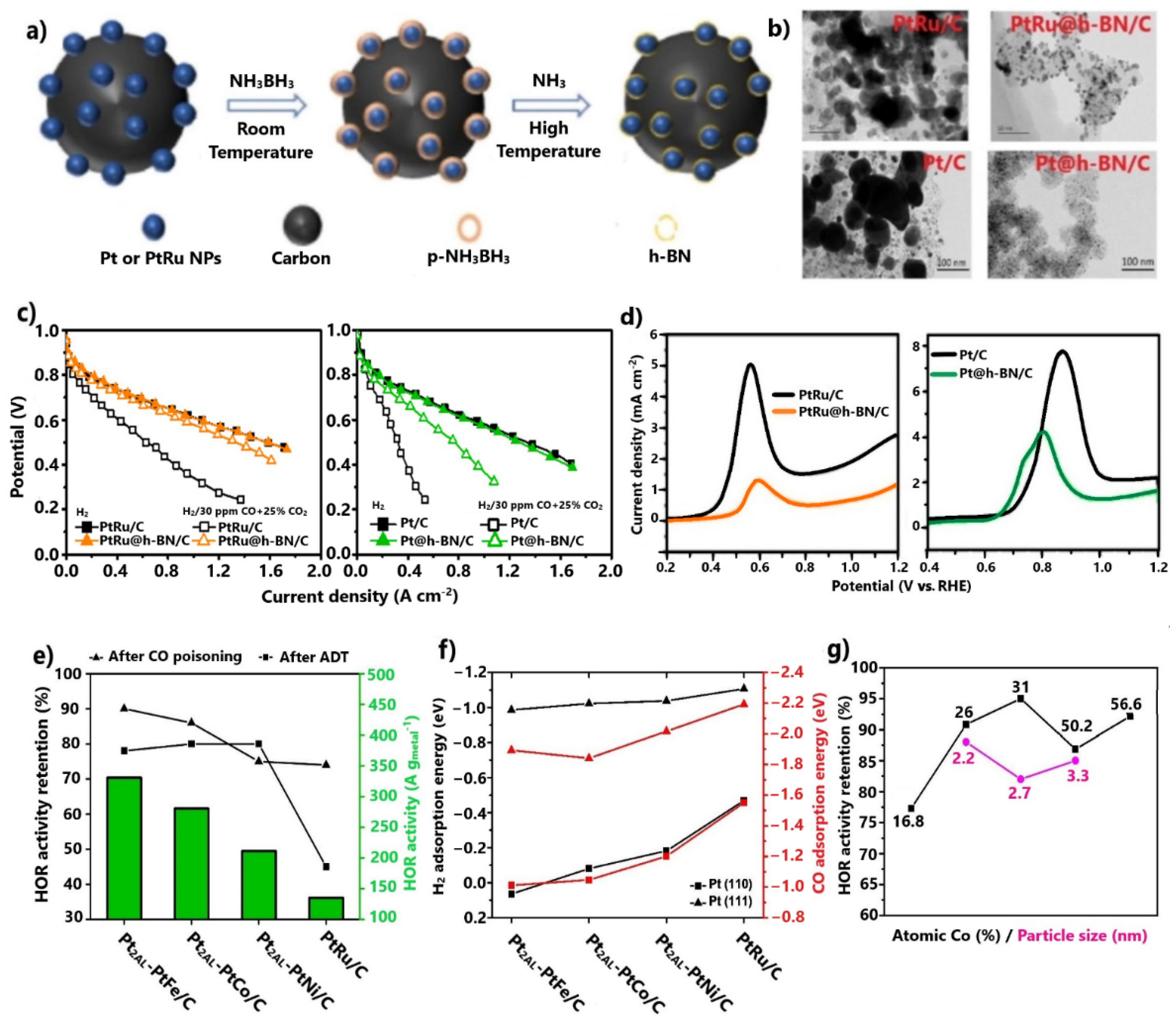
3.1.2. Core–Shell Structures

As we noted, Pt alloys are not yet suitable for practical PEMFC applications because of their thermodynamic and electrochemical instability [63,87]. An alternative approach to further improve the CO tolerance and simultaneously inhibit the disadvantages of Pt alloys is to design catalysts with advanced morphologies and structures. The morphologies and structures define the surface site densities, energy levels, and adsorption properties of electrocatalysts, and in turn their catalytic activity and stability levels; therefore, by tuning these features optimally via suitable synthesis routes, highly CO-tolerant and stable anode electrocatalysts can be obtained [88,89,90].
In this direction, the Ru@Pt core–shell-structured electrocatalyst has been widely explored over the last decade, demonstrating enhanced CO tolerance and stability compared to the Pt-Ru alloy. Its superior CO tolerance is attributed exclusively to the electronic effect, arising via the interaction between the Pt shell and the Ru core. A contribution of a bifunctional mechanism by Ru is rejected, as the encapsulation of Ru on the Pt shell deters the formation of hydroxyl species on its surface. Meanwhile, the lack of exposed Ru atoms on the surface of the electrocatalyst prevents their dissolution, resulting in a significant stability improvement. Additionally, the development of core–shell structures constitutes an effective way to reduce the Pt loading, and thus the total catalyst cost [91,92,93].
Research efforts to date on CO-tolerant core–shell-structured electrocatalysts have recently led to significant progress. Lee et al. [94] synthesized the ternary PtRuNi/C with a composition gradient shell via a high-temperature heat treatment method, combined with a polydopamine (PDA) protective coating technique (Figure 5a). Since high-temperature annealing is compulsory to achieve a core–shell structure, the formed PDA layer contributes to prevent sintering of metal nanoparticles (NPs) during heat treatment. Sintering leads to large metal NPs, small catalyst active surface areas, and consequently to low activity.
HR-TEM images showed (Figure 5a(i,ii)) that the PDA layer was removed after heat treatment, while concurrently the size of the metal NPs remained unchanged. The significance of including a PDA protective coating step in the synthesis method was highlighted by comparing the HR-TEM images of the same catalysts synthesized in the presence and absence of a PDA layer (Figure 5a(iii,iv)). In the latter case, the catalyst presented a larger mean metal NP size with several extensive agglomerates on its surface. The benefit of the developed ternary composition gradient shell structure in terms of CO tolerance was demonstrated in a single PEMFC, whereby PtRuNi/C exhibited significant enhanced properties compared to commercial PtRu/C, with only 11% activity decay at 0.6 V, due to 10 ppm CO poisoning (Figure 5b).
The negative shift of the binding energies of the Pt 4f XPS spectra of PtRuNi/C relative to Pt/C and PtRu/C indicates that the enhanced CO tolerance is due to an electronic effect, which is activated by electron donation from the consecutive Ni and Ru cores to the Pt shell (Figure 5c). Most importantly, the catalyst fully maintained its activity after 100 h of PEMFC operation at 0.5 V in the presence of 10 ppm CO (Figure 5b, inset). The excellent stability was correlated with the protection of the susceptible to dissolution Ni and Ru cores by the consecutive Ru and Pt shells, respectively.
We should note that despite the superior CO tolerance and stability, the complicated synthesis method implemented for the development of the ternary catalyst with the gradient composition shell may hinder its wide reproducibility for commercial purposes. Nevertheless, this approach has not yet been thoroughly investigated; thus, there is still room for further progress. Indicatively, simpler pathways for the development of core–shell structures could be explored, or metals that have demonstrated more intense electronic effects than Ru and Ni, such as Co and Fe, could be used.
Sun and co-workers [95,96] managed to enhance the CO tolerance of commercial PtRu/C and Pt/C by encapsulating them within multilayer graphitic hexagonal boron nitride (h-BN) 2D shells via an ammonia borane dehydrogenation process (Figure 6a). First, the 2D h-BN shells were found to protect the embedded metal cores from sintering during the heat-treatment synthesis step, providing high stability under oxidative atmospheres. This effect was disclosed by comparing the TEM images of the core–shell-structured electrocatalysts and the corresponding commercial ones after thermal treatment at 600 °C in H2 for 10 h (Figure 6b). Additionally, it has been proven that after long-term tests in acidic solution, h-BN cells offer exceptional electrochemical stability [97].
Regarding CO tolerance, the modified catalysts showed significant improvement in a PEMFC test for 30 ppm CO and 25 vol.% CO2 contamination (Figure 6c). PtRu@h-BN/C [95] exhibited minimal overpotentials due to poisoning. The enhanced CO tolerance was attributed to the 2D h-BN shells, which were considered to confine the CO adsorption on the surface of encapsulated electrocatalysts.
CO stripping voltammetry proved that in a complimentary manner to the slightly negatively shifted CO oxidation peak potentials, the CO oxidation charges of the core–shell-structured catalysts were significantly suppressed (Figure 6d). This fact indicates smaller CO coverage on the surfaces of the catalysts. Additionally, the identical PEMFC activities of the modified and commercial anodes in the absence of CO justified that the weak interactions between the 2D multilayer h-BN shells and the metal cores only impede CO and not H2 adsorption.
The benefits of 2D nanomaterials towards electrocatalysis have very recently been explored; therefore, since research developments are ongoing regarding this topic, we can expect significant progress for CO-tolerant core–shell-structured electrocatalysts in the future. Furthermore, 2D nanomaterial shells protect the embedded metal cores from dissolution; thus, PGM loading can be reduced, as the use of non-noble metals is not prohibitive in terms of stability [101]. Reducing the PGM loading is essential to decrease the overall PEMFC cost and to promote commercialization.
Shi et al. [98,99] investigated the CO tolerance of Pt alloys with non-noble metals (Fe, Co, Ni), which were additionally embedded on uniform and thin Pt skins of two atomic layers. The HOR activity results at 70 °C after 1000 ppm CO pre-adsorption revealed that all Pt2AL-PtM/C (M = Fe, Co, Ni) compounds exhibited much higher CO tolerance than PtRu/C (Figure 6e). Notably, Pt2AL-PtFe/C presented 90% HOR activity retention after contamination. It is noted that the same order of catalyst activity was observed for the HOR in the absence of CO. Moreover, after durability tests over 2500 cycles, it was verified that the novel catalysts exhibited considerable improvements in stability compared to PtRu/C (Figure 6e). The authors suggested that the non-noble metal core is protected from dissolution due to its encapsulation on the Pt skin.
The HOR activity results, in the presence and absence of CO, were rationalized with the aid of DFT calculations. It was proven that the adsorption energies of catalysts for the on-top CO and V configuration involving two H atoms was consistent with the trend revealed from the CO tolerance and HOR results, with Pt2AL-PtFe/C presenting the most positive values for all Pt skin step edges (Figure 6f); therefore, the CO tolerance enhancement was ascribed exclusively to the electronic modification of the Pt skin by the embedded alloy.
The same group evolved its research [100] by investigating the effects of the core–alloy composition and particle size of PtXAL-Pt100−xCox/C on CO tolerance. The optimum HOR activity results after 1000 ppm CO pre-adsorption were obtained for 31% atomic Co with a mean particle size of 2.2 nm (Figure 6g). Both catalysts presented equivalent or even higher CO tolerance relative to all Pt2AL-PtM/C (M = Fe, Co, Ni). Furthermore, their stability remained high. The enhanced CO tolerance was attributed to an upgraded electronic effect, resulting in even weaker CO binding on Pt skin sites; thus, the effects of the morphology and metal composition on CO tolerance should be considered in future studies.

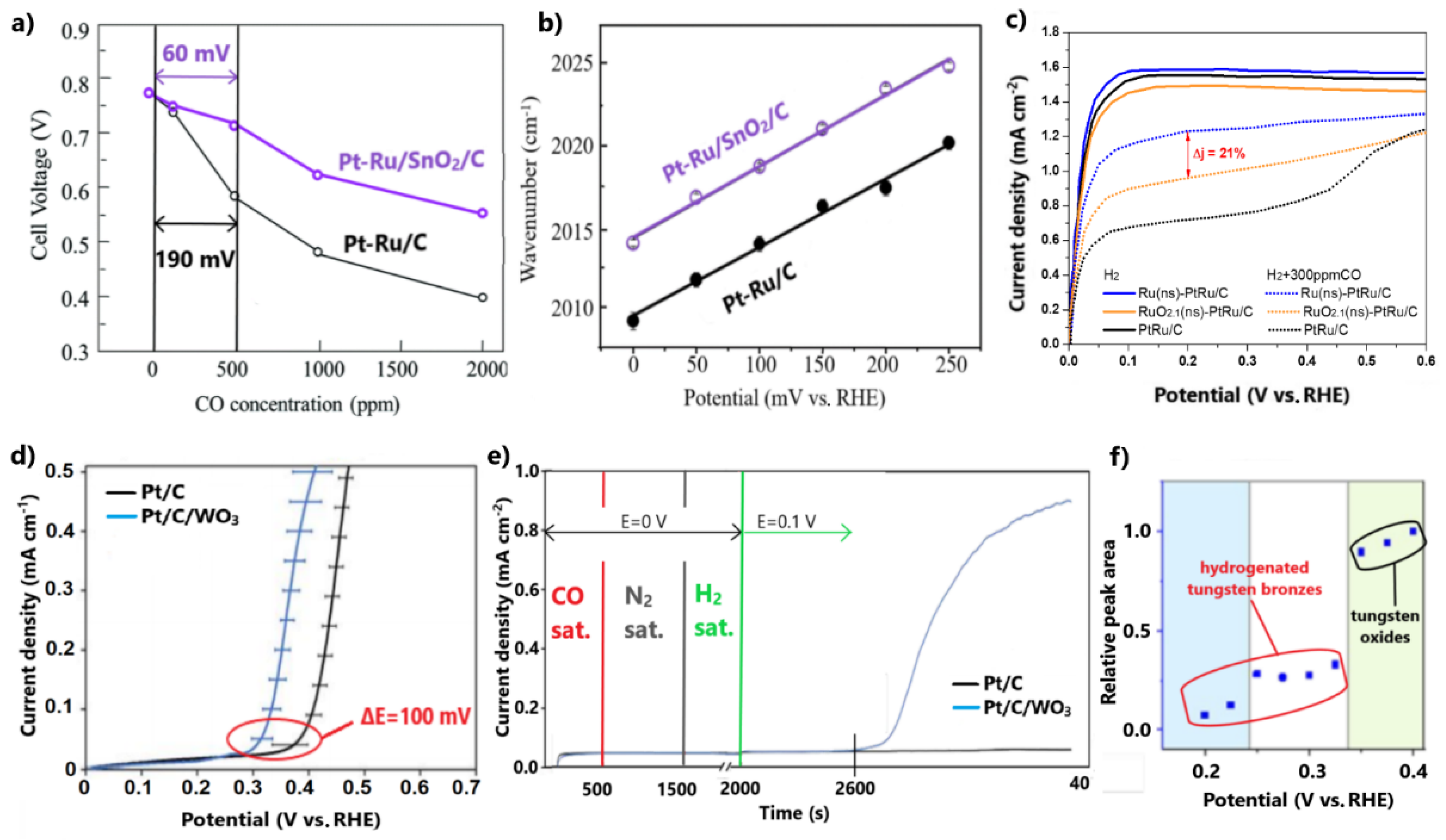
3.1.3. Combinations with Metal Oxides

Typically, metal oxides exhibit better thermodynamic stability and higher corrosion resistance in acidic environments than their corresponding metallic forms. Regarding CO tolerance, besides introducing the electronic effect, the abundant oxygen species on their surfaces can effectively promote the bifunctional mechanism [102,103]. As such, the combination of Pt with TMOs is still being investigated as an alternative approach for developing CO-tolerant anode electrocatalysts for H2-PEMFCs.
Takeguchi et al. [104] negatively shifted the onset and peak CO oxidation potentials of Pt-Ru/C by 150 and 70 mV, respectively, by modifying it with SnO2. The enhanced CO tolerance was demonstrated in a PEMFC test in the presence of different CO concentrations, ranging from 100 to 2000 ppm. Pt-Ru/SnO2/C exhibited higher cell potentials at 0.2 A cm−2 than Pt-Ru/C for CO concentration in H2 feed (Figure 7a). The influence of SnO2 on CO tolerance is highlighted for the case of 500 ppm CO, where Pt-Ru/SnO2/C presented an overpotential of only 60 mV due to poisoning, while the respective overpotential of Pt-Ru/C was 130 mV higher.
The authors argued that the inclusion of SnO2 in Pt-Ru boosts the bifunctional mechanism through the propensity of the metal oxide to form OH molecules on its surface sites. Furthermore, an electronic effect was observed with in situ surface-enhanced infrared absorption spectroscopy (SEIRAS) experiments after CO adsorption. The weakened CO binding on the surface of the novel catalyst was indicated by the positive shift of the peak CO-adsorbed wavenumber over the whole potential range between 0 and 250 mV (Figure 7b).
The same research group [77] demonstrated that the inclusion of SnO2 in Pt-Ru results in both higher CO tolerance and HOR activity than the inclusion of metallic Sn in a ternary alloy system. The discrepancy in CO tolerance was attributed to the presence of different valence states of Sn in each catalyst surface, arising from heat treatment at alternative atmospheres during the synthesis process. The valence state in Pt-Ru/SnO2/C treated in He was four, while that in Pt-Ru-Sn/C treated in H2 was zero. The Sn in the valance state of four was correlated with attenuated CO adsorption and strengthened H2O adsorption, indicating both a pronounced electronic effect and bifunctional mechanism, respectively. Based on the stronger H2O adsorption, it was also assumed that the H2 adsorption was altered, justifying the improved HOR activity of Pt-Ru/SnO2/C.
Although it was not stated by the authors, we should present our suspicion that the discrepancy in CO tolerances may additionally be due to the different structures of the catalysts. Heat treatment in an inert atmosphere represses the formation of an alloy structure and favors the presence of metal oxide species on the catalyst surface, in contrast to heat treatment in the strong reducing atmosphere of H2; thus, it could be assumed that in Pt-Ru/SnO2/C, the active sites of the Pt-Ru alloy are unaffected [79]. Consequently, we can claim that the bifunctional mechanism due to Ru is not inhibited, while electronic and bifunctional effects are additionally introduced by SnO2. In contrast, when Sn is mixed with Pt-Ru in a ternary alloy structure, Pt-Ru sites may be partially restricted, suppressing to some extent the bifunctional mechanism through Ru. This behavior could explain the worse CO tolerance of Pt-Ru-Sn/C than Pt-Ru/SnO2/C.
Takimoto et al. [105] modified PtRu/C with metallic Ru nanosheets derived after hydrogen reduction of the corresponding RuO2.1 nanosheet-modified catalyst at 200 °C. Firstly, both modified electrocatalysts exhibited appreciably improved CO tolerance for 300 ppm CO poisoning compared to PtRu/C (Figure 7c).
As a first approach, the CO tolerance enhancement was attributed to the reinforcement of the bifunctional mechanism due to the incorporation of the Ru and RuO2.1 nanosheets. Based on the similar HOR activities of both modified catalysts in the absence of CO, it was concluded that the inclusion of nanosheets does not obstruct the Pt-Ru alloy structure, meaning the enhanced CO tolerance can also be ascribed to suppression of CO adsorption.
Comparing the two modified catalysts, Ru(ns)-PtRu/C presented 21% higher HOR current density values than RuO2.1(ns)-PtRu/C at 200 mV in the presence of 300 ppm CO (Figure 7c). Considering that CO oxidation initiates at potentials above 200 mV, the higher CO tolerance of Ru(ns)-PtRu/C was due to a more effective suppression of CO adsorption, attributed to a more intimate contact of metallic Ru nanosheets with the PtRu NPs. Moreover, it was proven that the more intimate contact of nanosheets with the Pt-Ru alloy reduces the dissolution degree of Ru. ADT for 3000 cycles showed that Ru(ns)-PtRu/C retains 10% more of its initial activity relative to RuO2.1(ns)-PtRu/C.
This discussion has so far demonstrated that the structure of catalysts plays a key role in the optimal exploitation of metal oxides in achieving high CO tolerance and stability. Stewart and co-workers [106] proposed a physical mixture catalytic system of commercial Pt/C and synthesized WO3 as a cost-effective development approach for a CO-tolerant anode electrocatalyst. The subtraction of the CO stripping voltammograms conducted in N2- and H2-saturated solutions, respectively, showed that the addition of WO3 negatively shifts the onset CO oxidation potential by ca. 100 mV (Figure 7d). This method excludes the overlapping oxidation of tungsten oxide to tungsten bronze. Additionally, a chronoamperometry test reflected the slow oxidation of CO even at the low potential of 0.1 V for Pt/C/WO3 (Figure 7e). It is noted that this property could not be determined by cyclic voltammetry due to the slow kinetics of CO oxidation at such low potentials.
Based on the fact that the physical mixture causes minimal electronic modifications, the enhanced CO tolerance was exclusively ascribed to a bifunctional mechanism induced by WO3. In situ Raman spectroscopy proved that the predominant CO oxidation step at potentials lower than 0.1 V is due to the presence of tungsten bronze, while the dominant step at potentials higher than 0.3 V is attributed to the hydroxyl species formed on WO3, derived from the reduction of the preformed tungsten bronze (Figure 7f). As such, in this study, CO tolerance was achieved close to the practical operational potentials of H2-PEMFCs by taking advantage of the redox properties of a metal oxide, without the need to develop a sophisticated catalyst structure through a complicated synthesis method; however, in light of the established dissolution issues of tungsten in acidic environments and the exposed WO3 on the catalyst surface, we must note our reservations regarding the adequate stability.
In general, recently published studies have highlighted the beneficial effects of combining metal oxides with Pt in terms of CO tolerance and the further progress that can be achieved by developing the appropriate structures; however, the novel CO-tolerant electrocatalysts need to be further investigated in regard to their stability.

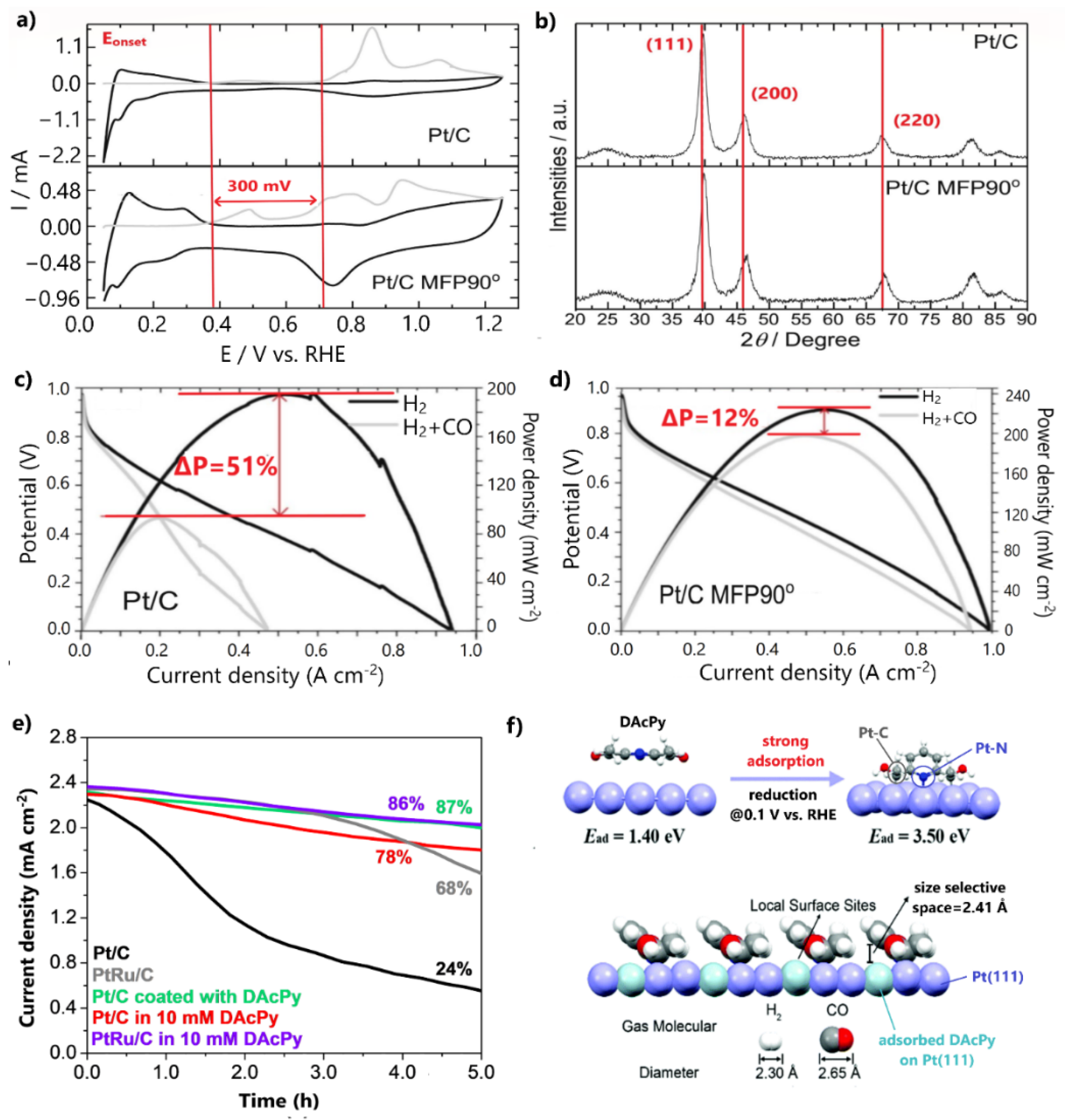
3.1.4. Surface-Modified Pt/C

By exploiting the surface-sensitive nature of the CO electrooxidation reaction, enhancement of the CO tolerance of the Pt/C anode can be achieved after appropriately modifying its conventional morphology and structure. Ciapina et al. [107] highlighted the effects of the type and size of the crystallographic planes as well as the size and distribution of NPs on CO oxidation. For example, they demonstrated that by synthesizing a Pt electrocatalyst with exposed (100) facets on its surface, the CO tolerance can be improved. The explanation lies in the propensity of hydroxyl species to form on Pt(110) facets rather than on Pt(111) and Pt(100). Proportionally, CO adsorption is preferential on Pt (110) facets; therefore, considering that CO oxidation follows the Langmuir–Hinshelwood mechanism (reaction involving two different species, see Equation (10)), the accumulation of the reactants at a specific facet facilitates the reaction; therefore, the CO tolerance is enhanced. The dominance of Pt(110) on OH formation and CO adsorption could be fundamentally based on the fact that crystallographic facets exhibit different surface energies. The higher the surface energy of a facet, the smaller its thermodynamic stability; consequently, the more preferred the adsorption (or dissociation) of the reactants on the facet, then correspondingly the higher its catalytic activity [108].
Recently, Ramos et al. [109] restricted the CO poisoning of Pt/C by adjusting its conventional surface and structural properties via a novel synthesis approach. This approach involved the reduction of a Pt precursor with sodium borohydride under the assistance of a 90° pulse magnetic field in a time-domain nuclear magnetic resonance spectrometer (TD-NMR). In a CO stripping experiment, Pt/C (denoted as Pt/C MFP90°) presented multiple CO oxidation peaks over a broad potential range, with oxidation initiation being 300 mV more negative than for the commercial Pt/C (Figure 8a). The recurring release of Pt/C MFP90° active sites from the adsorbed CO at lower potentials than for the respective commercial catalyst was ascribed to the surface defects and terrace adlayers introduced by the synthesis procedure, which promote the OH formation and CO oxidation.
Furthermore, XRD patterns revealed that Pt facet peaks of Pt/C MFP90° were positively shifted, indicating a compression of the lattice strain of the Pt crystalline structure (Figure 8b). This result was correlated with the negative shift of the Pt d-band center and with weakened CO adsorption; therefore, the early initiation of CO oxidation was due to an electronic effect, while the CO oxidation at higher potentials was due to a bifunctional mechanism. To reveal the improved CO tolerance, a PEMFC fed with 100 ppm CO/H2 was employed, in which a maximum power density decrease of only 12% was observed after the CO poisoning (Figure 8c).
A noteworthy approach was reported by Wang et al. [110], who chemically modified Pt/C by engineering an organic molecular architecture on its surface. Particularly, they coated 2,6-diacetylpridine (DAcPy), a pyridine derivative with two carbonyl groups, on the Pt/C surface and examined its stability for 100 ppm CO poisoning via a chronoamperometry test at 0.1 V. After 5 h of continuous contamination, the modified catalyst retained 87% of its initial current density, while the commercial Pt/C retained only 24% (Figure 8d). Notably, the CO tolerance of the Pt/C coated with DAcPy was even higher than that of commercial PtRu/C. A corresponding CO tolerance was observed for Pt/C and PtRu/C electrocatalysts tested in solutions containing 10 mM DAcPy; however, this approach was not recommended for PEMFC anodes due to the eventual detachment of the organic additive from the produced water.
The authors argued that when DAcPy is reduced, it is strongly adsorbed on the Pt surface, forming pyridine rings that act as a canopy. DFT calculations showed that the narrow space between the pyridine rings and Pt atoms inhibits the adsorption of the large CO molecules on catalyst sites below the pyridine ring, while concurrently permitting the adsorption of the smaller H2 molecules (Figure 8e); therefore, the high HOR activity of Pt is retained and CO poisoning is simultaneously prevented. Conclusively, CO tolerance is based solely on hindering CO adsorption and not on CO oxidation at all. This approach is extremely promising, as in an optimal situation a complete mitigation of CO poisoning could be achieved.

3.2. Pt-Based Electrocatalysts Supported on Alternative Materials

Depositing metal NPs on supporting materials has been acknowledged as an efficient strategy to improve the activity and durability of bulk metal electrocatalysts. The narrow distribution and homogenous dispersion of the metal NPs onto the support lead to a large electrocatalyst active surface area and to high catalytic activity with a small metal loading requirement. Furthermore, supporting materials with high electronic conductivity contribute to the reduction of the electrical resistance, facilitating electron transfer and reaction kinetics. Decreasing electrical resistance is vital in fuel cell applications, as most of the total polarization loss is ascribed to ohmic limitations [111,112].
Carbon black is the most widespread catalyst support, as it adequately satisfies the above requirements, including having low cost and wide availability; however, its surface is prone to electrochemical oxidation at the high operating potentials of PEMFCs. The oxidation of support causes corrosion, which is associated with the dissolution of metal from the catalyst layers and the agglomeration of metal NPs during operation, leading to catalytic instability [111,112]. As such, alternative nanomaterials have been explored to substitute carbon black supports. Among them, two types of materials have been distinguished: (i) advanced carbonaceous materials with modified structures, such as carbon nanofibers (CNFs), carbon nanotubes (CNTs), multiwalled carbon nanotubes (MWCNTs), and graphene; (ii) TMOs and TMCs. Both types were found to further increase the catalytic activity through their larger surface area and more mesoporous structure compared to carbon black. Concurrently, their electrical conductivity is usually more than adequate [113].
Focusing on the subject of the current study, we highlight the contribution of the above materials to CO tolerance. More insights are revealed in the following discussion regarding the most promising CO-tolerant, Pt-based electrocatalysts supported on alternative materials.

3.2.1. Advanced Carbonaceous Supports

Besides the corrosion issues related to carbon black, its relatively microporous and dense structure impedes the accessibility of the reactants to the metal NPs, reducing the catalytic activity and stability [111,112]. Recently, Narischat et al. [114] investigated the effects of carbon support structures on CO tolerance. For this purpose, PtRu NPs supported on resorcinol formaldehyde carbon gels (RFC) of different porosity densities were tested in a single PEMFC poisoned with various CO concentrations, ranging from 100 to 2000 ppm. The porosity of the supports was controlled by varying the resorcinol-to-catalyst molar ratio (RC = 200, 800, and 1000 mol/mol) during the preparation. N2 adsorption isotherms showed that the larger the molar ratio, the more mesoporous the carbon structure.
Substituting the conventional carbon support with carbons containing larger mesoporous volumes, i.e., RC1000 and RC800, led to significant enhancements in CO tolerance. PtRu/RC1000 exhibited 67% and 63% smaller overpotentials at 0.2 A cm−2 than PtRu/C for 500 and 2000 ppm CO poisoning, respectively (Figure 9a). Notably, the catalyst supported on RC200, containing the smallest mesoporous volume, was completely deactivated in the presence of only 100 ppm CO. The authors showed that the diffusion rate is proportional to the mesoporous volume of carbon and inversely proportional to CO poisoning, as proven by the PEMFC results for 500 ppm CO contamination (Figure 9b). Based on this, they concluded that water and CO easily diffuse on the sites of electrocatalysts with carbon supports containing the largest mesoporous volume and modal mesopore diameter; therefore, the water–gas shift reaction (CO + H2O ⇌ CO2 + H2) rate increases, decreasing the CO concentration and improving the CO tolerance. We additionally argue that the facilitated diffusion on PtRu anodes supported on RC1000 and RC800 can also be presumed from the higher PEMFC performance observed in the absence of CO, indicating higher HOR activity through more facilitated H2 mass transfer (Figure 9a). It is noted that the mesoporous volume decreased after the deposition of the metal NPs on the supports and the mixing of the catalytic samples with Nafion to fabricate the membrane electrode assemblies (MEAs). In Figure 9b, the mesoporous volumes and the diffusion rates calculated via the Knudsen equation using the modal mesopore diameters correspond to the catalytic samples after mixing with Nafion.
Another factor determining the effectiveness of catalyst–supports is the functionality of their surfaces. Carbonaceous materials have relatively inert surfaces [115]; therefore, surface functionalization is required to achieve high dispersion of metal NPs and effective catalyst–support interaction. The functionality can be accomplished via surface doping, as this introduces defects into the carbon lattice, leading to strong interactions between the catalyst and support [116,117]. The efficient stabilization of metal NPs onto the support alters the electronic interplay between the valance states of the support and the deposited metal, resulting in weaker CO binding and higher stability. Furthermore, specific doping elements such as boron can enhance the CO tolerance via the bifunctional mechanism, because of their ability to adsorb oxygenated species [118,119].
Gonzalez-Hernandez et al. [120] examined N-doped graphene nanoplatelets (N-GNPs) as alternative supports for PtRu and PtRuMo CO-tolerant anodes. Both catalysts supported on N-GNP exhibited higher CO tolerance than PtRu/C in a single PEMFC fed with 100 ppm CO-contaminated H2 (Figure 9c).
The authors suggested that the Pt-N bonds facilitate the formation and subsequent dissociation of oxygenated species on the catalyst surface; thus, CO oxidation is facilitated through the bifunctional mechanism. In their next study [122], where catalysts supported on N-doped and undoped GNPs were compared, they also presumed that strong binding between Pt and N causes an energy decrease in the d-state of Pt, resulting in a weakened CO adsorption. Furthermore, N-GNP supported anodes presented higher stability than PtRu/C after aging tests for 5000 cycles (Figure 9d). The presence of defects introduced by N-doping was considered to sufficiently stabilize the metal NPs on the support. The higher stability was demonstrated by TEM, whereby the N-GNP-supported catalysts showed a minimal particle size increase after the aging test, contrary to PtRu/C (Figure 9e).
The PtRuMo/N-GNP exhibited lower CO tolerance than PtRu/N-GNP (Figure 9c), while the same research group in a former study [70] stated the opposite for the same catalysts supported on carbon black. This fact was ascribed to a reduced amount of Mo+4 states on the surface of PtRuMo/N-GNP, indicating a weaker bifunctional mechanism. Seizing this opportunity, we highlight the strategies used for developing efficient materials for H2-PEMFCs anodes, which should guarantee (i) high CO tolerance, (ii) high HOR activity, and (iii) high stability. For this reason, an in-depth understanding of the correlation between the CO tolerance mechanisms and physicochemical properties of materials is required.
The surfaces of carbon supports can be alternatively functionalized by chemical pre-treatment. In this case, the CO tolerance is mainly attributed to the bifunctional mechanism. Escudero-Cid et al. [121] functionalized MWCNTs in a sulfuric–nitric mixture to support a Pt catalyst. The Pt/MWCNT anode showed a decrease in maximum power density of only 19% after 3.5 h of exposure to 10 ppm CO, whereas the Pt–Vulcan exhibited a loss of 63% (Figure 9f). FTIR spectra showed that several carbonyl, alcohol, and phenol compounds were present on the surface of MWCNTs due to OH species anchoring after functionalization (Figure 9g). These oxygenated groups, which facilitate the oxidation of CO to CO2 on the sites of Pt NPs, explain the significant improvement in CO tolerance after substituting Vulcan carbon with MWCNTs; however, the mean particle size of Pt NPs supported on MWCNTs was 2-fold larger than those supported on Vulcan carbon, resulting in lower maximum power density in the absence of CO due to a less active HOR (Figure 9f). This side effect is common for metal NPs supported on advanced carbons.

3.2.2. Transition Metal Oxides and Carbides

The high electrochemical and thermochemical stability of TMOs and carbides prevent their corrosion in acidic environments. In particular, the oxides and carbides of Mo, Ti, W, and their combinations have been confirmed to optimally meet these requirements, in addition to presenting adequate electronic conductivity. As such, these materials are endeared as alternative supports for H2-PEMFC electrocatalysts [123,124]. Regarding CO tolerance, water is dissociated on the active sites of these metals, forming hydroxyl species, through which the CO oxidation is promoted. Concurrently, the strong metal–support interaction causes electronic modifications in the supported catalysts, resulting in CO adsorption suppression [125,126].
We have seen [70,73,106,127] that the inclusion of Mo and W enhances the CO tolerance through the bifunctional mechanism, which is ascribed to their redox properties. In this manner, Mo and W oxide and carbide composites have recently been explored as supports for CO-tolerant electrocatalysts. The aim is to mitigate the CO poisoning and to avoid the use of carbon black, which is vulnerable to corrosion.
Brkovic et al. [128] significantly improved the CO tolerance of the PtRu anode by replacing the carbon support with non-stoichiometric tungsten carbide–oxide (WxCyOz). For the CO-contaminated H2 stream, the PtRu/WxCyOz exhibited a loss of 18% in maximum power density due to CO poisoning, while PtRu/C showed a loss of 32% (Figure 10a). Using a rotating disk electrode (RDE) test in a 2 vol.% CO/H2-saturated solution, it was revealed that WxCyOz contributes to the initiation of CO oxidation at potentials smaller than 0.3 V (Figure 10b). The CO oxidation at such low potentials was correlated with the formation of hydrogen bronze on the surface of the tungsten oxide–carbide support. Through this process, oxygenated species are donated to the conjoint metal NPs, promoting the bifunctional mechanism; however, in the absence of CO, the maximum power density of PtRu/WxCyOz is 7% lower than that of PtRu/C, probably due to the lower conductivity of the tungsten oxide–carbide support. Furthermore, although no information about the stability is provided, we express our skepticism based on the easy dissolution of Ru and W in acidic environments.
Vass et al. [130] achieved exceptional HOR activity under CO poisoning conditions by depositing Pt on the TixMo1−xO2-C composite. The method applied to examine the CO tolerance at low potentials is worth mentioning. Briefly, CO and subsequent H2 adsorption on catalyst sites were followed by electrode polarization at 250 mV in H2-saturated solution. Eventually, HOR linear sweep voltammetry (LSV) measurements were conducted. The same experiment was performed for 350, 450, 550, and 1000 mV electrode polarization potentials (Figure 10c(i–v)). Pt/Ti0.6Mo0.4O2-C achieved significant HOR activity after only 250 mV electrode polarization, while Pt/C and PtRu/C were fully poisoned. Notably, Pt/Ti0.6Mo0.4O2-C exhibited 70% of its HOR activity in the absence of CO. A similar activity order for catalysts was presented for electrode polarization at 350 mV.
The CO oxidation at such low potentials was attributed to some extent to the electronic modification of Pt, through its strong interaction with the transition metal oxide–carbide support, and mainly to the bifunctional mechanism provoked by the redox properties of Mo oxides.
Specifically, Mo in oxidation states lower than 6+ at potentials smaller than 250 mV dissociates water molecules to form MoO(OH)2 species, which in turn promote the oxidation of the weakly adsorbed CO on the adjacent Pt sites. At higher potentials, the Mo active species are oxidized into the less active Mo6+, meaning the CO oxidation is mainly ascribed to Pt. The shift of CO oxidation to the potential range where the HOR occurs in practical H2-PEMFC applications (<250 mV) highlights the prospect of using the TixMox−1O2-C composite as an alternative support for CO-tolerant anode electrodes; however, some issues must be addressed to allow practical utilization.
In the absence of CO (Figure 10c(v)), Pt/Ti0.6Mo0.4O2-C exhibited 20% and 30% lower HOR activity levels than Pt/C and PtRu/C, respectively (Figure 10c), due to the lower conductivity of TixMox−1O2-C than carbon. Furthermore, as the same research group showed in their subsequent study [129], TixMox−1O2-C is unstable in acidic environments. The stability was examined by comparing the HOR activity levels after CO poisoning with the previous method, before and after aging tests of 500 cycles, observing considerable degradation rates (Figure 10d). It was noted that the instability was more intense for the HOR activities taken after the polarization of electrode at low practical potentials. During the first 10 cycles, XPS measurements (Figure 10e) revealed a significant reduction of Mo6+ to lower oxidation states, indicating the leaching and redistribution of the Mo species that were not incorporated into the TiO2 lattice. During the next cycles and until the completion of the stability test, the oxidation states were relatively unaffected, as the incorporated Mo species were relatively stable; thus, a preparation method that can allow optimal incorporation of Mo species into the TiO2 lattice would lead to a both CO-tolerant and stable anode.
Finally, the approach of modifying metal oxide supports with polymers is worth mentioning. Liu et al. [131] supported Pt NPs on hexagonal tungsten oxide modified with polyethyleneimine (PEI). The aim of the modification with PEI was to positively charge the support, so that when combined with the negatively charged Pt colloid this would uniformly disperse the small (<3 μm) Pt NPs via an electrostatic interaction.
Although Pt/PEI-hex-WO3 exhibited similar CO oxidation potential levels to commercial Pt/C, its CO charge was 14-fold smaller (Figure 10f), implying considerably smaller CO coverage. The suppression of the CO charge was attributed to an electron donation from the support to Pt due to a strong metal–support interaction. Additionally, a shoulder CO oxidation peak at lower potentials (ca. 0.25 V vs. RHE) was observed, which was attributed to the promotion of CO oxidation via the formed hydroxyl molecules on the WO3 surface.

4. Outlook

In this paper, we have summarized and critically discussed the results presented in studies published over the last decade to gain a broader view of the progress made so far and to distinguish the most promising state-of-the-art CO-tolerant anode electrocatalysts.
Figure 11 summarizes the CO stripping voltammetry results for the Pt-based electrocatalysts investigated over the last decade in three-electrode electrochemical cell systems in acidic media.
Commercial Pt/C and PtRu/C [132] are additionally presented as benchmarks. For comparison reasons, only the values of the main CO oxidation peaks were considered, although less pronounced oxidation peaks, which may precede the main peaks, usually indicate a contribution to CO poisoning mitigation [133]. Furthermore, to ensure objectivity of the comparison, the catalysts tested at 60–70 °C are highlighted because the standard free energy of CO adsorption on catalyst sites decreases at elevated temperatures, resulting in milder CO poisoning [134]. Finally, we note that CO oxidation is accelerated to some extent in HClO4 solution compared to H2SO4 and at higher scan rates [135]. Although their influence is not considered significant for our discussion, for validity reasons, both the experimental conditions and electrocatalysts corresponding to the data in Figure 11 are listed in Table 1.
The results are presented relative to the onset potential and peak (CO oxidation) potential values. We chose to evaluate the results in terms of CO oxidation potentials because the peak oxidation current strongly depends on the experimental conditions, making it difficult to draw a valid comparison. At the onset potential, the CO adsorbed on the catalyst surface starts to oxidize, providing free active sites for occupation by hydrogen molecules and subsequent initiation of the HOR; therefore, the onset potential indicates the minimum potential in which HOR can be activated. At the peak potential, the rate of CO oxidation reaches a maximum value; therefore, even the strongest bonded CO molecules are oxidized. At higher potential values, the current starts to decline until the overall consumption of the absorbed CO occurs [151]. As such, the peak potential indicates the potential at which the overall HOR activity can be achieved. It becomes obvious that the more negative the onset and peak potentials, the faster the CO oxidation kinetics and the more CO-tolerant the electrocatalyst.
Although the results of CO stripping voltammetry tests offer a general view of an electrocatalyst’s CO tolerance, they cannot predict the behavior of an electrode in a H2-PEMFC anode. CO stripping is conducted in an inert environment to allow the oxidation of pre-absorbed CO within a potential range of ca. 1 V. In contrast, in a PEMFC, a mixture of H2/CO gas is supplied at the anode, where H2 competes with CO for oxidation within a potential range of 0.2 V. For example, Pt/C MFP90° (datum 14 in Figure 11a) shows a 100 mV lower onset potential and a 150 mV higher peak potential than PtRu/C. Since the CO oxidation is not initiated or completed with the potential range in which HOR occurs in H2-PEMFCs for either electrocatalysts, we cannot reach a decision; a PEMFC test is required for this purpose. Nevertheless, the higher CO tolerance of Pt/C MFP90° than Pt/C is apparent; therefore, herein we analyzed the CO stripping voltammetry results to gain a fundamental outlook on the materials and methods that are favorable for improving the CO tolerance of Pt/C.
The electrocatalysts in Figure 11 can be grouped into two regions: region (i) encompasses the electrocatalysts that present higher CO tolerance than PtRu/C; region (ii) includes the electrocatalysts that exhibit negatively shifted CO oxidation potentials relative to Pt/C. At first glance, it is obvious that the CO oxidation potentials of most novel electrocatalysts are significantly shifted at more negative potentials than Pt/C; therefore, their higher CO tolerance is directly apparent. Even the electrocatalysts presenting CO oxidation potentials close to those of Pt/C [96,106,131,136,138,140,150] indirectly demonstrate enhanced CO tolerance. For example, Pt/TiO2NCs-C [150] presents a less intense preceding CO oxidation peak, while Pt/PEI-hex-WO3 [131] shows a negligible CO oxidation charge, indicating very weak CO adsorption.
In conclusion, we can argue that at this stage, the research goes far beyond improving the CO tolerance of the most commonly used Pt/C anode. Our statement is further confirmed by the fact that most of the electrocatalysts developed over the last decade have shown CO oxidation potentials close to those of PtRu/C, which is a well-established CO-tolerant catalyst; however, even at those potentials, CO oxidation still deviates significantly from the range of potentials in which HOR occurs in practical H2-PEMFC applications (ca. 0.1 V). The question that arises of whether the CO oxidation of an anode electrocatalyst can occur at such low potentials and which strategies can effectively accelerate CO oxidation.
Focusing on Figure 11a and Table 1, we can observe that the smallest CO oxidation potentials are presented by the electrocatalysts involving Ru in various structures, such as core–shell structures [95,144,146] and ternary alloys [77,104]. Considering the verified superiority of Pt-Ru towards CO electro-oxidation compared to other alloys, it could be said that this is an expected outcome. Slightly more positive CO oxidation potential values than those presented by PtRu, yet much smaller than those presented by Pt/C, are presented by electrocatalysts involving combinations of Pt with non-precious metals and metal oxides, such as Fe, Co, and Ni; the accelerated CO oxidation is mainly attributed to the electronic effect. Finally, the electrocatalysts exhibiting similar CO oxidation potentials to Pt/C mainly contain combinations of Pt with W and WOx. The significant contribution of tungsten to the CO tolerance enhancement is not apparent via CO stripping voltammetry. The reason for this is that tungsten mitigates CO poisoning through sluggish CO oxidation occurring at very low potentials.
Analyzing the results of Pt-based electrocatalysts supported on alternative materials in a similar way (Figure 11b), it can be seen that the most negative CO oxidation potentials are exhibited by electrocatalysts, including Ru, either in the deposited metal NPs [143,147] or in the supporting material [141]. Most of the other electrocatalysts deal with Pt NPs supported on Mo or W oxides and carbides [130,142,145]. In this case, the CO oxidation potentials are considerably shifted to more negative values compared to Pt/C, although are still more positive than PtRu/C.
The analysis presented above indicates that the CO tolerance of a Pt-based catalyst depends on the metals combined with Pt. The CO tolerance of conventional Pt alloys has long been established via both theoretical [47,152] and experimental studies [15,22,36]. Theoretically, the greater the ability of the metal combined with Pt to activate the electronic effect or the bifunctional mechanism, the more CO-tolerant the electrocatalyst is expected to be. Indicatively, in Figure 12, the electronic effect (Figure 12a) and the bifunctional mechanism (Figure 12b), which are activated by various metals when combined with Pt, are illustrated as functions of the Pt d-band center shift and dissociation energy of the oxygen–metal bond, respectively.
According to Figure 12 and Table 1, one can observe that the state-of-the-art electrocatalysts are mainly based on Pt combinations with the most favorable metals (Ru, Fe, Co, Ni, Mo, W, Sn, Ti) used to enhance CO tolerance. Note that extremely negative shifts in the Pt d-band and excessively strong metal–O bond energy values are not preferred, as they are correlated with hindered hydrogen adsorption and with low HOR activity. Furthermore, the reactivity order of catalysts towards CO oxidation revealed from Figure 11 is in agreement with the previous results published for conventional alloys [15,22,36]. This outcome is clearly confirmed by the fact that Ru is still the most appropriate metal for combination with Pt in order to enhance the CO tolerance.
Based on the above analysis, one might state that the range of potentials in which CO oxidation occurs is principally determined by the metals used catalysts; therefore, regarding the practical limits of CO oxidation, as a first approach, the probability of achieving complete CO oxidation in the potential range where HOR occurs in PEMFCs seems limited, as studies have already shown conclusive evidence on this matter. As such, a degree of degradation of PEMFC activity due to CO poisoning should be considered inevitable. For reliability, we note that the very low CO oxidation potential of Pt-Ru/SnO2/C [104] can be attributed both to the high test temperature and specific experimental conditions, as the results slightly deviate for the results of similar electrocatalysts published in other studies [77,154].
Although the behavior of Pt combinations with other metals towards the CO oxidation is more or less specific to each combination, the continuous innovations being achieved through research give hope that a stable CO-tolerant electrocatalyst with practical application prospects could be developed in the near future. As we have shown, noteworthy progress has been made recently in this direction through the implementation of novel approaches, mainly regarding the design of advanced morphologies and structures, as well as the use of TMOs and carbides supports. According to Figure 11, core–shell-structured catalysts and the utilization of TMO and TMC supports are the approaches that are currently in the spotlight. More importantly, strategies devoid of the need to combine Pt with other metals to achieve high CO tolerance have emerged, such as the encapsulation of electrocatalysts within organic compounds [110] or 2D material shells [95,96]. In such cases, the CO tolerance enhancement is attributed to the hinderance of CO adsorption through the protection of the catalyst sites by the alternative material shell; therefore, since the CO tolerance is not based on the oxidation of CO, we can assume that in an optimal situation, even complete elimination of CO poisoning could be achieved. We have to wait on the forthcoming studies in order to draw a conclusion on this topic.
Having identified the progress made so far and the limits that are being set, we can conclude that the current principal objective of research is to eliminate CO poisoning as much as possible by utilizing the acknowledged beneficial combinations of Pt with other metals. Simultaneously, stability improvement is crucial, as most of the metals that can effectively enhance the CO tolerance when combined with Pt are susceptible to leaching under the harsh acidic conditions of PEMFCs.
In order to distinguish the most promising and up-to-date CO-tolerant anodes, in Figure 13 we summarize the results regarding CO poisoning of the anodes tested in single PEMFCs. The electrodes are compared in terms of their ability to exhibit anode overpotential due to CO poisoning at 0.2 A cm−2 (activation polarization region) and 0.6 A cm−2 (ohmic polarization region). Additionally, the PGM loading of the examined anodes is presented relative to the PGM loading target (<0.1 mg cm−2) set by the US Department of Energy (DOE) in 2020 [155]. For credibility, we note that the operation of PEMFCs depends strongly on the experimental conditions, such as their humidity levels, flow rates, and gas pressures.
From Figure 13, it is obvious that none of the recently developed anode electrodes meet the DOE target limit for PGM loading. The mean PGM loading for the state-of-the-art anodes is ca. 4-fold greater than the desired value; therefore, the challenging task of reducing the PGM loading should be considered in future studies so that the developed anodes can be commercialized. Moreover, we can observe that the CO poisoning is more severe in the ohmic polarization region, as the exhibited overpotentials are bigger than the corresponding ones in the activation polarization region. This fact is logical if we consider the fact that as the current increases, the diffusion of reactants on the electrode surface is disturbed because the mass transport rate is slower than the reaction rate, which is especially true for blocked catalyst surface sites due to CO poisoning. On the other hand, the current in the activation polarization region is determined by the charge transfer reaction kinetics (mainly the ORR), meaning the CO poisoning effect is less detrimental [158].
The most promising state-of-the-art CO-tolerant anode electrocatalysts are presented in Table 2. It is obvious that the highest CO tolerance rates were achieved in studies based on (i) evolving the core–shell structure approach (utilization of 2D material shell, formation of ternary composition gradient shell, embedded Pt alloys on Pt skins), (ii) utilizing novel synthesis methods (reduction of metal precursor in TD-NMR) or materials (organic compounds) to modify the catalyst surfaces, and (iii) substituting the carbon support with TMOs and TMCs (TixMo1-xO2-C).
All of the above approaches that achieved significant results emerged in the last decade. This fact indicates that there is still room for further advancements in the future, giving hope that CO poisoning could be eliminated at practical levels soon; however, at this stage, even the most promising CO-tolerant electrocatalysts present several challenges that have to be overcome to proceed with commercialization. These challenges mainly relate to the need for stability improvements and reductions of PGM loading.

5. Concluding Remarks

The development of a stable CO-tolerant anode electrocatalyst with the potential for practical utilization in H2-PEMFCs remains a challenging research task. Recently, noteworthy progress has been achieved through the implementation of novel strategies. The contribution and perspective of each strategy can be summarized as follows:
  • The optimal regulation of the alloying degree of Pt alloys via appropriate synthesis pathways can considerably improve CO tolerance and stability; however, since the added non-noble metals are exposed on the catalyst surface in the alloyed structures, Pt alloys do not generally present adequate stability for practical utilization. Nevertheless, examination of the Pt alloys is essential to reveal the correlations between the physicochemical properties, stability, and CO tolerance mechanisms;
  • The combination of Pt-based electrocatalysts with TMOs can enhance the CO tolerance through the promotion of the bifunctional mechanism via the oxygenated species on their surfaces; however, to avoid the blockage of the Pt’s active surface and the dissolution of metal oxides, the structure of the developed electrocatalysts should be suitably controlled;
  • The surface-sensitive nature of CO electrooxidation enables the enhancement of the CO tolerance of Pt/C (susceptible to CO poisoning) by controlling its morphology and structure through suitable synthesis routes. The regulation of the lattice strain, electronic structure, metal NP size, terraces adlayers, surface defects, and exposed crystalline facets can positively affect the CO adsorption and CO oxidation;
  • The substitution of conventional the carbon black support with advanced carbonaceous materials can improve the CO tolerance through better electronic interactions between the deposited metal NPs and the support. Additionally, the functionalization of the carbon surface via chemical pre-treatment or doping with elements promotes the bifunctional mechanism, accelerating CO oxidation;
  • The utilization of Mo and W oxides and carbides as alternative catalyst supports can help avoid the use of the corrosive carbon and enhance CO tolerance, mainly through the bifunctional characteristics of Mo and W; however, to ensure adequate stability, Mo and W atoms must be incorporated sufficiently in the composite;
  • Core–shell-structured CO-tolerant electrocatalysts are the most promising for practical applications. Generally, the encapsulation of non-noble-metal-based core within the Pt shell prevents its leaching, resulting in excellent stability improvements. Concurrently, through the electronic modification introduced by the core to the Pt shell, the CO adsorption is significantly suppressed. Novel approaches related to 2D material shells, such as the use of hexagonal boron nitride, present exceptional potential for further research. Similar behavior can be obtained with 2D material shells by modifying the surfaces of conventional electrocatalysts with organic compounds.
Following the above approaches, several promising CO-tolerant electrocatalysts have been developed (Table 2); however, there is still significant progress to be made in order to overcome the limitations to ensure practical utilization. The main challenges are related to the stability improvement and PGM loading reduction of CO-tolerant H2-PEMFC anodes. We noticed that many studies have used synthesizing materials to enhance CO tolerance, ignoring the need to reduce the PGM loading and acquire adequate stability. As we approach the hydrogen economy era, future studies should consider the PGM loading reduction and stability improvement in the same way as the CO tolerance of electrocatalysts in order to proceed with the commercialization of PEMFCs. Our study has revealed that the development of core–shell-structured catalysts is currently the most promising approach in this direction. Various alternative approaches taken to reduce the PGM loading of electrodes and improve stability are summarized in several comprehensive reviews in the literature [159,160,161,162]. At this point, it should be noted that we do not underestimate the significance of studies that focus solely on revealing the fundamental aspects of CO-tolerant electrocatalysts. Such studies provide important knowledge about designing targeted strategies for the development of practical CO-tolerant catalysts.
Finally, we note that alternative strategies, such as hydrogen purification, can contribute to the restriction of CO poisoning in H2-PEMFCs. Prass et al. [163] investigated platinum catalyst layers with ultralow metal loadings (50, 25, and 15 μg cm−2) in order to mitigate CO contamination according to the Hydrogen Quality Standard ISO 14687-2:2012 limits for PEMFCs. The authors, based on the relatively high overpotentials that occurred due to CO poisoning and their assumption that the use of slightly anodic loadings is inevitable for PEMFC commercialization, suggested that the research community should consider focusing on reducing the CO concentration limits of the Hydrogen Quality Standard.
Conclusively, we point out that simultaneous progress toward other CO poisoning mitigation methods could allow corresponding advancements for CO-tolerant electrocatalysts, accelerating the commercialization of PEMFCs.

Author Contributions

Conceptualization, methodology and validation, C.M. and P.T.; formal analysis, investigation, data curation and writing original draft preparation and writing-review & editing, C.M.; resources, writing-review & editing and supervision, P.T. All authors have read and agreed to the published version of the manuscript.

Funding

This research received no external funding.

Acknowledgments

The authors thankfully acknowledge co-financing from the European Union and Greek national funds through the Operational Program for Competitiveness, Entrepreneurship, and Innovation, under the program RESEARCH–CREATE–INNOVATE (Project code: T1EDK-02442).
Catalysts 11 01127 i001

Conflicts of Interest

The authors declare no conflict of interest.

References

  1. Sopian, K.; Daud, W.R.W. Challenges and future developments in proton exchange membrane fuel cells. Renew. Energy 2006, 31, 719–727. [Google Scholar] [CrossRef]
  2. Zhao, J.; Li, X. A review of polymer electrolyte membrane fuel cell durability for vehicular applications: Degradation modes and experimental techniques. Energy Convers. Manag. 2019, 199, 112022. [Google Scholar] [CrossRef]
  3. Bernardo, G.; Araújo, T.; da Silva Lopes, T.; Sousa, J.; Mendes, A. Recent advances in membrane technologies for hydrogen purification. Int. J. Hydrog. Energy 2020, 45, 7313–7338. [Google Scholar] [CrossRef]
  4. Nikolaidis, P.; Poullikkas, A. A comparative overview of hydrogen production processes. Renew. Sustain. Energy Rev. 2017, 67, 597–611. [Google Scholar] [CrossRef]
  5. Kaiwen, L.; Bin, Y.; Tao, Z. Economic analysis of hydrogen production from steam reforming process: A literature review. Energy Sources Part B Econ. Plan. Policy 2018, 13, 109–115. [Google Scholar] [CrossRef]
  6. Cheng, X.; Shi, Z.; Glass, N.; Zhang, L.; Zhang, J.; Song, D.; Liu, Z.-S.; Wang, H.; Shen, J. A review of PEM hydrogen fuel cell contamination: Impacts, mechanisms, and mitigation. J. Power Sources 2007, 165, 739–756. [Google Scholar] [CrossRef]
  7. Zamel, N.; Li, X. Effect of contaminants on polymer electrolyte membrane fuel cells. Prog. Energy Combust. Sci. 2011, 37, 292–329. [Google Scholar] [CrossRef]
  8. Garbis, P.; Kern, C.; Jess, A. Kinetics and reactor design aspects of selective methanation of CO over a Ru/γ-Al2O3 catalyst in CO2/H2 rich gases. Energies 2019, 12, 469. [Google Scholar] [CrossRef] [Green Version]
  9. Matsuda, Y.; Shimizu, T.; Mitsushima, S. Adsorption behavior of low concentration carbon monoxide on polymer electrolyte fuel cell anodes for automotive applications. J. Power Sources 2016, 318, 1–8. [Google Scholar] [CrossRef]
  10. Li, Y.; Wang, X.; Mei, B.; Wang, Y.; Luo, Z.; Luo, E.; Yang, X.; Shi, Z.; Liang, L.; Jin, Z. Carbon monoxide powered fuel cell towards H2-onboard purification. Sci. Bull. 2021, 66, 1305–1311. [Google Scholar] [CrossRef]
  11. St-Pierre, J. PEMFC contaminant tolerance limit—CO in H2. Electrochim. Acta 2010, 55, 4208–4211. [Google Scholar] [CrossRef]
  12. Delgado, S.; Lagarteira, T.; Mendes, A. Air bleeding strategies to increase the efficiency of proton exchange membrane fuel cell stationary applications fuelled with CO ppm-levels. Int. J. Electrochem. Sci 2020, 15, 613–627. [Google Scholar] [CrossRef]
  13. Baschuk, J.; Li, X. Carbon monoxide poisoning of proton exchange membrane fuel cells. Int. J. Energy Res. 2001, 25, 695–713. [Google Scholar] [CrossRef]
  14. Zhang, C.; Shen, X.; Pan, Y.; Peng, Z. A review of Pt-based electrocatalysts for oxygen reduction reaction. Front. Energy 2017, 11, 268–285. [Google Scholar] [CrossRef]
  15. Igarashi, H.; Fujino, T.; Zhu, Y.; Uchida, H.; Watanabe, M. CO tolerance of Pt alloy electrocatalysts for polymer electrolyte fuel cells and the detoxification mechanism. Phys. Chem. Chem. Phys. 2001, 3, 306–314. [Google Scholar] [CrossRef]
  16. Lopes, P.P.; Freitas, K.S.; Ticianelli, E.A. CO tolerance of PEMFC anodes: Mechanisms and electrode designs. Electrocatalysis 2010, 1, 200–212. [Google Scholar] [CrossRef]
  17. Ren, X.; Lv, Q.; Liu, L.; Liu, B.; Wang, Y.; Liu, A.; Wu, G. Current progress of Pt and Pt-based electrocatalysts used for fuel cells. Sustain. Energy Fuels 2020, 4, 15–30. [Google Scholar] [CrossRef]
  18. Watanabe, M.; Tryk, D.A.; Wakisaka, M.; Yano, H.; Uchida, H. Overview of recent developments in oxygen reduction electrocatalysis. Electrochim. Acta 2012, 84, 187–201. [Google Scholar] [CrossRef]
  19. Zhao, Y.; Mao, Y.; Zhang, W.; Tang, Y.; Wang, P. Reviews on the effects of contaminations and research methodologies for PEMFC. Int. J. Hydrog. Energy 2020, 45, 23174–23200. [Google Scholar] [CrossRef]
  20. Shabani, B.; Hafttananian, M.; Khamani, S.; Ramiar, A.; Ranjbar, A. Poisoning of proton exchange membrane fuel cells by contaminants and impurities: Review of mechanisms, effects, and mitigation strategies. J. Power Sources 2019, 427, 21–48. [Google Scholar] [CrossRef]
  21. Valdés-López, V.F.; Mason, T.; Shearing, P.R.; Brett, D.J. Carbon monoxide poisoning and mitigation strategies for polymer electrolyte membrane fuel cells–A review. Prog. Energy Combust. Sci. 2020, 79, 100842. [Google Scholar] [CrossRef]
  22. Ehteshami, S.M.M.; Chan, S.H. A review of electrocatalysts with enhanced CO tolerance and stability for polymer electrolyte membarane fuel cells. Electrochim. Acta 2013, 93, 334–345. [Google Scholar] [CrossRef]
  23. Durst, J.; Siebel, A.; Simon, C.; Hasche, F.; Herranz, J.; Gasteiger, H. New insights into the electrochemical hydrogen oxidation and evolution reaction mechanism. Energy Environ. Sci. 2014, 7, 2255–2260. [Google Scholar] [CrossRef] [Green Version]
  24. Tzorbatzoglou, F.; Brouzgou, A.; Jing, S.; Wang, Y.; Song, S.; Tsiakaras, P. Oxygen reduction and hydrogen oxidation reaction on novel carbon supported PdxIry electrocatalysts. Int. J. Hydrog. Energy 2018, 43, 11766–11777. [Google Scholar] [CrossRef]
  25. Lei, H.-Y.; Piao, J.-H.; Brouzgou, A.; Gorbova, E.; Tsiakaras, P.; Liang, Z.-X. Synthesis of nitrogen-doped mesoporous carbon nanosheets for oxygen reduction electrocatalytic activity enhancement in acid and alkaline media. Int. J. Hydrog. Energy 2019, 44, 4423–4431. [Google Scholar] [CrossRef]
  26. Wang, Y.; Song, S.; Maragou, V.; Shen, P.K.; Tsiakaras, P. High surface area tungsten carbide microspheres as effective Pt catalyst support for oxygen reduction reaction. Appl. Catal. B Environ. 2009, 89, 223–228. [Google Scholar] [CrossRef]
  27. Durst, J.; Simon, C.; Hasché, F.; Gasteiger, H.A. Hydrogen oxidation and evolution reaction kinetics on carbon supported Pt, Ir, Rh, and Pd electrocatalysts in acidic media. J. Electrochem. Soc. 2014, 162, F190. [Google Scholar] [CrossRef]
  28. Tzorbatzoglou, F.; Brouzgou, A.; Tsiakaras, P. Electrocatalytic activity of Vulcan-XC-72 supported Pd, Rh and PdxRhy toward HOR and ORR. Appl. Catal. B Environ. 2015, 174, 203–211. [Google Scholar] [CrossRef]
  29. Sheng, W.; Gasteiger, H.A.; Shao-Horn, Y. Hydrogen oxidation and evolution reaction kinetics on platinum: Acid vs. alkaline electrolytes. J. Electrochem. Soc. 2010, 157, B1529. [Google Scholar] [CrossRef]
  30. Jiménez, S.; Soler, J.; Valenzuela, R.; Daza, L. Assessment of the performance of a PEMFC in the presence of CO. J. Power Sources 2005, 151, 69–73. [Google Scholar] [CrossRef]
  31. Brouzgou, A.; Podias, A.; Tsiakaras, P. PEMFCs and AEMFCs directly fed with ethanol: A current status comparative review. J. Appl. Electrochem. 2013, 43, 119–136. [Google Scholar] [CrossRef]
  32. Camara, G.; Ticianelli, E.; Mukerjee, S.; Lee, S.; McBreen, J. The CO poisoning mechanism of the hydrogen oxidation reaction in proton exchange membrane fuel cells. J. Electrochem. Soc. 2002, 149, A748. [Google Scholar] [CrossRef]
  33. Grgur, B.N.; Marković, N.M.; Lucas, C.A.; Ross, P.N., Jr. Electrochemical oxidation of carbon monoxide: From platinum single crystals to low temperature fuel cells catalysts. Part I: Carbon monoxide oxidation onto low index platinum single crystals. J. Serbian Chem. Soc. 2001, 66, 785–797. [Google Scholar] [CrossRef]
  34. Bilondi, A.M.; Abdollahzadeh, M.; Kermani, M.; Heidary, H.; Havaej, P. Numerical study of anode side CO contamination effects on PEM fuel cell performance; and mitigation methods. Energy Convers. Manag. 2018, 177, 519–534. [Google Scholar] [CrossRef]
  35. Wee, J.-H.; Lee, K.-Y. Overview of the development of CO-tolerant anode electrocatalysts for proton-exchange membrane fuel cells. J. Power Sources 2006, 157, 128–135. [Google Scholar] [CrossRef]
  36. Ehteshami, S.M.M.; Jia, Q.; Halder, A.; Chan, S.; Mukerjee, S. The role of electronic properties of Pt and Pt alloys for enhanced reformate electro-oxidation in polymer electrolyte membrane fuel cells. Electrochim. Acta 2013, 107, 155–163. [Google Scholar] [CrossRef]
  37. Gasteiger, H.A.; Markovic, N.M.; Ross, P.N., Jr. H2 and CO electrooxidation on well-characterized Pt, Ru, and Pt-Ru. 1. Rotating disk electrode studies of the pure gases including temperature effects. J. Phys. Chem. 1995, 99, 8290–8301. [Google Scholar] [CrossRef]
  38. Grgur, B.N.; Marković, N.M.; Ross, P.N., Jr. Electrochemical oxidation of carbon monoxide: From platinum single crystals to low temperature fuel cells catalysts–Part II: Electrooxidation of H2, CO and H2/CO mixtures on well characterized PtMo. J. Serbian Chem. Soc. 2003, 68, 191–205. [Google Scholar] [CrossRef]
  39. Mukerjee, S.; Urian, R.; Lee, S.; Ticianelli, E.A.; McBreen, J. Electrocatalysis of CO tolerance by carbon-supported PtMo electrocatalysts in PEMFCs. J. Electrochem. Soc. 2004, 151, A1094. [Google Scholar] [CrossRef] [Green Version]
  40. Hammer, B.; Morikawa, Y.; Nørskov, J.K. CO chemisorption at metal surfaces and overlayers. Phys. Rev. Lett. 1996, 76, 2141. [Google Scholar] [CrossRef] [Green Version]
  41. Blyholder, G. Molecular orbital view of chemisorbed carbon monoxide. J. Phys. Chem. 1964, 68, 2772–2777. [Google Scholar] [CrossRef]
  42. Schiros, T.; Takahashi, O.; Andersson, K.J.; Öström, H.; Pettersson, L.G.; Nilsson, A.; Ogasawara, H. The role of substrate electrons in the wetting of a metal surface. J. Chem. Phys. 2010, 132, 094701. [Google Scholar] [CrossRef] [PubMed] [Green Version]
  43. Ray, N.K.; Anderson, A.B. Molecular orbital study of CO chemisorption and oxidation on a Pt (111) surface. Surf. Sci. 1982, 119, 35–45. [Google Scholar] [CrossRef]
  44. Gajdoš, M.; Eichler, A.; Hafner, J. CO adsorption on close-packed transition and noble metal surfaces: Trends from ab initio calculations. J. Phys. Condens. Matter 2004, 16, 1141. [Google Scholar] [CrossRef] [Green Version]
  45. Pettersson, L.G.M.; Nilsson, A. A molecular perspective on the d-band model: Synergy between experiment and theory. Top. Catal. 2014, 57, 2–13. [Google Scholar] [CrossRef]
  46. Nørskov, J.K.; Abild-Pedersen, F.; Studt, F.; Bligaard, T. Density functional theory in surface chemistry and catalysis. Proc. Natl. Acad. Sci. USA 2011, 108, 937–943. [Google Scholar] [CrossRef] [Green Version]
  47. Christoffersen, E.; Liu, P.; Ruban, A.; Skriver, H.L.; Nørskov, J.K. Anode materials for low-temperature fuel cells: A density functional theory study. J. Catal. 2001, 199, 123–131. [Google Scholar] [CrossRef]
  48. Wakisaka, M.; Mitsui, S.; Hirose, Y.; Kawashima, K.; Uchida, H.; Watanabe, M. Electronic structures of Pt−Co and Pt−Ru alloys for CO-tolerant anode catalysts in polymer electrolyte fuel cells studied by EC−XPS. J. Phys. Chem. B 2006, 110, 23489–23496. [Google Scholar] [CrossRef]
  49. Lopes, P.P.; Ticianelli, E.A. The CO tolerance pathways on the Pt–Ru electrocatalytic system. J. Electroanal. Chem. 2010, 644, 110–116. [Google Scholar] [CrossRef]
  50. Liu, Z.; Jackson, G.S.; Eichhorn, B.W. PtSn Intermetallic, Core–Shell, and Alloy Nanoparticles as CO-Tolerant Electrocatalysts for H2 Oxidation. Angew. Chem. 2010, 122, 3241–3244. [Google Scholar] [CrossRef]
  51. Andreadis, G.; Podias, A.; Tsiakaras, P. The effect of the parasitic current on the direct ethanol PEM fuel cell operation. J. Power Sources 2008, 181, 214–227. [Google Scholar] [CrossRef]
  52. Liu, P.; Logadottir, A.; Nørskov, J.K. Modeling the electro-oxidation of CO and H2/CO on Pt, Ru, PtRu and Pt3Sn. Electrochim. Acta 2003, 48, 3731–3742. [Google Scholar] [CrossRef]
  53. Kitchin, J.; Nørskov, J.K.; Barteau, M.; Chen, J. Modification of the surface electronic and chemical properties of Pt (111) by subsurface 3d transition metals. J. Chem. Phys. 2004, 120, 10240–10246. [Google Scholar] [CrossRef] [Green Version]
  54. Shubina, T.; Koper, M. Quantum-chemical calculations of CO and OH interacting with bimetallic surfaces. Electrochim. Acta 2002, 47, 3621–3628. [Google Scholar] [CrossRef]
  55. Liu, Y. Is the free energy change of adsorption correctly calculated? J. Chem. Eng. Data 2009, 54, 1981–1985. [Google Scholar] [CrossRef]
  56. Koper, M.T.; Shubina, T.E.; van Santen, R.A. Periodic density functional study of CO and OH adsorption on Pt−Ru alloy surfaces: Implications for CO tolerant fuel cell catalysts. J. Phys. Chem. B 2002, 106, 686–692. [Google Scholar] [CrossRef]
  57. Liu, N.; Mao, J.; Yang, Z. Mitigation of CO poisoning on functionalized palladium monolayer supported on titanium carbide. Surf. Coat. Technol. 2020, 402, 125925. [Google Scholar] [CrossRef]
  58. Arab, A. DFT study of the interaction between carbon monoxide and Rh-Cu bimetallic nanoclusters. Mater. Today Commun. 2021, 26, 102013. [Google Scholar] [CrossRef]
  59. Nørskov, J.K.; Bligaard, T.; Rossmeisl, J.; Christensen, C.H. Towards the computational design of solid catalysts. Nat. Chem. 2009, 1, 37–46. [Google Scholar] [CrossRef]
  60. Back, S.; Na, J.; Tran, K.; Ulissi, Z.W. In silico discovery of active, stable, CO-tolerant and cost-effective electrocatalysts for hydrogen evolution and oxidation. Phys. Chem. Chem. Phys. 2020, 22, 19454–19458. [Google Scholar] [CrossRef]
  61. Kwon, S.; Ham, D.J.; Kim, T.; Kwon, Y.; Lee, S.G.; Cho, M. Active methanol oxidation reaction by enhanced CO tolerance on bimetallic Pt/Ir electrocatalysts using electronic and bifunctional effects. ACS Appl. Mater. Interfaces 2018, 10, 39581–39589. [Google Scholar] [CrossRef]
  62. Mahata, A.; Nair, A.S.; Pathak, B. Recent advancements in Pt-nanostructure-based electrocatalysts for the oxygen reduction reaction. Catal. Sci. Technol. 2019, 9, 4835–4863. [Google Scholar] [CrossRef]
  63. Sui, S.; Wang, X.; Zhou, X.; Su, Y.; Riffat, S.; Liu, C.-J. A comprehensive review of Pt electrocatalysts for the oxygen reduction reaction: Nanostructure, activity, mechanism and carbon support in PEM fuel cells. J. Mater. Chem. A 2017, 5, 1808–1825. [Google Scholar] [CrossRef]
  64. Wang, C.; Markovic, N.M.; Stamenkovic, V.R. Advanced platinum alloy electrocatalysts for the oxygen reduction reaction. ACS Catal. 2012, 2, 891–898. [Google Scholar] [CrossRef]
  65. Liu, Z.; Ma, L.; Zhang, J.; Hongsirikarn, K.; Goodwin, J.G., Jr. Pt alloy electrocatalysts for proton exchange membrane fuel cells: A review. Catal. Rev. 2013, 55, 255–288. [Google Scholar] [CrossRef]
  66. Anićijević, D.D.V.; Nikolić, V.M.; Marčeta-Kaninski, M.P.; Pašti, I.A. Is platinum necessary for efficient hydrogen evolution?–DFT study of metal monolayers on tungsten carbide. Int. J. Hydrog. Energy 2013, 38, 16071–16079. [Google Scholar] [CrossRef]
  67. Taufany, F.; Pan, C.J.; Lai, F.J.; Chou, H.L.; Sarma, L.S.; Rick, J.; Lin, J.M.; Lee, J.F.; Tang, M.T.; Hwang, B.J. Relating the composition of PtxRu100−x/C nanoparticles to their structural aspects and electrocatalytic activities in the methanol oxidation reaction. Chem.–A Eur. J. 2013, 19, 905–915. [Google Scholar] [CrossRef]
  68. Brouzgou, A.; Seretis, A.; Song, S.; Shen, P.K.; Tsiakaras, P. CO tolerance and durability study of PtMe(Me = Ir or Pd) electrocatalysts for H2-PEMFC application. Int. J. Hydrog. Energy 2021, 46, 13865–13877. [Google Scholar] [CrossRef]
  69. Watanabe, M.; Igarashi, H.; Fujino, T. Design of CO tolerant anode catalysts for polymer electrolyte fuel cell. Electrochemistry 1999, 67, 1194–1196. [Google Scholar] [CrossRef] [Green Version]
  70. González-Hernández, M.; Antolini, E.; Perez, J. Synthesis, characterization and CO tolerance evaluation in PEMFCs of Pt2RuMo electrocatalysts. Catalysts 2019, 9, 61. [Google Scholar] [CrossRef] [Green Version]
  71. Lee, K.-S.; Jeon, T.-Y.; Yoo, S.J.; Park, I.-S.; Cho, Y.-H.; Kang, S.H.; Choi, K.H.; Sung, Y.-E. Effect of PtRu alloying degree on electrocatalytic activities and stabilities. Appl. Catal. B Environ. 2011, 102, 334–342. [Google Scholar] [CrossRef]
  72. Seo, A.; Lee, J.; Han, K.; Kim, H. Performance and stability of Pt-based ternary alloy catalysts for PEMFC. Electrochim. Acta 2006, 52, 1603–1611. [Google Scholar] [CrossRef]
  73. Hassan, A.; Ticianelli, E.A. Activity and Stability of Dispersed Multi Metallic Pt-based Catalysts for CO Tolerance in Proton Exchange Membrane Fuel Cell Anodes. Anais Acad. Bras. Ciênc. 2018, 90, 697–718. [Google Scholar] [CrossRef] [PubMed]
  74. Bezerra, C.W.; Zhang, L.; Liu, H.; Lee, K.; Marques, A.L.; Marques, E.P.; Wang, H.; Zhang, J. A review of heat-treatment effects on activity and stability of PEM fuel cell catalysts for oxygen reduction reaction. J. Power Sources 2007, 173, 891–908. [Google Scholar] [CrossRef]
  75. Mukerjee, S.; Lee, S.; Ticianelli, E.; McBreen, J.; Grgur, B.; Markovic, N.; Ross, P.; Giallombardo, J.; De Castro, E. Investigation of enhanced CO tolerance in proton exchange membrane fuel cells by carbon supported PtMo alloy catalyst. Electrochem. Solid State Lett. 1998, 2, 12. [Google Scholar] [CrossRef] [Green Version]
  76. Santiago, E.I.; Camara, G.A.; Ticianelli, E.A. CO tolerance on PtMo/C electrocatalysts prepared by the formic acid method. Electrochim. Acta 2003, 48, 3527–3534. [Google Scholar] [CrossRef]
  77. Takeguchi, T.; Sirinutsomboon, B.; Wongsawa, T.; Ui, K. Effect of Valency of Sn in Sn-Modified Pt-Ru Catalyst on CO Tolerance and HOR Activity for PEFC. ECS Trans. 2017, 77, 1375. [Google Scholar] [CrossRef]
  78. Santiago, E.I.; Batista, M.S.; Assaf, E.M.; Ticianelli, E.A. Mechanism of CO tolerance on molybdenum-based electrocatalysts for PEMFC. J. Electrochem. Soc. 2004, 151, A944. [Google Scholar] [CrossRef]
  79. Huang, H.; Nassr, A.B.A.A.; Celorrio, V.; Taylor, S.R.; Puthiyapura, V.K.; Hardacre, C.; Brett, D.J.; Russell, A.E. Effects of heat treatment atmosphere on the structure and activity of Pt3Sn nanoparticle electrocatalysts: A characterisation case study. Faraday Discuss. 2018, 208, 555–573. [Google Scholar] [CrossRef] [Green Version]
  80. Zhu, M.; Sun, G.; Xin, Q. Effect of alloying degree in PtSn catalyst on the catalytic behavior for ethanol electro-oxidation. Electrochim. Acta 2009, 54, 1511–1518. [Google Scholar] [CrossRef]
  81. Venkataraman, R.; Kunz, H.; Fenton, J. Development of new CO tolerant ternary anode catalysts for proton exchange membrane fuel cells. J. Electrochem. Soc. 2003, 150, A278. [Google Scholar] [CrossRef]
  82. Liang, Y.; Zhang, H.; Zhong, H.; Zhu, X.; Tian, Z.; Xu, D.; Yi, B. Preparation and characterization of carbon-supported PtRuIr catalyst with excellent CO-tolerant performance for proton-exchange membrane fuel cells. J. Catal. 2006, 238, 468–476. [Google Scholar] [CrossRef]
  83. Papageorgopoulos, D.; Keijzer, M.; De Bruijn, F. The inclusion of Mo, Nb and Ta in Pt and PtRu carbon supported electrocatalysts in the quest for improved CO tolerant PEMFC anodes. Electrochim. Acta 2002, 48, 197–204. [Google Scholar] [CrossRef]
  84. Garcia, A.C.; Paganin, V.A.; Ticianelli, E.A. CO tolerance of PdPt/C and PdPtRu/C anodes for PEMFC. Electrochim. Acta 2008, 53, 4309–4315. [Google Scholar] [CrossRef]
  85. Bortoloti, F.; Garcia, A.; Angelo, A. Electronic effect in intermetallic electrocatalysts with low susceptibility to CO poisoning during hydrogen oxidation. Int. J. Hydrog. Energy 2015, 40, 10816–10824. [Google Scholar] [CrossRef]
  86. Lim, D.-H.; Choi, D.-H.; Lee, W.-D.; Lee, H.-I. A new synthesis of a highly dispersed and CO tolerant PtSn/C electrocatalyst for low-temperature fuel cell; its electrocatalytic activity and long-term durability. Appl. Catal. B Environ. 2009, 89, 484–493. [Google Scholar] [CrossRef]
  87. Wang, K.; Wang, Y.; Liang, Z.; Liang, Y.; Wu, D.; Song, S.; Tsiakaras, P. Ordered mesoporous tungsten carbide/carbon composites promoted Pt catalyst with high activity and stability for methanol electrooxidation. Appl. Catal. B Environ. 2014, 147, 518–525. [Google Scholar] [CrossRef]
  88. Zhang, L.; Shi, W.; Zhang, B. A review of electrocatalyst characterization by transmission electron microscopy. J. Energy Chem. 2017, 26, 1117–1135. [Google Scholar] [CrossRef]
  89. Gong, W.; Jiang, Z.; Wu, R.; Liu, Y.; Huang, L.; Hu, N.; Tsiakaras, P.; Shen, P.K. Cross-double dumbbell-like Pt–Ni nanostructures with enhanced catalytic performance toward the reactions of oxygen reduction and methanol oxidation. Appl. Catal. B Environ. 2019, 246, 277–283. [Google Scholar] [CrossRef]
  90. Jiang, R.; Tung, S.; Tang, Z.; Li, L.; Ding, L.; Xi, X.; Liu, Y.; Zhang, L.; Zhang, J. A review of core-shell nanostructured electrocatalysts for oxygen reduction reaction. Energy Storage Mater. 2018, 12, 260–276. [Google Scholar] [CrossRef]
  91. Ochal, P.; de la Fuente, J.L.G.; Tsypkin, M.; Seland, F.; Sunde, S.; Muthuswamy, N.; Rønning, M.; Chen, D.; Garcia, S.; Alayoglu, S. CO stripping as an electrochemical tool for characterization of Ru@Pt core-shell catalysts. J. Electroanal. Chem. 2011, 655, 140–146. [Google Scholar] [CrossRef]
  92. Zhang, L.; Kim, J.; Chen, H.M.; Nan, F.; Dudeck, K.; Liu, R.-S.; Botton, G.A.; Zhang, J. A novel CO-tolerant PtRu core–shell structured electrocatalyst with Ru rich in core and Pt rich in shell for hydrogen oxidation reaction and its implication in proton exchange membrane fuel cell. J. Power Sources 2011, 196, 9117–9123. [Google Scholar] [CrossRef]
  93. Aricò, A.S.; Stassi, A.; D’Urso, C.; Sebastián, D.; Baglio, V. Synthesis of Pd3Co1@Pt/C Core-Shell Catalysts for Methanol-Tolerant Cathodes of Direct Methanol Fuel Cells. Chem.—A Eur. J. 2014, 20, 10679–10684. [Google Scholar] [CrossRef] [PubMed]
  94. Lee, H.; Park, S.; Kim, H. Preparation of CO-tolerant PtRuNi/C ternary electrocatalyst having a composition gradient shell. Chem. Eng. J. 2021, 414, 128792. [Google Scholar] [CrossRef]
  95. Sun, M.; Lv, Y.; Song, Y.; Wu, H.; Wang, G.; Zhang, H.; Chen, M.; Fu, Q.; Bao, X. CO-tolerant PtRu@h-BN/C core–shell electrocatalysts for proton exchange membrane fuel cells. Appl. Surf. Sci. 2018, 450, 244–250. [Google Scholar] [CrossRef]
  96. Sun, M.; Dong, J.; Lv, Y.; Zhao, S.; Meng, C.; Song, Y.; Wang, G.; Li, J.; Fu, Q.; Tian, Z. Pt@h-BN core–shell fuel cell electrocatalysts with electrocatalysis confined under outer shells. Nano Res. 2018, 11, 3490–3498. [Google Scholar] [CrossRef]
  97. Zhang, H.; Xu, L.; Tian, Y.; Jiao, A.; Li, S.; Liu, X.; Chen, M.; Chen, F. Convenient synthesis of 3D fluffy PtPd nanocorals loaded on 2D h-BN supports as highly efficient and stable electrocatalysts for alcohol oxidation reaction. ACS Omega 2019, 4, 11163–11172. [Google Scholar] [CrossRef]
  98. Shi, G.; Yano, H.; Tryk, D.; Watanabe, M.; Iiyama, A.; Uchida, H. A novel Pt–Co alloy hydrogen anode catalyst with superlative activity, CO-tolerance and robustness. Nanoscale 2016, 8, 13893–13897. [Google Scholar] [CrossRef]
  99. Shi, G.; Yano, H.; Tryk, D.A.; Iiyama, A.; Uchida, H. Highly active, CO-tolerant, and robust hydrogen anode catalysts: Pt–M(M = Fe, Co, Ni) alloys with stabilized Pt-skin layers. ACS Catal. 2017, 7, 267–274. [Google Scholar] [CrossRef]
  100. Shi, G.; Yano, H.; Tryk, D.A.; Iiyama, A.; Uchida, H. Effect of core-alloy composition and particle size of stabilized Pt Skin/PtCo alloy nanocatalysts on the CO-Tolerant hydrogen oxidation electrocatalysis. Electrochim. Acta 2019, 328, 135056. [Google Scholar] [CrossRef]
  101. Tran, D.T.; Kshetri, T.; Chuong, N.D.; Gautam, J.; Van Hien, H.; Kim, N.H.; Lee, J.H. Emerging core-shell nanostructured catalysts of transition metal encapsulated by two-dimensional carbon materials for electrochemical applications. Nano Today 2018, 22, 100–131. [Google Scholar] [CrossRef]
  102. Zhang, Z.; Liu, J.; Gu, J.; Su, L.; Cheng, L. An overview of metal oxide materials as electrocatalysts and supports for polymer electrolyte fuel cells. Energy Environ. Sci. 2014, 7, 2535–2558. [Google Scholar] [CrossRef]
  103. Zhu, Y.; Lin, Q.; Zhong, Y.; Tahini, H.A.; Shao, Z.; Wang, H. Metal oxide-based materials as an emerging family of hydrogen evolution electrocatalysts. Energy Environ. Sci. 2020, 13, 3361–3392. [Google Scholar] [CrossRef]
  104. Takeguchi, T.; Kunifuji, A.; Narischat, N.; Ito, M.; Noguchi, H.; Uosaki, K.; Mukai, S.R. Ligand effect of SnO2 on a Pt–Ru catalyst and the relationship between bond strength and CO tolerance. Catal. Sci. Technol. 2016, 6, 3214–3219. [Google Scholar] [CrossRef]
  105. Takimoto, D.; Ohnishi, T.; Ayato, Y.; Mochizuki, D.; Sugimoto, W. Suppression of CO adsorption on PtRu/C catalysts modified with metallic ruthenium nanosheets. J. Electrochem. Soc. 2016, 163, F367. [Google Scholar] [CrossRef]
  106. Stewart, D.W.; Scott, K.; Wain, A.J.; Rosser, T.E.; Brightman, E.; Macphee, D.; Mamlouk, M. The role of tungsten oxide in enhancing the carbon monoxide tolerance of platinum-based hydrogen oxidation catalysts. ACS Appl. Mater. Interfaces 2020, 12, 37079–37091. [Google Scholar] [CrossRef]
  107. Ciapina, E.G.; Santos, S.F.; Gonzalez, E.R. Electrochemical CO stripping on nanosized Pt surfaces in acid media: A review on the issue of peak multiplicity. J. Electroanal. Chem. 2018, 815, 47–60. [Google Scholar] [CrossRef] [Green Version]
  108. Koper, M.T. Structure sensitivity and nanoscale effects in electrocatalysis. Nanoscale 2011, 3, 2054–2073. [Google Scholar] [CrossRef]
  109. Ramos, A.; Santos, M.; Godoi, C.; de Queiroz, L.; Nandenha, J.; Fontes, E.; Brito, W.; Machado, M.; Neto, A.; de Souza, R. High CO tolerance of Pt nanoparticles synthesized by sodium borohydride in a time-domain NMR spectrometer. Int. J. Hydrog. Energy 2020, 45, 22973–22978. [Google Scholar] [CrossRef]
  110. Wang, T.; Chen, Z.-X.; Yu, S.; Sheng, T.; Ma, H.-B.; Chen, L.-N.; Rauf, M.; Xia, H.-P.; Zhou, Z.-Y.; Sun, S.-G. Constructing canopy-shaped molecular architectures to create local Pt surface sites with high tolerance to H2S and CO for hydrogen electrooxidation. Energy Environ. Sci. 2018, 11, 166–171. [Google Scholar] [CrossRef]
  111. Yaldagard, M.; Jahanshahi, M.; Seghatoleslami, N. Carbonaceous nanostructured support materials for low temperature fuel cell electrocatalysts—A review. World J. Nano Sci. Eng. 2013, 2013, 40507. [Google Scholar] [CrossRef] [Green Version]
  112. Sharma, S.; Pollet, B.G. Support materials for PEMFC and DMFC electrocatalysts—A review. J. Power Sources 2012, 208, 96–119. [Google Scholar] [CrossRef]
  113. Shrestha, S.; Liu, Y.; Mustain, W.E. Electrocatalytic activity and stability of Pt clusters on state-of-the-art supports: A review. Catal. Rev. 2011, 53, 256–336. [Google Scholar] [CrossRef]
  114. Narischat, N.; Takeguchi, T.; Mori, T.; Iwamura, S.; Ogino, I.; Mukai, S.R.; Ueda, W. Effect of the mesopores of carbon supports on the CO tolerance of Pt2Ru3 polymer electrolyte fuel cell anode catalyst. Int. J. Hydrog. Energy 2016, 41, 13697–13704. [Google Scholar] [CrossRef]
  115. He, C.; Song, S.; Liu, J.; Maragou, V.; Tsiakaras, P. KOH-activated multi-walled carbon nanotubes as platinum supports for oxygen reduction reaction. J. Power Sources 2010, 195, 7409–7414. [Google Scholar] [CrossRef]
  116. Tan, A.-D.; Wang, Y.-F.; Fu, Z.-Y.; Tsiakaras, P.; Liang, Z.-X. Highly effective oxygen reduction reaction electrocatalysis: Nitrogen-doped hierarchically mesoporous carbon derived from interpenetrated nonporous metal-organic frameworks. Appl. Catal. B Environ. 2017, 218, 260–266. [Google Scholar] [CrossRef]
  117. Sebastián, D.; Suelves, I.; Moliner, R.; Lázaro, M. The effect of the functionalization of carbon nanofibers on their electronic conductivity. Carbon 2010, 48, 4421–4431. [Google Scholar] [CrossRef]
  118. Wang, S.; Cochell, T.; Manthiram, A. Boron-doped carbon nanotube-supported Pt nanoparticles with improved CO tolerance for methanol electro-oxidation. Phys. Chem. Chem. Phys. 2012, 14, 13910–13913. [Google Scholar] [CrossRef] [PubMed]
  119. Tsiouvaras, N.; Martínez-Huerta, M.; Moliner, R.; Lázaro, M.; Rodríguez, J.; Pastor, E.; Pena, M.; Fierro, J. CO tolerant PtRu–MoOx nanoparticles supported on carbon nanofibers for direct methanol fuel cells. J. Power Sources 2009, 186, 299–304. [Google Scholar] [CrossRef]
  120. González-Hernández, M.; Antolini, E.; Perez, J. CO tolerance and stability of PtRu and PtRuMo electrocatalysts supported on N-doped graphene nanoplatelets for polymer electrolyte membrane fuel cells. Int. J. Hydrog. Energy 2020, 45, 5276–5284. [Google Scholar] [CrossRef]
  121. González-Hernández, M.; Antolini, E.; Perez, J. CO Tolerance and Stability of Graphene and N-Doped Graphene Supported Pt Anode Electrocatalysts for Polymer Electrolyte Membrane Fuel Cells. Catalysts 2020, 10, 597. [Google Scholar] [CrossRef]
  122. Escudero-Cid, R.; Varela, A.; Hernández-Fernández, P.; Fatás, E.; Ocón, P. The effect of functionalised multi-walled carbon nanotubes in the hydrogen electrooxidation reaction in reactive currents impurified with CO. Int. J. Hydrog. Energy 2014, 39, 5063–5073. [Google Scholar] [CrossRef]
  123. Liu, Y.; Kelly, T.G.; Chen, J.G.; Mustain, W.E. Metal carbides as alternative electrocatalyst supports. ACS Catal. 2013, 3, 1184–1194. [Google Scholar] [CrossRef] [PubMed] [Green Version]
  124. Zhang, S.; Shao, Y.; Yin, G.; Lin, Y. Recent progress in nanostructured electrocatalysts for PEM fuel cells. J. Mater. Chem. A 2013, 1, 4631–4641. [Google Scholar] [CrossRef]
  125. Hassan, A.; Paganin, V.A.; Ticianelli, E.A. Pt modified tungsten carbide as anode electrocatalyst for hydrogen oxidation in proton exchange membrane fuel cell: CO tolerance and stability. Appl. Catal. B Environ. 2015, 165, 611–619. [Google Scholar] [CrossRef]
  126. Wang, D.; Subban, C.V.; Wang, H.; Rus, E.; DiSalvo, F.J.; Abruña, H.D. Highly stable and CO-tolerant Pt/Ti0.7W0.3O2 electrocatalyst for proton-exchange membrane fuel cells. J. Am. Chem. Soc. 2010, 132, 10218–10220. [Google Scholar] [CrossRef] [PubMed]
  127. Hassan, A.; Paganin, V.A.; Ticianelli, E.A. Investigation of carbon supported PtW catalysts as CO tolerant anodes at high temperature in proton exchange membrane fuel cell. J. Power Sources 2016, 325, 375–382. [Google Scholar] [CrossRef]
  128. Brkovic, S.M.; Kaninski, M.P.M.; Lausevic, P.Z.; Saponjic, A.B.; Radulovic, A.M.; Rakic, A.A.; Pasti, I.A.; Nikolic, V.M. Non-stoichiometric tungsten-carbide-oxide-supported Pt–Ru anode catalysts for PEM fuel cells–From basic electrochemistry to fuel cell performance. Int. J. Hydrog. Energy 2020, 45, 13929–13938. [Google Scholar] [CrossRef]
  129. Vass, Á.; Borbáth, I.; Bakos, I.; Pászti, Z.; Sajó, I.; Tompos, A. Novel Pt electrocatalysts: Multifunctional composite supports for enhanced corrosion resistance and improved CO tolerance. Top. Catal. 2018, 61, 1300–1312. [Google Scholar] [CrossRef] [Green Version]
  130. Vass, Á.; Borbáth, I.; Bakos, I.; Pászti, Z.; Sáfrán, G.; Tompos, A. Stability issues of CO tolerant Pt-based electrocatalysts for polymer electrolyte membrane fuel cells: Comparison of Pt/Ti0.8Mo0.2O2–C with PtRu/C. React. Kinet. Mech. Catal. 2019, 126, 679–699. [Google Scholar] [CrossRef]
  131. Liu, J.; Jiang, L. Electrostatic self-assembly of Pt nanoparticles on hexagonal tungsten oxide as an active CO-tolerant hydrogen oxidation electrocatalyst. Int. J. Hydrog. Energy 2018, 43, 8944–8952. [Google Scholar] [CrossRef]
  132. Jackson, C.; Raymakers, L.; Mulder, M.; Kucernak, A. Assessing electrocatalyst hydrogen activity and CO tolerance: Comparison of performance obtained using the high mass transport ‘floating electrode’technique and in electrochemical hydrogen pumps. Appl. Catal. B Environ. 2020, 268, 118734. [Google Scholar] [CrossRef]
  133. Bakos, I.; Borbáth, I.; Vass, Á.; Pászti, Z.; Tompos, A. Design and investigation of molybdenum modified platinum surfaces for modeling of CO tolerant electrocatalysts. Top. Catal. 2018, 61, 1385–1395. [Google Scholar] [CrossRef] [Green Version]
  134. Li, H.; Knights, S.; Shi, Z.; Van Zee, J.W.; Zhang, J. Proton Exchange Membrane Fuel Cells: Contamination and Mitigation Strategies; CRC Press: Boca Raton, FL, USA, 2010. [Google Scholar]
  135. Schmidt, T.; Noeske, M.; Gasteiger, H.A.; Behm, R.; Britz, P.; Brijoux, W.; Bönnemann, H. Electrocatalytic activity of PtRu alloy colloids for CO and CO/H2 electrooxidation: Stripping voltammetry and rotating disk measurements. Langmuir 1997, 13, 2591–2595. [Google Scholar] [CrossRef]
  136. Olu, P.-Y.; Ohnishi, T.; Ayato, Y.; Mochizuki, D.; Sugimoto, W. Insights into the enhanced tolerance to carbon monoxide on model tungsten trioxide-decorated polycrystalline platinum electrode. Electrochem. Commun. 2016, 71, 69–72. [Google Scholar] [CrossRef]
  137. Kwon, K.; Jung, Y.; Ku, H.; Lee, K.H.; Kim, S.; Sohn, J.; Pak, C. CO-tolerant Pt–BeO as a novel anode electrocatalyst in proton exchange membrane fuel cells. Catalysts 2016, 6, 68. [Google Scholar] [CrossRef] [Green Version]
  138. Brković, S.M.; Nikolić, V.M.; Kaninski, M.P.M.; Pašti, I.A. Pt/C catalyst impregnated with tungsten-oxide–Hydrogen oxidation reaction vs. CO tolerance. Int. J. Hydrog. Energy 2019, 44, 13364–13372. [Google Scholar] [CrossRef]
  139. Lee, M.J.; Kang, J.S.; Kang, Y.S.; Chung, D.Y.; Shin, H.; Ahn, C.-Y.; Park, S.; Kim, M.-J.; Kim, S.; Lee, K.-S. Understanding the bifunctional effect for removal of CO poisoning: Blend of a platinum nanocatalyst and hydrous ruthenium oxide as a model system. ACS Catal. 2016, 6, 2398–2407. [Google Scholar] [CrossRef]
  140. Garg, A.; Milina, M.; Ball, M.; Zanchet, D.; Hunt, S.T.; Dumesic, J.A.; Román-Leshkov, Y. Transition-metal nitride core@noble-metal shell nanoparticles as highly CO tolerant catalysts. Angew. Chem. Int. Ed. 2017, 56, 8828–8833. [Google Scholar] [CrossRef]
  141. Obradović, M.D.; Gojković, S.L. CO tolerant Pt/Ru0.7Ti0.3O2 nanocatalyst for hydrogen oxidation reaction. Zašt. Mater. 2018, 59, 265–272. [Google Scholar] [CrossRef]
  142. Kurdin, K.A.; Kuznetsov, V.V.; Sinitsyn, V.V.; Galitskaya, E.A.; Filatova, E.A.; Belina, C.A.; Stevenson, K.J. Synthesis and characterization of Pt-HxMoO3 catalysts for CO-tolerant PEMFCs. Catal. Today 2020. In press. [Google Scholar] [CrossRef]
  143. Ogihara, Y.; Yano, H.; Watanabe, M.; Iiyama, A.; Uchida, H. Effect of an Sb-Doped SnO2 Support on the CO-Tolerance of Pt2Ru3 Nanocatalysts for Residential Fuel Cells. Catalysts 2016, 6, 139. [Google Scholar] [CrossRef] [Green Version]
  144. Takimoto, D.; Ohnishi, T.; Nutariya, J.; Shen, Z.; Ayato, Y.; Mochizuki, D.; Demortière, A.; Boulineau, A.; Sugimoto, W. Ru-core@Pt-shell nanosheet for fuel cell electrocatalysts with high activity and durability. J. Catal. 2017, 345, 207–215. [Google Scholar] [CrossRef]
  145. Gubán, D.; Tompos, A.; Bakos, I.; Vass, Á.; Pászti, Z.; Szabó, E.G.; Sajó, I.; Borbáth, I. Preparation of CO-tolerant anode electrocatalysts for polymer electrolyte membrane fuel cells. Int. J. Hydrog. Energy 2017, 42, 13741–13753. [Google Scholar] [CrossRef] [Green Version]
  146. Roh, G.; Lee, H.; Jeong, Y.; Kim, J.H.; Kim, H. Preparation of carbon-supported Pt–Ru core-shell nanoparticles using carbonized polydopamine and ozone for a CO tolerant electrocatalyst. Int. J. Hydrog. Energy 2019, 44, 21588–21596. [Google Scholar] [CrossRef]
  147. Wang, Y.; Wang, J.; Han, G.; Du, C.; Sun, Y.; Du, L.; An, M.; Yin, G.; Gao, Y.; Song, Y. Superior catalytic performance and CO tolerance of Ru@Pt/C-TiO2 electrocatalyst toward methanol oxidation reaction. Appl. Surf. Sci. 2019, 473, 943–950. [Google Scholar] [CrossRef]
  148. Na, H.; Choi, H.; Oh, J.-W.; Jung, Y.S.; Cho, Y.S. Enhanced CO oxidation and cyclic activities in three-dimensional platinum/indium tin oxide/carbon black electrocatalysts processed by cathodic arc deposition. ACS Appl. Mater. Interfaces 2019, 11, 25179–25185. [Google Scholar] [CrossRef]
  149. Olu, P.-Y.; Ohnishi, T.; Mochizuki, D.; Sugimoto, W. Uncovering the real active sites of ruthenium oxide for the carbon monoxide electro-oxidation reaction on platinum: The catalyst acts as a co-catalyst. J. Electroanal. Chem. 2018, 810, 109–118. [Google Scholar] [CrossRef]
  150. Antoniassi, R.M.; Quiroz, J.; Barbosa, E.; Parreira, L.S.; Isidoro, R.A.; Spinace, E.; Silva, J.; Camargo, P.H. Improving the Electrocatalytic Activities and CO Tolerance of Pt NPs by Incorporating TiO2 Nanocubes onto Carbon Supports. ChemCatChem 2021, 13, 1931–1939. [Google Scholar] [CrossRef]
  151. Wang, H.; Yuan, X.-Z.; Li, H. PEM Fuel Cell Diagnostic Tools; CRC Press: Boca Raton, FL, USA, 2019. [Google Scholar]
  152. Anderson, A.B.; Grantscharova, E.; Seong, S. Systematic theoretical study of alloys of platinum for enhanced methanol fuel cell performance. J. Electrochem. Soc. 1996, 143, 2075. [Google Scholar] [CrossRef]
  153. Xin, H.; Linic, S. Communications: Exceptions to the d-band model of chemisorption on metal surfaces: The dominant role of repulsion between adsorbate states and metal d-states. J. Chem. Phys. 2010, 132, 221101. [Google Scholar] [CrossRef]
  154. Wang, Q.; Tao, H.; Li, Z.; Chen, C.; Liu, S.; Han, L.; Lu, X. Improving electrochemical activity of PtRu/SnO2/C catalyst by reduction treatment and alkaline etching. J. Energy Chem. 2016, 25, 811–816. [Google Scholar] [CrossRef]
  155. Ganesan, A.; Narayanasamy, M. Ultra-low loading of platinum in proton exchange membrane-based fuel cells: A brief review. Mater. Renew. Sustain. Energy 2019, 8, 18. [Google Scholar] [CrossRef] [Green Version]
  156. Iezzi, R.C.; Santos, R.D.; da Silva, G.C.; Paganin, V.A.; Ticianelli, E.A. CO tolerance and stability of proton exchange membrane fuel cells with Nafion® and Aquivion® membranes and Mo-based anode electrocatalysts. J. Braz. Chem. Soc. 2018, 29, 1094–1104. [Google Scholar] [CrossRef]
  157. Yazici, M.S.; Dursun, S.; Borbáth, I.; Tompos, A. Reformate gas composition and pressure effect on CO tolerant Pt/Ti0.8Mo0.2O2–C electrocatalyst for PEM fuel cells. Int. J. Hydrog. Energy 2021, 46, 13524–13533. [Google Scholar] [CrossRef]
  158. Vielstich, W.; Lamm, A.; Gasteiger, H. Handbook of Fuel Cells. Fundamentals, Technology, Applications; ETDEWEB World Energy Base: Oak Ridge, TN, USA, 2003.
  159. Zhang, T.; Wang, P.; Chen, H.; Pei, P. A review of automotive proton exchange membrane fuel cell degradation under start-stop operating condition. Appl. Energy 2018, 223, 249–262. [Google Scholar] [CrossRef]
  160. Brouzgou, A.; Song, S.; Tsiakaras, P. Low and non-platinum electrocatalysts for PEMFCs: Current status, challenges and prospects. Appl. Catal. B Environ. 2012, 127, 371–388. [Google Scholar] [CrossRef]
  161. Antolini, E.; Salgado, J.R.; Gonzalez, E.R. The stability of Pt–M(M = first row transition metal) alloy catalysts and its effect on the activity in low temperature fuel cells: A literature review and tests on a Pt–Co catalyst. J. Power Sources 2006, 160, 957–968. [Google Scholar] [CrossRef]
  162. Du, L.; Prabhakaran, V.; Xie, X.; Park, S.; Wang, Y.; Shao, Y. Low-PGM and PGM-free catalysts for proton exchange membrane fuel cells: Stability challenges and material solutions. Adv. Mater. 2021, 33, 1908232. [Google Scholar] [CrossRef] [PubMed]
  163. Prass, S.; Friedrich, K.A.; Zamel, N. Tolerance and recovery of ultralow-loaded platinum anode electrodes upon carbon monoxide and hydrogen sulfide exposure. Molecules 2019, 24, 3514. [Google Scholar] [CrossRef] [Green Version]
Figure 1. The bifunctional mechanism in a CO-tolerant Pt-M electrocatalyst.
Catalysts 11 01127 g001
Figure 2. (a) The projected Pt and CO surface density of states (DOS) values and the corresponding changes in the CO DOS for each coupling with metal s and d-states. (i,ii) The electronic interactions between Pt and CO for each coupling step. (b) Qualitative interpretation of the electronic effects in terms of Pt d-state energy in a Pt-M CO-tolerant electrocatalyst.
Catalysts 11 01127 g002
Figure 3. Summarized DFT results of all examined material surfaces in terms of CO tolerance, HOR activity, and stability in acidic environments. Reproduced with permission from [60].
Catalysts 11 01127 g003
Figure 4. (a) Polarization curves for H2 and 100 ppm CO/H2 feed at 85 °C. (b) CO2 mass signal dependency on anode overpotential for 100 ppm CO poisoning. Inset: XPS results in terms of Pt0, Ru0, and Mo0 amounts in PtRuMo/C and (c) cell potential at 0.6 A cm−2 for H2 and H2/CO feed vs. Mo+4/Pt0 ratio, before and after the aging test (1000 cycles at 50 mV s−1). Reproduced free of permission from [70]. (d) Polarization curves for H2 and 100 ppm CO/H2 feed at 85 °C. Data obtained from [73]. (e) On-line mass spectrometry results at the anode outlet at 85 °C for H2 and 1000 ppm CO/H2 feed at OCV and (f) CV results of AST at 25 °C and 50 mV s−1 for various cycles. Reproduced free of permission from [73]. (g) CO stripping peaks at 60 °C and 10 mV s−1 in 0.06 M HClO4 aqueous solution. (h) Cell potential at 0.2 A cm−2 for various CO concentrations in the H2 fuel. Reproduced with permission from [77].
Catalysts 11 01127 g004
Figure 5. (a) Preparation procedure for PtRuNi/C via the high-temperature heat treatment and polydopamine protective coating technique. (iiv) The respective HR-TEM images of the catalyst at each preparation step. Reproduced with permission from [94]. (b) Polarization curves in the absence and presence of 10 ppm CO in the H2 feed at 75 °C. Inset: Stability results at 0.5 V. Data obtained from [94]. (c) XPS results for the Pt 4f binding energies of the examined electrocatalysts. Reproduced with permission from [94].
Catalysts 11 01127 g005
Figure 6. (a) Ammonia borane dehydrogenation process. (b) TEM images after the thermal stability test. Reproduced with permission from [95,96]. (c) Polarization curves at 70 °C in the absence and presence of 30 ppm CO + 25 vol.% CO2. Data obtained from [95,96]. (d) CO stripping oxidation peaks. Reproduced with permission from [95,96]. (e) HOR, CO tolerance, and stability results for Pt2AL-PtM/C (M = Fe, Co, Ni) in 0.1 M HClO4 at 70 °C. (f) DFT calculation results for Pt2AL-PtM/C (M = Fe, Co, Ni). (g) CO tolerance results for PtXAL-Pt100−xCox/C for various Co atomic percentages and particle sizes in 0.1 M HClO4 at 70 °C. Data obtained from [98,99,100].
Catalysts 11 01127 g006
Figure 7. (a) PEMFC voltages for various CO poisoning concentrations at 70 °C. (b) Potential dependency on peak frequencies of SEIRAS for adsorbed CO. Reproduced with permission from [104]. (c) LSV for HOR in the presence of 300 ppm CO in 0.1 M HClO4. Data obtained from [105]. (d) CO oxidation onset potentials after subtracting the CO stripping voltammograms conducted in N2- and H2 0.1 M H2SO4-saturated solutions, respectively. (e) Chronoamperometry test used to examine CO oxidation at 0.1 V in 0.1 M H2SO4. (f) Integrated peak areas of Raman spectroscopy and the respective formed species. Reproduced with permission from [106].
Catalysts 11 01127 g007
Figure 8. (a) CO stripping voltammetry results for Pt/C and Pt/C MFP90° in 0.5 M H2SO4. (b) XRD patterns of Pt/C and Pt/C MFP90° and (c) polarization curves of Pt/C and (d) Pt/C MFP90° for H2 and 100 ppm CO/H2 feed at 80 °C. Reproduced with permission from [109]. (e) HOR stability test in the presence of 100 ppm CO in 0.5 M H2SO4. Data obtained from [110]. (f) The model proposed by DFT calculations for DAcPy reduction on the Pt(111) surface and pyridine ring function on CO tolerance enhancement. Reproduced with permission from [110].
Catalysts 11 01127 g008
Figure 9. (a) Cell voltages at 0.2 A cm−2 and 70 °C for various CO poisoning concentrations. (b) Dependency of mesoporous volume of carbon support on diffusivity of CO and on cell voltage at 0.2 A cm−2 for 500 ppm CO poisoning. Reproduced with permission from [114]. (c) Polarization curves for H2 and 100 ppm CO/H2 at 85 °C. Data obtained from [120]. (d) Cell potentials at 0.5 A cm−2 for 100 ppm CO before and after accelerated stability test. (e) TEM images before and after stability test. Reproduced with permission from [120]. (f) Polarization curves in the absence and presence of 10 ppm CO in the H2 feed at 60 °C. Data obtained from [121]. (g) FTIR spectra of each carbonaceous support and the respective surface oxygen groups. Reproduced with permission from [121].
Catalysts 11 01127 g009
Figure 10. (a) Polarization curves for H2 and H2/CO feeds at room temperature. (b) LSV in 2 vol.% CO/H2-saturated 0.5 M HClO4 solution. Data obtained from [128]. (c) LSV in H2-saturated 0.5 M solution after CO adsorption and subsequent electrode polarization at (i) 250, (ii) 350, (iii) 450, (iv) 550, and (v) 1000 mV. (d) Limiting current of LSV conducted in H2-saturated 0.5 M solution after CO adsorption and subsequent electrode polarization before and after aging test for 500 cycles. (e) Mo 3D XPS spectra normalized to the integrated intensity of Pt 4f before aging test, after 10 cycles and after the aging test of 500 cycles. Reproduced with permission from [129,130]. (f) CO stripping voltammograms in 0.5 M H2SO4. Reproduced with permission from [131].
Catalysts 11 01127 g010
Figure 11. CO stripping voltammetry results in three-electrode electrochemical cell systems relative to the onset and peak (CO oxidation) potentials: (a) Pt-based electrocatalysts supported on carbon (∆: alloys; ▲: core–shell structures; ■: combinations with oxides; ◇: modified surfaces); (b) Pt-based electrocatalysts supported on alternative materials (▼: advanced carbonaceous supports; ♦: TMOs and carbides supports). Red symbol: 60–70 °C, otherwise room temperature. Regions (i) and (ii) correspond to CO oxidation potentials (onset and peak potentials) smaller than those of PtRu/C and Pt/C, respectively. The numerical values of each symbol correspond to the catalysts and the respective studies summarized in Table 1.
Catalysts 11 01127 g011
Figure 12. Results from simulation studies. (a) Pt d-band center shift after coverage of the Pt skin with a metal monolayer. Data obtained from [53,153]. (b) Difference between metal–O dissociation and Pt-CO energies. Data obtained from [152].
Catalysts 11 01127 g012
Figure 13. Single PEMFC results in terms of the overpotential due to CO poisoning of (a) Pt-based electrocatalysts supported on carbon and (b) Pt-based electrocatalysts supported on alternative materials. The anode PGM loading is presented with respect to the DOE target (▲: 100 ppm CO/H2 at 80−85 °C; ■: 100 ppm CO/H2 at 70−75 °C; ♦: 30 ppm CO+25% CO2/H2 at 70−80 °C; ●: 10 ppm CO/H2 at 60−75 °C; ▼: 100 ppm CO/H2 at 25 °C). Cathode: Pt/C in any case. Data obtained from [70,73,77,94,95,96,104,109,114,120,121,127,128,139,145,146,150,156,157].
Catalysts 11 01127 g013
Table 1. The corresponding electrocatalysts and experimental conditions for the data shown in Figure 11.
ElectrocatalystExperimental ConditionsRefs
(Data)
ElectrocatalystExperimental ConditionsRefs
(Data)
PtRu@h-BN/C25 °C, 0.1 M HClO4, 20 mV/s[95] (1)WO3/Ptpc25 °C, 0.1 M HClO4, 50 mV/s[136] (18)
PtxAL‒Pt69Co31/C70 °C, 0.1 M HClO4, 20 mV/s[100] (2)Pt-BeO/C25 °C, 0.1 M HClO4, 20 mV/s[137] (19)
Pt2AL −PtFe/C70 °C, 0.1 M HClO4, 20 mV/s[99] (3)Pt/C+WOx25 °C, 0.5 M HClO4, 100 mV/s[138] (20)
Pt2AL −PtCo/C70 °C, 0.1 M HClO4, 20 mV/s[99] (4)Pt/C-RuOxHy_25 °C, 0.5 M H2SO4, 20 mV/s[139] (21)
Pt2AL −PtNi/C70 °C, 0.1 M HClO4, 20 mV/s[99] (5)Pt/C/WO325 °C, 0.1 M H2SO4, 10 mV/s[106] (22)
Pt/TiWN/C25 °C, 0.1 M HClO4, 50 mV/s[140] (6)PtRuNi/C25 °C, 0.5 M H2SO4, 10 mV/s[94] (23)
Pt/TiWC/C25 °C, 0.1 M HClO4, 50 mV/s[140] (7)Pt/Ru0.7Ti0.3O225 °C, 0.1 M HClO4, 20 mV/s[141] (24)
Ru(ns)-PtRu/C25 °C, 0.1 M HClO4, 10 mV/s[105] (8)Pt-HxMoO325 °C, 0.5 M H2SO4, 2 mV/s[142](25)
RuO2.1ns-PtRu/C25 °C, 0.1 M HClO4, 10 mV/s[105] (9)Pt2Ru3/Sb-SnO270 °C, 0.1 M HClO4, 20 mV/s[143] (26)
[email protected](ns)/C25 °C, 0.1 M HClO4, 10 mV/s[144] (10)PtRu/WxCyOz25 °C, 0.5 M HClO4, 100 mV/s[128] (27)
Pt@h-BN/C25 °C, 0.1 M HClO4, 20 mV/s[96] (11)Pt/PEI-hex-WO325 °C, 0.5 M H2SO4, 20 mV/s[131] (28)
Pt-Ru-Sn/C60 °C, 0.06 M HClO4, 10 mV/s[77] (12)Pt/Ti0.7W0.3O2-C25 °C, 0.5 M H2SO4, 10 mV/s[145] (29)
Ru@Pt/C25 °C, 0.5 M H2SO4, 10 mV/s[146] (13)Pt/Ti0.7Mo0.3O2-C25 °C, 0.5 M H2SO4, 10 mV/s[145] (30)
Pt/C MFP90°25 °C, 0.5 M H2SO4, 10 mV/s[109] (14)Ru@Pt/C-TiO225 °C, 0.5 M H2SO4, 10 mV/s[147] (31)
Pt/ITO/CB25 °C, 0.1 M HClO4, 20 mV/s[148] (15)Pt/Ti0.6Mo0.4O2-C25 °C, 0.5 M H2SO4, 10 mV/s[130] (32)
PtRu/SnO2/C60 °C, 0.1 M HClO4, 10 mV/s[104] (16)Pt/N-GNP25 °C, 0.5 M H2SO4, 10 mV/s[122] (33)
RuO2(ns)/Pt25 °C, 0.1 M HClO4, 50 mV/s[149] (17)Pt/TiO2NCs-C25 °C, 0.5 M H2SO4, 50 mV/s[150] (34)
Table 2. The most promising state-of-the-art CO-tolerant electrocatalysts.
ElectrocatalystAdvantagesChallengesRefs
PtRuNi/C
(composition
gradient shell)
- Only 11% performance decay
after 10 ppm CO poisoning
- Complete stability after 100 h of
operation for 10 ppm CO/H2 feed
- Unknown CO tolerance under poisoning with greater than 10 ppm CO concentrations
- Complicated synthesis method
[94]
PtxAL-Pt69Co31/C- 95% HOR activity retention after
1000 ppm CO poisoning at 70 °C
- 78% HOR activity retention after 1000 ppm CO poisoning and after
a durability test of 4000 cycles
- Unknown CO tolerance behavior
under practical H2-PEMFC operation
[100]
PtRu@h-BN/C- Only 18 and 26 mV potential loss
at 0.2 and 0.6 A cm−2, respectively, after 30 ppm CO + 25% CO2 poisoning
- Thermochemically and electrochemically stable
- Unknown stability for long-term H2-PEMFC operation under CO poisoning
- Complicated synthesis method
[95]
Pt/TixMo1-xO2-C
(x = 0.8–0.6)
- CO oxidation at potentials
smaller than 250 mV
- 130 mV overpotential at 1 A cm−2 after 100 ppm CO poisoning
- Lower HOR activity in the absence of CO than Pt/C, due to lower support conductivity
- Inadequate stability due to dissolution of non-incorporated Mo
[129,130,145]
Pt/C MFP90°- Only 12% loss in maximum power density after 100 ppm CO poisoning- High PGM loading[109]
Pt/C coated
with DAcPy
- 87% HOR activity retention after
5 h of continuous poisoning with
100 ppm CO
- High PGM loading
- Unknown CO tolerance behavior under
practical H2-PEMFC operation
[110]
Publisher’s Note: MDPI stays neutral with regard to jurisdictional claims in published maps and institutional affiliations.

