Abstract
The paper outlines the concept of process intensification and integration, with a particular focus on sorption-enhanced, solid-catalyzed chemical processes. An alternative and attractive solution to a system of parallel fixed-bed apparatuses is evaluated, which utilizes the solids’ circulation in a dual fluidized-bed reactor–regenerator system. This allows for continuous mode operation and greatly simplifies the control procedures. To illustrate some aspects related to the steady-state operation of such a dual system, a simplified mathematical model of two interconnected fluidized beds operating in the bubbling regime was developed. A generic reversible chemical reaction of the overall second-order, catalyzed by bifunctional pellets, integrating catalytic active sites and adsorption sites, was considered as a test case. The model was used to study the effects of the bed hydrodynamics, as well as of the chemical reaction and physical adsorption equilibrium constants. It was shown how the superposition of various chemical, physical and hydrodynamical phenomena affects the performance of the system.
1. Introduction
1.1. The Footprint of Chemical Industry in the Global Economy and Environment
The chemical industry is one of the most principal branches of the economy, directly accounting for about 1.1 trillion USD in global gross domestic product (GDP) and the fifth-largest manufacturing sector in terms of the number of employees and contractors, as reported in 2017 by the International Council of Chemical Associations (ICCA) [1]. Its vital role in the global economy and supply chain is indisputable, as it provides all sorts of substances and advanced materials for other branches of industry, as well as household applications: the numerous examples include fuels, fertilizers, plastics, pharmaceuticals or utility chemicals [2]. Nevertheless, its environmental impact is also indisputable. Chemical and petrochemical industries contribute to circa 10% of global energy consumption, being the most energy-demanding branch of industry [3], while, at the same time, they are directly responsible for about 7% of annual greenhouse gases anthropogenic emission [4,5], as well as pollutants such as aerosols, sulfur and nitrogen oxides, heavy metals and highly volatile organic compounds (VOCs) [5]. They are also highly dependent on non-renewable resources, both for energy and as a feedstock. Although, at present there is still a relatively steady supply of resources, such a dependence makes the chemical industry non-sustainable in the long term and for future generations [5]. In recent years awareness of the problem has grown considerably and it can be argued that a paradigm shift can be observed from placing focus purely on cost-efficiency and economic feasibility, to energy- and resource-efficiency and environmental friendliness, in anticipation of climate change and resource shortages [2,5,6,7,8]. One symptom of such a trend was the subsequent birth and development of an interdisciplinary sub-realm of chemical engineering, i.e., process intensification.
1.2. Process Intensification as an Emerging Paradigm of Chemical Process Design
Process intensification is still a relatively fresh and broad term that has evolved over the years, with a current meaning similar to that given to it in the 1970s, by Leszczynski [9] or Ramshaw [10,11]. Since that time, the subject itself has gained momentum and, according to Boffito and Fernandez-Rivas [12], the notion of process intensification has increased in popularity. According to their report, in 2018–2020 alone, almost 900 new research documents using such keywords were published, with a total of around 3840 in the period of 1990–2020.
Ramshaw [10,11] was perhaps the first to propose a definition of process intensification as a distinct design strategy that seeks to reduce the size of the processing apparatus and the amount of supporting equipment, while retaining products or energy yield. However, in 2000, a comprehensive review was published [13], which argued, for the expansion of that term to design goals such as higher energy- and resource-efficiency, long-term sustainability and environmental friendliness, while increasing yield and further reducing operational costs. This may invoke substantial skepticism from both the scientific and industrial communities of chemical engineers; however, a research paper by Stankiewicz and Mouljin [14] discusses several promising results of such a design approach. Further results were provided by Keil et al. [15] and by Boffito and Fernandez Rivas [12]. In summary, process intensification can be achieved by action in two main areas: process equipment and processing methods. The first area includes the specific design of apparatus and application of novel solutions in their construction, like static mixing elements and miniaturization. The second area is the enhancement of the processes themselves through synergy among various unit operations (an approach often called process integration), amplification of transport phenomena and minimization of transport resistances, as well as the application of alternative sources of energy like g-forces, electromagnetic fields or acoustic waves.
1.3. Sorption-Enhanced Reactions as a Method of Process Intensification and Integration
One solution that lies within a spectrum of process intensification and integration is the use of sorption-enhanced reaction processes (SERPs) that combine chemical reaction with adsorption in one vessel [16], thus allowing for in situ separation of the products (potentially eliminating the need for additional apparatus), selective removal of undesired substances and by-products (typically in order to shift equilibrium in favored direction or remove catalyst poisons) or enrichment of the reactive mixture via desorption of reactants (where the adsorbent plays the role of a mass source) (Figure 1a). Such multifunctional adsorptive reactors are already used or are considered to be used in sorption-enhanced steam-methane reforming [17,18], carbon oxides methanation [19,20], water-gas shift [21,22,23], Claus process [24] and dimethyl ether synthesis [25,26].
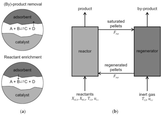
Figure 1.
Adsorptive reactors: (a) schematic principle of adsorptive reactor for enhancing conversion; (b) scheme of a dual fluidized-bed reactor–regenerator system.
A problem inherently associated with adsorption is the limited capacity of the sorbent particles, which, during the course of the process, become progressively more saturated with adsorbed molecules. This leads to a substantial decline in the adsorption rate until it eventually ceases altogether, due to the complete saturation of the pellet. Therefore, to conduct SERPs at the industrial scale, some mode of regeneration of the adsorbent particles must be applied. For classical fixed-beds, this usually means that the multifunctional reactor has to be operated in cycles of repeated reaction and regeneration stages, so that continuous synthesis demands the presence of at least two reactors in which cycles can occur interchangeably [16]. Chromatographic processes can be carried out in so-called simulated moving bed reactors (SMBRs), essentially a sub-class of fixed-bed reactors in which several columns operate through switching inlets with outlets during different stages of the process [27]. Another method consists of the implementation of circulation of solids in fluidized beds (Figure 1b). Such a solution was first used in fluid catalytic cracking (FCC) technologies, where two fluidized beds were connected in a loop that allowed for the exchange of catalyst particles between them [28,29]. In FCC, one bed is thus fluidized with feedstock and catalytic cracking reactions occur, while, in a second bed, the spent catalyst is contacted with air in order to burn off carbonaceous deposit and, simultaneously, generate heat for the main reactions. In the similarly devised SERP, one bed is fluidized with feed gas for the reaction to occur, while the second is fluidized by purge gas, so that regeneration can proceed.
The arrangement of two interconnected fluidized beds is generally known as dual (or twin)-fluidized bed, circulating bed or chemical loop, and such solutions are implemented for various processes, e.g., biomass gasification or combustion with oxygen-carriers [30,31,32], and many examples of catalytic chemical syntheses and conversions [33,34,35,36,37,38]. Such fluidized-bed reactors can not only be operated continuously, as opposed to fixed-bed adsorptive reactors, but benefit from other advantages of fluidization, such as intense heat and mass transfer, thorough the mixing and easy handling of solids that contribute to the simplicity of process control and its overall safety [39]. A simple scheme of SERP performed in a dual-fluidized-bed reactor–regenerator is presented in Figure 1b.
1.4. Hybrid Catalysts
One of the other methods of process intensification and integration involves the utilization of specially tailored catalysts with precisely designed properties, structure and active site distribution, including the incorporation of two or more kinds of active site (‘functionalities’ or simply ‘functions’) within one pellet. The first contributions to theoretical and experimental research on such hybrid catalysts date back to the early and the middle of the second half of the 20th century [40,41,42]; however, to date, hybrid catalysts remain an attractive topic for researchers, as evidenced by many recent publications dealing with issues such as optimal distribution and the ratio between functionalities in hybrid catalysts [43,44,45,46,47,48], or their general performance and comparison with various arrangements of single-function catalysts [49,50,51,52,53].
1.5. Aim of the Study
This study covers selected issues related to the steady-state properties of a dual fluidized-bed reactor–regenerator system operating in a continuous mode, with the bed made of hybrid catalyst pellets combining catalytic and adsorption sites. Considering a generic reversible chemical reaction accompanied by the physical adsorption of a by-product, the superposition of various phenomena is demonstrated, including bed hydrodynamics, mass and heat coupling of the apparatuses, and how this affects the system performance.
2. Results and Discussion
Figure 1b shows a schematic diagram of a dual fluidized-bed reactor–regenerator system that consists of an adsorptive fluidized-bed reactor and a fluidized-bed regenerator, both operating under the bubbling-bed regime. Considering the general character of this study, it is assumed that an arbitrary sorption-enhanced solid-catalyzed gas-phase exothermic chemical reaction of the type
takes place in the reactor, with C being the desired product and D being the by-product that is selectively adsorbed on adsorption sites, integrated into multifunctional (also referred to as hybrid) catalyst-adsorbent pellets. It is assumed that the chemical reaction is of the first order with respect to reactant A and B, i.e., the overall second-order; thus, the rate equation, based on unit volume of the catalyst pellet, of the chemical reaction, is
The sorption process is assumed to be at equilibrium and is described using a linear isotherm with the temperature-dependent equilibrium constant
It is assumed that continuous circulation of the pellets takes place between the reactor and the regenerator and that, in the latter, the by-product D is desorbed from the saturated pellets by hot gas.
To keep the level of the model complexity relatively simple, it is assumed that the bifunctional pellets are characterized by uniform internal distribution of two types of site. The pellet volume fractions occupied by catalytic sites, fcat, and adsorption sites, fads, are assumed to be equal; thus, fcat = fads = 0.5. A two-phase model [39,54] is employed to describe both fluidized beds with a dense phase treated as a pseudohomogeneous medium; that is, both intraparticle and interphase gradients of concentration and temperature are neglected in the description of this zone. More details concerning other assumptions of the mathematical model employed within this study, the model equations, and a description of the numerical algorithms applied, are given in Section 3.
The design, physicochemical and operating parameters used in the numerical simulations are summarized in Table 1. They were selected based on the analysis of solid-catalyzed chemical processes of industrial importance [55,56]. Given the general character of the analysis, the gas and solid properties were assumed to be the same for the reactor and the regenerator. The parameters characterizing adsorption equilibrium were derived from the experimental data available in the literature [57,58].

Table 1.
Values of the parameters used in the numerical simulations.
Considering that, in contrast to a system consisting of two or more interconnected fixed-bed reactors, the dual fluidized-bed reactor–regenerator system is meant to operate in continuous mode, the analysis presented here is limited to the steady-state behavior of the system. It should be emphasized at this point that, in the case of a single apparatus, the phenomenon of physical adsorption does not affect the values of state variables at steady state, but only their evolution in time in the transient analysis. In the case of a dual fluidized-bed system, physical sorption significantly affects the loci of steady states [59]. To illustrate this effect, the influence of the following parameters was evaluated:
- Fluidization ratio, u0,1/umf,1, determining the mean residence time of gas and the hydrodynamic conditions in the reactor;
- Entropy change, Δs, influencing the value of the chemical reaction equilibrium constant (Equation (3));
- Energetic parameter, Eads, influencing the value of the sorption equilibrium constant (Equation (5));
- Mean residence time of catalyst pellets in the regenerator, τp,2;
- Temperature of the feed gas entering the regenerator, Tf,2.
Figure 2a shows the temperature dependence of the equilibrium constant, Kp, employed within the study and defined by Equation (3). The higher the absolute value of Δs used in the calculations, the less favorable the value of the equilibrium constant of the chemical reaction. Figure 2b shows the temperature dependence of the adsorption isotherm constant, KadsD, defined by Equation (5). An increase in the value of the energetic parameter Eads results in a higher value of the adsorption isotherm constant, KadsD; thus, a higher amount of the by-product D can be adsorbed and transferred to the regenerator.
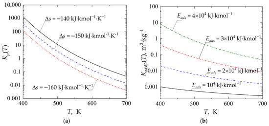
Figure 2.
Temperature dependence of: (a) chemical reaction equilibrium constant, Kp; (b) adsorption isotherm constant, KadsD.
The influence of the constant describing the adsorption/desorption equilibrium onto the performance of the dual-bed system is reported in Figure 3. The curves were determined assuming a fixed value of the fluidization ratio in the regenerator, i.e., u0,2/umf,2 = 2, and a variable value of the fluidization ratio in the reactor, u0,1/umf,1, in the range from 1 to 5, with u0,2/umf,2 = 1 corresponding to minimum fluidization conditions. The importance of physical adsorption is particularly evident in the range of lower fluidization velocity, which corresponds also to the high process temperature (Figure 3c), and thus to the unfavorable values of the equilibrium constant (Figure 2a). In this case, a continuous removal of the reaction by-product D by selective adsorption permits an increase in the production of the desired product C. In the range of low-fluidization velocities, and for the highest adopted value of Eads, the concentration of product C in the emulsion zone (Figure 3b) is more than 10% higher compared to the process carried out without simultaneous adsorption of by-product D.
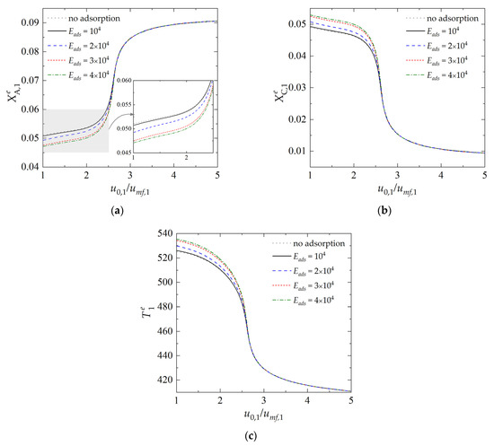
Figure 3.
Dependence of state variables in the reactor on the fluidization ratio u0,1/umf,1 for different values of Eads: (a) dimensionless concentration of component A in the emulsion (dense) zone; (b) dimensionless concentration of component C in the emulsion zone; (c) temperature of the emulsion zone. (Calculations performed with Δs = −150 kJ·kmol−1·K−1, u0,2/umf,2 = 2, τp,1 = τp,2 = 600 s and Tf,2 = 400 K; all values of Eads in the legend are expressed in kJ·kmol−1).
The effect of the equilibrium constant of the chemical reaction on the reactor performance is illustrated in Figure 4. All curves were determined assuming Eads = 3 × 10⁴ kJ·kmol−1. The ability to enhance the process by physical sorption is greatly reduced for the processes characterized by the higher absolute value of Δs, which determines the temperature dependence of Kp. As the gas velocity gets higher, and thus the temperature of the process becomes lower, the equilibrium constants assume more favorable values (Figure 2a); however, this does not lead to an increase in process performance (Figure 4a). Moreover, as can be observed, both the dimensionless concentration and temperature curves practically overlap. This is due to a reduction in the contact time between the gas and the pellets, which, in turn, reduces the overall process rate.
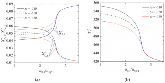
Figure 4.
Dependence of state variables in the reactor on the fluidization ratio u0,1/umf,1 for different values of Δs: (a) dimensionless concentration of components A and C in the emulsion (dense) zone; (b) temperature of the emulsion zone. (Calculations performed with Eads = 3 × 10⁴ kJ·kmol−1, u0,2/umf,2 = 2, τp,1 = τp,2 = 600 s and Tf,2 = 400 K; all values of Δs in the legend are expressed in kJ·kmol−1·K−1).
Another group of parameters that have a strong influence on the steady-state behavior of the dual fluidized-bed reactor–regenerator system are the parameters related to the geometry (reactor and regenerator sizes) and the circulation mass flow rate of the pellets between two apparatuses. To demonstrate the effect of the bed geometry on the system behavior, the model equations were solved for varying values of the mean residence time of pellets in the regenerator, τp,2, in the range from 200 s to 1200 s. At a constant circulation rate of the catalyst pellets between reactor and regenerator, change in the mean residence time of the pellets in the regenerator (defined by Equation (27)) is equivalent to the change in the bed load in the regenerator with respect to the bed load in the reactor.
Figure 5 reports the solution curves as a function of τp,2, obtained for several values of the feed gas temperature, to the regenerator, Tf,2, and fixed values of Eads and Δs in the expressions determining chemical and adsorption equilibrium. It can be observed that, for the lowest value of Tf,2 = 400 K and in case of the adoption of too-high values for the mean residence time of the pellets in the regenerator, there is an almost complete extinction of the process. This is due to the excessive cooling of the pellets in the regenerator. Increasing the temperature of the feed inert gas to the regenerator, Tf,2, helps to avoid the risk of extinction and, at the same time, to boost the desorption of the by-product in the regenerator, and thus the regeneration of the catalyst pellets.
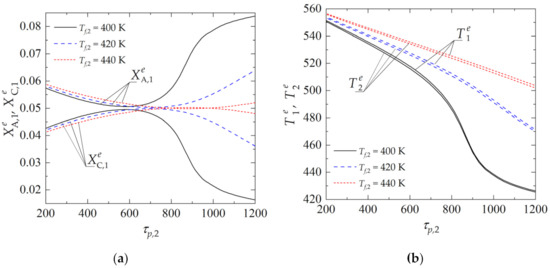
Figure 5.
Dependence of state variables in the reactor (j = 1) and regenerator (j = 2) on the mean residence time of catalyst pellets in the regenerator τp,2 for different values of Tf,2: (a) dimensionless concentration of component A and C in emulsion (dense) zone in the reactor; (b) temperature of the emulsion zone in the reactor and in the regenerator. (Calculations performed with Eads = 3 × 10⁴ kJ·kmol−1, Δs = −150 kJ·kmol−1·K−1, u0,1/umf,1 = u0,2/umf,2 = 2 and τp,1 = 600 s).
3. Materials and Methods
3.1. Mathematical Model of a Dual Fluidized-Bed Reactor–Regenerator System
In this work, a two-phase model [39,54] was adopted for quantitative and qualitative description of a dual fluidized-bed reactor–regenerator system (Figure 1b), with both beds operating under the bubbling regime. Other assumptions are as follows:
- The two phases, i.e., the bubble zone and the dense zone (also referred to as emulsion zone), are distinguished in both fluidized beds, whereas intraparticle and gas–solid mass and heat transfer resistances are neglected in the description of the dense zone;
- Ideal mixing of gas in the emulsion zone, both in the reactor and in the regenerator;
- Plug flow of gas in the bubble zone, both in the reactor and in the regenerator, and quasi-steady state character of the bubble zone;
- Gas bubbles are spherical and they have a constant diameter along the bed height in both reactor units;
- Both fluidized-bed units operate adiabatically;
- Chemical process takes place only in the emulsion zone of the reactor, while physical sorption occurs both in the reactor and in the regenerator which is fed with a hot inert gas;
- The gas volume change due to chemical reaction and physical adsorption is neglected, given the high content of inert gas;
- The sorption process is assumed to be at equilibrium and is described using a linear isotherm;
- The rate of increase of the catalyst pellet energy does not vary significantly for contributions of the heat of adsorption, of the intraparticle gas phase and of the adsorbed phase heat capacities, which are thus neglected.
The correlations employed to determine the hydrodynamic properties of the fluidized beds, and the mass and heat interchange coefficients between the bubble zone and the emulsion zone, are reported in Table 2.
Table 2.
Hydrodynamic properties and interchange coefficients in the fluidized bed.
In accordance with the above assumptions, the mass and heat balance equations of the dual fluidized-bed reactor–regenerator system can be written as follows
with the following initial conditions describing the values of concentrations and temperatures in the emulsion zone in the reactor and regenerator at system start-up
In the model equations formulated above, subscript i refers to the component, i.e., i = A, B, C, D. Subscripts 1 and 2 of the state variables Xe and Te refer, respectively, to the reactor (j = 1) and to the regenerator (j = 2), with Xe being a dimensionless concentration defined as
The expression describing the rate of chemical reaction in terms of the dimensionless concentrations of the reactants is defined as
Functions ϕ1i,j and ϕ2,j resulting from concentration and temperature distributions [64] in the bubble zone, for which a quasi-steady state assumption is made, are described by the following expressions
where:
Coefficients D1i,j and D2,j (i = A, B, C, D; j = 1, 2) in Equations (15)–(18), describing the rate of the mass and heat interchange between the two beds, are defined as
where τp,j denotes mean residence time of the pellets in apparatus j, and is defined as
The other parameters appearing in Equations (15)–(23) are defined as follows
Full description of a method for the determination of the hydrodynamic characteristics of a fluidized bed, and other details related to the formulation of the mathematical model, are given in references [59,64,65].
3.2. Solution Procedure
Given that the dual fluidized-bed reactor–regenerator system is meant to operate in a continuous mode, the analysis is limited to steady-state behavior of the system. Determination of the parametric dependencies of state variables at steady state comes down to the numerical resolution of Equations (15)–(18) with the time derivatives on the left-hand side of the equations set to zero, and for a varying value of a selected model parameter. The system of 10 nonlinear algebraic equations describing the behavior of the dual fluidized-bed system was solved using the built-in function fsolve of MATLAB. The hydrodynamic characteristic of the fluidized bed was determined following the algorithm reported in [64] and submerged in the fsolve procedure. The algorithm can simultaneously calculate a dynamic bed height H, a diameter of bubbles db, a bubble rise velocity ub, and a volume fraction of the bubbles in the fluidized bed δ. The parametric dependencies of the state variables were determined using natural parameter continuation.
4. Conclusions
The analysis shows that a dual fluidized-bed reactor–regenerator system is an attractive solution that allows the SERPs to be run in continuous mode. Such an arrangement can eliminate a problem inherently associated with sorption-enhanced processes run in fixed-bed reactors, typically operating in transient and/or cyclic regime.
Anyhow, due to the complex hydrodynamics of the fluidized bed affecting both heat and mass transfer, as well as the gas–solid contact time, and due to the strong temperature dependence of the chemical reaction equilibrium constant and of the adsorption isotherm equilibrium constant, the selection of the optimal operating parameters of the dual bed system turns out to be a challenging task. Using a generic reversible chemical reaction catalyzed by bifunctional pellets integrating catalytic active sites and adsorption sites as an example, the effect of variations in selected parameters on the system performance was illustrated. It was demonstrated that too-low values of the fluidization velocity may lead to an excessive increase in the bed temperature, which cancels out the benefits of incorporating adsorption sites into the pellet. On the other hand, too-short gas–solid contact time may lead to the process extinction. Another critical parameter is the mean residence time of the pellets in the regenerator: although high-enough values are required to regenerate the pellets, this may also lead to their excessive cooling, which, in turn, may lower the overall process rate. The model developed is a candidate for use in systematic optimization procedures.
Author Contributions
Conceptualization, K.B.; methodology, K.B. and K.S.-M.; software, K.B.; validation, K.B. and K.S.-M.; investigation, K.B., K.S.-M. and M.P.; data curation, K.B. and K.S.-M.; writing—original draft preparation, K.B. and K.S.-M.; writing—review and editing, K.B., K.S.-M. and M.P.; visualization, K.B. and M.P.; funding acquisition, K.B. All authors have read and agreed to the published version of the manuscript.
Funding
The research was financed by the Polish National Science Centre, project number 2017/26/D/ST8/00509.
Data Availability Statement
Data available on request.
Conflicts of Interest
The authors declare no conflict of interest.
Nomenclature
| cg, cs | specific heat of gas and solid, respectively, kJ∙kg−1∙K−1 |
| C | molar concentration, kmol∙m−3 |
| db | effective bubble diameter, m |
| dp | catalyst pellet diameter, m |
| Db,i | diffusion coefficient of reactant i in the bubble zone, m2∙s−1 |
| De,i | diffusion coefficient of reactant i in the emulsion zone, m2∙s−1 |
| Eads | energetic parameter characterizing physical adsorption, kJ∙kmol−1 |
| E | activation energy of chemical reaction, kJ∙kmol−1 |
| fads | volume fraction of the pellet occupied by adsorption sites |
| fcat | volume fraction of the pellet occupied by catalytic active sites |
| Fmp | circulation rate of catalyst pellets, kg∙s−1 |
| Δh | enthalpy of chemical reaction, kJ∙kmol−1 |
| H | total height of a fluidized bed, m |
| k01 | frequency coefficient in the Arrhenius equation, m3·kmol−1·s−1 |
| Kads | adsorption isotherm equilibrium constant, m3⋅kg−1 |
| Kads,0 | pre-exponential factor of the adsorption isotherm equilibrium constant, m3⋅kg−1 |
| Kp | chemical reaction equilibrium constant |
| P | pressure, Pa |
| q | amount of reactant adsorbed on the adsorption sites, kmol∙kg−1 |
| r | chemical reaction rate, kmol∙m−3∙s−1 |
| R | universal gas constant, kJ∙kmol−1∙K−1 |
| Δs | entropy change in the chemical reaction, kJ∙kmol−1∙K−1 |
| S | cross section of a fluidized bed, m2 |
| t | time, s |
| T | temperature, K |
| u | velocity, m∙s−1 |
| u0 | superficial gas velocity, m∙s−1 |
| X | dimensionless concentration |
| z | dimensionless coordinate in a fluidized bed |
| Greek symbols | |
| coefficient of heat interchange between zones i and j, kW∙m−3∙K−1 | |
| coefficient of interchange of reactant k between zones i and j, s−1 | |
| coefficient of catalyst particles interchange between zones i and j, s−1 | |
| δ | volume fraction of bubbles in a fluidized bed |
| εmf | void fraction of a fluidized bed at minimum fluidization conditions |
| εp | porosity of a catalyst pellet |
| λg | thermal conductivity of gas, kW·m−1·K−1 |
| μg | dynamic viscosity, Pa∙s |
| ν | stoichiometric coefficient |
| ρg | gas density, kg∙m−3 |
| ρp | density of catalyst pellets, kg∙m−3 |
| τp | mean residence time of the pellets in the apparatus, s |
| Subscripts and superscripts | |
| 1, 2 | refers to reactor and regenerator, respectively |
| b | refers to bubble zone |
| bulk | refers to bulk gas |
| e | refers to emulsion zone |
| f | refers to feed stream |
| mf | refers to minimum fluidization conditions |
| p | refers to catalyst particle |
| ref | refers to reference conditions |
| t | refers to terminal conditions |
References
- Oxford Economics. The Global Chemical Industry: Catalyzing Growth and Addressing Our World’s Sustainability Challenges; International Council of Chemical Associations: Brussels, Belgium, 2019. [Google Scholar]
- Lines, M. Addresing sustainability in the chemical industry. In Transforming Sustainability Strategy into Action: The Chemical Industry; Beloff, B., Lines, M., Tanzil, D., Eds.; John Wiley & Sons, Inc.: New York, NY, USA, 2005; pp. 8–10. [Google Scholar]
- International Energy Agency; International Council of Chemical Associations; DECHEMA Gesselshaft fur Chemische Technik und Biotechnologie. Technology Roadmap: Energy and GHG Reductions in the Chemical Industry via Catalytic Processes; International Energy Agency: Paris, France, 2013. [Google Scholar]
- Boulamanti, A.; Moya, J.A. Energy Efficiency and GHG Emissions: Prospective Scenarios for the Chemical and Petrochemical Industry; Publications Office of the European Union: Luxembourg, 2017. [Google Scholar] [CrossRef]
- OECD. OECD Environmental Outlook for the Chemicals Industry; Organisation for Economic Co-operation and Development: Paris, France, 2001. [Google Scholar]
- National Research Council. Sustainability in the Chemical Industry: Grand Challenges and Research Needs; The National Academies Press: Washington, DC, USA, 2006. [Google Scholar]
- Garcia-Serna, J.; Perez-Barrigon, L.; Cocero, M.J. New trends for design towards sustainability in chemical engineering: Green engineering. Chem. Eng. J. 2007, 133, 7–30. [Google Scholar] [CrossRef]
- Hall, G.M.; Howe, J. Sustainability of the chemical manufacturing industry—Towards a new paradigm? Educ. Chem. Eng. 2010, 5, 100–107. [Google Scholar] [CrossRef]
- Leszczyński, Z. Role of chemical engineering and chemical process machinery in industrial application and in process intensification. Przem. Chem. 1973, 52, 161–163. [Google Scholar]
- Ramshaw, C. Higee distillations—An example of process intensification. Chem. Eng. (Lond.) 1983, 389, 13–14. [Google Scholar]
- Ramshaw, C.; Arkley, K. Process intensification by miniature mass transfer. Process Eng. 1983, 64, 29–31. [Google Scholar]
- Boffito, D.C.; Fernandez Rivas, D. Process intensification connects scales and disciplines towards sustainability. Can. J. Chem. Eng. 2020, 98, 2489–2506. [Google Scholar] [CrossRef]
- Stankiewicz, A.I.; Mouljin, J.A. Process intensification: Transforming chemical engineering. Chem. Eng. Prog. 2010, 96, 22–33. [Google Scholar]
- Stankiewicz, A.; Drinkenburg, A.A.H. Process intensification: history, philosophy, principles. In Re-Engineering the Chemical Processing Plant: Process Intensification, 1st ed.; Stankiewicz, A., Mouljin, J.A., Eds.; Marcel Dekker: New York, NY, USA, 2004; pp. 14–40. [Google Scholar]
- Keil, F.J. Modeling of Process Intensification—An Introduction and Overview. In Modeling of Process Intensification, 1st ed.; Keil, F., Ed.; Wiley-VCH: Weinheim, Germany, 2007; pp. 9–24. [Google Scholar]
- Carvill, B.T.; Hufton, J.R.; Anand, M.; Sircar, S. Sorption-enhanced reaction process. AIChE J. 1996, 42, 2765–2772. [Google Scholar] [CrossRef]
- Hufton, J.R.; Mayorga, S.; Sircar, S. Sorption-enhanced reaction process for hydrogen production. AIChE J. 1999, 45, 248–256. [Google Scholar] [CrossRef]
- Xiu, G.-H.; Ping, L.; Rodrigues, A.E. Sorption-enhanced reaction process with reactive regeneration. Chem. Eng. Sci. 2002, 57, 3893–3908. [Google Scholar] [CrossRef]
- Soo, I.I.; Ki, B.L. Novel sorption-enhanced methanation with simultaneous CO2 removal for the production of synthetic natural gas. Ind. Eng. Chem. Res. 2016, 55, 9244–9255. [Google Scholar] [CrossRef]
- Borgschulte, A.; Gallandat, N.; Probst, B.; Suter, R.; Callini, E.; Ferri, D.; Arroyo, Y.; Erni, R.; Geerlings, H.; Zuttel, A. Sorption-enhanced CO2 methanation. Phys. Chem. Chem. Phys. 2013, 15, 9620–9625. [Google Scholar] [CrossRef] [PubMed]
- van Selow, E.R.; Cobden, P.D.; Verbraeken, P.A.; Hufton, J.R.; van den Brink, R.W. Carbon capture by sorption-enhanced water-gas shift reaction process using hydrotalcite-based material. Ind. Eng. Chem. Res. 2009, 48, 4184–4193. [Google Scholar] [CrossRef]
- van Selow, E.R.; Cobden, P.D.; van den Brink, R.W.; Hufton, J.R.; Wright, A. Performance of sorption-enhanced water-gas shift as a pre-combustion CO2 capture technology. Energy Procedia 2009, 1, 689–696. [Google Scholar] [CrossRef]
- van Dijk, H.A.J.; Walspurger, S.; Cobden, P.D.; Jansen, D.; van den Brink, R.W.; de Vos, F.G. Performance of water-gas shift catalysts under sorption-enhanced water-gas shift conditions. Energy Procedia 2009, 1, 639–646. [Google Scholar] [CrossRef][Green Version]
- Elsner, M.P.; Menge, M.; Muller, C.; Agar, D.W. The claus process: Teaching an old dog new tricks. Catal. Today 2003, 79–80, 487–494. [Google Scholar] [CrossRef]
- Iliuta, I.; Iliuta, M.C.; Larachi, F. Sorption-enhanced dimethyl ether synthesis—Multiscale reactor modelling. Chem. Eng. Sci. 2011, 66, 2241–2251. [Google Scholar] [CrossRef]
- Guffanti, S.; Visconti, C.G.; van Kampen, J.; Boon, J.; Groppi, G. Reactor modelling and design for sorption-enhanced dimethyl ether synthesis. Chem. Eng. J. 2021, 126573:1–126573:13. [Google Scholar] [CrossRef]
- Constantino, D.S.M.; Faria, R.P.V.; Rodrigues, A.E. Sorption-enhanced reaction with simulated moving bed reactor and PermSMBR technologies. In Advances in Chemical Engineering. Sorption Enhancement of Chemical Processes; Lemonidou, A.A., Ed.; Academic Press: Cambridge, MA, USA, 2017; pp. 261–330. [Google Scholar] [CrossRef]
- Squires, A.M. The story of fluid catalytic cracking: The first “circulating fluid bed”. In Proceedings of the First International Conference on Circulating Fluidized Beds, Halifax, NS, Canada, 18–20 November 1985; Basu, P., Ed.; Pergamon Press: Oxford, UK, 1986; pp. 1–19. [Google Scholar] [CrossRef]
- Fletcher, R.P. The history of Fluidized Catalytic Cracking: A history of innovation: 1942–2008. In Innovations in Industrial and Engineering Chemistry. A Century of Achievements and Prospects for the New Millennium; Flank, W.H., Abraham, M.A., Matthews, M.A., Eds.; American Chemical Society: Washington, DC, USA, 2009. [Google Scholar] [CrossRef]
- Pfeifer, C.; Puchner, H.; Hofbauer, H. Comparison of dual fluidized bed steam gasification of biomass with and without selective transport of CO2. Chem. Eng. Sci. 2009, 64, 5073–5083. [Google Scholar] [CrossRef]
- Mattison, T.; Lyngfelt, A.; Leion, H. Chemical looping with oxygen coupling for combustion of solid fuels. Int. J. Greenh. Gas. Control. 2009, 3, 189–200. [Google Scholar] [CrossRef]
- Penthor, S.; Mayer, K.; Kern, S.; Kitzler, H.; Woss, D.; Proll, T.; Hofbauer, H. Chemical-looping combustion of raw syngas from biomass steam gasification—Coupled operation of two dual fluidized bed pilot plants. Fuel 2014, 127, 178–185. [Google Scholar] [CrossRef]
- Johnsen, K.; Grace, J.R.; Elnashaie, S.S.E.H.; Kolbensein, L.; Eriksen, D. Modelling of sorption-enhanced steam reforming in dual fluidized bubbling bed reactor. Ind. Eng. Chem. Res. 2006, 45, 4133–4144. [Google Scholar] [CrossRef]
- Gayubo, A.G.; Ortega, J.M.; Aguayo, A.T.; Arandes, J.M.; Bilbao, J. MTG fluidized bed reactor-regenerator unit with catalyst circulation: Process simulation and operation of an experimental setup. Chem. Eng. Sci. 2000, 55, 3223–3235. [Google Scholar] [CrossRef]
- Yang, X.; Wang, S.; Li, B.; Liu, H.; He, Y. Evaluation of sorption-enhanced reforming over catalyst-sorbent bi-functional particles in an internally circulating fluidized bed. Adv. Powder Technol. 2020, 31, 2566–2572. [Google Scholar] [CrossRef]
- Ju, Y.; Oh, H.-T.; Lee, J.-C.; Lee, C.-H. Performance and dynamic behaviour of sorption-enhanced water-gas shift reaction in a fluidized bed reactor for H2 production and CO2 capture. Chem. Eng. J. 2020, 127414. [Google Scholar] [CrossRef]
- Arstad, B.; Blom, R.; Bakken, E.; Dahl, I.; Jakobsen, J.P.; Rokke, P. Sorption-enhanced methane steam reforming in a circulating fluidized bed reactor system. Energy Procedia 2009, 1, 715–720. [Google Scholar] [CrossRef]
- Contractor, R.M. Dupont’s CFB technology for maleic anhydride. Chem. Eng. Sci. 1999, 54, 5627–5632. [Google Scholar] [CrossRef]
- Kunii, D.; Levenspiel, O. Fluidization Engineering, 2nd ed.; Butterworth-Heinemann: Newton, MA, USA, 1991. [Google Scholar] [CrossRef]
- Ciapetta, F.G. Isomerization of saturated hydrocarbons: Nature of the catalyst and mechanism of the reaction. Ind. Eng. Chem. 1953, 45, 162–165. [Google Scholar] [CrossRef]
- Gunn, D.J.; Thomas, W.J. Mass transport and chemical reaction in multifunctional catalyst systems. Chem. Eng. Sci. 1965, 20, 89–100. [Google Scholar] [CrossRef]
- Choi, C.Y.; Perlmutter, D.D. On singular policies in the optimal distribution of a bifunctional catalyst: Part II. Effect of diffusional and mass transfer resistances. AIChE J. 1978, 24, 193–203. [Google Scholar] [CrossRef]
- Dietrich, W.; Praveen, S.L.; Grunewald, M.; Agar, D.W. Theoretical studies on multifunctional catalysts with integrated adsorption sites. Chem. Eng. J. 2005, 107, 103–111. [Google Scholar] [CrossRef]
- Grunewald, M.; Agar, D.W. Enhanced catalyst performance using integrated structured functionalities. Chem. Eng. Sci. 2004, 59, 5519–5526. [Google Scholar] [CrossRef]
- Lugo, E.L.; Wilhite, B.A. A theoretical comparison of multifunctional catalyst for sorption-enhanced reforming process. Chem. Eng. Sci. 2016, 150, 1–15. [Google Scholar] [CrossRef]
- Bizon, K.; Skrzypek-Markiewicz, K.; Pędzich, D.; Reczek, N. Intensification of catalytic processes through the pellet structuring: Steady-state properties of a bifunctional catalyst pellets applied to generic chemical reactions and the direct synthesis of DME. Catalysts 2020, 9, 1020. [Google Scholar] [CrossRef]
- Bizon, K.; Continillo, G.; Skrzypek-Markiewicz, K. Enhancement of the direct synthesis of dimethyl ether (DME) from synthesis gas by macro- and microstructuring of the catalytic bed. Catalysts 2020, 10, 852. [Google Scholar] [CrossRef]
- Guffanti, S.; Visconti, C.G.; Groppi, G. Model analysis of the effects of active phase distribution at the pellet scale in catalytic reactors for the direct dimethyl ether synthesis. Ind. Eng. Chem. Res. 2020, 59, 14252–14266. [Google Scholar] [CrossRef]
- Park, H.W.; Chung, J.S.; Baeck, S.-H.; Song, I.K. Physical property and chemical composition distribution of ethylene-hexene copolymer produced by metallocene/Ziegler-Natta hybrid catalyst. J. Mol. Catal. A Chem. 2006, 255, 69–73. [Google Scholar] [CrossRef]
- Albrecht, K.O.; Satrio, J.A.; Shanks, B.H.; Wheelock, T.D. Application of a combined catalyst and sorbent for steam reforming of methane. Ind. Eng. Chem. Res. 2010, 49, 4091–4098. [Google Scholar] [CrossRef][Green Version]
- Congming, L.; Ban, H.; Cai, W.; Zhang, Y.; Li, Z.; Fujimoto, K. Direct synthesis of iso-butane from synthesis gas or CO2 over CuZnZrAl/Pd-beta hybrid catalyst. J. Saudi Chem. Soc. 2017, 21, 974–982. [Google Scholar] [CrossRef]
- Tao, J.-L.; Jun, K.-W.; Lee, K.-W. Co-production of dimethyl ether and methanol from CO2 hydrogenation: Development of a stable hybrid catalyst. Appl. Organometal Chem. 2001, 15, 105–108. [Google Scholar] [CrossRef]
- Adeleke, A.A.; Liu, X.; Lu, X.; Moyo, M.; Hildebrant, D. Cobalt hybrid catalysts in Fischer-Tropsch synthesis. Rev. Chem. Eng. 2018, 36, 437–457. [Google Scholar] [CrossRef]
- Tabiś, B. Methanol synthesis in a fluidized-bed reactor coupled with an external heat exchanger. The effect of feedback deformation. Chem. Eng. J. 2001, 83, 191–200. [Google Scholar] [CrossRef]
- Hlaváček, V.; Kubíček, M.; Marek, M. Analysis of nonstationary heat and mass transfer in a porous catalyst particle I. J. Catal. 1969, 15, 17–30. [Google Scholar] [CrossRef]
- Balakotaiah, V.; West, D.H. Thermal effects and bifurcations in catalytic partial oxidations. Curr. Opin. Chem. Eng. 2014, 5, 68–77. [Google Scholar] [CrossRef]
- Shen, J.; Smith, J.M. Adsorption isotherms for benzene-hexane mixtures. Ind. Eng. Chem. Fund. 1968, 7, 100–105. [Google Scholar] [CrossRef]
- Zhou, X.; Yi, H.; Tang, X.; Deng, H.; Liu, H. Thermodynamics for the adsorption of SO2, NO and CO2 from flue gas on activated carbon fiber. Chem. Eng. J. 2012, 200, 399–404. [Google Scholar] [CrossRef]
- Bizon, K. Effect of reactant adsorption on the stationary and dynamic characteristics of a catalytic fluidized-bed reactor coupled with a fluidized-bed heat exchanger. Przem. Chem. 2019, 98, 1000–1004. [Google Scholar] [CrossRef]
- Broadhurst, T.E.; Becker, H.A. Onset of fluidization in slugging beds of uniform particles. AIChE J. 1975, 21, 238–247. [Google Scholar] [CrossRef]
- Razumov, I.M. Fluidization and Pneumatic Transport of Bulk Materials; WNT: Warszawa, Poland, 1975. [Google Scholar]
- Kobayashi, A.C. Behaviour of bubbles in gas fluidized bed. Kagaku Kogaku Ronbunshu 1965, 29, 858–863. [Google Scholar] [CrossRef][Green Version]
- Kunii, D.; Levenspiel, O. Bubbling bed model for kinetic processes in fluidized beds. Gas-solid mass and heat transfer and catalytic reactions. Ind. Eng. Chem. Proc. Des. Dev. 1968, 7, 481–492. [Google Scholar] [CrossRef]
- Bizon, K. Autothermicity, multiplicity, yield and selectivity of catalytic processes in a polytropic fluidized bed reactor. Chem. Eng. J. 2016, 288, 834–844. [Google Scholar] [CrossRef]
- Bizon, K. Nonlinear Analysis of the Dynamics of Fluidized-Bed Autothermal Structures; Wydawnictwo Politechniki Krakowskiej: Cracow, Poland, 2017. [Google Scholar]
Publisher’s Note: MDPI stays neutral with regard to jurisdictional claims in published maps and institutional affiliations. |
© 2021 by the authors. Licensee MDPI, Basel, Switzerland. This article is an open access article distributed under the terms and conditions of the Creative Commons Attribution (CC BY) license (https://creativecommons.org/licenses/by/4.0/).