1. Introduction
Mathematical models of full processes, single apparatus, devices, etc. are presented in many or even the majority of recently published scientific papers. There are presented as experimental and theoretical, sophisticated, and simple models. They can differ from each other in terms of precision, complexity, application range, and many other features. The diversity of models presented in the literature is easily understood: modeling, which provides tools that can improve understanding of the process, allows increasing profits or decreasing costs. However, the most frequently published models are developed to describe small-scale processes. Models created and successfully tested on a commercial scale are only exceptionally presented. There are many reasons for such a situation. We shall concentrate on two aspects: mathematical model structure and experiment conduction.
The first aspect is the structure of the commonly presented mathematical models. The commonly accepted classification is as follows:
- (i)
the empirical type, which is obtained by fitting experimental data; the models are relatively easy to develop and solve;
- (ii)
the semiempirical type, developed using the principles of chemistry and physics with some parameters calculated from experimental data;
- (iii)
the theoretical model, developed using the principles of chemistry and physics and all parameters calculated with the principles as well, practically unused in chemical reactor engineering problems
Category (i) models are usually used to describe commercial processes in which the emphasis is on the precision of prediction, while operating conditions deviate within specified ranges. Developed equations often vary from theoretical ones and can only be applied within the experimental range (see: kinetic equation for the process under consideration [
1]). Semi-empirical models (category (ii)) are most often used in practical applications. They combine the precision of empirical models with a broad range of applications of theoretical ones; however, they are usually more complex compared to empirical models. Semi-empirical models can be both simple and sophisticated, and easy and hard to solve. They involve many parameters; some of these should be determined experimentally (see examples in the chemical reactor engineering field: the pseudohomogeneous versus heterogeneous model of the heterogeneous fixed-bed reactor [
2], and polymerization of vinyl acetate emulsion in a real-life industrial reactor [
3]). In our opinion, the conscious choice of a model structure is a crucially important factor for modeling complex industrial objects. Few reports on this topic are presented in textbooks, while the attention authors of the articles are mainly focused on the solved problem, not on the model. However, especially for complex models i.e., real-life industrial ones, it can be advisable and helpful to consider the impact of a model structure on the complexity of the solution and its precision.
The second aspect is the experiment conduction for research purposes. Neglecting the costs associated with investigations, we would like to discuss some points about experimental work and the interpretation of results. Fundamental differences are observed between the needs of researchers and instrumentation and measurement capabilities for large-scale industrial apparatus. For example, in the case of the process under consideration, 1. the reactor is of multitubular type, and the measurements should be made for all tubes separately; 2. the real process runs for several years until full deactivation of the catalyst bed and measurements should be made frequently during the full operation period while the inlet composition should not vary with time; 3. mass and heat transfer coefficients should be precisely determined for the reactor, etc. These tasks are simply impossible to do. The limited amount of information on a process makes modeling more difficult, but it should not fail to create a model. The remedies applied most often for these unfavorable circumstances are investigations on a small scale in separate experiments (e.g., the kinetics of reaction) or calculation of transport coefficients by correlations, or both. We propose an alternative procedure, which we applied with successful results for the investigation of benzene hydrogenation.
In our opinion, in the case where limitations in experimental capabilities are present (a typical problem for large-scale processes), the crucial importance for successful modeling is developing the model process and its tuning as well as the estimation of proper values of model parameters. Our approach to the proper model development problem can be characterized by the well-known Einstein’s aphorism “Make things as simple as possible, but not simpler”. For this reason, we start from relatively simple models to gain practical knowledge and necessary experience. Next, the model is subsequently extended to improve precision until satisfactory accuracy is attained consistently. Additionally, we suggest the estimation of model parameters based on experimental results. Estimating model parameters is a well-known and useful method applied with successful results in other chemical engineering branches, among others, in chromatography. It allows in a relatively simple way to complete the data or to correct the results of experiments. Theoretical aspects and practical applications can be found in numerous works given by Kaczmarski and co-workers [
4,
5].
The article’s goal is to designate the reactor operating conditions that eventually determine the process windows for the reactor, taking into account the process of deactivation by sorption of sulfur compounds that are present in the inlet stream. The goal was realized, and the results are presented in
Section 5. Additionally, we present an outline of the main ideas of the model application.
Modeling of industrial reactors, especially fixed-bed heterogeneous ones, is relatively rarely presented in the literature; however, some recent progress can be observed. Aside from saving confidential data, this scarcity results from the complexity of the problem. The mathematical description of large-scale apparatus with consideration of microscale phenomena (e.g., mass or heat transfer) as well as processes of the same type but with different timescales (e.g., main reaction vs. deactivation) is a real challenge. Despite the fact that general rules of reactor modeling are well-known, in practice, each case requires individual treatment. As a result, single articles concerning the specified process and specified types of reactors of industrial-scale can be found in the literature. Additionally, the complexity of the problems lies in the fact that the authors mainly focus on selected aspects of processes or reactors, rather than a comprehensive analysis. Hence, the application of other authors’ models to our own problem is a difficult task. Then, again, authors often show readers a detailed description of methods used, stages of model building, or its refinement that helps to solve their own problems. We would like to focus attention on a few articles. Navalho et al. [
6] presented a full methodology combining three different reactor length scales to investigate the role of the catalyst internal pore structure, metal loading, and dispersion. The multiscale methodology applied helps investigate the effect of morphological and catalytic details on full-scale reactor operation. The authors recommended their methodology for catalyst optimization studies. Nawaz [
7] presented a one-dimensional heterogeneous model of an industrial multitubular packed-bed ethylene oxide reactor for its successful validation. The model presented predicts the behavior of the main reaction and allows the analysis of important parameters such as yield, by-product formation, temperature, and concentration profiles. The model was used to optimize ethylene oxide production and to enhance the safety of reactor operations. Timaeus et al. [
8] presented a model of an inclined rotating fixed bed reactor for hydrogenation of α-methylstyrene. The authors analyzed the influence of period length and different wetting–draining cycles on the space-time yield of the reactor. Based on the simulations made, the authors claimed that the results reveal that high rotational velocities should be applied for reaction kinetics that depend on the liquid educt concentration. The model can be also helpful to determine the process windows for the concept of an advanced reactor. The behavior of industrial fixed bed reactors for the manufacture of maleic anhydride was investigated by Lesser et al. [
9]. They presented a detailed model for the oxidation of n-butane in fixed bed reactors. The model helps to test various interactions between phosphorus and water. To obtain a better fit between simulations and experiments, they corrected the correlations concerning wall heat transfer coefficient and pressure drop. The model presented was successfully applied to fixed bed pilot reactor experiments over 500 h. Raju et al. [
10] presented a design methodology and thermal modeling of an industrial-scale reactor for solid-state hydrogen storage. A 3-D numerical model has been developed using the COMSOL Multiphysics platform to predict the hydriding performance of designed reactors. A novel set of comprehensive correlations has been developed and, based on these correlations, various reactor configurations were designed. Che-Galicia et al. [
11] tested the role of kinetics and heat transfer on the performance of an industrial wall-cooled packed-bed reactor for oxidative dehydrogenation of ethane. They presented rigorous methodologies to characterize the kinetics and heat transfer mechanisms using statistical and phenomenological criteria to model an industrial-scale, wall-cooled packed-bed reactor. The authors claim that the successful design, optimization, or intensification of a reactor requires a proper characterization of both kinetics and heat transfer mechanisms. They also presented a few interesting observations concerning the catalyst surface that remained reduced in the reactor length, and the coverage of the oxidized sites on the catalyst surface was close to zero.
The above review shows that there is no single way to ensure a successful result of modeling an industrial reactor. The authors applied various methods and techniques to improve the precision and obtain satisfactory results: 1-D models such as [
7,
11], 3-D models [
10], commercial computational platforms [
7,
10] and their own methods (e.g., [
11]), theoretical [
9,
11] and empirical [
7,
8] kinetic equations, improved correlations [
9] and theoretical relationships [
6], etc. On the other hand, the papers indicate the major role of kinetic equation and mass and heat transfer. Taking these papers and our own experience into account, we would like to increase the knowledge and join the presented research stream by exhibiting our way to the successful modeling of an industrial reactor for the hydrogenation of benzene. Presentation of the reactor model and optional forms of action taken is the second goal of the paper. We present a step-by-step procedure for developing a reactor model for the large-scale process, i.e., hydrogenation of benzene to cyclohexane, and some results obtained with the model application. The final version of the model obtained is presented in detail, and the comparison of the results with experiments (i.e., verification of the model) is shown. In the literature, there were no attempts to model a long-time reactor operation if the catalyst bed is deactivated by sorption of compounds that are present in the inlet stream and if the reaction zone moves along the reactor, to the best of our knowledge. Our work fills this gap.
Hydrogenation of benzene to cyclohexane is an important case of large-scale chemical processes. The reaction is described by the equation
Hydrogenation of benzene is the predominant method of cyclohexane production, accounting for 100% of the world’s cyclohexane capacity. Since high-purity cyclohexane is required for caprolactam and most adipic acid production, the higher-purity benzene-derived material is far more important commercially. The global cyclohexane market is foreseen to grow considerably over the nearest period (the market value forecast in 2027 is over USD 34 billion), supported by numerous favorable factors, including the increasing industrial uses of nylon, especially in the textiles and automotive industries. It should be pointed out that improvements in the process run, related to operating conditions, catalyst application, or both on account of the high scale of the process and its expected growth will remarkably influence both the profits and the environmental protection.
2. Results and Discussion
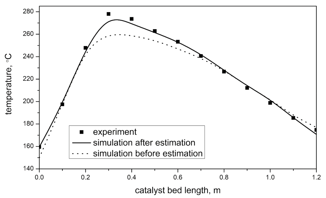
The presented model of the benzene hydrogenation reactor was verified according to point 3 of the investigation scheme. The results of the simulation were compared with single unit tube temperature measurements and are presented in
Figure 1. This figure also presents the difference between the results obtained before and after model improvement. The dotted line shows the predicted temperature profile for transport coefficients calculated from Equations (45)–(48). Tests for the model sensitivity concerning the values of the transport parameters were made. To this aim, other commonly accepted correlations were employed for the calculation of mass and heat coefficients. The parameters can vary in a relatively wide range and with no change in results. It shows that the model is not sensitive to the transport coefficient changes.
The accuracy was good, with the maximal error reaching 8% in the reaction zone (maximum temperature). The largest differences in temperature profile appeared in the reaction zone. As a result, a lower accuracy of prediction of gas composition could be observed. Obtained results confirm that the choice of the model type was correct, but either some coefficients were imprecisely determined or factors undefined in the model (such as fluctuations of inlet composition and temperature, coke deposition, and catalyst aging) influence the reactor’s behavior. Regardless of the source of the inaccuracy, the estimation of parameter values can be used to improve the model precision. Analysis of the simulation results concludes that a simple adjustment of the heat transfer coefficient that influences the heat exchange between the reactor and the surrounding should help improve the model precision. The authors’ computer program helps estimate another value of constant in the recommended literature correlation (48). We obtain
Results of the simulation made after estimating k
W are also presented in
Figure 1. The solid line shows the predicted temperature profile for improved empirical correlation (2). Accuracy is very good, with the maximal error not exceeding 2%, while in the reaction zone, the error is less than 1.5%. The prediction of gas composition is very good. The typical results of the simulations are presented in
Table 1.
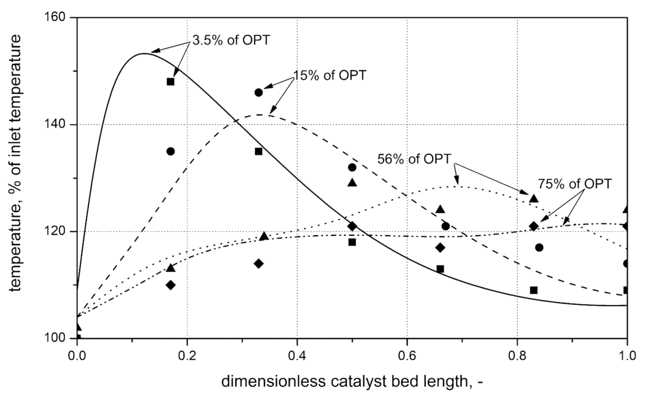
Figure 2 presents the results of simulations of the first stage reactor for hydrogenation of benzene. The results of measurements are presented by points, while the results of calculations are presented by lines. Considering the first of the predicted temperature profiles (solid line), it is easy to observe a higher temperature reaction zone. The reaction zone moves along the reactor with time, while the maximum temperature drops down, which can be connected with catalyst deactivation. The accuracy of calculations is good over the entire catalyst lifetime; however, model precision varies with time. The best results of simulations are observed for fresh catalyst bed, and then precision decreases. This observation suggests that the deviation results mainly from a simple description of the model’s deactivation process, discussed in more detail in [
12]. The results presented there suggest that the deactivation of catalyst is also caused by carbon deposition.
The results show that the estimation of only one model parameter makes the model most valuable. Results are more accurate and, as a consequence, the predictions are the most reliable. However, it should be noted that the choice of model parameters or parameters to estimate should be well thought out. A wrong choice or estimation of too many parameters can be a source of error. The model can even give results without physical meaning. For this reason, the model after estimation should be verified (see also
Figure 1).
The model and the obtained simulation results improved the understanding of the investigated process. They were used to determine the main deactivation factors for the process and unambiguously showed that poisoning by sulfur compounds present in the reactor inlet composition may not be the only reason for dropping the catalyst bed activity. Simulations allow formulating a hypothesis to draw the right direction of experiments. They show that the second main factor of deactivation is carbon deposits formed on the catalyst surface.
Further investigations will concentrate on improving the description of the deactivation process.
3. The Process
The process considered and investigated is the first stage of a caprolactam production process according to the Polish technology named CYCLOPOL. The industrial process was conducted in a heterogeneous multitubular reactor at the temperature in the range of 150–260 °C with a commercial catalyst KUB−3 (manufacturer: New Chemical Syntheses Institute, Pulawy, Poland). The main components of the KUB−3 catalyst are Ni, NiO, and Al2O3. Nickel is the catalyst’s active component, while alumina is a structural promoter that provides the catalyst with high thermal stability.
The hydrogenation of benzene is conducted in two stages. Partial hydrogenation occurs in the first stage, under 0.3 MPa of pressure in a hydrogen shortage. In the second one, benzene is in practice entirely hydrogenated to cyclohexane under pressure (1.0 MPa) and in hydrogen excess. There appears a reaction zone in the catalyst bed, which runs step by step, along the reactor during its regular operation. The zone position change results from catalyst bed deactivation, which is caused by the sorption of sulfur compounds and coke deposition. The full deactivation process of the first catalyst bed takes about 4 years of process operation. The main components of the reaction mixture are cyclohexane, hydrogen, benzene, and nitrogen. Nitrogen is the inert component.
The presented description of the process should help foresee potential problems that can be met in model development.
4. Experiments
The goal of our study was to develop the mathematical model of the first-stage reactor of hydrogenation of benzene. The experimental data necessary to realize this project were obtained by the researchers of New Chemical Synthesis Institute.
An extensive investigation of the benzene hydrogenation process was undertaken by the manufacturer of the catalyst—New Chemical Synthesis Institute. The investigation scheme was quite broad and contained the following.
Measurements of inlet and outlet gas compositions, temperature along the catalyst bed, and determination of the activity of the catalyst bed. These studies were carried out in chemical plants using a commercial reactor over one full action period of the catalyst bed (action period = time between filling and emptying of the reactor). The commercial reactor was of counterflow, multitubular, fixed bed type. It worked under pressure approx. 0.3 MPa, synthesis gas containing approx. Seventy-five percent of hydrogen was used at the reactor inlet. The main process parameters were monitored to prevent undesirable phenomena that could influence productivity (e.g., too small conversion of benzene). Monitoring of process parameters is a standard procedure for commercial technologies. Process data from the plant is an important part of a quality assurance plan. They can be used for model validation. Results are presented in [
12,
13].
Determination of a kinetic equation in a Temkin type reactor [
14]. The reactor was operated in the differential regime. The effects of overall pressure, benzene conversion, and hydrogen/benzene mole ratio were studied. The kinetic rate equation acquired from the studies has a structure:
Equation (3) is proposed by New Chemical Syntheses Institute (Pulawy, Poland) to best fit the experimental results. The form of Equation (3) results from the atypical behavior of the considered process. The reaction rate first grows with temperature, reaches a maximum at about 180 °C, and then decreases. Similar behavior is observed when the ratio of hydrogen to benzene increases. Thus, the atypical behavior and the intention to achieve the best compatibility of the reaction rates anticipated by Equation (3) with real measurements resulted in an atypical form of the kinetic equation. The term “
A” is a constant corresponding to the kinetic rate at 200 °C, under pressure 0.3 MPa, for the conversion of 5% and hydrogen/benzene ratio equal to 3. The other functions are of a polynomial type and should be considered as correction terms concerning temperature, benzene conversion, total pressure, and the ratio of partial pressures of hydrogen and benzene, respectively. Full description of the experiments made and coefficients of polynomials “
f(…)” as well as the equilibrium constants
Kx and
Kp are presented by Stołecki et al. [
13]. The expression (3) should be regarded as an empirical kinetic correlation, which predicts the reaction rate within the range of experimental conditions with very good precision. Finally, we would like to clarify that our attempts to fit Langmuir–Hinshelwood equations were unsuccessful. The coefficients were estimated with significant errors (low correlation coefficient, large confidence intervals) [ibid].
- 3.
Many experiments with a single tube laboratory reactor were conducted on the fresh (not poisoned) catalyst in the range of commercial reactor operating conditions; these investigations’ main goal was to verify the rate equation and a reactor model. The experimental setup was the same as presented in [
13], with one reservation, viz. the catalyst bed was of fixed-bed type.
5. The Final Version of a Reactor Model
In the reactor process, the tubes present four main components of the reaction mixture (hydrogen, benzene, cyclohexane, nitrogen—inert component) and thiophene, i.e., the component that deactivates the catalyst bed; the reaction is very exothermic; and the kinetic equation is non-linear. Since the process is complex and the task of model development could require a great deal of effort, we reached the goal of investigation in these steps. At first, a pseudohomogeneous model (without catalyst particle balance) was tested. The model assumes that concentration and temperature gradients only occur in the axial direction. The only transport mechanism operating in this direction is the overall flow of the plug flow type (according to guidelines given by Froment and Bishoff [
15]). For industrial conditions, the assumptions presented are not often fulfilled. For very rapid reactions with a significant heat effect (as the reaction under consideration), it may be necessary to distinguish between the fluid and catalyst surface conditions. As expected, it turned out to be very inaccurate, but the model equation set was solved very fast and allowed us to gather the necessary experience. Additionally, for special experimental conditions that are relatively easy to achieve in the laboratory, viz. external mass transfer resistance is much larger than the internal one, it is possible to achieve a fast estimation of reaction kinetic parameter values with the inverse method. The possibility of estimating the reaction kinetic model parameters by solving a simple pseudohomogenous model is crucial for all modeling processes because the numerical solution of the pseudohomogenous model is several dozen times faster than a heterogeneous model. A quasi-steady-state heterogeneous model with a simple model of sulfur compounds sorption was also developed. The sorption front moves with a constant velocity along the reactor. This model, in contrast to the last used, considers the interaction between the gas and solid phase in the reactor. Rather unexpectedly, its accuracy was insufficient. Finally, a quasi-steady-state heterogeneous model taking account of the sorption of sulfur compounds described by a differential equation was created according to guidelines presented in [
15]. The mass and heat conservation equations are the application for the mass balance of hydrogen and thiophene as well as for heat balance. The mass balance of other species is described by algebraic equations according to the stoichiometry of the process. The effect of species concentrations on diffusivity was also taken into account in the model. As a result, the precision of the simulations improved.
The final version of the model of the benzene hydrogenation reactor is presented below. The model is described by a differential-algebraic equations set and contains mass balance equations for fluid and pellet (for hydrogen, benzene, cyclohexane, nitrogen, and thiophene) and heat balance equations for fluid and pellet.
The following simplifying assumptions were used for the modeling of the reactor:
operating conditions in any tube of the multitubular commercial reactor are the same;
the reactor time scale is much shorter than the time scale for reactor decay, so a quasi-steady-state approximation is valid;
irreversible sorption of thiophene is the only reason for catalyst decay;
the rate of benzene consumption is described by Equation (3);
average mass and heat transport parameters are used;
average physical properties of components are used (excluding hydrogen diffusion coefficient).
5.1. Mass Balances for Reactor
5.1.1. Hydrogen Mass Balance
initial and boundary conditions:
5.1.2. Other Mass Balances
Given assumption 2, mass balances of other components can be expressed by algebraic expressions:
5.1.3. Thiophene Mass Balance
initial and boundary conditions:
Linear gas velocity is variable and can be calculated from
5.2. Heat Balance for Reactor
The heat balance for the fluid is given by
initial and boundary conditions:
5.3. Mass Balances for Pellet
5.3.1. Hydrogen Mass Balance
initial and boundary conditions:
5.3.2. Mass Balances of Other Components
As recommended by Froment and Bishoff [
9], the hydrogen diffusion coefficient is calculated from
5.3.3. Thiophene Mass Balance
initial and boundary conditions:
5.4. Fouling Kinetics
The equation of sulphur compounds sorption is given by
initial condition
The activity of catalyst is calculated from
5.5. Heat Balance for Pellet
The heat balance for the catalyst pellet is given by
initial and boundary conditions:
5.6. Auxiliary Equations
The equations describing total concentration, conversion, and amount of absorbed com-pounds are as follows
The transport parameters for this model were evaluated using the following expressions:
recommended by Doraiswamy and Sharma [
16]—Equation 6.5
recommended by Doraiswamy and Sharma [
16]—Equation 10.48
recommended by Doraiswamy and Sharma [
16]—Equation 6.9
recommended by Pohorecki and Wroński [
17]—Table A-6
recommended by Doraiswamy and Sharma [
16]— Table 10-5.
Definitions or descriptions of the dimensionless numbers and other parameters included in Equations (45)–(49) are presented in the literature cited.
The presented model was solved by the authors’ program, coded in Delphi. The program solves differential–algebraic equations set and estimates model parameters (the inverse method is applied). Orthogonal collocation on a finite elements method is used for the discretization of spatial terms of partial differential equations. The resulting equation set is solved by the method of lines. The Marquardt algorithm is used for the estimation of the optimal value of the model parameter.
6. Conclusions
The paper presents a way of obtaining a mathematical model of a large-scale, sophisticated industrial process. The resulting reactor model of the hydrogenation of benzene predicts well the results obtained in practice. In the authors’ opinion, the factors involved in a successful result of modeling are as follows:
1. Highly accurate kinetic rate equation. The rate equation was obtained for the considered reactor from the mathematical analysis of process operating data. Its structure can differ from commonly used kinetic equations but must be highly accurate over a limited range restricted to experimental conditions.
2. The proper model structure. The knowledge of these several particulars that decide on successful modeling was obtained gradually and in various ways. The trial versions were created from simple ones towards more complex models. This allowed us to gather the necessary experience, and, as a result, the final version of the model is not too complex—the computer can solve the model equations relatively fast. The additional advantage is a more comfortable choice of the proper algorithm of the solution.
3. Results were verified, and some correlations or parameters were improved using estimation methods. The main aim of improving the correlation used was obtaining as accurate a model as possible. It should be highlighted that the procedure applied above can concern factors included and not included in the model but influencing the real reactor. It is not possible to discount their bad influence completely, but a reduction is possible.
The suggestions formulated above can help develop any complex mathematical model in the chemical engineering field, especially for heterogeneous catalysis, chromatography, adsorption, etc.


