Article

In Situ Generated Nanosized Sulfide Ni-W Catalysts Based on Zeolite for the Hydrocracking of the Pyrolysis Fuel Oil into the BTX Fraction

A.V. Topchiev Institute of Petrochemical Synthesis, Russian Academy of Sciences (TIPS RAS), 119991 Moscow, Russia
*
Author to whom correspondence should be addressed.
Catalysts 2020, 10(10), 1152; https://doi.org/10.3390/catal10101152
Submission received: 9 September 2020 / Revised: 28 September 2020 / Accepted: 1 October 2020 / Published: 7 October 2020
(This article belongs to the Special Issue Heterogeneous Catalysts for Petrochemical Synthesis and Oil Refining)

Abstract

:
The hydrocracking reaction of a pyrolysis fuel oil fraction using in situ generated nano-sized NiWS-sulfide catalysts is studied. The obtained catalysts were defined using X-ray photoelectron spectroscopy (XPS) and transmission electron microscopy (TEM). The features of catalytically active phase generation, as well as its structure and morphology were considered. The catalytic reactivity of in situ generated catalysts was evaluated using the hydrocracking reaction of pyrolysis fuel oil to obtain a light fraction to be used as a feedstock for benzene, toluene, and xylene (BTX) production. It was demonstrated that the temperature of 380 °C, pressure of 5 MPa, and catalyst-to-feedstock ratio of 4% provide for a target fraction (IPB −180 °C) yield of 44 wt %, and the BTX yield of reaching 15 wt %.

1. Introduction

The increasing development of environmentally friendly energy sources and the search for new ones such as the sun, hydrogen, biomass [1] has had a negative impact on the price and global demand for oil and natural gas used for fuel production. This has become a challenge for the oil producing industry since a large group of chemicals can still be obtained from oil and natural gas only. Thus, despite of the intensified studies on the possibility to obtain the benzene, toluene, and xylene (BTX) fraction from alternative sources such as plastic waste as well as bio oil components [2,3,4,5,6], oil resources are still the primary method of BTX fraction recovery [7,8,9]. The demand for aromatic hydrocarbons and BTX fraction as their primary source has been increasing from year to year because of the consistently growing polymers market. The main sources of the BTX fraction today are reforming and the process is mainly known as the “steam cracking.” Benzene, toluene, and xylene (BTX) are widely used as the feedstock for the industrial production of chemicals. In its turn, heavy oil fractions rich in polyaromatic compounds (that originate also from the both catalytic reforming and the naphtha steam cracking) can be used for the BTX production [10,11].
Because of the increasing demand for low molecular weight olefins, the number of steam cracking facilities has increased as well. The annual average growth of ethylene and propylene consumption exceeds 4%. Steam cracking capacity will continue to grow driven by ethylene/propylene demand. This process results in a large number of aromatic compounds and low-value waste in the form of pyrolysis fuel oil (PFO). PFO is used as a component of boiler fuel oil, or for the production of petroleum resins. PFO is not currently being recycled properly. Residual fractions of the pyrolysis process, in particular pyrolysis fuel oil (PFO), can be used for the BTX production. As PFO consists mainly of diaromatic compounds such as naphthalene (35.98%), its ethyl-substituted equivalents of naphthalene (10.95%) and biphenyl (27.97%), it could be considered as a promising feedstock for the hydrocracking process that yields valuable products, such as gasoline or aromatics [12,13]. The hydrocracking of heavy oil residues is the wide-spread method used to lighten the composition of heavy oil residues and obtain a more valuable feedstock [14,15,16,17].
Supported metal catalysts are generally used as hydrocracking catalysts. Molybdenum or tungsten is used as an active metal. The catalysts are active in their sulfide form, with nickel or cobalt used as promoting substances. Acid materials such as zeolites, other aluminosilicates, or aluminum oxide are used as support [18,19,20,21,22]. Some studies describe the influence of oxide substrates on hydrogenation, hydrodesulfuration, and hydrocracking, stating that aluminum oxide-supported systems have a higher reactivity during hydrogenation [23,24,25]. Publications describe successful examples of the recovery of a commercially valuable BTX fraction from light catalytic gas oil (LCGO) on supported NiMo/Al2O3 catalysts, with a BTX fraction yield of 44 to 70 wt % [26]. In this case, the average yield of the BTX fraction varies from 15% to 50% when obtained through pyrolysis [2,6], and from 20% to 50% when obtained through hydrocracking [9,27].
Unsupported sulfide catalysts have been gaining popularity recently during studies of hydroprocessing in oil refining. This is due to their high catalytic reactivity as compared to supported hydrotreating catalysts [28,29], as well as their ability to offer a solution for the active center’s deactivation problem caused by the deposition of coke and condensation products [30,31].
Unsupported sulfide catalysts on the basis of transition metals can be obtained using different methods: coacervation [32], codeposition [33], or precursor decomposition [34,35,36]. Precursors can include water-soluble [34,35] and oil-soluble [36] transition metal compounds. Despite the fact that the use of water-soluble compounds is more cost effective because of their low cost, they entail the formation of somewhat larger particles, which reduces the reactivity of the obtained catalyst [37]. Dispersed Ni (Co) –W (Mo) –S sulfide catalysts synthesized through in situ decomposition of various precursors are stable and characterized by high dispersiveness and a highly developed external surface [38].
Comparison of the reactivity of MoS2 and WS2 sulfide catalysts generated in situ from oil-soluble precursors during the hydrocracking of heavy residues has demonstrated the advantage of tungsten catalysts over molybdenum ones. WS2 was more dispersive and demonstrated a higher hydrogenating reactivity as compared to the molybdenum equivalent [39].
As was established previously, the Ni–W–S catalyst exhibits reactivity in the course of coking resin hydrogenation. The optimal temperature of the pyrolysis oil hydrotreatment is 380 °C. It provides for the minimum amount of bicyclic and polycyclic aromatic hydrocarbons, and ensures no thermal cracking process. [40].
Previously, the hydrocracking of hydrocarbon fractions in the presence of the in situ generated catalysts was described in the works [41,42,43,44,45]. However, to the best of our knowledge, there are no precedents for the use of a bifunctional nanoheterogeneous catalytic system to obtain the BTX fraction from the pyrolysis fuel oil.
In continuation of work on the study of the regularities of hydrogenation of aromatized hydrocarbon fractions in the presence of nanosized in situ formed sulfide catalysts [35,46].
We offer a fundamentally new design opportunity for a quasi-homogeneous bifunctional catalytic system that can solve the problem of obtaining BTX from a pyrolysis fuel oil.
This study demonstrates the possibility of the use of the unsupported NiWS-HY catalysts generated in situ in the hydrocarbon feedstock from such oil-soluble precursors as tungsten hexacarbonyl (W(CO)6) and Nickel(II)2-ethylhexanoate (Ni(C7H15COO)2) with HY zeolite addition for the selective recovery of the BTX fraction from pyrolysis fuel oil.

2. Results

2.1. Catalytic Properties

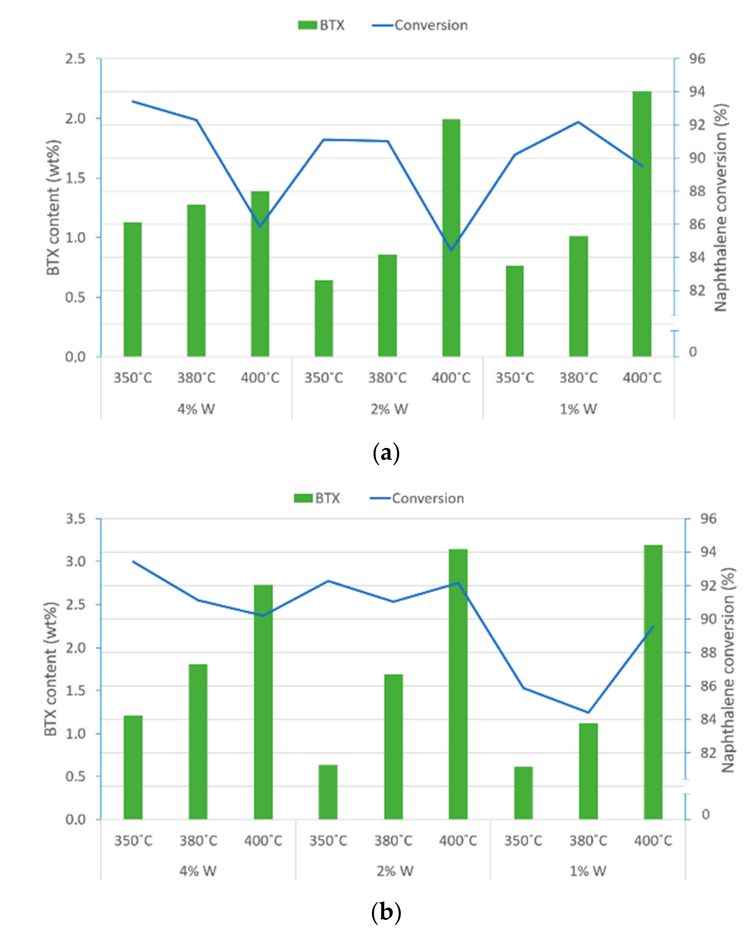
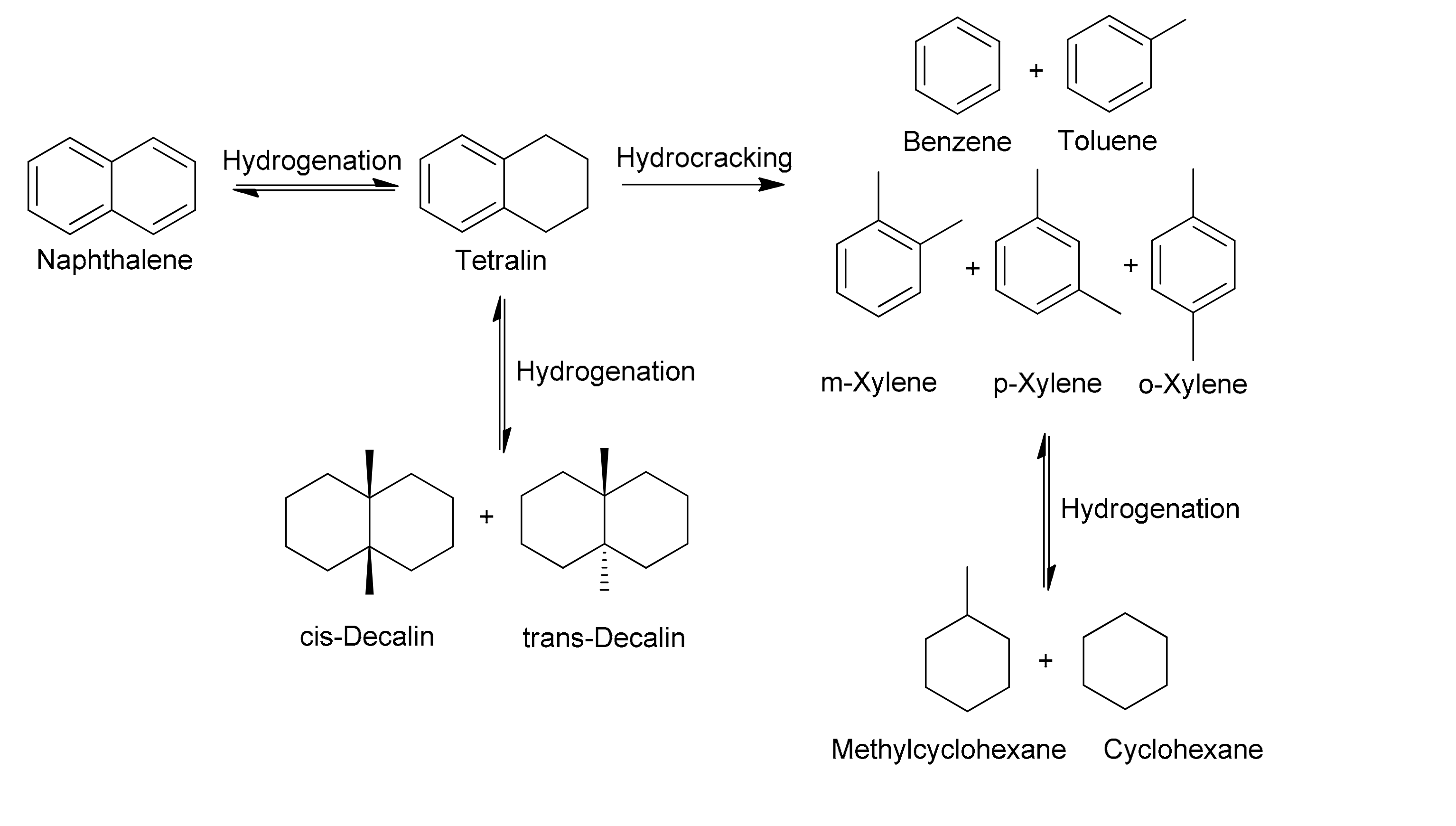
2.1.1. Naphthalene Hydrocracking with NiWS-HY Catalysts

The reactivity of in situ generated catalysts as well as the possibility of the BTX fraction selective recovery were studied by the example of a model feedstock, for which purpose 10% solution of naphthalene in hexadecane was chosen as the feed mixture. The study was carried out in an autoclave-type batch reactor at P = 5 MPa, t = 5 h, and W:Ni ratio = 1:2. With a view to identifying the influence of temperature on product composition and conversion, experiments on in situ generated NiWS-HY catalyst were conducted at 350 °C, 380 °C, and 400 °C by varying the zeolite content at a level of 0.5 wt % and 1 wt %, and tungsten content at a level of 1 wt %, 2 wt %, and 4 wt %. Blank test showed that hexadecane does not react in these conditions.
The conversion of naphthalene under the selected conditions (Figure 1) was high and reached 84%–93%.Temperature increase up to 400 °C resulted in 5 to 10% lower naphthalene conversion, which could be due to the specifics of Ni-W-S hydrogenating phase formation on the zeolite surface [47]. It should be as well noted, that the decrease in the conversion of naphthalene with increasing temperature does not contradict the thermodynamic laws of the hydrogenation reaction of this compound.
It can be seen from the graph of Figure 1 that the highest conversion is achieved on the average at 380 °C and a tungsten content of 4 wt % [46]. No significant changes in naphthalene conversion versus NiWS-HY(0.5%) or NiWS-HY(1%) zeolite content were revealed.
The sum of the benzene, toluene, and xylenes recovered during the hydrocracking process is about 2 to 3.5%. The highest BTX yield were obtained at 400 °C and a weight content of 1% for zeolite and 4% for tungsten (Figure 2). Under these conditions, in a mixture of xylenes, the ratio m-xylene:p-xylene = 1:10, and o-xylene is formed in trace amounts. We used these results to identify the dependencies of BTX components of selectivity on temperature and tungsten content (Figure 2). As a result, the highest benzene content as compared to xylene and toluene is observed.
At the same time, the main products of naphthalene hydrocracking under these conditions are tetralin and decalin. The higher their temperature, the lower their content in the reaction products, and the higher the BTX fraction content. The reaction is probably of consecutive behavior, with the tetralin acting as an intermediate. Scheme 1. If the hydrogenation rate is higher than the tetralin cracking rate, tetralin is accumulated and then hydrogenated to yield decalins. In a different scenario, tetralin is not generated at all [9,27].
Considering the hydrocracking results for a model mixture and preceding experience of the colleagues, the best hydrocracking results for the PFO fraction are expected when NiWS-HY(1%) is used since a high degree of feedstock conversion can probably be achieved when 1 wt % of zeolite is added [48], at 380 °C to 400 °C, and a tungsten content of 4% (Table 1).

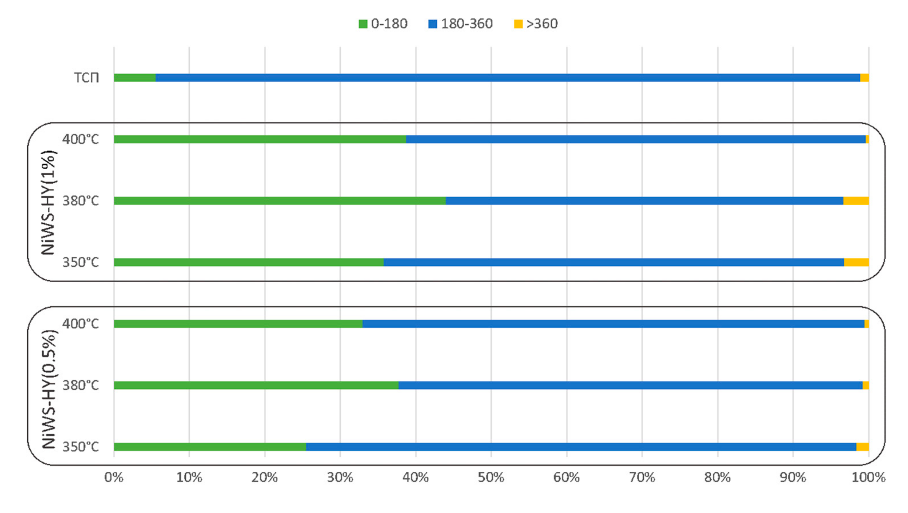
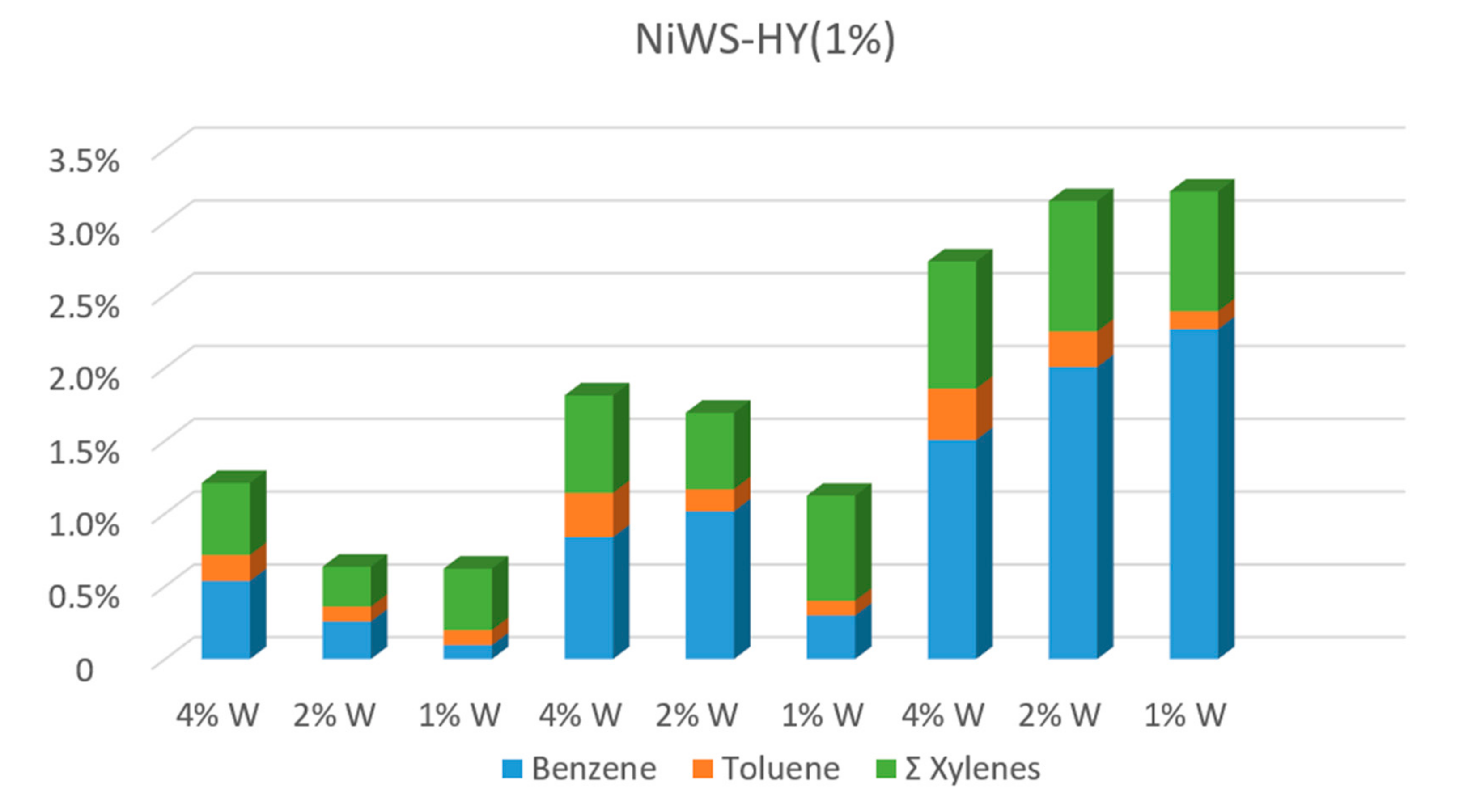
2.1.2. Pyrolysis Fuel Oil Hydrocracking with NiWS-HY Catalysts

The reactivity of in situ generated NiWS-HY(0.5%) and NiWS-HY(1%) catalysts during pyrolysis fuel oil hydroconversion was studied in an autoclave-type batch reactor at standard conditions p = 5 MPa, t = 5 h, and ratio W:Ni = 1:2, initial hydrogen pressure in the reaction system of 5.0 MPa, with intensive stirring. An HPR fraction with an upper boiling point of 330 °C, whose characteristics are given in Materials and Methods section, was used as a starting material.
To determine the optimal process temperature, we compared the active NiWS-HY(1%) and NiWS-HY (0.5%) catalysts with constant mass content W = 4%. Table 2 shows the BTX (benzene, toluene, xylene) selectivity between the reaction temperature and zeolite weight percentage. It was demonstrated that the in situ generated NiWS-HY(1%) catalyst is more active in the hydrocracking reaction than NiWS-HY (0.5%). The best selectivity of the BTX fraction was obtained at 380 °C. Maximum selectivity of BTX reaches 15 wt %.
When comparing the amount of the light fraction (with a boiling temperature up to 180 °C) generated at a different zeolite content, the predictably better results were obtained at a higher zeolite content (1 wt %) (Figure 3) [49]. The resulting light fraction also contains other valuable compounds.
It is also noteworthy that PFO hydrocracking yields were 8–10 wt % in the reaction mass of cyclohexane as one of the benzene hydrogenation products. The cyclohexane is a non-toxic intermediate compound, which is widely used for the production of nylons and caprolactam. Currently, the greatest part of the world’s cyclohexane production is based on benzene hydrogenation [50].
If we consider the dependence of the component composition of BTX reaction products (Table 3) on the cat/raw material ratio, we can note that the selectivity of benzene formation in the mixture increases with an increasing of wt % of tungsten, while selectivity of xylenes formation, on the contrary, increases with a decreasing of the amount of tungsten.
The fractional composition of TSP after hydrocracking changes noticeably, the amount of the fraction with boiling points of 0–180 °C increases almost ten times, and it contains about 15 wt % of valuable components of BTX fraction (benzene-toluene-xylenes). The fraction with boiling points of 180–360 °C contains more than 30 wt % of decalins and tetralin.

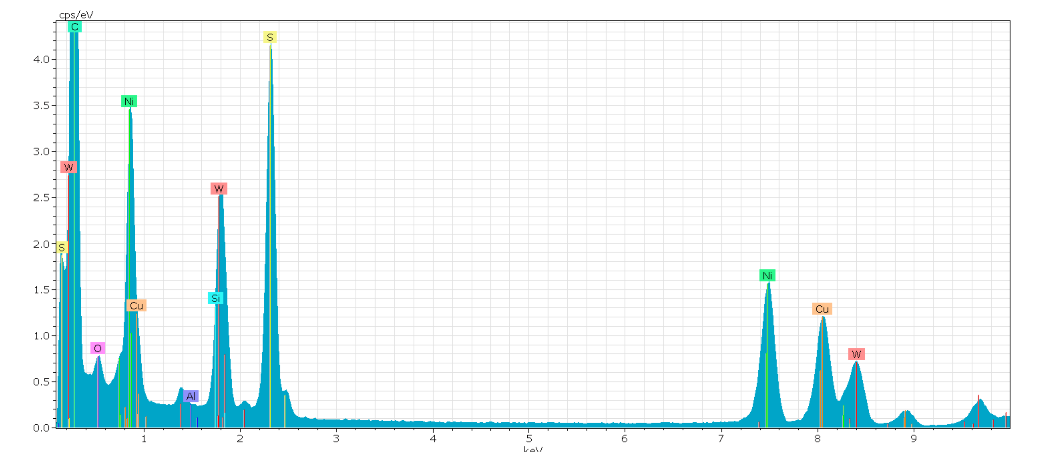
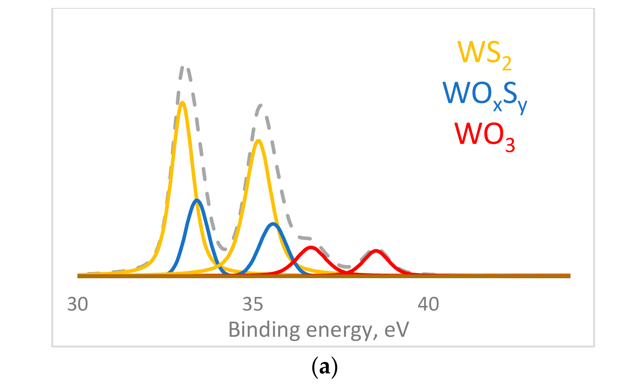
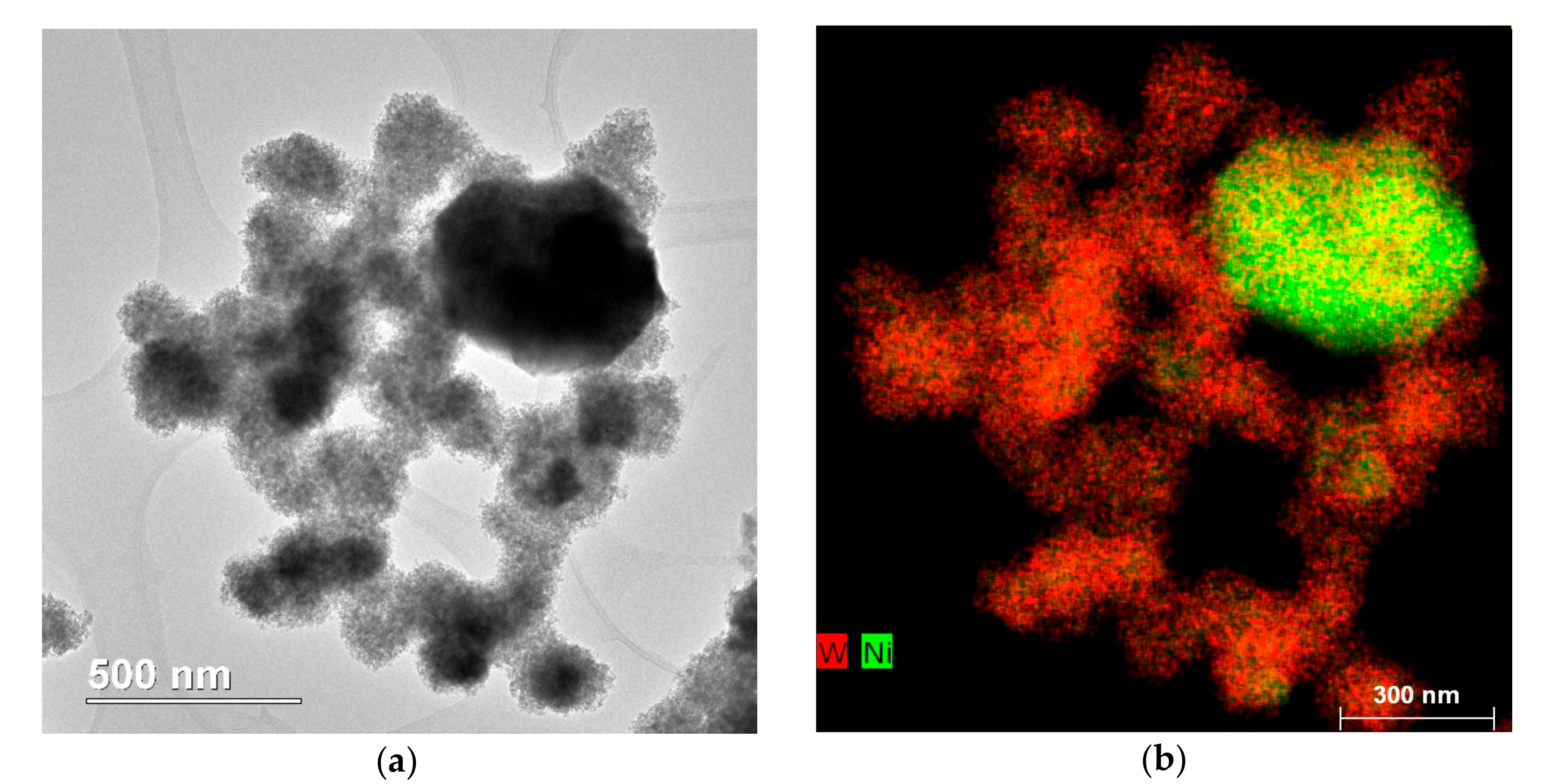
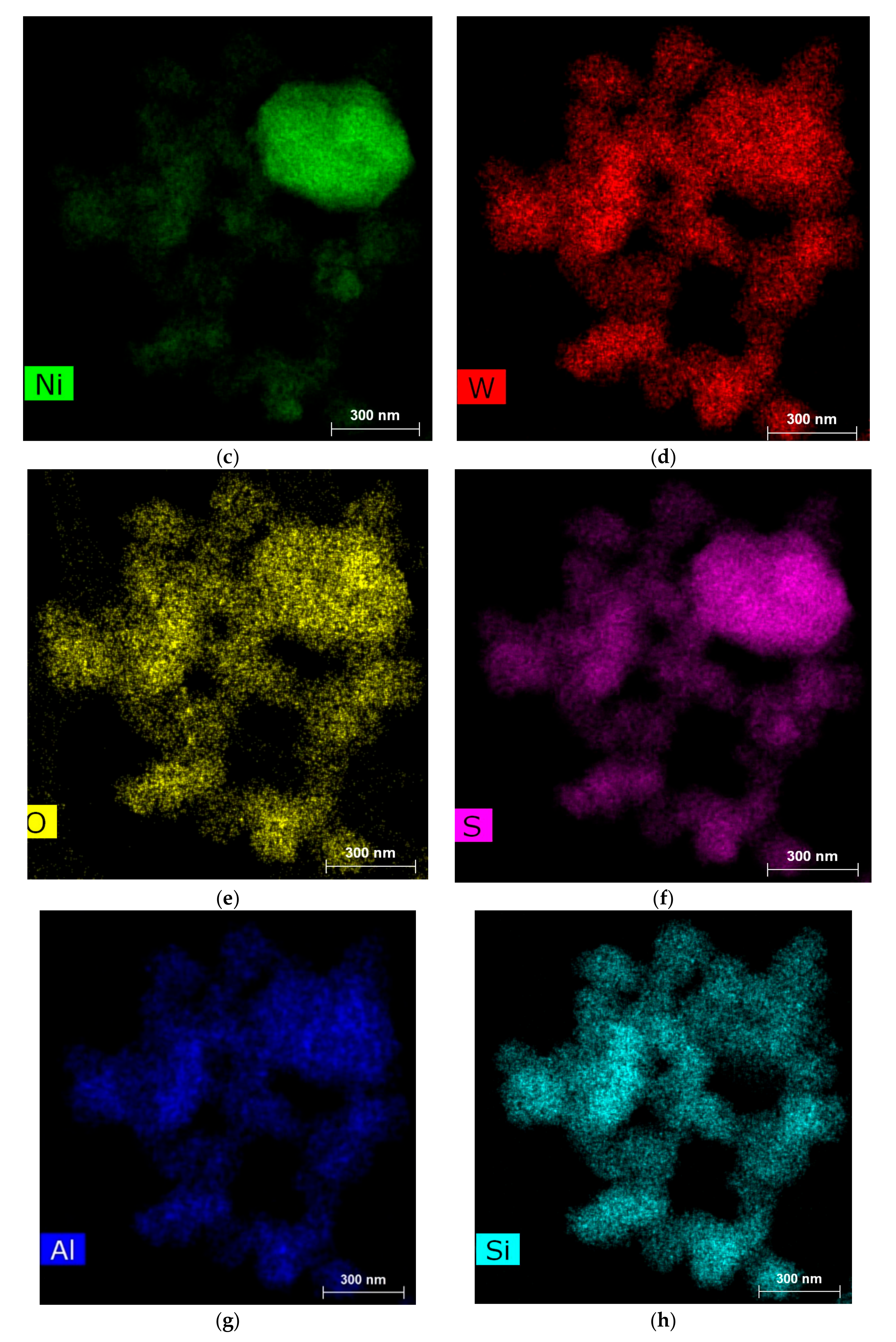
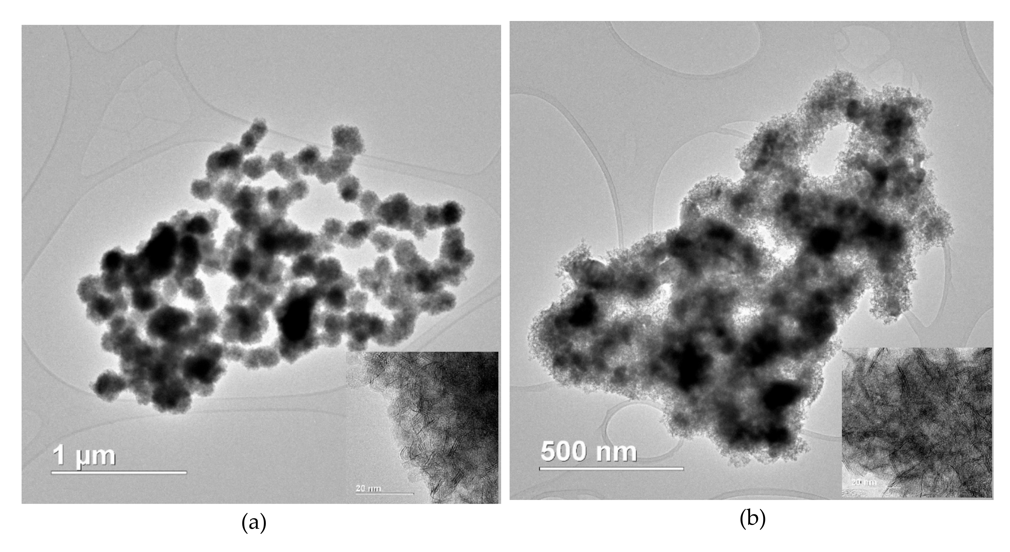
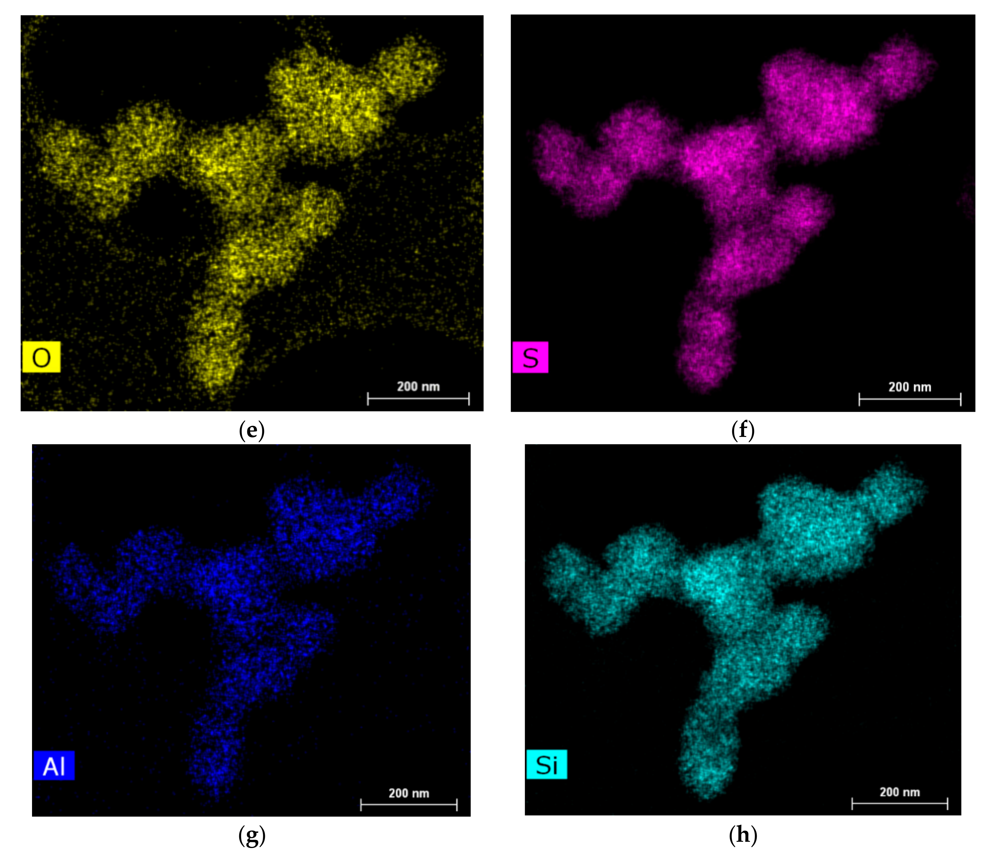
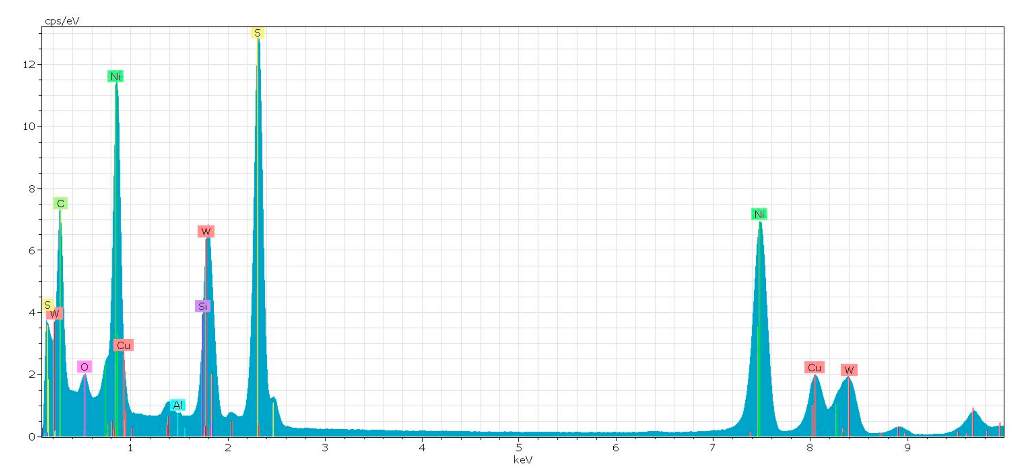
2.2. Catalyst Properties

As is known, the activity of supported sulfide catalysts depends on the degree of sulfidation of the catalyst and the promoter/nickel ratio. The degree of sulfidation also depends on the temperature. The phases of nickel sulfide (NiS) and oxosulfide tungsten (WOxSy) are formed on a support structure at 300–400 °C. The higher the degree of interaction with the support, the more difficult the sulfidation of the oxysulfide phase and the formation of a mixed Ni-W-S phase are [49].
Based on the results of XPS, we revealed some dependences of the formed catalyst. We analyzed two catalysts obtained in situ in real raw material (pyrolysis fuel oil) at different zeolite/raw material ratios (0.5% and 1%) with catalyst sulfurization with elemental sulfur in the reaction medium (Table 4 and Table 5). The best results for the selectivity of BTX fraction were showed with a tungsten content of 4 wt % at standard conditions (p = 5 MPa, t = 5 h, and W: Ni ratio = 1:2). The results of XPS obtained by us are consistent with the literature [51] since the signals of oxygen, carbon, sulfur, nickel, and tungsten correspond to characteristic signals of nickel-tungsten-sulfide catalysts. Promotion coefficient of NiWS-HY (0.5%) catalyst is 0.34, and promotion coefficient of NiWS-HY (1%) catalyst is only 0.19, Figure 4.
Based on the XPS results, it can be concluded that the active Ni-W-S phase is more easily formed on zeolite surface at mass content of 0.5%, which is reflected in the results of the catalytic experiment, and also in a larger amount of WS2. It is also known to contribute to the hydrogenation process. But its activity is much lower than that of the phase Ni-W-S [52].
In an attempt to explain the experimental data on the activity of catalysts in hydrocracking, we studied the morphology of in situ formed catalysts isolated after the reaction using transmission electron microscopy (TEM). It should be noted that, according to TEM data, catalysts prepared in situ with the addition of zeolites directly to the reaction medium are spherical agglomerates (Figure 5). Moreover, in a sample with a lower zeolite content, the spherical shape is more pronounced, the average size of a spherical particle is from 0.18 to 0.2 μm, and in a catalyst sample with a high zeolite content, the average size of spherical particles is from 0.2 to 0.24 μm. The number of layers in sulfide packs (N) and the length of the stack (L) were determined manually. For the sample obtained with the addition of 0.5 wt % of zeolite, average N = 4.7, and L = 3.3, while obtained with the addition of 1 wt % of zeolite, N = 2.8, L = 6.2. We calculated the dispersion of particles (Ni-WS2) according to the published method [51]. The dispersion of NiWS-HY (0.5%) catalyst 0.23 and NiWS-HY (1%) catalyst 0.2 was calculated.
The size distribution of crystals of Ni-W, NiSx, etc., larger than 5 nm can be determined by analyzing the images of element maps. These element maps confirm the results of XPS and indicate that a larger amount of the hydrogenating Ni-W-S phase is formed under the condition of a smaller addition (0.5 wt %) of zeolite to the reaction medium. Thus, in this case, the results indicate the fact that the concentration of zeolite present in the mixture has a significant effect on the formation of the active phase.
Ni sulfide (NiSx) crystals are visible on TEM images and element maps of STEM-EDX and NiWS-HY (0.5%) (Figure 6 and NiWS-HY (1%) (Figure 7) hydrocracking catalysts. Particles range from about 5 to over 100 nm in diameter, all of them are surrounded with a Ni-W-S phase. As is known from the literature, a large amount of crystalline nickel sulfide does not contribute significantly to the hydrogenation process [53]. The distribution maps added to the article Appendix A (Figure A1 and Figure A2).

3. Materials and Methods

3.1. Materials

Reagents used are tungsten hexacarbonyl W(CO)6 (99.99%, Aldrich), nickel(II 2-ethylhexanoate Ni(C7H15COO)2 (78% solution in 2-ethylhexanoic acid, Aldrich). A solution of naphthalene (99%, Aldrich) in hexadecane (≥99%, Aldrich) was used as a substrate.
The fraction of the pyrolysis fuel oil was obtained from the pyrolysis fuel oil produced by Sibur-Kstovo (Kstovo, Russia) by vacuum distillation with the selection of IBP 170 °C fraction (residual distillation pressure-2 Torr). The output of the distillate fraction was 75.4 wt %, the boiling point reduced to atmospheric pressure was 330 °C. The composition shown in Figure 5 contains naphthalene (35.98%), its methyl-substituted analogs (10.95%), and biphenyl (27.97%) (Figure 8).
The mass chromatogram of the fraction was obtained on a Finnigan MAT 95 XL instrument (Varian VF-5 ms capillary column, length of 30 m, inner diameter of 0.25 mm, film thickness of 0.25 µm).
All chemicals were used without preliminary purification.

3.2. Catalyst Synthesis

Sulfide catalysts of the NiWS-HY composition were prepared in situ in a hydrocarbon raw material. Low-soluble salts of hexacarbonyl tungsten W(CO)6 and nickel(II)2-ethylhexanoate Ni(C7H15COO)2 were used as precursors. To form the hydrogenating component of the catalyst in the form of tungsten sulfide promoted with nickel, 2.5 wt. % of elemental sulfur was added to the reaction mixture as a sulfiding agent. As the acidic component of the catalyst, a commercial wide-pore zeolite Y(CBV 600) with a three-dimensional porous structure and a channel diameter of 7.4 Å and cavities of 12 Å was chosen, which was added directly to the reaction medium. In zeolite molar ratio SiO2 / Al2O3 = 5.2. According to TEM data particle size is 400–800 nm. Specific surface area found by the low-temperature adsorption of nitrogen is 530 m2/g. Total concentration of acid sites according to TPD of ammonia is 532 μmol/g [47]. The influence of the content of active metal and zeolite on the catalytic activity and selectivity of BTX production and the formation of the catalyst was also studied.
The structure and morphology of the catalysts obtained in situ were investigated by transmission electron microscopy (TEM) (JEOL, Tokyo, Japan), FEI Tecnai Osiris TEM at an accelerating voltage of 200 keV. For transmission electron microscopy (TEM), a FEI Tecnai Osiris TEM with an accelerating voltage of 200 keV was used.
To measure the (Ni)WS2 dispersion, the average fraction of W atoms at the (Ni)WS2 edge surface was calculated, assuming that the sulfide slabs were perfect hexagons [47,53]. The presence of a certain number of nickel atoms is not considered. Dispersion (D) was statistically evaluated by dividing the total number of W atoms at the edge surface (We), including corner sites (Wc), by the total number of W atoms (WT) using the slab sizes measured in the TEM micrographs:
D   =   W e + W c W T
  W e   =   6 × n i 12 × N ¯
W c   =   6 ×   N ¯
W T   =   3 × n i 2   3 × n i + 1
where ni is the number of W atoms along one side of the (Ni)WS2 slab, as determined by its average length L ¯ .
L ¯   =   l i n
where li is a length of each slab.
n i   =   10   ×   L ¯ ¯ 3.2 + 1 2
and
N ¯   =   n i N i n ,  
where N ¯ in the average stacking degree and n i is the number of stacks in N i layers.
The XPS analysis of catalysts was performed by ESCALAB MK2 electronic spectrometer (Vacuum Generators LTD) (Physical Electronics, Chanhassen, MN, USA). The samples were studied without heating and ion-beam treatment. The position of the lines of the elements was normalized to the position of C 1s carbon line of the hydrocarbon contamination of the surface. The survey spectrum was measured at an analyzer bandwidth of 50 eV and a scanning interval of 0.25 eV; the particular spectra of the elements were measured at a bandwidth of 20 eV and a scanning interval of 0.2 eV. Deconvolution of the spectra was conducted by non-linear least-square method using the Gaussian-Lorentzian function.
The absolute content of the Ni-W-S phase on the catalyst surface (CNiWS) was calculated using the formula:
  C NiWS   =   NiWS * C Ni 100
where [NiWS] is the relative Ni content in the Ni-W-S phase, %; CNi is the content of Ni atoms on the catalyst surface determined by the XPS method, at. %.
The absolute content of the WS2 phase on the catalyst surface (CWS2) was calculated from the formula:
C WS 2   =   WS 2 * C W 100
where [WS2] is the relative W content in the WS2 phase, %; CW is the content of W atoms on the catalyst surface determined by the XPS method, at. %.
The promoter ratio in the active phase slab was determined:
N i W s l a b   =   C N i W S C W S 2

3.3. Catalytic Tests

A number of experiments were carried out, first at a model mixture, to determine the best conditions for hydrocracking, and then at a fraction of pyrolysis fuel oil (PFO). A 10% solution of naphthalene in hexadecane was chosen as a model mixture. Hydrocracking was carried out in an autoclave-type batch reactor (Stainless steel high-pressure batch reactor). A sample of the catalyst (precursors W (CO)6, Ni(C7H15COO)2 and zeolite HY) was placed in it. The absence of the external diffusion limitations was checked in a separate test.
The sulfiding of the catalysts was carried out directly in the reaction medium by adding elemental sulfur in an amount of 2.5 wt. % in terms of raw materials. Then, the autoclave was sealed and filled with hydrogen to a pressure of 5.0 MPa, the reaction duration was 5 h. We varied the process temperature (350–400 °C), zeolite cont (0.5 and 1 wt %) and W (1–4 wt %) in the reaction medium, the ratio Ni/W = 2:1. The tungsten content in the raw material was calculated using the following formula:
W   =   m ( W CO 6 ) M W M W CO 6 m c ы p ь я × 10 6 p p m
where m(W(CO)6) is the mass of tungsten hexacarbonyl dissolved in the hydrocarbon raw material, g; M (W) is molar mass of tungsten, 183.8 g/mol; M(W(CO)6) is molar mass of tungsten hexacarbonyl, 351.9 g/mol; m (raw material) is the mass of hydrocarbon raw material, g.
The start time of the experiment was considered the moment when the required reaction temperature was established. Upon completion of the reaction, the autoclave was cooled to room temperature and depressurized. The catalyst was separated from the products by centrifugation, and the liquid reaction products were analyzed by gas-liquid chromatography method.

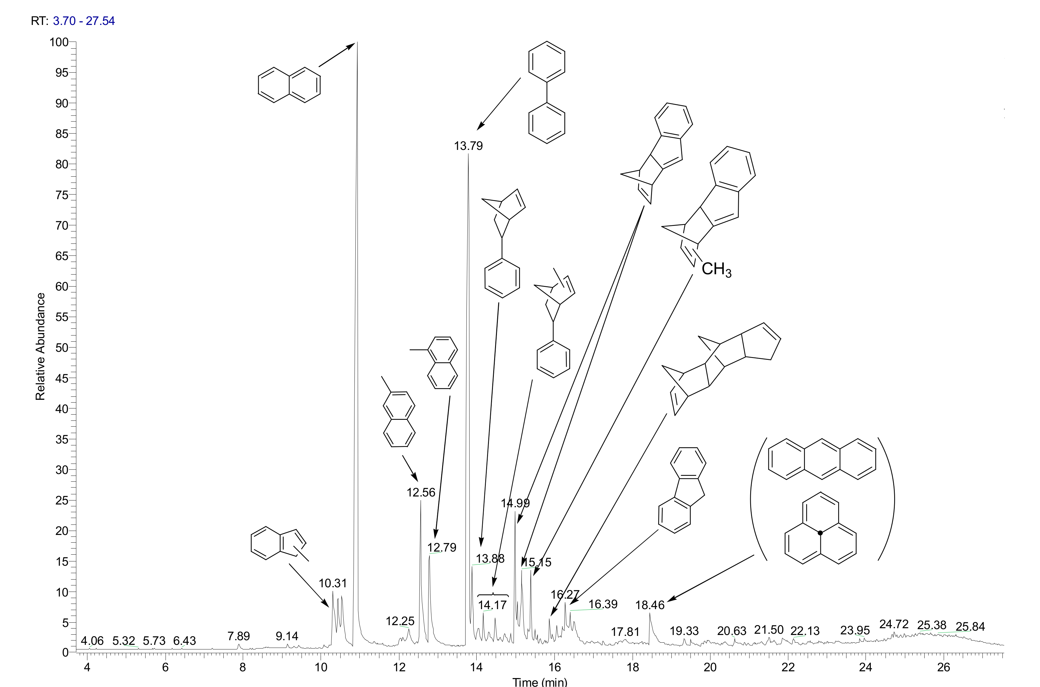
3.4. Products Characterization

Qualitative analysis of liquid products was carried out using Agilent 6890 gas-liquid chromatograph with Finnigan MAT 95 XL mass spectrometric detector (Thermo Scientific) (Supelco, Bellefonte, PA, USA), Varian VF-5MS capillary column (30 m × 0.25 mm × 0.25 μm), with helium as carrier gas. The quantitative and fractional composition of liquid products (gasoline fraction < 180 °C, diesel fraction 180–360 °C, residual fraction > 360 °C) was determined by simulated distillation using a Kristallux 4000 M gas-liquid chromatograph with a flame ionization detector, capillary column SPB-1 (30 m × 0.25 mm × 0.25 μm) (Meta-Khrom, Yoshkar-Ola, Russia) with helium as carrier gas.
The naphthalene conversion (conversion, %) was calculated as the degree of conversion of the initial aromatic compound into hydrocracking products.

4. Conclusions

In this paper, hydrocracking of a pyrolysis fuel oil in a slurry reactor on in situ synthesized NiWS-HY catalysts from low-soluble precursors for the selective production of the BTX fraction was studied for the first time. The qualitative and quantitative composition of the hydrocracking products was studied. It was found that the yield of benzene-toluene-xylenes can reach up to 15% of the total mass of the products. An increase was also noted for the proportion of light products of hydrocracking.
Thus, we can conclude that NiWS-HY catalyst can be considered as a catalyst for the hydrocracking of pyrolysis fuel oil. Moreover, varying the process conditions led to a change in the selectivity for the products of BTX fraction.
The optimal conditions for the process of obtaining BTX fraction from pyrolysis fuel oil were determined. At 380 °C, with 4 wt % of tungsten, and 1 wt % and 0.5 wt % of zeolite, the amount of the product was much greater. The best result was obtained at 380 °C, with 4 wt % of tungsten, and 1 wt % of zeolite, where mass of BTX fraction was about 15%.
The catalyst obtained under these conditions was characterized by XPS method; it was found that with a lower content of zeolite more of the hydrogenating Ni-W-S phase was formed. This is also confirmed by the TEM results.

Author Contributions

Conceptualization, T.K., M.K., V.S., and A.M.; methodology, M.K.; investigation, T.K.; data curation, T.K.; writing—original draft preparation, T.K.; writing—review and editing, A.M. and V.S.; supervision, A.M.; project administration, A.M. All authors have read and agreed to the published version of the manuscript.

Funding

This research received no external funding.

Acknowledgments

This work was carried out within the State Program of TIPS RAS.

Conflicts of Interest

The authors declare no conflict of interest.

Appendix A

Figure A1. EDX spectrum of catalyst NiWS-HY (0.5%).
Catalysts 10 01152 g0a1
Figure A2. EDX spectrum of catalyst NiWS-HY (1%).
Catalysts 10 01152 g0a2

References

  1. Yan, J.D. Biomass to energy in china: Development status and strategic consideration. Chem. Ind. For. Prod. 2014, 34, 151–158. [Google Scholar]
  2. Cho, M.H.; Jung, S.H.; Kim, J.S. Pyrolysis of mixed plastic wastes for the recovery of benzene, toluene, and xylene (BTX) aromatics in a fluidized bed and chlorine removal by applying various additives. Energy Fuels 2010, 24, 1389–1395. [Google Scholar] [CrossRef]
  3. Xu, X.W.; Jiang, E.C. “BTX” from guaiacol HDO under atmospheric pressure: The effect of support and the carbon deposition. Energy Fuels 2017, 31, 2855–2864. [Google Scholar] [CrossRef]
  4. Xu, N.; Pan, D.; Wu, Y.; Xu, S.; Gao, L.; Zhang, J.; Xiao, G. Preparation of nano-sized HZSM-5 zeolite with sodium alginate for glycerol aromatization. React. Kinet. Mech. Catal. 2019, 127, 449–467. [Google Scholar] [CrossRef]
  5. Song, W.; Zhou, S.; Hu, S.; Lai, W.; Lian, Y.; Wang, J.; Jiang, X. Surface engineering of CoMoS nano-sulfide for hydrodeoxygenation of lignin-derived phenols to arenes. ACS Catal. 2019, 9, 259–268. [Google Scholar] [CrossRef]
  6. Jung, S.H.; Cho, M.H.; Kang, B.S.; Kim, J.S. Pyrolysis of a fraction of waste polypropylene and polyethylene for the recovery of BTX aromatics using a fluidized bed reactor. Fuel Process. Technol. 2010, 91, 277–284. [Google Scholar] [CrossRef]
  7. Xu, X.W.; Jiang, E.C.; Li, Z.Y.; Sun, Y. BTX from anisole by hydrodeoxygenation and transalkylation at ambient pressure with zeolite catalysts. Fuel 2018, 221, 440–446. [Google Scholar] [CrossRef]
  8. Tamiyakul, S.; Ubolcharoen, W.; Tungasmita, D.N.; Jongpatiwut, S. Conversion of glycerol to aromatic hydrocarbons over Zn-promoted HZSM-5 catalysts. Catal. Today 2015, 256, 325–335. [Google Scholar] [CrossRef]
  9. Laredo, G.C.; Pérez-Romo, P.; Escobar, J.; Garcia-Gutierrez, J.L.; Vega-Merino, P.M. Light cycle oil upgrading to benzene, toluene, and xylenes by hydrocracking: Studies using model mixtures. Ind. Eng. Chem. Res. 2017, 56, 10939–10948. [Google Scholar] [CrossRef]
  10. Polliotto, V.; Livraghi, S.; Agnoli, S.; Granozzi, G.; Giamello, E. Reversible adsorption of oxygen as superoxide ion on cerium doped zirconium titanate. Appl. Catal. A Gen. 2019, 580, 140–148. [Google Scholar] [CrossRef]
  11. Choi, Y.; Lee, J.; Shin, J.; Lee, S.; Kim, D.; Lee, J.K. Selective hydroconversion of naphthalenes into light alkyl-aromatic hydrocarbons. Appl. Catal. A Gen. 2015, 492, 140–150. [Google Scholar] [CrossRef]
  12. Kim, Y.-S.; Cho, K.-S.; Lee, Y.-K. Structure and activity of Ni2P/desilicated zeolite β catalysts for hydrocracking of pyrolysis fuel oil into benzene, toluene, and xylene. Catalyst 2020, 10, 47. [Google Scholar] [CrossRef] [Green Version]
  13. Upare, D.P.; Park, S.; Kim, M.S.; Jeon, Y.-P.; Kim, J.; Lee, D.; Lee, C.W. Selective hydrocracking of pyrolysis fuel oil into benzene, toluene and xylene over CoMo/beta zeolite catalyst. J. Ind. Eng. Chem. 2017, 46, 356–363. [Google Scholar] [CrossRef]
  14. Sato, K.; Iwata, Y.; Miki, Y.; Shimad, H. Hydrocracking of TEtralin over NiW/USY zeolite catalysts: For the improvement of heavy-oil upgrading catalysts. J. Catal. 1999, 186, 45–56. [Google Scholar] [CrossRef]
  15. Ishihara, A.; Itoh, T.; Nasu, H.; Hashimoto, T.; Doi, T. Hydrocracking of 1-methylnaphthalene/decahydronaphthalene mixture catalyzed by zeolite-alumina composite supported NiMo catalysts. Fuel Process. Technol. 2013, 116, 222–227. [Google Scholar] [CrossRef]
  16. Park, J.I.; Lee, J.K.; Miyawaki, J.; Kim, Y.K.; Yoon, S.H.; Mochida, I. Hydro-conversion of 1-methyl naphthalene into (alkyl)benzenes over alumina-coated USY zeolite-supported NiMoS catalysts. Fuel 2011, 90, 182–189. [Google Scholar] [CrossRef]
  17. Ali, M.A.; Tatsumi, T.; Masuda, T. Development of heavy oil hydrocracking catalysts using amorphous silica-alumina and zeolites as catalyst supports. Appl. Cataly. A Gen. 2002, 233, 77–90. [Google Scholar] [CrossRef]
  18. Silva-Rodrigo, R.; Calderón-Salas, C.; Melo-Banda, J.A.; Domínguez, J.M.; Vázquez-Rodríguez, A. Synthesis, characterization and comparison of catalytic properties of NiMo- and NiW/Ti-MCM-41 catalysts for HDS of thiophene and HVGO. Catal. Today 2004, 98, 123–129. [Google Scholar] [CrossRef]
  19. Leyva, C.; Rana, M.S.; Trejo, F.; Ancheyta, J. On the use of acid-base-supported catalysts for hydroprocessing of heavy petroleum. Ind. Eng. Chem. Res. 2007, 46, 7448–7466. [Google Scholar] [CrossRef]
  20. Leyva, C.; Rana, M.S.; Trejo, F.; Ancheyta, J. NiMo supported acidic catalysts for heavy oil hydroprocessing. Catal. Today 2009, 141, 168–175. [Google Scholar] [CrossRef]
  21. Tiwari, R.; Rana, B.S.; Kumar, R.; Verma, D.; Kumar, R.; Joshi, R.K.; Garg, M.O.; Sinha, A.K. Hydrotreating and hydrocracking catalysts for processing of waste soya-oil and refinery-oil mixtures. Catal. Commun. 2011, 12, 559–562. [Google Scholar] [CrossRef]
  22. Looi, P.Y.; Mohamed, A.R.; Tye, C.T. Hydrocracking of residual oil using molybdenum supported over mesoporous alumina as a catalyst. Chem. Eng. J. 2012, 181, 717–724. [Google Scholar] [CrossRef]
  23. Nishijima, A.; Shimada, H.; Sato, T.; Yoshimur, Y.; Hiraishi, J. Support effects on hydrocarcking and hydrogenation activities of molybdenum catlysts used for upgrading coal-derived liquids. Polyhedron 1986, 5, 243–247. [Google Scholar] [CrossRef]
  24. Shimada, H. Morphology, dispersion and catalytic functions of supported molybdenum sulfide catalysts for hydrotreating petroleum fractions. J. Jpn. Pet. Inst. 2016, 59, 46–58. [Google Scholar] [CrossRef] [Green Version]
  25. Castillo-Villalón, P.; Ramírez, J.; Cuevas, R.; Vázquez, P.; Castañeda, R. Influence of the support on the catalytic performance of Mo, CoMo, and NiMo catalysts supported on Al2O3 and TiO2 during the HDS of thiophene, dibenzothiophene, or 4,6-dimethyldibenzothiophene. Catal. Today 2016, 259, 140–149. [Google Scholar] [CrossRef]
  26. Laredo, G.C.; Pérez-Romo, P.; Vega-Merino, P.M.; Arzate-Barbosa, E.; García-López, A.; Agueda-Rangel, R.; Martínez-Moreno, V.H. Effect of the catalytic system and operating conditions on BTX formation using tetralin as a model molecule. Appl. Petrochem. Res. 2019, 9, 185–198. [Google Scholar] [CrossRef] [Green Version]
  27. Upare, D.P.; Park, S.; Kim, M.S.; Kim, J.; Lee, D.; Lee, J.; Lee, C.W. Cobalt promoted Mo/beta zeolite for selective hydrocracking of tetralin and pyrolysis fuel oil into monocyclic aromatic hydrocarbons. J. Ind. Eng. Chem. 2016, 35, 99–107. [Google Scholar] [CrossRef]
  28. Yi, Y.; Jin, X.; Wang, L.; Zhang, Q.; Xiong, G.; Liang, C. Preparation of unsupported Ni-Mo-S catalysts for hydrodesulfurization of dibenzothiophene by thermal decomposition of tetramethylammonium thiomolybdates. Catal. Today 2011, 175, 460. [Google Scholar] [CrossRef]
  29. Olivas, A.; Zepeda, T.A.; Villalpando, I.; Fuentes, S. Performance of unsupported Ni(Co,Fe)/MoS2 catalysts in hydrotreating reactions. Catal. Commun. 2008, 9, 1317–1328. [Google Scholar] [CrossRef]
  30. Beller, M.; Renken, A.; van Santen, R.A. Catalysis: From Principles to Applications; Wiley: Hoboken, NJ, USA, 2012. [Google Scholar]
  31. Furimsky, E.; Massoth, F.E. Deactivation of hydroprocessing catalysts. Catal. Today 1999, 52, 381–495. [Google Scholar] [CrossRef]
  32. Hagenbach, G.; Courty, P.; Delmon, B. Physicochemical investigations and catalytic activity measurements on crystallized molydbenum sulfide-cobalt sulfide mixed catalysts. Catalyst 1973, 31, 264–273. [Google Scholar] [CrossRef]
  33. Tops⊘e, H.; Clausen, B.S. Importance of Co-Mo-S type structures in hydrodesulfurization. Catal. Rev. 1984, 26, 395–420. [Google Scholar] [CrossRef]
  34. Hur, Y.G.; Kim, M.-S.; Lee, D.-W.; Kim, S.; Eom, H.-J.; Jeong, G.; Lee, K.-Y. Hydrocracking of vacuum residue into lighter fuel oils using nanosheet-structured WS 2 catalyst. Fuel 2014, 137, 237–244. [Google Scholar] [CrossRef]
  35. Bellussi, G.; Rispoli, G.; Landoni, A.; Millini, R.; Molinari, D.; Montanari, E.; Moscotti, D.; Pollesel, P. Hydroconversion of heavy residues in slurry reactors: Developments and perspectives. J. Catal. 2013, 308, 189–200. [Google Scholar] [CrossRef]
  36. Knyazeva, M.I.; Panyukova, D.I.; Kuchinskaya, T.S.; Kulikov, A.B.; Maximov, A.L. Effect of composition of cobalt-molybdenum-containing sulfonium thiosalts on the hydrogenation activity of nanosized catalysts in situ synthesized on their basis. Pet. Chem. 2019, 59, 1285–1292. [Google Scholar] [CrossRef]
  37. Kennepohl, D.; Sanford, E. Conversion of athabasca bitumen with dispersed and supported mo-based catalysts as a function of dispersed catalyst concentration. Energy Fuels 1996, 10, 229–234. [Google Scholar] [CrossRef]
  38. Alonso, G.; Chianelli, R.R. WS2 catalysts from tetraalkyl thiotungstate precursors and their concurrent in situ activation during HDS of DBT. J. Catal. 2004, 221, 657–661. [Google Scholar] [CrossRef]
  39. Jeong, H.-R.; Lee, Y.K. Comparison of unsupported WS2 and MoS2 catalysts for slurry phase hydrocracking of vacuum residue. Appl. Catal. A Gen. 2019, 572, 90–96. [Google Scholar] [CrossRef]
  40. Sizova, I.A.; Panyukova, D.I.; Maksimov, A.L. Hydrotreating of high-aromatic waste of coke and by-product processes in the presence of in situ synthesized sulfide nanocatalysts. Pet. Chem. 2017, 57, 1304–1309. [Google Scholar] [CrossRef]
  41. Onishchenko, M.I.; Kulikov, A.B.; Maksimov, A.L. Application of zeolite Y-based Ni-W supported and in situ prepared catalysts in the process of vacuum gas oil hydrocracking. Pet. Chem. 2017, 57, 1287–1294. [Google Scholar] [CrossRef]
  42. Hur, Y.G.; Lee, D.-W.; Lee, K.-Y. Hydrocracking of vacuum residue using NiWS(x) dispersed catalysts. Fuel 2016, 185, 794–803. [Google Scholar] [CrossRef]
  43. Jeon, S.G.; Na, J.-G.; Ko, C.H.; Lee, K.B.; Rho, N.S.; Park, S.B. A new approach for preparation of oil-soluble bimetallic dispersed catalyst from layered ammonium nickel molybdate. Mater. Sci. Eng. B. 2011, 176, 606–610. [Google Scholar] [CrossRef]
  44. Ben Tayeb, K.; Lamonier, C.; Lancelot, C.; Fournier, M.; Payen, E.; Bonduelle, A.; Bertoncini, F. Study of the active phase of NiW hydrocracking sulfided catalysts obtained from an innovative heteropolyanion based preparation. Catal. Today 2010, 150, 207–212. [Google Scholar] [CrossRef]
  45. McDonald, W.; Friesen, G.D.; Rosenhein, L.D.; Newton, W.E. Syntheses and characterization of ammonium and tetraalkylammonium thiomolybdates and thiotungstates. Inorg. Chim. Acta 1983, 72, 205–210. [Google Scholar] [CrossRef]
  46. Furimsky, E. Catalyst for Upgrading Heavy Petroleum Feed; Elsevier: Amsterdam, The Netherlands, 2007; p. 404. [Google Scholar]
  47. Kniazeva, M.; Maximov, A. Effect of additives on the activity of Nickel-Tungsten sulfide hydroconversion catalysts prepared in situ from oil-soluble precursors. Catalysts 2018, 8, 644. [Google Scholar] [CrossRef] [Green Version]
  48. Zhu, L.; Sun, H.; Fu, H.; Zheng, J.; Zhang, N.; Li, Y.; Chen, B.H. Effect of ruthenium nickelbimetallic composition on the catalytic performance for benzene hydrogenation tocyclohexane. Appl. Catal. A Gen. 2015, 49, 124–132. [Google Scholar] [CrossRef]
  49. Hensen, E.J.M.; van der Meer, Y.; van Veen, J.A.R.; Niemantsverdriet, J.W. Insight into the formation of theactive phases in supported NiW hydrotreating catalysts. Appl. Catal. A Gen. 2007, 322, 16–32. [Google Scholar] [CrossRef]
  50. Díaz de León, J.N.; Antunes-García, J.; Alonso-Nuñez, G.; Zepeda, T.A.; Galvan, D.H.; de los Reyes, J.A.; Fuentes, S. Support effects of NiW hydrodesulfurization catalysts from experiments and DFT calculations. Appl. Catal. B Environ. 2018, 238, 480–490. [Google Scholar] [CrossRef]
  51. Eijsbouts, S.; Li, X.; Bergwerff, J.; Louwen, J.; Woning, L.; Loos, J. Nickel sulfide crystals in Ni-Mo and Ni-W catalysts: Eye-catching inactive feature or an active phase in its own right? Catal. Today 2017, 292, 38–50. [Google Scholar] [CrossRef]
  52. Voorhoeve, R. The mechanism of the hydrogenation of cyclohexene and benzene on nickel-tungsten sulfide catalysts. J. Catal. 1971, 23, 243–252. [Google Scholar] [CrossRef]
  53. Kasztelan, S.; Toulhoat, H.; Grimblot, J.; Bonnelle, J.P. A geometrical model of the active phase of hydrotreating catalysts. Appl. Catal. 1984, 13, 127–159. [Google Scholar] [CrossRef]
Figure 1. Naphthalene conversion versus tungsten molar ratio and reaction temperature, and benzene, toluene, and xylene (BTX) selectivity with (a) NiWS-HY(0.5%), (b) NiWS-HY(1%) catalysts at standard conditions P = 5 MPa, t = 5 h, and W:Ni ratio = 1:2.
Catalysts 10 01152 g001
Figure 2. BTX (benzene, toluene, xylene) components selectivity in hydrocracking reaction of naphthalene solution with NiWS-HY(1%) catalysts at standard conditions P = 5 MPa, t = 5 h, and W:Ni ratio = 1:2.
Catalysts 10 01152 g002
Scheme 1. Hydrocracking of pyrolysis fuel oil components into BTX.
Catalysts 10 01152 sch001
Figure 3. Fractional composition of HPR hydrocracking products with NiWS-HY(0.5%), NiWS-HY(1%) catalysts at constant mass content W = 4% and at standard conditions (p = 5 MPa, t = 5 h, and W:Ni ratio = 1:2).
Catalysts 10 01152 g003
Figure 4. The (a) W 4f, (b) Ni 2p, and (c) S 2p XPS spectra of the NiWS-HY(0.5%) sample.
Catalysts 10 01152 g004aCatalysts 10 01152 g004b
Figure 5. TEM micrograph of NiWS catalysts with (a) 0.5% and (b) 1% HY obtained in situ in standard conditions.
Catalysts 10 01152 g005
Figure 6. (a) TEM micrograph and distribution maps of NiWS-HY(0.5%) elements (b) Ni-W, (c) Ni, (d) W, (e) O, (f) S, (g) Al, (h) Si obtained in situ in standard conditions.
Catalysts 10 01152 g006aCatalysts 10 01152 g006b
Figure 7. (a) TEM micrograph and distribution maps of NiWS-HY(1%) elements (b) Ni-W, (c) Ni, (d) W, (e) O, (f) S, (g) Al, (h) Si obtained in situ in standard conditions.
Catalysts 10 01152 g007aCatalysts 10 01152 g007b
Figure 8. GC-MS plot of pyrolysis fuel oil fraction.
Catalysts 10 01152 g008
Table 1. Detailed composition of naphthalene hydrocracking products for NiWS-HY(1%), W = 4% catalysts at standard conditions P = 5 MPa, t = 5 h, and W:Ni ratio = 1:2.
CompoundAmount (wt %)CompoundAmount
(wt %)
Methylcyclopentane0.47Benzene2.84
3-Methylhexane 0.39Heptane0.24
Methylcyclohexane0.37Dimethylhexane0.17
4-Methylheptane0.5Toluene0.15
3-Methylheptane0.92Octane0.12
m-Xynene0.72p-Xynen0.06
o-Xynene0.04Decals3.4
Butylbenzene0.2Methylindanes13.14
Tetralin63.81--
Table 2. Dependence between component composition of the BTX fraction and temperature at standard conditions.
CatalystProcess Conditions W (wt %)BTX Composition (wt %)
BenzeneTolueneXylenesΣBTX
NiWS-HY(0.5%)350 °C4.03.32.50.86.6
380 °C7.72.20.9510.85
400 °C50.71.16.8
NiWS-HY(1%)350 °C5.42.21.59.1
380 °C9.53.71.815
400 °C3.34.12.39.7
Table 3. Fractional composition of reaction products versus catalyst/feedstock ratio and zeolite content at 380 °C with NiWS-HY(0.5%), NiWS-HY(1%) catalysts at standard conditions P = 5 MPa, t = 5 h, and W:Ni ratio = 1:2.
CatalystW (wt %)Fractional Composition (wt %)BTX Composition (wt %)
0 to 180180 to 360>360BenzeneTolueneXylenesΣBTX
NiWS-HY(1%)4.04452.73.39.53.71.815
2.028.967.53.65.92.61.810.3
1.024.272.43.343.92.52.18.5
NiWS-HY(0.5%)4.037.761.50.87.72.2110.9
2.03365.21.87.311.29.5
1.031.868%0.25.41.82.19.3
Table 4. XPS data for W4f, Ni2p, and S2p levels (catalyst obtained by decomposition of precursors with different concentrations of added zeolite) are 0.5% and 1%-HY in standard conditions.
ElementStatus
NiWS-HY(0.5%)NiWS-HY(1%)
Binding Energy, eVWeight %Atomic %Binding Energy, eVWeight %Atomic %Status
W4f4f 7/23365.63.533.252.532.77WS2
4f 5/235.135.3
4f 7/233.421.71.233.530.011.58WOxSy
4f 5/235.535.8
4f 7/236.712.80.73713.880.73WO3
4f 5/238.538.7
Ni2p2p3/2854.948.31.64854.742.250.80NiS
2p1/2874.8874.7
2p3/285734.51.17856.628.090.53Ni-W-S
2p1/2877.6877
2p3/2858.717.30.59858.429.670.5%NiO
2p1/2879.8880
S2p2p3/2162.674.612.6162.777.8013.04S2−
2p3/2163.914.22.416412.942.17S22−
2p3/2167.910.41.81689.261.55S6+
Table 5. Elemental composition of the catalyst surface according to XPS data.
CatalystAtomic %
CWNiSON
NiWS-HY(0.5%)63.1465.3113.39016.92211.232-
NiWS-HY(1%)66.6375.2731.89116.7639.436-

