Electrostatically Driven In-Plane Silicon Micropump for Modular Configuration

Abstract
:1. Introduction
2. Materials and Methods
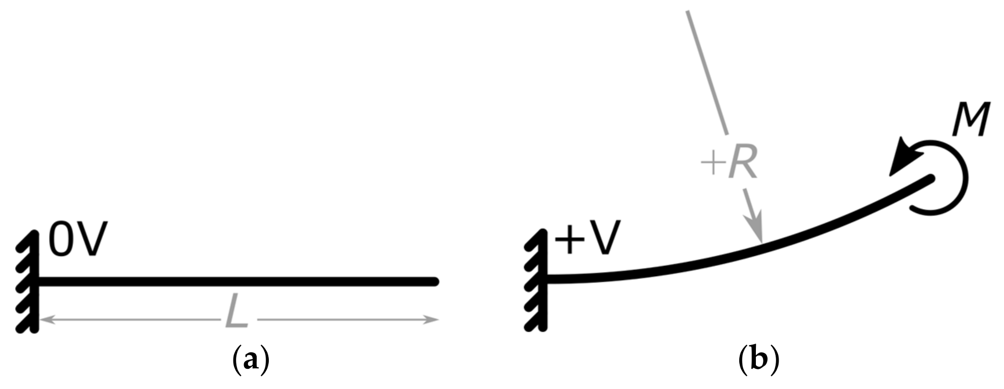
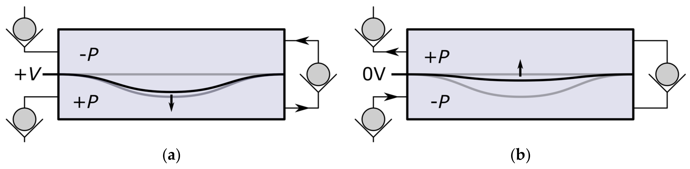
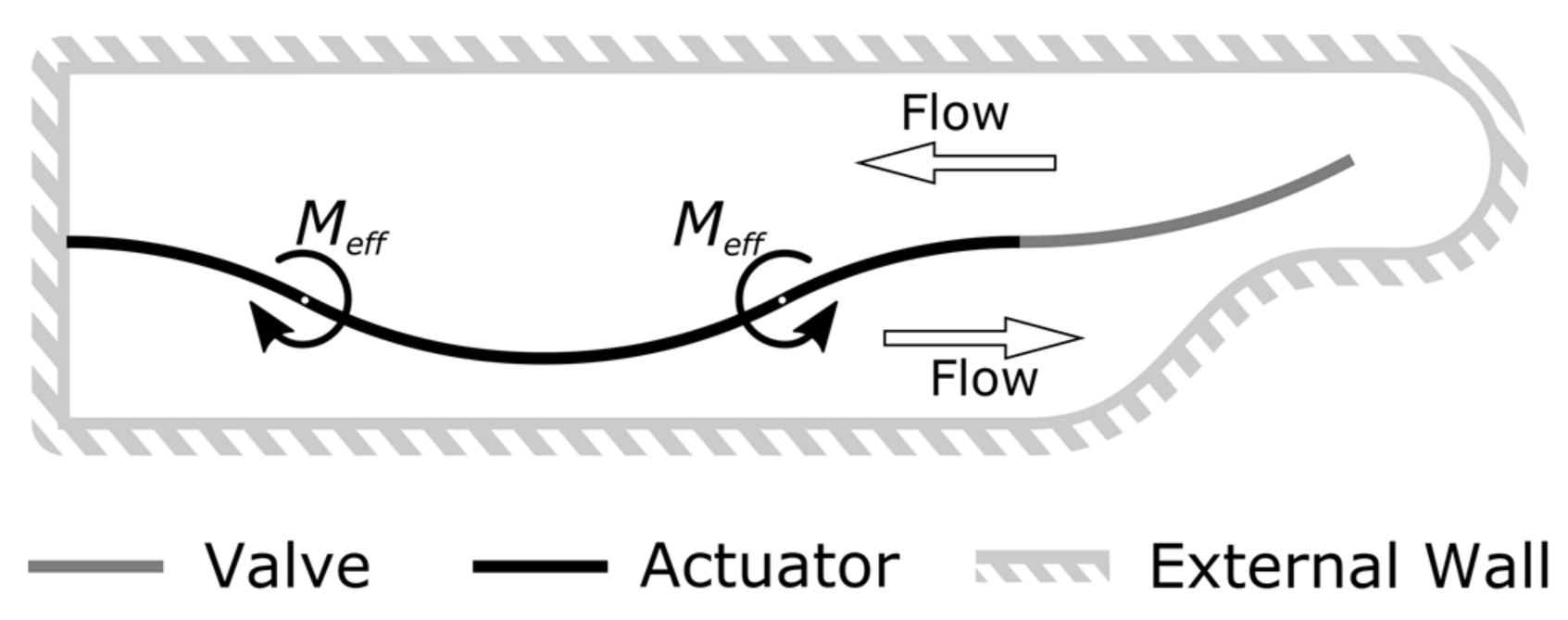
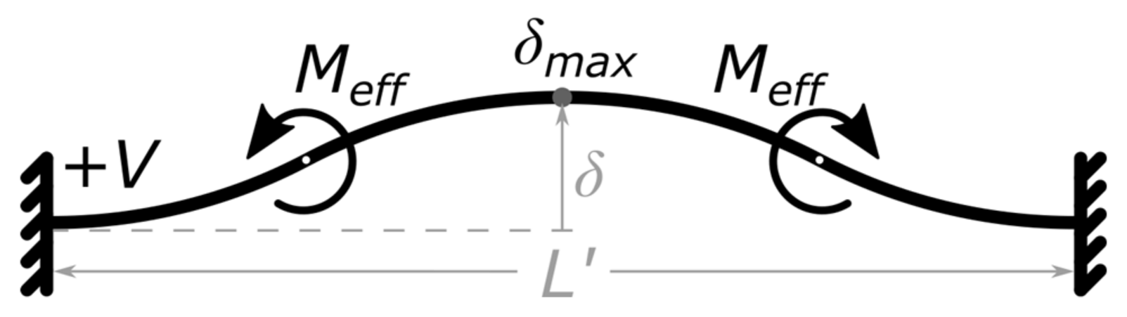
2.1. Actuation Theory of the In-Plane Micropump
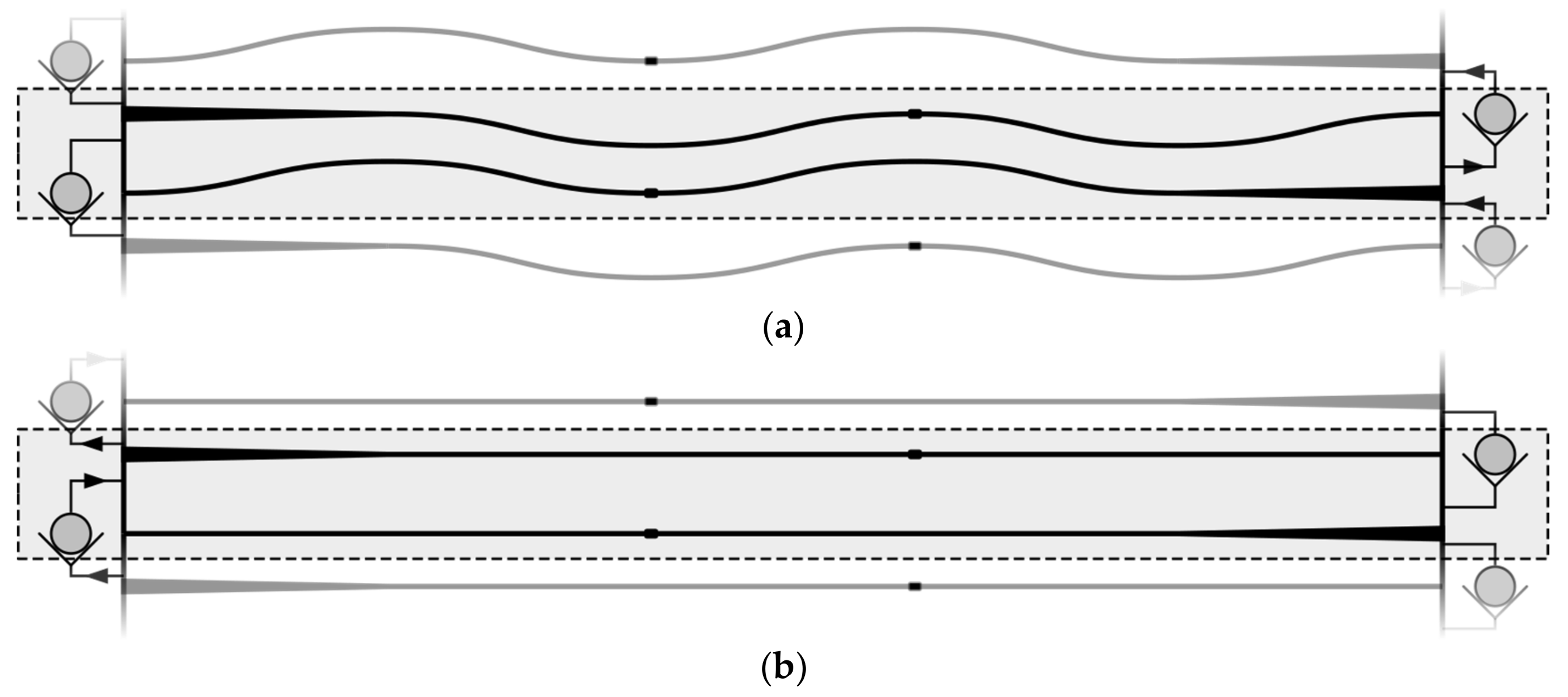
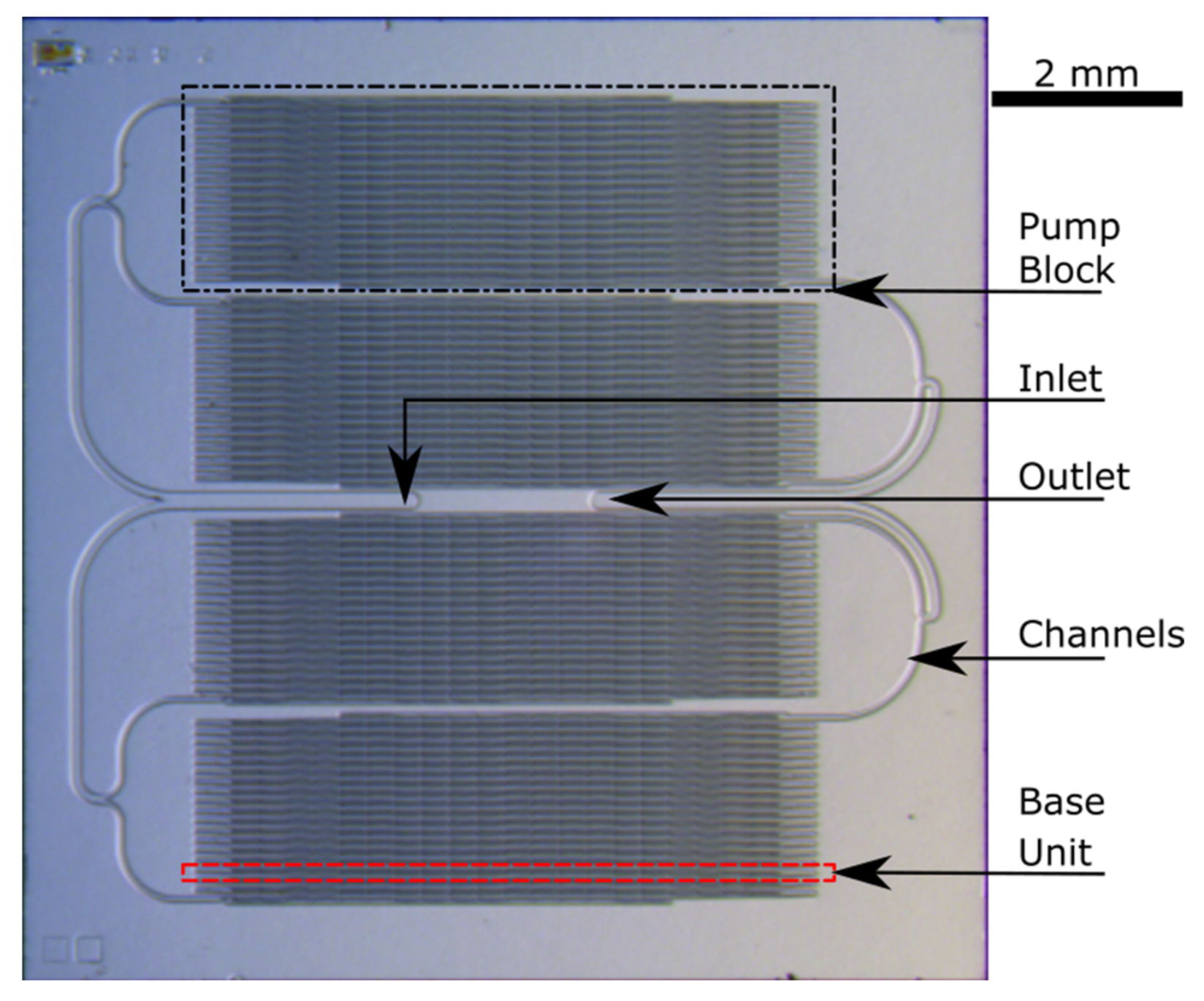
2.2. Base Unit Design of the Micropump
2.3. Modular Configuration of the Micropump
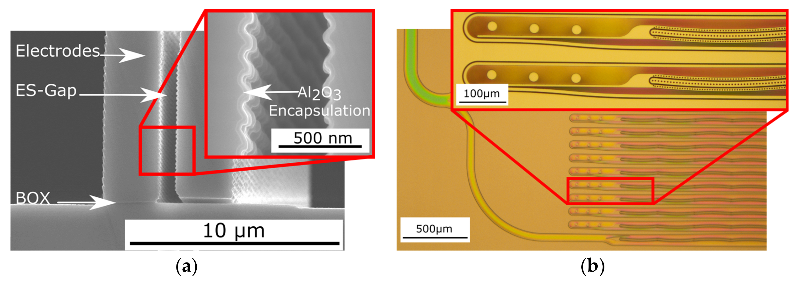
2.4. Micropump Test Structure Setup and Fabrication
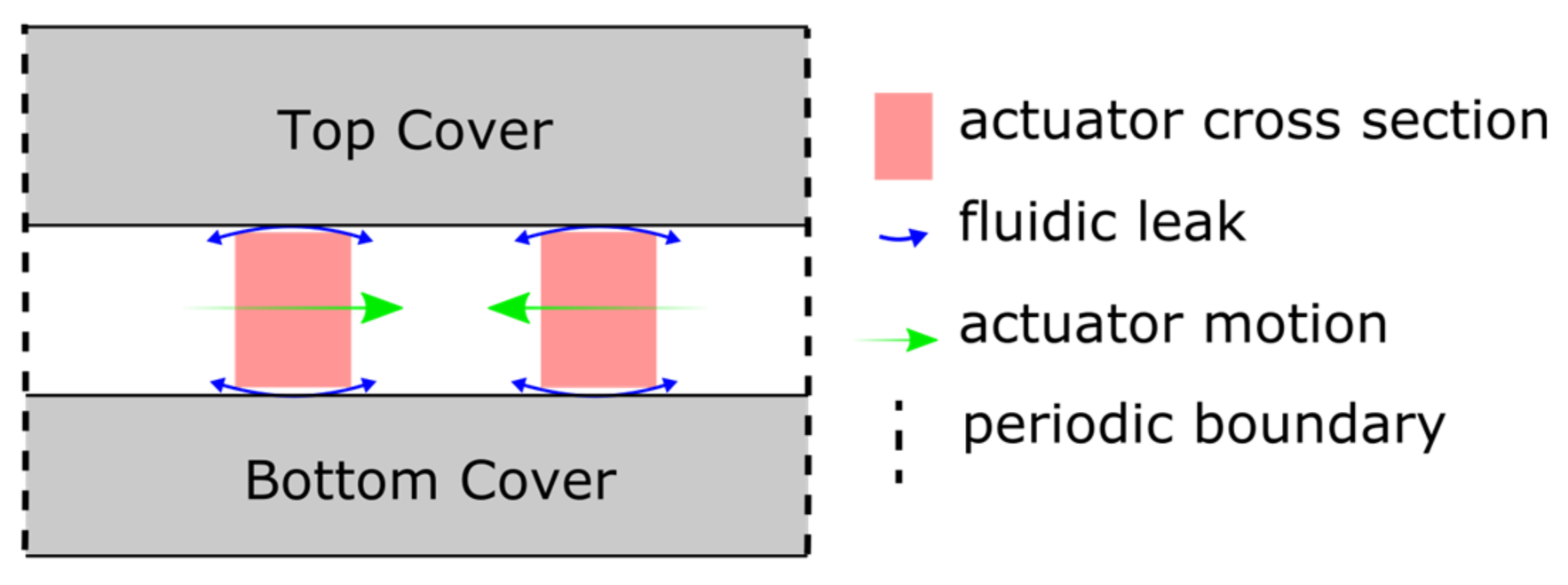
2.5. Simulation Setup of the Micropump
3. Results and Discussion
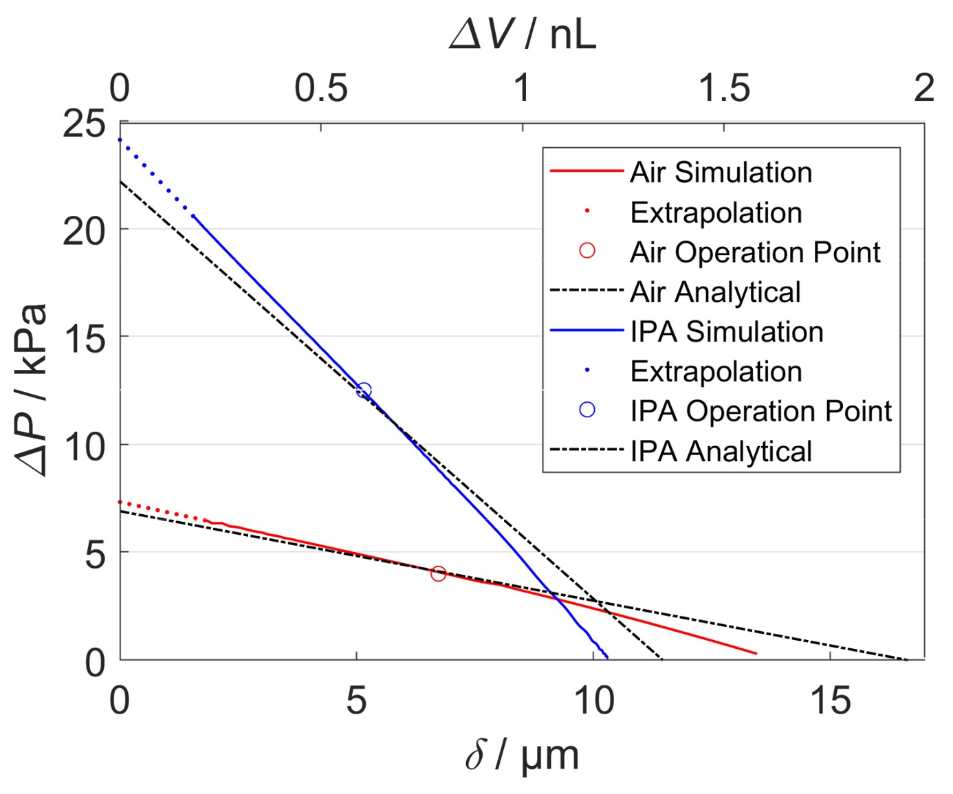
3.1. Simulations Results
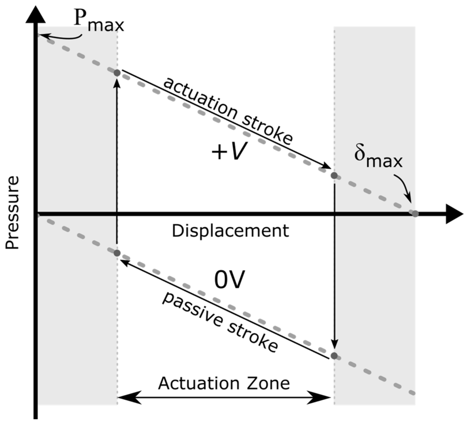
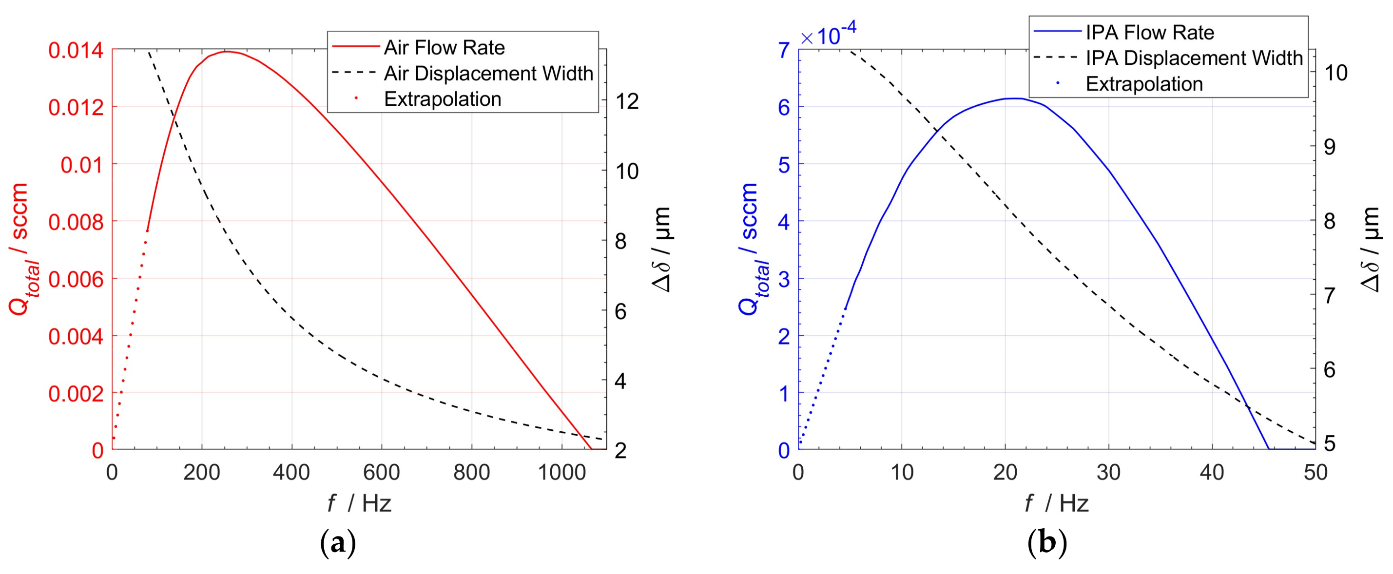
3.2. Actuation Zone and Dynamic Pump Behavior
3.3. Extrapolation of Simulation Results to the Designed Micropump Test Structure Chips
4. Conclusions
Acknowledgments
Author Contributions
Conflicts of Interest
Appendix A

| Toolbox | Property | Setup/Value |
|---|---|---|
| Transient Mechanical | Solver | Program Controlled |
| Large Deformation | On | |
| Numerical Damping | 0 | |
| Time Step | 10−4 s | |
| FLUENT | Solver | Transient, Pressure-Based, Absolut Velocity Formulation |
| Model | Viscous (Laminar) | |
| Material: Air | Ideal Gas (FLUENT Database) | |
| Material: IPA | Compressible Liquid (FLUENT Database) | |
| Dynamic Mesh | Smoothing (Spring-Based), Remeshing 2.5D, Implicit Update | |
| Solution Stabilization | Coefficient-Based = 10−3 | |
| Solution Methods | SIMPLE | |
| Spatial Discretization | Gradient: Least Squares Cell-based Pressure: PRESTO! | |
| Momentum: Second Order Upwind | ||
| Transient Formulation: Second Order-Implicit | ||
| Solution Controls | Default | |
| Residuals/Convergence-Criteria (Absolute) | Continuity, X-,Y-Velocity = 10−3 | |
| Initialization | Standard (Pressure, Velocity) = 0 | |
| Iterations/Coupling Step | 5 | |
| System Coupling | Min. Coupling Steps/Time Step | 5 |
| End Time | 10−1 s | |
| Time Step | 10−4 s | |
| Data Transfer/RMS-Convergence Target | 10−2 | |
| Under Relaxation Factor | 1 | |
| Ramping | None | |
| Execution. Control Sequence | Mechanical = 1, FLUENT = 2 |
Appendix B
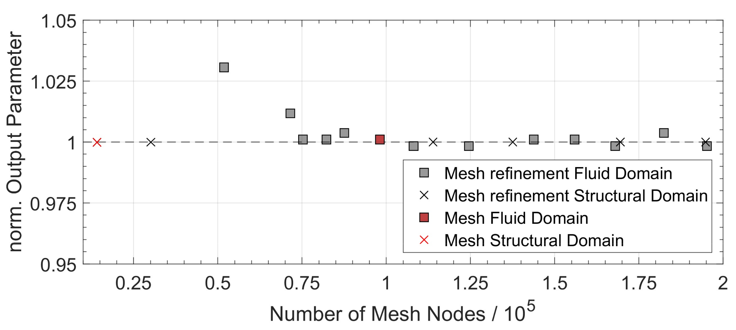
Error Analysis and Case Validation
References
- Singhal, V.; Garimella, S.V.; Raman, A. Microscale pumping technologies for microchannel cooling systems. Appl. Mech. Rev. 2004, 57, 191. [Google Scholar] [CrossRef]
- Kandlikar, S.G. Review and Projections of Integrated Cooling Systems for Three-Dimensional Integrated Circuits. J. Electron. Packag. 2014, 136, 24001. [Google Scholar] [CrossRef]
- Manz, A.; Graber, N.; Widmer, H.M. Miniaturized total chemical analysis systems: A novel concept for chemical sensing. Sens. Actuators B Chem. 1990, 1, 244–248. [Google Scholar] [CrossRef]
- Van der Schoot, B.H.; Jeanneret, S.; van den Berg, A.; de Rooij, N.F. A silicon integrated miniature chemical analysis system. Sens. Actuators B Chem. 1992, 6, 57–60. [Google Scholar] [CrossRef]
- Terry, S.C.; Jerman, J.H.; Angell, J.B. A gas chromatographic air analyzer fabricated on a silicon wafer. IEEE Trans. Electron Devices 1979, 26, 1880–1886. [Google Scholar] [CrossRef]
- Agah, M.; Lambertus, G.R.; Sacks, R.; Wise, K. High-Speed MEMS-Based Gas Chromatography. J. Microelectromech. Syst. 2006, 15, 1371–1378. [Google Scholar] [CrossRef]
- Lötters, J.C.; Lammerink, T.S.J.; Pap, M.G.; Sanders, R.G.P.; de Boer, M.J.; Mouris, A.J.; Wiegerink, R.J. Integrated micro Wobbe index meter towards on-chip energy content measurement. In Proceedings of the IEEE 26th International Conference on Micro Electro Mechanical Systems (MEMS), Taipei, Taiwan, 20–24 January 2013; pp. 965–968. [Google Scholar]
- Richter, M. Micropump for Empowering Sensors in Mobile Devices. 2017. Available online: www.emft.fraunhofer.de (accessed on 27 December 2017).
- Zengerle, R.; Ulrich, J.; Kluge, S.; Richter, M.; Richter, A. A bidirectional silicon micropump. Sens. Actuators A Phys. 1995, 50, 81–86. [Google Scholar] [CrossRef]
- Machauf, A.; Nemirovsky, Y.; Dinnar, U. A membrane micropump electrostatically actuated across the working fluid. J. Micromech. Microeng. 2005, 15, 2309. [Google Scholar]
- Kim, H.; Astle, A.A.; Najafi, K.; Bernal, L.P.; Washabaugh, P.D. An Integrated Electrostatic Peristaltic 18-Stage Gas Micropump with Active Microvalves. J. Microelectromech. Syst. 2015, 24, 192–206. [Google Scholar] [CrossRef]
- Laser, D.J.; Santiago, J.G. A review of micropumps. J. Micromech. Microeng. 2004, 14, R35–R64. [Google Scholar] [CrossRef]
- Richter, M.; Linnemann, R.; Woias, P. Robust design of gas and liquid micropumps. Sens. Actuators A Phys. 1998, 68, 480–486. [Google Scholar] [CrossRef]
- Zhang, W.-M.; Yan, H.; Peng, Z.-K.; Meng, G. Electrostatic pull-in instability in MEMS/NEMS: A review. Sens. Actuators A Phys. 2014, 214, 187–218. [Google Scholar] [CrossRef]
- Conrad, H.; Schenk, H.; Kaiser, B.; Langa, S.; Gaudet, M.; Schimmanz, K.; Stolz, M.; Lenz, M. A small-gap electrostatic micro-actuator for large deflections. Nat. Commun. 2015, 6, 10078. [Google Scholar] [CrossRef] [PubMed]
- Schenk, H.; Conrad, H.; Gaudet, M.; Uhlig, S.; Kaiser, B.; Langa, S.; Stolz, M.; Schimmanz, K. A contribution to the expansion of the applicability of electrostatic forces in micro transducers. SPIE OPTO 2017, 1011603. [Google Scholar] [CrossRef]
- Langa, S.; Conrad, H.; Kaiser, B.; Stolz, M.; Gaudet, M.; Uhlig, S.; Schimmanz, K.; Schenk, H. Technological aspects of a new micro-electro-mechanical actuation principle: Nano-e-drive. Microsyst. Technol. 2017, 15, S153S164. [Google Scholar] [CrossRef]
- Gaudet, M.; Uhlig, S.; Stolz, M.; Arscott, S.; Conrad, H.; Langa, S.; Kaiser, B.; Schenk, H. Electrostatic bending actuators with a liquid filled nanometer scale gap. In Proceedings of the 2017 IEEE 30th International Conference on Micro Electro Mechanical Systems (MEMS), Las Vegas, NV, USA, 22–26 January 2017. [Google Scholar]
- Gross, D. Technische Mechanik, 11th ed.; Springer: Berlin, Germany, 2012. [Google Scholar]
- Gerke, W. Elektrische Maschinen und Aktoren. Eine Anwendungsorientierte Einfhrung; Oldenbourg Wissenschaftsv: München, Germany, 2013. [Google Scholar]
- Schomburg, W.K. Introduction to Microsystem Design; Springer: Berlin/Heidelberg, Germany, 2011. [Google Scholar]
- Chimakurthi, S.K.; Reuss, S.; Tooley, M.; Scampoli, S. ANSYS Workbench System Coupling: A state-of-the-art computational framework for analyzing multiphysics problems. Eng. Comput. 2017. [Google Scholar] [CrossRef]
- Bruus, H. Theoretical Microfluidics; Oxford University Press: Oxford, UK, 2008. [Google Scholar]
- Tas, N.R.; Haneveld, J.; Jansen, H.V.; Elwenspoek, M.; van den Berg, A. Capillary filling speed of water in nanochannels. Appl. Phys. Lett. 2004, 85, 3274–3276. [Google Scholar] [CrossRef]
- ANSYS Customer Portal, Fluid Structure Interaction FSI with ANSYS Fluent 17.0, Lecture 3-Co-Simulation Setup. Available online: https://support.ansys.com/ (accessed on 13 March 2017).


| Design | A | B |
|---|---|---|
| Medium | Air | IPA |
| 1.225 kg/m³ | 790 kg/m³ | |
| 1.79 × 10⁻⁵ Pas | 0.0012 Pas | |
| 8.44 × 10⁻⁹ Nm² | 1.05 × 10⁻⁸ Nm² | |
| 4.49 × 10⁻¹⁰ Nm² | 5.58 × 10⁻¹⁰ Nm² | |
| 2.20 × 10⁻⁷ Nm | 3.65 × 10⁻⁷ Nm | |
| 2.35 × 10⁻⁸ Nm | 3.89 × 10⁻⁸ Nm | |
| 3.2 mm | 2.3 mm | |
| 0.3 mm | 0.3 mm | |
| 10−3 s | 10−3 s | |
| 10−4 s | 10−4 s | |
| 10−1 s | 10−1 s |
| Design | A | B |
|---|---|---|
| Medium | Air | IPA |
| Size | 10 × 7 × 0.9 mm³ | 10 × 10 × 0.9 mm³ |
| Actuation voltage | 300 V | 100 V |
| # of parallel blocks | 2 | 4 |
| # of base units per block | 19 | 19 |
| # of NED actuators per base unit | 4 | 4 |
| Operational differential pressure | 130 kPa | 210 kPa |
| Expected flow rate | 0.11 sccm | 0.01 sccm |
| Operational actuation frequency | 265 Hz | 21 Hz |
© 2018 by the authors. Licensee MDPI, Basel, Switzerland. This article is an open access article distributed under the terms and conditions of the Creative Commons Attribution (CC BY) license (http://creativecommons.org/licenses/by/4.0/).
Share and Cite
Uhlig, S.; Gaudet, M.; Langa, S.; Schimmanz, K.; Conrad, H.; Kaiser, B.; Schenk, H. Electrostatically Driven In-Plane Silicon Micropump for Modular Configuration. Micromachines 2018, 9, 190. https://doi.org/10.3390/mi9040190
Uhlig S, Gaudet M, Langa S, Schimmanz K, Conrad H, Kaiser B, Schenk H. Electrostatically Driven In-Plane Silicon Micropump for Modular Configuration. Micromachines. 2018; 9(4):190. https://doi.org/10.3390/mi9040190
Chicago/Turabian StyleUhlig, Sebastian, Matthieu Gaudet, Sergiu Langa, Klaus Schimmanz, Holger Conrad, Bert Kaiser, and Harald Schenk. 2018. "Electrostatically Driven In-Plane Silicon Micropump for Modular Configuration" Micromachines 9, no. 4: 190. https://doi.org/10.3390/mi9040190
APA StyleUhlig, S., Gaudet, M., Langa, S., Schimmanz, K., Conrad, H., Kaiser, B., & Schenk, H. (2018). Electrostatically Driven In-Plane Silicon Micropump for Modular Configuration. Micromachines, 9(4), 190. https://doi.org/10.3390/mi9040190