Characterization of Laser Beam Shaping Optics Based on Their Ablation Geometry of Thin Films


Abstract
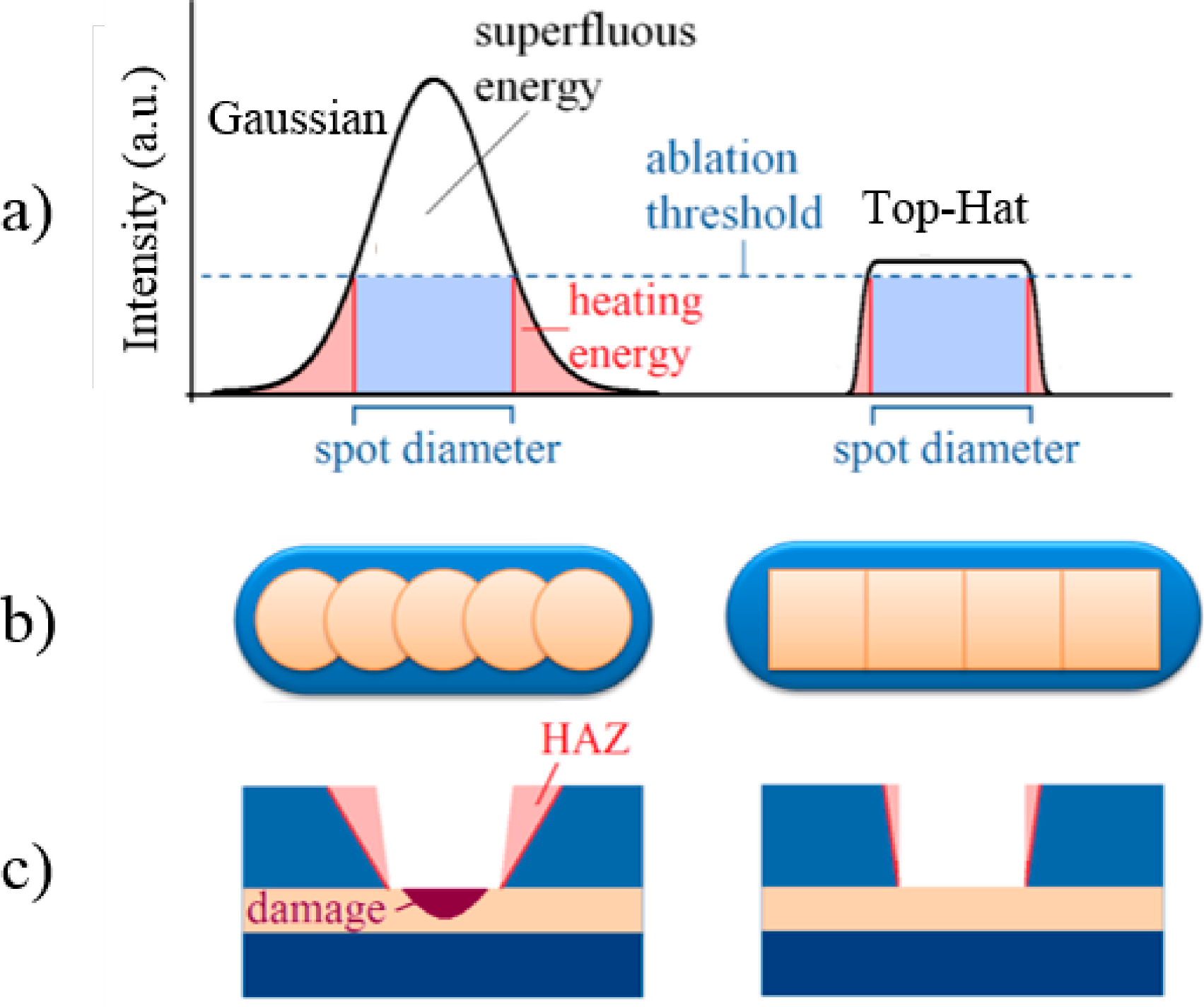
:1. Introduction

2. Experimental Section
2.1. Laser System
2.2. Material Setup
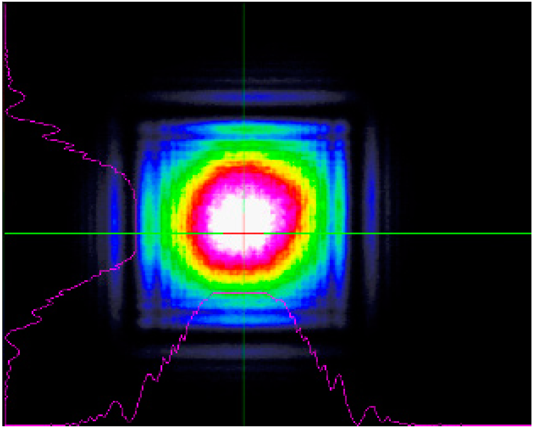
2.3. Beam Shaping Optics


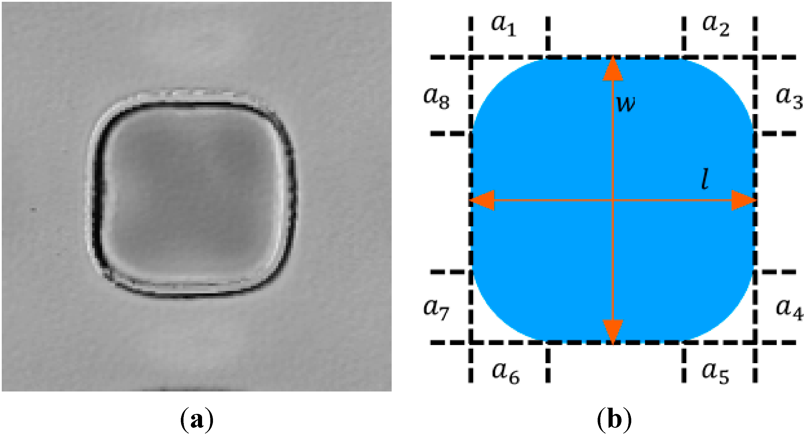
2.4. Method of Evaluation

2.5. Pre-Alignment

3. Results and Discussion
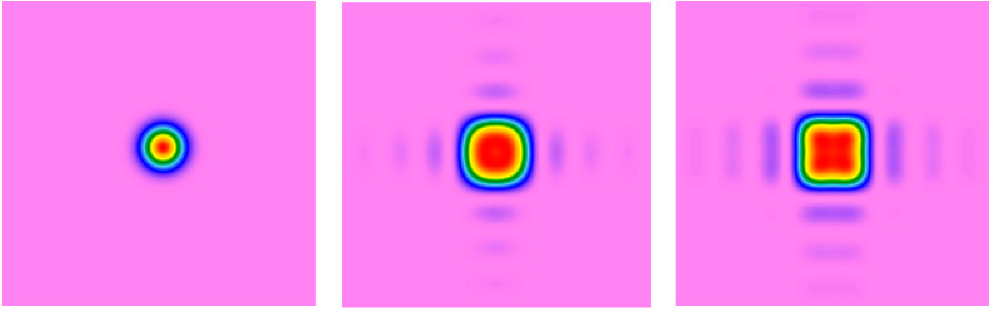
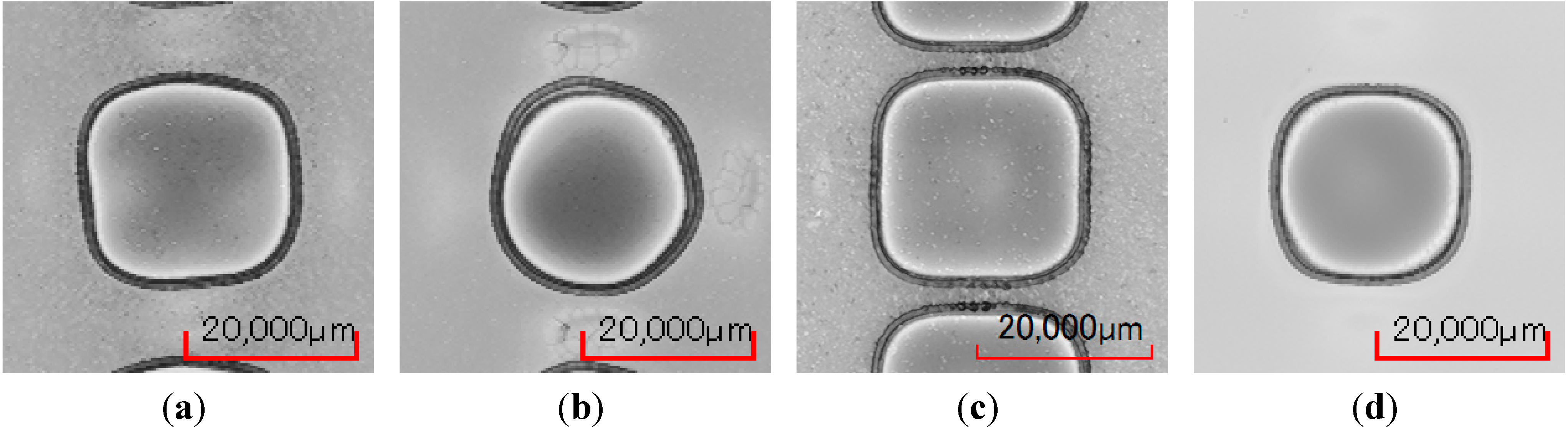
3.1. Variation of the Focal Positon


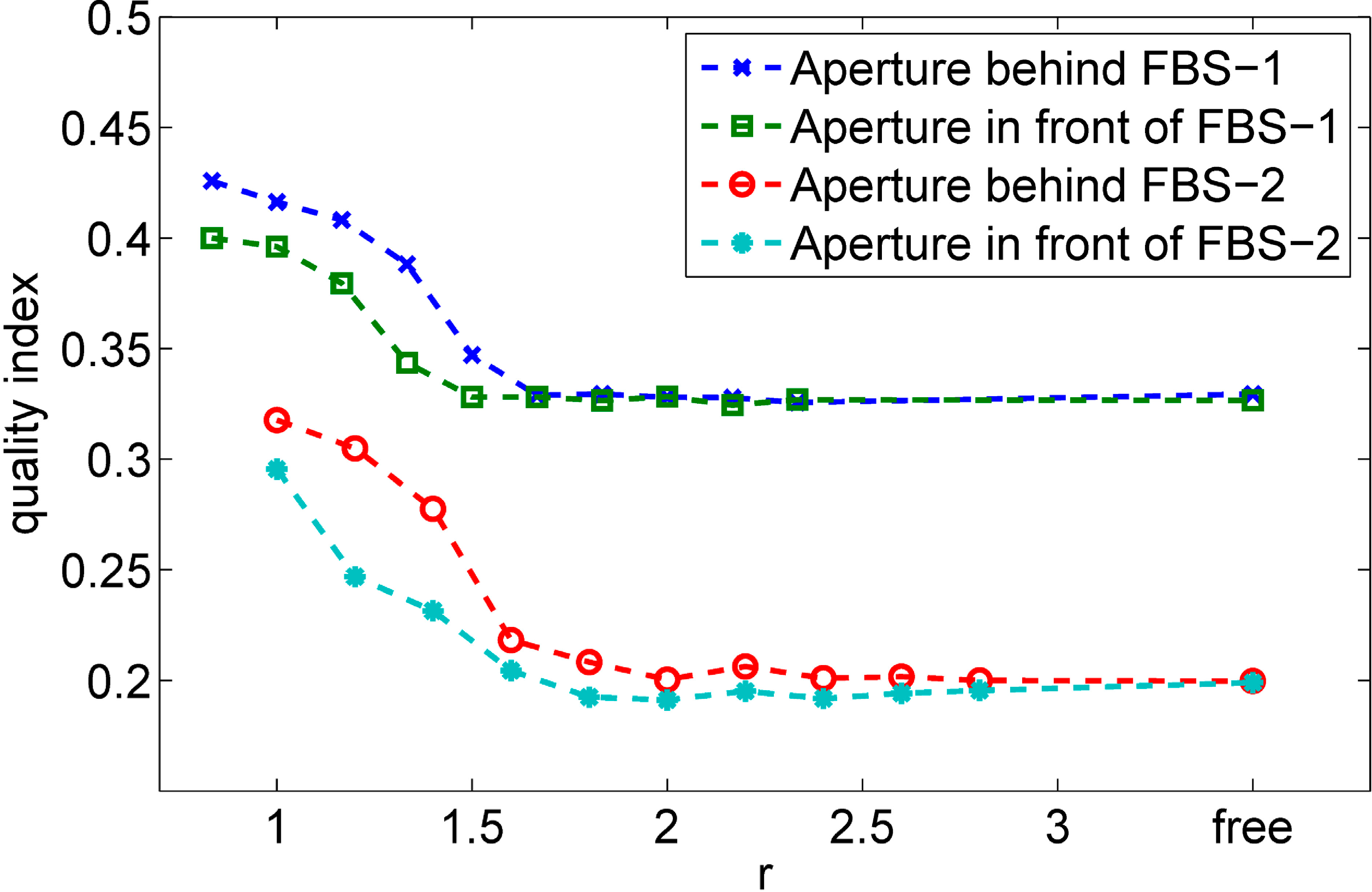
3.2. Limitations by a Free Aperture in the Beam Path


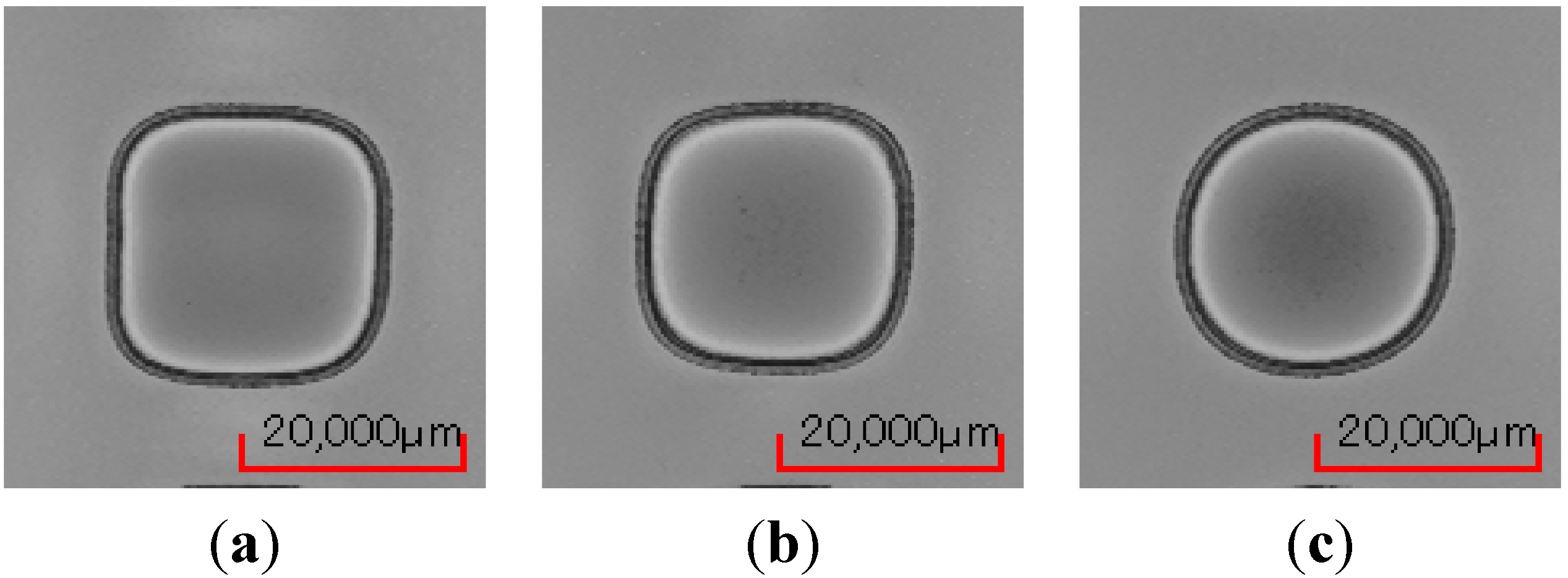
3.3. Lateral Displacement of the Beam Shaping Optical Element

| Lateral Displacement | 0 μm | 250 μm | 500 μm | 750 μm | 1 mm |
|---|---|---|---|---|---|
| FBS-1 |  |  |  |  |  |
| FBS-2 |  | 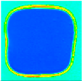 | 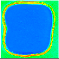 | 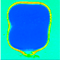 | 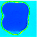 |
| Lateral Displacement | 1.25 mm | 1.50 mm | 1.75 mm | 2 mm | 2.25 mm |
| FBS-1 |  |  |  |  | 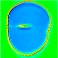 |
| FBS-2 | 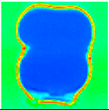 |  | 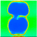 |  | 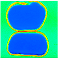 |
4. Conclusions
Acknowledgments
Author Contributions
Conflicts of Interest
References
- Baird, B.; Gerke, T.; Wieland, K.; Paudel, N. P2 and P3 Spatially Shaped Laser Scribing of CdTe and a-Si Thin Film Solar Cells Using a 532 nm Picosecond MOFPA. In Proceedings of 26th European Photovoltaic Solar Energy Conference and Exhibition, Hamburg, Germany, 5–8 September 2011; pp. 2471–2474.
- Raciukaitis, G.; Stankevicius, E.; Gecys, P.; Gedvilas, M.; Bischoff, C.; Jäger, E.; Umhofer, U.; Völklein, F. Laser processing by using diffractive optical laser beam shaping technique. J. Laser Micro/Nanoeng. 2011, 6, 37–43. [Google Scholar]
- Steiger, E.; Scharnagl, M.; Kemnitzer, M.; Laskin, A. Optimization of the Structuring Processes of CI(G)S Thin-Film Solar Cells with an Ultrafast Picosecond Laser and a Special Beam Shaping Optics. In Proceedings of 28th International Congress on Applications of Lasers & Electro-Optics (ICALEO), Orlando, FL, USA, 2–5 November 2009.
- Rung, S.; Rexhepi, M.; Bischoff, C.; Hellmann, R. Laserscribing of thin films using Top-Hat laser beam profiles. J. Laser Micro/Nanoeng. 2013, 8, 309–314. [Google Scholar]
- Hauschild, D.; Homburg, O.; Mitra, T.; Ivanenko, M.; Jarczynski, M.; Meinschien, J.; Bayer, A.; Lissotschenko, V. Optimizing Laser Beam Profiles Using Micro-Lens Arrays for Efficient Material Processing: Applications to Solar Cells. In Proceedings of SPIE 7202 Laser-Based Micro- and Nanopackaging and Assembly III, San Jose, CA, USA, 28–29 January 2009. [CrossRef]
- Bovatsek, J.; Patel, R.S. High-Power ns-Pulsed Q-switched Laser Technology with Flattop Beam-Shaping Technique for Efficient Industrial Laser Processing. In Proceedings of 28th International Congress on Applications of Lasers & Electro-Optics (ICALEO), Orlando, FL, USA, 29 Ocotober–1 November 2007.
- Rung, S.; Bischoff, C.; Jäger, E.; Umhofer, U.; Hellmann, R. Laser Thin Film Ablation with Multiple Beams and Tailored Beam Profiles. In Proceedings of SPIE 8967 Laser Applications in Microelectronic and Optoelectronic Manufacturing (LAMOM) XIX, San Francisco, CA, USA, 3–6 Februray 2014. [CrossRef]
- Eidelloth, S.; Neubert, T.; Brendemühl, T.; Hermann, S.; Giesel, P.; Brendel, R. High Speed Laser Structuring of Crystalline Silicon Solar Cells. In Proceedings of 34th IEEE Photovoltaic Specialists Conference (PVSC), Philadelphia, PA, USA, 7–12 June 2009; pp. 002389–002394.
- Tsai, C.Y.; Tsai, C.Y. Development of amorphous/microcrystalline silicon tandem thin-film solar modules with low output voltage, high energy yield, low light-induced degradation, and high damp-heat reliability. J. Nanomater. 2014, 2014, 861741. [Google Scholar] [CrossRef]
- Liu, J.M. Simple technique for measurements of pulsed Gaussian-beam spot sizes. Opt. Lett. 1982, 7, 196–198. [Google Scholar]
- TOPAG. Available online: http://www.topag.de (accessed on 1 October 2014).
© 2014 by the authors; licensee MDPI, Basel, Switzerland. This article is an open access article distributed under the terms and conditions of the Creative Commons Attribution license (http://creativecommons.org/licenses/by/4.0/).
Share and Cite
Rung, S.; Barth, J.; Hellmann, R. Characterization of Laser Beam Shaping Optics Based on Their Ablation Geometry of Thin Films. Micromachines 2014, 5, 943-953. https://doi.org/10.3390/mi5040943
Rung S, Barth J, Hellmann R. Characterization of Laser Beam Shaping Optics Based on Their Ablation Geometry of Thin Films. Micromachines. 2014; 5(4):943-953. https://doi.org/10.3390/mi5040943
Chicago/Turabian StyleRung, Stefan, Johannes Barth, and Ralf Hellmann. 2014. "Characterization of Laser Beam Shaping Optics Based on Their Ablation Geometry of Thin Films" Micromachines 5, no. 4: 943-953. https://doi.org/10.3390/mi5040943
APA StyleRung, S., Barth, J., & Hellmann, R. (2014). Characterization of Laser Beam Shaping Optics Based on Their Ablation Geometry of Thin Films. Micromachines, 5(4), 943-953. https://doi.org/10.3390/mi5040943