Abstract
To enhance the RF power properties of CMOS-compatible gold-free GaN devices, this work introduces a kind of GaN-on-Si HEMT with a low parasitic regrown ohmic contact technology. Attributed to the highly doped n+ InGaN regrown layer and smooth morphology of gold-free ohmic stacks, the lowest ohmic contact resistance (Rc) was presented as 0.072 Ω·mm. More importantly, low RF loss and low total dislocation density (TDD) of the Si-based GaN epitaxy were achieved by a designed two-step-graded (TSG) transition structure for the use of scaling-down devices in high-frequency applications. Finally, the fabricated GaN HEMTs on the Si substrate presented a maximum drain current (Idrain) of 1206 mA/mm, a peak transconductance (Gm) of 391 mS/mm, and a breakdown voltage (VBR) of 169 V. The outstanding material and DC performances strongly encourage a maximum output power density (Pout) of 10.2 W/mm at 8 GHz and drain voltage (Vdrain) of 50 V in active pulse mode, which, to our best knowledge, updates the highest power level for gold-free GaN devices on Si substrates. The power results reflect the reliable potential of low parasitic regrown ohmic contact technology for future large-scale CMOS-integrated circuits in RF applications.
1. Introduction
Gallium nitride (GaN) HEMTs on Si substrates have appealed to be an effective technology for mm-wave, high power, and large-scale heterogeneous integration circuit applications due to their large wafer scalability, cost-effectiveness, promising RF power properties, and natural CMOS-compatible substrate platform [1,2]. However, most reported Si-based GaN devices are based on the gold-containing ohmic contact which is incompatible with CMOS circuits and, more than that, formed by a high-temperature alloying process with a high thermal budget, rough morphology, and high-frequency parasitic effect [3,4]. Thus, a gold-free ohmic contact technology, along with low ohmic contact resistance (Rc) and low thermal budget, is crucial for the realization of GaN-on-Si RF devices with high output power and efficiency.
Available low ohmic contact methods mainly include ion implantation, barrier-recessed ohmic contact, and regrown highly doped n+ GaN. However, for GaN-on-Si devices, ion implantation for highly doped AlGaN in the ohmic region is hard to realize. This is because the activation process requires a high temperature (>1200 °C), which exceeds the typical growth temperature of Si-based GaN, thereby degrading the quality of the epitaxy material [4]. Barrier-recessed ohmic technologies were applied with different gold-free metal stacks for GaN-on-Si devices with low Rc [5], but etch-induced damage and high thermal budget remain to be solved. Among these techniques, regrown n+ GaN ohmic contact is acknowledged as an effective method for low Rc and smooth morphology, avoiding an additional high-temperature alloying process [6,7]. However, reports are quite limited on regrown ohmic contact with gold-free metal stacks for the GaN-on-Si platform.
In this work, a gold-free regrown ohmic contact technology was implemented for GaN HEMTs on a Si substrate. Owing to the highly doped n+ InGaN layer and Ti/Al/Pt/Ti ohmic metal stack, a lowest Rc of 0.072 Ω·mm was obtained without an additional high-temperature annealing process, which effectively suppresses the high-frequency parasitic effect. Except for the low Rc, crystalline quality and RF loss from Si-based GaN epitaxy materials remain critical to mitigate the high-frequency parasitic effect, especially for device scaling design in GaN/Si-CMOS integration applications. A high-quality ultrathin buffer technology using a two-step-graded (TSG) transition structure was introduced to reduce the dislocation density of the GaN-on-Si epitaxy platform, which has been proposed in our previous work [8]. Based on the TSG transition technology, a remarkably low total dislocation density (TDD) of 1.68 × 109 cm−2 was achieved, which compares favorably with other state-of-the-art GaN-on-Si RF devices. To further investigate the parasitic effect of Si-based GaN epitaxy material, RF loss was evaluated by coplanar waveguide (CPW) transmission line structures on the GaN epitaxy on the Si substrate with a low value of 0.24 dB/mm at 8 GHz. The advanced crystalline quality and low RF loss manifest the advancement of TSG transition technology. Consequently, the fabricated gold-free AlGaN/GaN HEMTs exhibited a saturated drain current (Idrain) of 1206 mA/mm and breakdown voltage (VBR) of 169 V, resulting in a maximum power density (Pout) of 10.2 W/mm with peak PAE of 50.5% at 8 GHz, which are the highest reported values among gold-free GaN-on-Si devices.
2. Material Growth and Device Fabrication
As described in Figure 1a, the AlGaN/GaN epitaxy structure was grown on a high-resistivity (HR) Si substrate (ρ > 10 kΩ·cm) through metal oxide chemical vapor deposition (MOCVD). The epitaxial structure comprises an AlN nucleation layer, the TSG transition layers, a GaN buffer layer, an unintentionally doped (UID) GaN channel layer, and an AlGaN barrier layer from bottom to top. To suppress dislocation density induced from large lattice mismatch between GaN and the Si substrate, the TSG transition structure was applied to acquire a high-quality epitaxy [8]. The detailed TSG buffer includes the 30 nm Al0.4Ga0.6N stress layer and an AlN/Al0.2Ga0.8N composed layer of 90 nm total. The TDD of GaN epitaxy structures was calculated with a low value of 1.68 × 109 cm−2 in ω scanning mode [9], proving the high growth quality of TSG transition technology. Hall measurements under room temperature presented the sheet electron concentration and electron mobility of 1.14 × 1013 cm−2 and 1950 cm2/V·s, respectively.
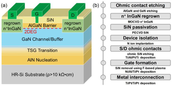
Figure 1.
(a) Schematic and (b) process flow of the gold-free AlGaN/GaN HEMTs on Si substrate using regrown ohmic contact technology with dimensions of Lg = 0.25 μm, Wg = 100 μm, and Lsd = 4 μm.
Figure 1b exhibits the fabrication process flow of the gold-free GaN devices with the regrown ohmic contact in detail. The regrown process flow began with the removal of the AlGaN barrier layer and GaN channel layer in the ohmic region by photolithography and Cl-based etching. To ensure better contact between the regrown n+ InGaN and the 2DEG of the channel, the low-damage etching condition was developed. The n+ InGaN with Si doping concentration of 2 × 1020 cm−3 was grown at 800 °C by MOCVD. After that, the two-step wet rinse processes were implemented for removal of regrown n+ InGaN outside the ohmic contact regions. Prior to regrowth, a SiO2 mask layer was deposited to protect the access region. In the first step, hydrofluoric acid (HF) was used to selectively remove the undesired regrown material covering the access region, leveraging its vigorous reaction with SiO2. Subsequently, a mixture of acetone and isopropyl alcohol was applied to thoroughly cleanse the area and eliminate any residual reactants or contaminants.
To protect the surface of the AlGaN barrier layer, a SiN passivation layer was deposited by plasma-enhanced chemical vapor deposition (PECVD). Prior to the SiN passivation, in situ NH3 plasma pre-treatment was introduced in the chamber to improve the passivation effect, and device planar isolation of the active region was carried out via nitrogen ion implantation. Then, the Ti/Al/Pt/Ti gold-free ohmic metal stacks of source and drain pads were deposited on the regrown n+ InGaN. For gate fabrication, the gate foot definition was realized by electron beam lithography (EBL), and then the SiN of this region was removed by F-based plasma. And the T-gate structure was fabricated by the deposition of Ni/Al/Ti/Pt gold-free metal stacks to ensure the complete CMOS-compatible flow scheme. Finally, the interconnection of the metal was accomplished as Ti/Pt/Ti/Pt by electron beam evaporation to achieve a low parasitic resistance. The devices feature the gate length (Lg), gate width (Wg), and source–drain spacing (Lsd) of 0.25 μm, 100 μm, and 4 μm, respectively.
3. Results and Discussion
Figure 2a demonstrates the I-V characteristics of Ti/Al/Pt/Ti ohmic contact resistivity as a function of increasing spacings from 2 μm to 32 μm, measured by the transmission line model (TLM). Profiting from the highly doped regrown n+ InGaN and low-resistive ohmic metal stack, the extracted lowest Rc was 0.072 Ω·mm, with high uniformity across the whole wafer as presented in Figure 2b. The specific contact resistivity of the regrown ohmic contact is also evaluated from the TLM structures as 1.87 × 10⁻⁷ Ω·cm−2. The high-angle annular dark-field scanning transmission electron microscope (HAADF-STEM, Talos F200X G4 TEM, Thermo Fisher Company) and the energy dispersive X-ray spectroscopy (EDS) element mapping of the regrown n+ InGaN and ohmic metal stack are exhibited in Figure 3b,c.
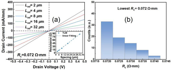
Figure 2.
(a) TLM I-V measurements of the Ti/Al/Pt/Ti ohmic contact resistivity, and (b) a distribution of the Rc for the gold-free GaN HEMTs on Si substrate.

Figure 3.
(a) EDS element mapping micrograph of the gate foot region, (b) the HAADF-STEM image of the whole region consisting of the gate and ohmic region, and (c) EDS micrograph of the ohmic region for the fabricated GaN-on-Si devices.
The gold-free T-gate microstructure was also depicted by HAADF-STEM as shown in Figure 3a,b, demonstrating uniform coverage of the Ni/Al/Ti/Pt gate metal. The DC I-V characteristics of the device were assessed by the Keysight B1500A semiconductor parameter analyzer (Keysight Technologies (China) Co., Ltd.). Figure 4a shows transfer I-V properties of the gold-free GaN-on-Si devices under Vdrain = 6 V and gate-to-source voltage sweep from −6 V to 2 V. The threshold voltage (Vth) was extracted as −2.4 V. It can be seen that the Idrain and the Gm of the device were measured as 1206 mA/mm and 391 mS/mm, respectively, which demonstrates the excellent electrostatic control of the gold-free gate electrode to the 2DEG channel. Off-state breakdown characteristics of the fabricated GaN HEMT with Lsd = 4 μm were measured under Vgate = −8 V. Leveraging the TSG transition structure’s high-quality GaN epitaxy, we achieved VBR = 169 V defined at 1 mA/mm, confirming excellent high-voltage performance for RF power applications (Figure 5a). To assess the dynamic current collapse of the gold-free GaN devices, double-pulsed output I-V characteristics were measured by the Keithley 4200-SCS system, with a pulse width of 500 ns and a duty cycle of 0.05%. Due to the low-dislocation-density GaN epitaxy and high-quality SiN passivation, the small current collapse ratio (CCR) of Vgate = 2 V of merely 9.4% was achieved up to the quiescent bias (VGQ = −8 V, VDQ = 40 V), predicting high dynamic operation for RF domains.
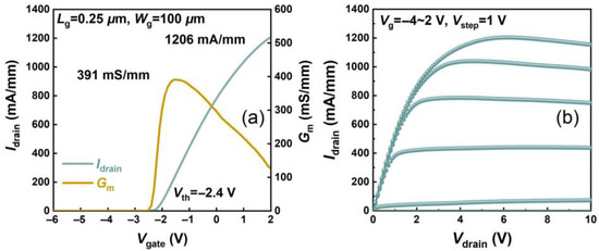
Figure 4.
(a) Linear transfer I-V and (b) output I-V properties of the gold-free GaN HEMTs on Si substrate.
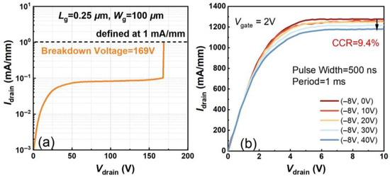
Figure 5.
(a) Off-state breakdown properties and (b) double-pulsed output I-V characteristics of gold-free GaN HEMTs on Si substrate with Lsd = 4 μm.
The CPW transmission line model was adopted to measure RF loss at different frequencies for the grown GaN-on-Si epitaxy materials. Based on S-parameter measurements using Agilent E8363B PNA network analyzer (Agilent Technologies, Inc.) calibrated with the through–reflect–line (TRL) calibration standard, the RF loss was measured from 0.1 GHz to 20 GHz. A low value of RF Loss at 8 GHz was 0.24 dB/mm, as marked in Figure 6a. As shown in Figure 6b, the RF loss at 8 GHz and the low total dislocation density of the GaN buffer in this work both stay at a high level among reported epitaxial structures for GaN-on-Si RF applications [10,11,12,13,14,15]. The results demonstrate that the TSG structure on the HR-Si substrate achieves both low RF loss and high crystalline quality, facilitating high RF power performance.
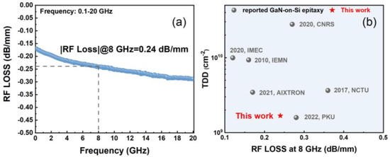
Figure 6.
(a) RF loss versus frequency from 0.1 to 20 GHz; (b) benchmark of TDD and RF loss at 8 GHz among reported GaN-on-Si epitaxial materials [10,11,12,13,14,15].
The small-signal performance of the fabricated gold-free GaN HEMTs on silicon substrates has been thoroughly characterized. RF measurements of the GaN-on-Si HEMT were conducted from 0.1 to 40 GHz using an Agilent 8363B network analyzer with short–open–through calibration. The measured data were de-embedded using cold and hot FET techniques [16]. As shown in Figure 7, the small-signal RF performance of the 0.25 μm devices is presented, with S-parameters measured from 0.1 to 40 GHz at VDS of 6 V. The resulting fT and fmax values are 45 GHz and 110 GHz, respectively. The extracted intrinsic parameters were summarized in the right table of Figure 7.
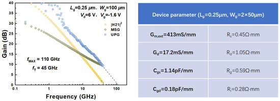
Figure 7.
Measured fT/fmax of the gold-free GaN HEMTs on Si substrates at VDS = 6 V after de-embedding. The right table demonstrates the extracted intrinsic parameters.
Figure 8a exhibits the large-signal power performance of the gold-free AlGaN/GaN devices at 8 GHz measured by a Maury active load-pull system in pulse mode. The pulse width and duty cycle are 20 μs and 10%, respectively. Ascribing to the low contact resistance, high breakdown voltage, and low RF loss, the device exhibited a high Pout of 10.2 W/mm and a peak PAE of 50.5% at the operation voltage of 50 V, as demonstrated in Figure 8a. As indicated in Figure 8b, the gold-free GaN devices in this work present the highest output power density among the reported RF GaN-on-Si devices [5,17,18,19,20,21,22,23,24,25,26]. Such a high-power performance verifies the advancement of the low parasitic regrown ohmic contact technology in gold-free GaN devices for GaN/Si-CMOS heterogeneous integration applications. With the high demand for exploring higher frequency, building upon these advanced technologies, the combination of high-quality GaN-on-Si epitaxial growth and ultra-low contact resistance provides a solid foundation for future high-frequency applications.
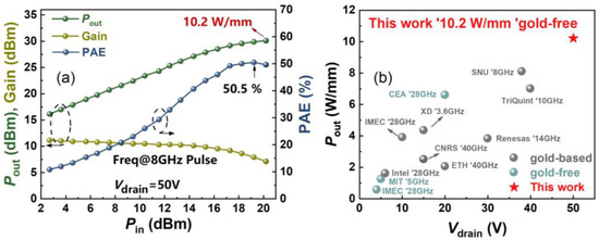
Figure 8.
(a) Large-signal power measurements at 8 GHz of the gold-free GaN-on-Si devices by active load-pull system in pulse mode. (b) Benchmark of Pout versus Vdrain among state-of-the-art GaN-on-Si reports [5,17,18,19,20,21,22,23,24,25,26].
4. Conclusions
In this paper, a GaN-on-Si HEMT employing low parasitic regrown ohmic contact technology and a TSG transition structure was presented. The highly doped regrown n+ InGaN layer and Ti/Al/Pt/Ti ohmic metal structure contribute to the low Rc of 0.072 Ω·mm. In addition, the high-quality GaN layer and low RF loss ensure high Idrain and VBR for high-voltage RF operation. Eventually, the proposed gold-free GaN devices on Si substrates achieve a highest power performance of 10.2 W/mm with peak PAE of 50.5% at 8 GHz and 50 V operation. These results break the performance limitations of gold-free GaN-on-Si RF devices, demonstrating the potential of low-resistive regrown ohmic contact technology for future heterogeneous integration applications.
Author Contributions
Conceptualization, J.D.; data curation, J.D.; formal analysis, K.C. and T.P.; funding acquisition, B.H. and L.Y.; investigation, Y.C., H.L. (Hailin Liu) and Q.C.; project administration, B.H., L.Y., X.M. and Y.H.; validation, M.Z. and M.W.; writing—original draft, J.D.; writing—review and editing, H.L. (Hao Lu) and B.H. All authors have read and agreed to the published version of the manuscript.
Funding
This work was supported by the National Natural Science Foundation of China (NSFC) under Grant Nos. 62474135, 62234009, 62090014, 62404165; in part by the Fundamental Research Funds for the Central Universities of China under Grant QTZX25069, YJSJ24020, ZYTS25217, ZYTS25218; in part by the Postdoctoral Fellowship Program of CPSF under Grant GZB20230557; in part by the China Postdoctoral Science Foundation under Grant 2023M732730; in part by the Natural Science Basic Research Program of Shaanxi under Program No. 2024JC-YBQN-0611.
Data Availability Statement
Data are contained within the article.
Conflicts of Interest
The authors declare no conflicts of interest.
References
- Peralagu, U.; Alian, A.; Putcha, V.; Khaled, A.; Rodriguez, R.; Sibaja-Hernandez, A.; Chang, S.; Simoen, E.; Zhao, S.E.; De Jaeger, B.; et al. CMOS-compatible GaN-based devices on 200 mm-Si for RF applications: Integration and performance. In Proceedings of the 2020 IEEE International Electron Devices Meeting (IEDM), San Francisco, CA, USA, 12–18 December 2020; p. 17. [Google Scholar] [CrossRef]
- Then, H.W.; Huang, C.Y.; Krist, B.; Jun, K.; Lin, K.; Nidhi, N.; Michaelos, T.; Mueller, B.; Paul, R.; Peck, J.; et al. 3D heterogeneous integration of high performance high-K metal gate GaN NMOS and Si PMOS transistors on 300mm high-resistivity Si substrate for energy-efficient and compact power delivery, RF (5G and beyond) and SoC applications. In Proceedings of the 2019 IEEE International Electron Devices Meeting (IEDM), San Francisco, CA, USA, 7–11 December 2019; p. 17. [Google Scholar] [CrossRef]
- Niranjan, S.; Rao, A.; Muralidharan, R.; Sen, P.; Nath, D.N. Performance Comparison of Au-Based and Au-Free AlGaN/GaN HEMT on Silicon. IEEE Trans. Electron Devices 2022, 69, 1014–1019. [Google Scholar] [CrossRef]
- Çakmak, H.; Öztürk, M.; Özbay, E.; Imer, B. Nonalloyed Ohmic Contacts in AlGaN/GaN HEMTs With MOCVD Regrowth of InGaN for Ka-Band Applications. IEEE Trans. Electron Devices 2021, 68, 1–5. [Google Scholar] [CrossRef]
- Morvan, E.; Gobil, Y.; Morisot, F.; Biscarat, J.; Charles, M.; Lugo, J.; Divay, A.; Medbouhi, M.; Charlet, I.; Delprato, J.; et al. 6.6 W/mm 200 mm CMOS compatible AlN/GaN/Si MIS-HEMT with in-situ SiN gate dielectric and low temperature ohmic contacts. In Proceedings of the 2023 International Electron Devices Meeting (IEDM), San Francisco, CA, USA, 9–13 December 2023; pp. 1–4. [Google Scholar] [CrossRef]
- Song, B.; Zhu, M.; Hu, Z.; Qi, M.; Nomoto, K.; Yan, X.; Cao, Y.; Jena, D.; Xing, H.G. Ultralow-Leakage AlGaN/GaN High Electron Mobility Transistors on Si With Non-Alloyed Regrown Ohmic Contacts. IEEE Electron Device Lett. 2016, 37, 16–19. [Google Scholar] [CrossRef]
- Qie, H.; Liu, J.; Li, Q.; Sun, Q.; Gao, H.; Sun, X.; Zhou, Y.; Yang, H. Selective area epitaxy of degenerate n-GaN for HEMT ohmic contact by MOCVD. Appl. Phys. Lett. 2022, 121, 212106. [Google Scholar] [CrossRef]
- Du, J.; Hou, B.; Yang, L.; Zhang, Y.; Zhu, Q.; Zhang, M.; Wu, M.; Huang, S.; Song, F.; Lu, H.; et al. High RF Performance E-Mode GaN-on-Si HEMTs With Pout of 5.32 W/mm Using High-Quality Ultrathin Buffer. IEEE Electron Device Lett. 2025, 46, 349–352. [Google Scholar] [CrossRef]
- Heinke, H.; Kirchner, V.; Einfeldt, S.; Hommel, D. X-ray diffraction analysis of the defect structure in epitaxial GaN. Appl. Phys. Lett. 2000, 77, 2145–2147. [Google Scholar] [CrossRef]
- Frayssinet, E.; Nguyen, L.; Lesecq, M.; Defance, N.; Barros, M.G.; Comyn, R.; Ngo, T.H.; Zielinski, M.; Portail, M.; Jaeger, J.-C.D.; et al. Metalorganic Chemical Vapor Phase Epitaxy Growth of Buffer Layers on 3C-SiC/Si (111) Templates for AlGaN/GaN High Electron Mobility Transistors with Low RF Losses. Phys. Status Solidi A 2020, 217, 1900760. [Google Scholar] [CrossRef]
- Chang, S.; Zhao, M.; Spampinato, V.; Franquet, A.; Chang, L. The influence of AlN nucleation layer on RF transmission loss of GaN buffer on high resistivity Si (111) substrate. Semicond. Sci. Technol. 2020, 35, 035029. [Google Scholar] [CrossRef]
- Lecourt, F.; Douvry, Y.; Defrance, N.; Hoel, V.; Cordier, Y.; DeJaeger, J.C. Analysis of AlGaN/GaN Epi-material on Resistive Si(111) Substrate for MMIC Applications in Millimeter Wave Range. In Proceedings of the 2010 5th European Microwave Integrated Circuits Conf. (EuMIC, 2010), Paris, France, 27–28 September 2010; p. 33. [Google Scholar]
- Mauder, C.; Hahn, H.; Marx, M.; Gao, Z.; Oligschlaeger, R.; Zweipfennig, T.; Nochlak, A.; Negra, R.; Kalisch, H.; Vescan, A.; et al. Investigation and reduction of RF loss induced by Al diffusion at the AlN/Si(111) interface in GaN-based HEMT buffer stacks. Semicond. Sci. Technol. 2021, 36, 075008. [Google Scholar] [CrossRef]
- Luong, T.T.; Lumbantoruan, F.; Chen, Y.-Y.; Ho, Y.-T.; Weng, Y.-C.; Lin, Y.-C.; Chang, S.; Chang, E.-Y. RF loss mechanisms in GaN-based high-electron-mobility-transistor on silicon: Role of an inversion channel at the AlN/Si interface. Phys. Status Solidi A 2017, 214, 1600944.1–1600944.7. [Google Scholar] [CrossRef]
- Ma, C.; Yang, X.; Shen, J.; Liu, D.; Cai, Z.; Chen, Z.; Tang, J.; Sang, L.; Xu, F.; Wang, X.; et al. Low RF loss and low dislocation density of GaN grown on high-resistivity Si substrates. Appl. Phys. Express 2022, 15, 31003.1–31003.4. [Google Scholar] [CrossRef]
- Jarndal, A.; Kompa, G. A new small-signal modeling approach applied to GaN devices. IEEE Trans. Microwave Theory Tech. 2005, 53, 3440. [Google Scholar] [CrossRef]
- Lee, M.-S.; Kim, D.; Eom, S.; Cha, H.-Y.; Seo, K.-S. A Compact 30-W AlGaN/GaN HEMTs on Silicon Substrate With Output Power Density of 8.1 W/mm at 8 GHz. IEEE Electron Device Lett. 2014, 35, 995–997. [Google Scholar] [CrossRef]
- Dumka, D.C.; Lee, C.; Tserng, H.Q.; Saunier, P.; Kumar, M. AlGaN/GaN HEMTs on Si substrate with 7 W/mm output power density at 10 GHz. Electron. Lett. 2004, 40, 1023–1024. [Google Scholar] [CrossRef]
- Then, H.W.; Radosavljevic, M.; Jun, K.; Koirala, P.; Krist, B.; Talukdar, T.; Thomas, N.; Fischer, P. Gallium Nitride and Silicon Transistors on 300 mm Silicon Wafers Enabled by 3-D Monolithic Heterogeneous Integration. IEEE Trans. Electron Devices 2020, 67, 5306–5314. [Google Scholar] [CrossRef]
- Murase, Y.; Asano, K.; Takenaka, I.; Ando, Y.; Takahashi, H.; Sasaoka, C. T-Shaped Gate GaN HFETs on Si With Improved Breakdown Voltage and fMAX. IEEE Electron Device Lett. 2014, 35, 524–526. [Google Scholar] [CrossRef]
- Zhou, Y.; Zhu, J.; Zhang, B.; Wang, Q.; Qin, L.; Wei, L.; Li, M.; Chen, B.; Zhang, M.; Hao, Y.; et al. High RF Performance AlGaN/GaN HEMTs on 6-in Si Substrate for Low Voltage Applications. IEEE Electron Device Lett. 2025, 46, 549–552. [Google Scholar] [CrossRef]
- ElKashlan, R.; Khaled, A.; Yadav, S.; Yu, H.; Peralagu, U.; Alian, A.; Collaert, N.; Wambacq, P.; Parvais, B. mm-Wave GaN-on-Si HEMTs with a P SAT of 3.9 W/mm at 28 GHz. In Proceedings of the 2023 IEEE/MTT-S International Microwave Symposium-IMS 2023, San Diego, CA, USA, 11–16 June 2023; pp. 24–27. [Google Scholar]
- Medjdoub, F.; Zegaoui, M.; Grimbert, B.; Ducatteau, D.; Rolland, N.; Rolland, P.A. First Demonstration of High-Power GaN-on-Silicon Transistors at 40 GHz. IEEE Electron Device Lett. 2012, 33, 1168–1170. [Google Scholar] [CrossRef]
- Marti, D.; Tirelli, S.; Alt, A.R.; Roberts, J.; Bolognesi, C.R. 150-GHz Cutoff Frequencies and 2-W/mm Output Power at 40 GHz in a Millimeter-Wave AlGaN/GaN HEMT Technology on Silicon. IEEE Electron Device Lett. 2012, 33, 1372–1374. [Google Scholar] [CrossRef]
- Xie, H.; Liu, Z.; Hu, W.; Gao, Y.; Lee, K.E.; Guo, Y.-X.; Ng, G.I. CMOS-Compatible InAlN/GaN HEMTs on Silicon for RF Power Amplifiers in 5G Mobile SoCs. In Proceedings of the 2021 IEEE MTT-S International Microwave Workshop Series on Advanced Materials and Processes for RF and THz Applications (IMWS-AMP), Chongqing, China, 15–17 November 2021; pp. 397–399. [Google Scholar] [CrossRef]
- Parvais, B.; Alian, A.; Peralagu, U.; Rodriguez, R.; Yadav, S.; Khaled, A.; ElKashlan, R.Y.; Putcha, V.; Sibaja-Hernandez, A.; Zhao, M.; et al. GaN-on-Si mm-wave RF Devices Integrated in a 200mm CMOS Compatible 3-Level Cu BEOL. In Proceedings of the 2020 IEEE International Electron Devices Meeting (IEDM), San Francisco, CA, USA, 12–18 December 2020; pp. 8.1.1–8.1.4. [Google Scholar] [CrossRef]
Disclaimer/Publisher’s Note: The statements, opinions and data contained in all publications are solely those of the individual author(s) and contributor(s) and not of MDPI and/or the editor(s). MDPI and/or the editor(s) disclaim responsibility for any injury to people or property resulting from any ideas, methods, instructions or products referred to in the content. |
© 2025 by the authors. Licensee MDPI, Basel, Switzerland. This article is an open access article distributed under the terms and conditions of the Creative Commons Attribution (CC BY) license (https://creativecommons.org/licenses/by/4.0/).