
Design and Evaluation of a Capacitive Micromachined Ultrasonic Transducer(CMUT) Linear Array System for Thickness Measurement of Marine Structures Under Varying Environmental Conditions

 ,
,  , and
, and
Abstract
1. Introduction
2. CMUT Linear Array Design and Fabrication
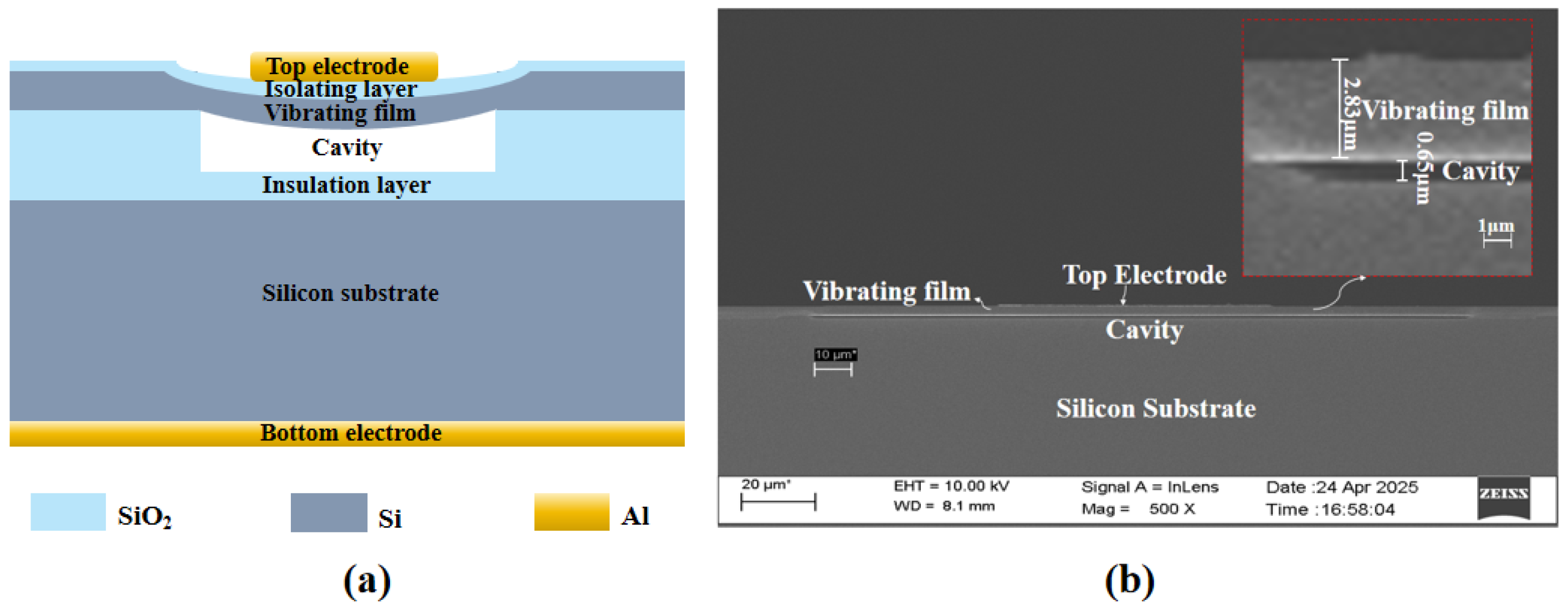
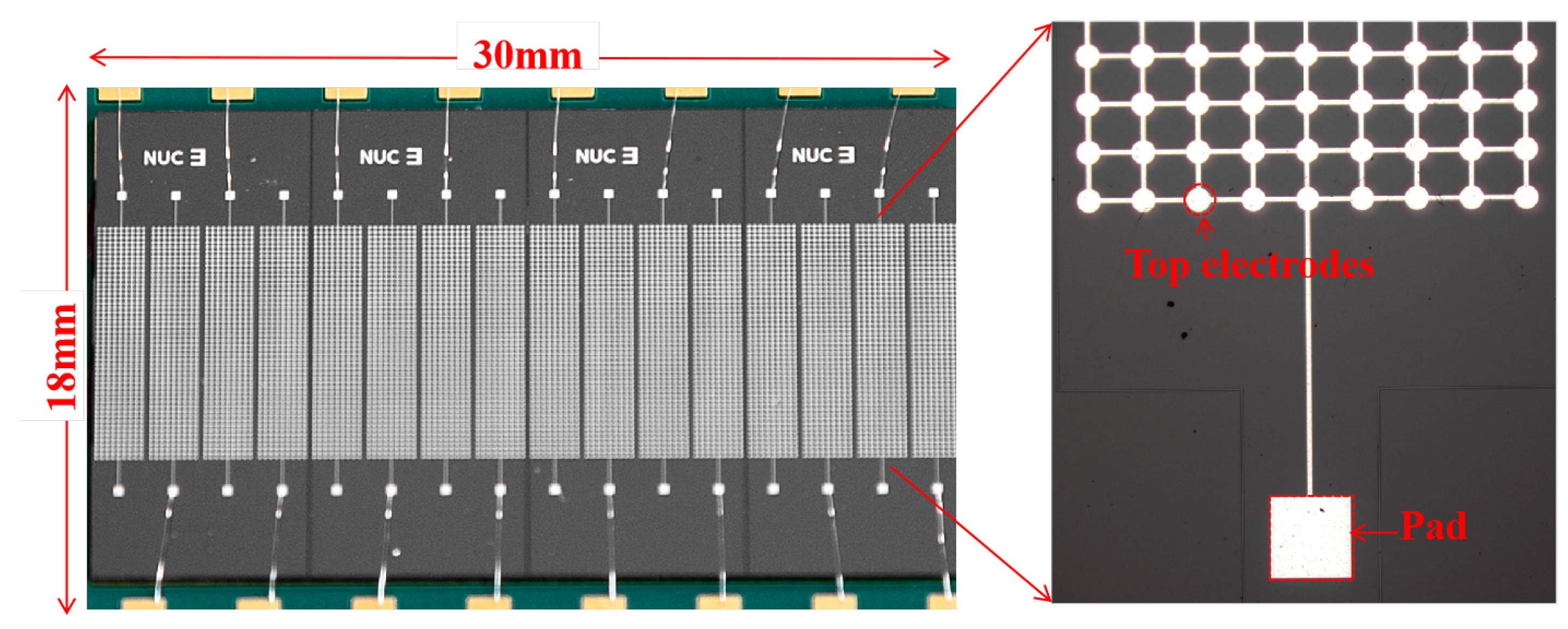
2.1. Design
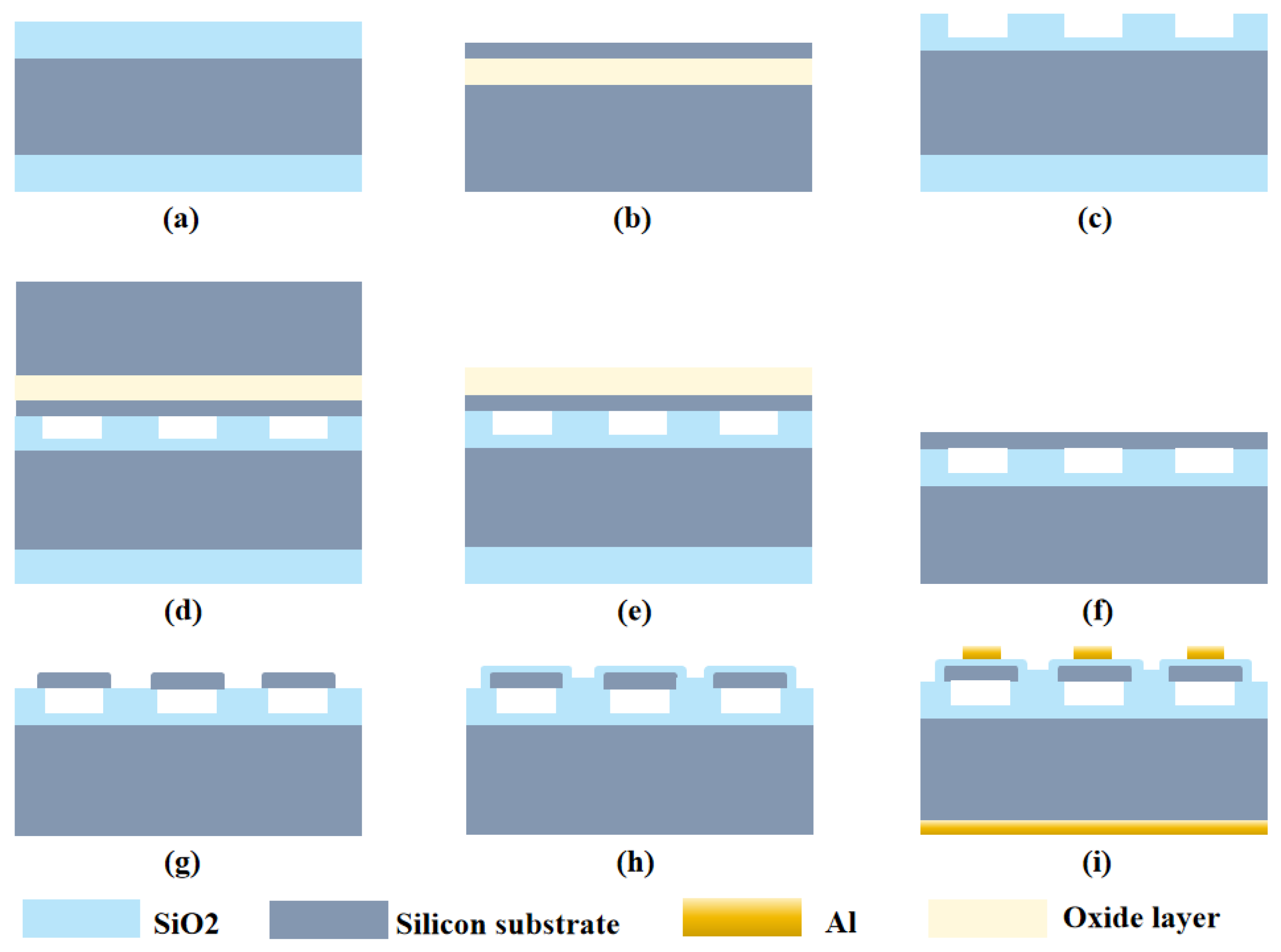
2.2. Fabrication
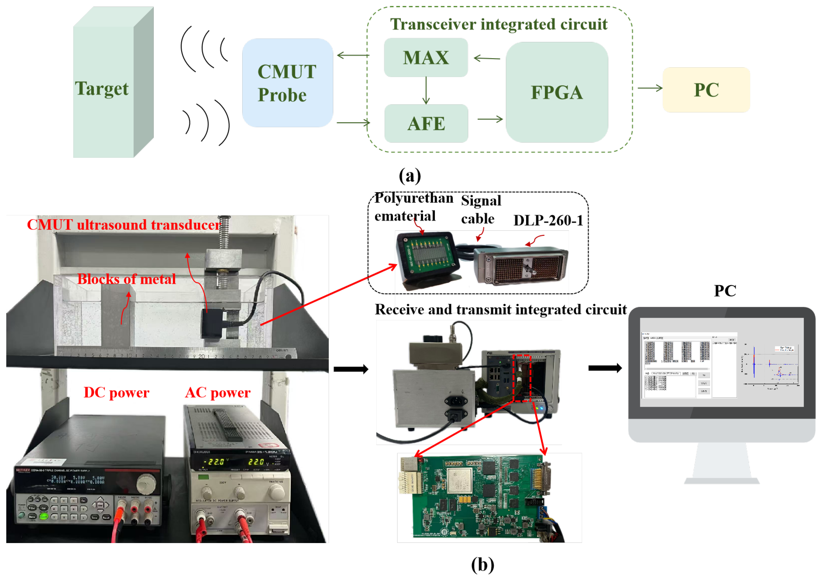
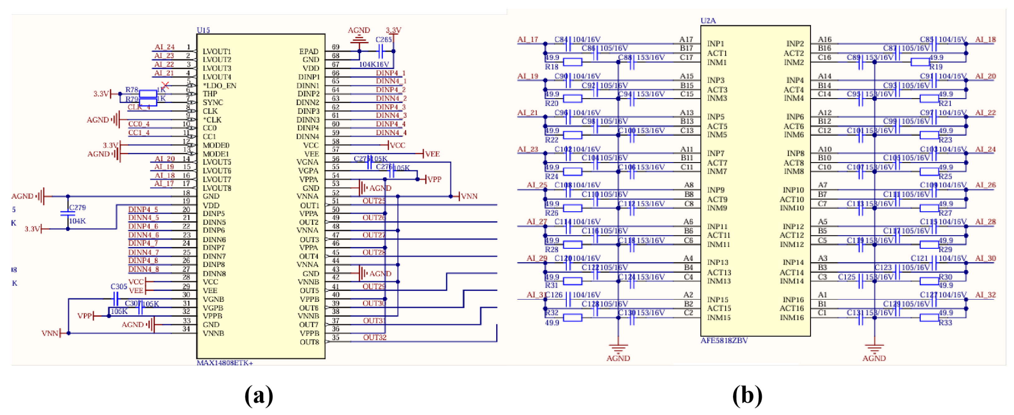
3. Development and Operational Principle of Thickness Detection System
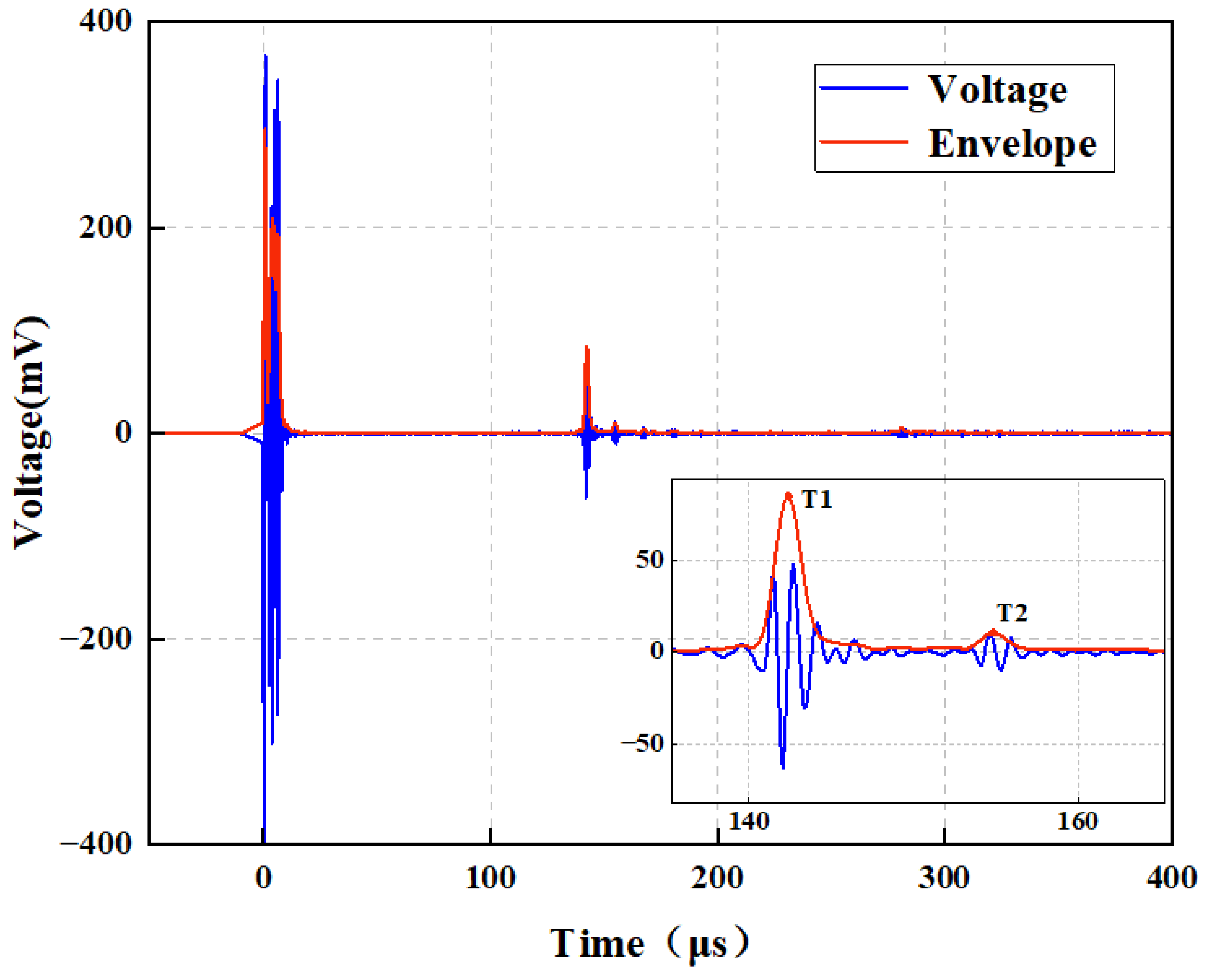
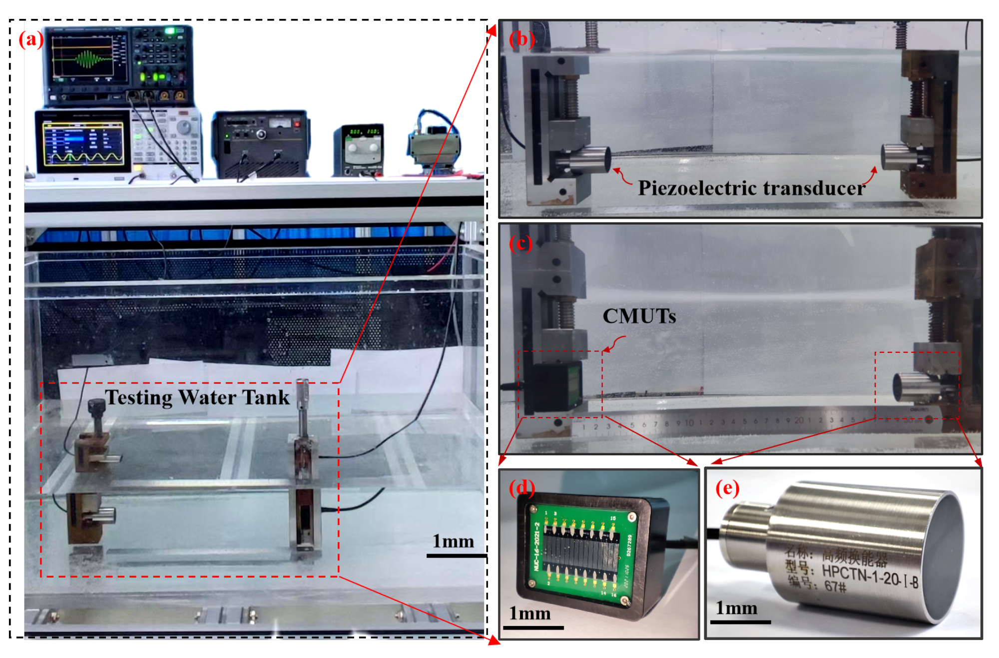
4. Experimental Results and Discussion
5. Conclusions
Author Contributions
Funding
Data Availability Statement
Conflicts of Interest
References
- Liu, Y.; Jing, B.; Zhang, G.; Pei, J.; Jia, L.; Geng, Y.; Bai, Z.; Zhang, J.; Guo, Z.; Wang, J.; et al. Design and Algorithm Integration of High-Precision Adaptive Underwater Detection System Based on MEMS Vector Hydrophone. Micromachines 2024, 15, 514. [Google Scholar] [CrossRef]
- Vicen-Bueno, R.; Carrasco-Álvarez, R.; Jarabo-Amores, M.P.; Nieto-Borge, J.C.; Alexandre-Cortizo, E. Detection of Ships in Marine Environments by Square Integration Mode and Multilayer Perceptrons. IEEE Trans. Instrum. Meas. 2021, 60, 712–724. [Google Scholar] [CrossRef]
- Chen, B.-Q.; Zhang, X.; Guedes-Soares, C. The effect of general and localized corrosions on the collapse pressure of subsea pipelines. Ocean Eng. 2022, 247, 110719. [Google Scholar] [CrossRef]
- Lu, Y.; Fu, W.; Xue, D. Deformation Characteristics of Soft Marine Soil Tested under Cyclic Loading with Low Frequency. Adv. Civ. Eng. 2020, 2020, 8875315. [Google Scholar] [CrossRef]
- Liu, H.; Chen, W.; Tan, Y.; Meng, G.; Liu, H.; Cheng, Y.; Liu, H.W. Characterizations of the biomineralization film caused by marine Pseudomonas stutzeri and its mechanistic effects on X80 pipeline steel corrosion. J. Mater. Sci. Technol. 2022, 125, 15–28. [Google Scholar] [CrossRef]
- Cao, Z.; Cao, P. Research Progress on Low-Surface-Energy Antifouling Coatings for Ship Hulls: A Review. Biomimetics 2023, 8, 502. [Google Scholar] [CrossRef]
- Shi, L.; Jia, L.; Liu, C.; Sun, C.; Liu, S.; Wu, G. A Miniaturized Ultrasonic Sugar Concentration Detection System Based on Piezoelectric Micromachined Ultrasonic Transducers. IEEE Trans. Instrum. Meas. 2022, 71, 7503509. [Google Scholar] [CrossRef]
- Shomaji, S.; Dehghanzadeh, P.; Roman, A.; Forte, D.; Bhunia, S.; Mandal, S. Early Detection of Cardiovascular Diseases Using Wearable Ultrasound Device. IEEE Consum. Electron. Mag. 2019, 8, 12–21. [Google Scholar] [CrossRef]
- Luo, Y.; Hu, D.; Yang, F.; Zhou, H. UPVnet: A Neural Network for First-Arrival Picking in Ultrasonic Pulse Velocity Testing on Rock Samples. IEEE Trans. Geosci. Remote Sens. 2025, 63, 5906117. [Google Scholar] [CrossRef]
- Chen, L.; U, Y.W.; Zhang, T.Z. PAUT+TOFD inspection qualification and application of girth welds of submarine pipelines. Nondestruct. Test. 2023, 45, 18–21. [Google Scholar]
- Zima, B. Guided ultrasonic wave technique for corrosion monitoring and thickness variability analysis. Measurement 2025, 245, 116584. [Google Scholar] [CrossRef]
- Zhang, J.; Cho, Y.; Kim, J.; Malikov, A.K.U.; Kim, Y.H.; Yi, J.-H.; Li, W. Non-Destructive Evaluation of Coating Thickness Using Water Immersion Ultrasonic Testing. Coatings 2015, 11, 1421. [Google Scholar] [CrossRef]
- Song, H.; Popovics, J.S.; Park, J. Development of an automated contactless ultrasonic scanning measurement system for wavefield imaging of concrete elements. In Proceedings of the 2017 IEEE International Ultrasonics Symposium (IUS), Washington, DC, USA, 6–9 September 2017; pp. 1–3. [Google Scholar]
- Li, Z.; Zhao, L.; Li, J.; Zhao, Y.; Xu, T.; Liu, Z.; Luo, G.; Zhang, S.; Hu, K.; Hoffman, T.; et al. Nonlinear behavior analysis of electrostatically actuated multilayer anisotropic microplates with residual stress. Compos. Struct. 2021, 255, 112964. [Google Scholar] [CrossRef]
- Li, Z.; Zhao, Y.; Barbruni, G.L.; Li, J.; Li, Z.; Yuan, J.; Yang, P.; Zhao, L.; Jiang, Z.; Carrara, S. Development of an Integrated CMUTs-Based Resonant Biosensor for Label-Free Detection of DNA with Improved Selectivity by Ethylene-Glycol Alkanethiols. Engineering 2024, 41, 231–241. [Google Scholar] [CrossRef]
- Zheng, Z.; Yao, Y.; Liu, J.A.; Sun, Y.; Yeow, J.T.W. Highly sensitive CMUT-based humidity sensors built with nitride-to-oxide wafer bonding technology. Sensors Actuators B Chem. 2019, 294, 123–131. [Google Scholar] [CrossRef]
- Brenner, K.; Ergun, A.S.; Firouzi, K.; Rasmussen, M.F.; Stedman, Q.; Khuri–Yakub, B. Advances in Capacitive Micromachined Ultrasonic Transducers. Micromachines 2019, 10, 152. [Google Scholar] [CrossRef]
- Huang, Y.; Zhuang, X.; Haeggstrom, E.O.; Ergun, A.S.; Cheng, C.H.; Khuri-Yakub, B.T. Capacitive micromachined ultrasonic transducers with piston-shaped membranes: Fabrication and experimental characterization. IEEE Trans. Ultrason. Ferroelectr. Freq. Control 2009, 56, 136–145. [Google Scholar] [CrossRef]
- Jiao, D.; Ni, Z.; Wang, J.; Li, X. High Fill Factor Array of Piezoelectric Micromachined Ultrasonic Transducers with Large Quality Factor. Sensors Mater. 2020, 32, 1785. [Google Scholar] [CrossRef]
- Park, S.; Yoon, L.; Lee, S.; Kim, H.; Seo, J.; Chung, Y.Y.; Unger, A.; Kupnik, M.; Lee, H. CMUT-based resonant gas sensor array for VOC detection with low operating voltage. Sensors Actuators B Chem. 2018, 273, 1556–1563. [Google Scholar] [CrossRef]
- Zhang, R.; Zhang, W.D.; He, C.H.; Song, J.L.; Mu, L.F.; Cui, J.; Zhang, Y.M.; Xue, C.Y. Design of capacitive micromachined ultrasonic transducer (CMUT) linear array for underwater imaging. Sens. Rev. 2016, 36, 77–85. [Google Scholar] [CrossRef]
- Peller, S.; Zankl, T.; Fischer, C.; Bierl, R. Fast sound field characterization of beamforming capable capacitive micromachined ultrasonic transducer (CMUT) arrays by refracto-vibrometry. In Proceedings of the 2023 IEEE International Ultrasonics Symposium (IUS), Montreal, QC, Canada, 3–8 September 2023; pp. 1–3. [Google Scholar]
- Georgiev, M.; Bregović, R.; Gotchev, A. Fixed-Pattern Noise Modeling and Removal in Time-of-Flight Sensing. IEEE Trans. Instrum. Meas. 2016, 65, 808–820. [Google Scholar] [CrossRef]
- Qiu, Z.; Lu, Y.; Qiu, Z. Review of Ultrasonic Ranging Methods and Their Current Challenges. Micromachines 2022, 13, 520. [Google Scholar] [CrossRef]
- Zhang, K.; Wu, T.; Meng, Q.; Meng, Q. Ultrasonic measurement of oil film thickness using piezoelectric element. Int. J. Adv. Manuf. Technol. 2018, 94, 3209–3215. [Google Scholar] [CrossRef]
- Bühling, B.; Küttenbaum, S.; Maack, S.; Strangfeld, C. Development of an Accurate and Robust Air-Coupled Ultrasonic Time-of-Flight Measurement Technique. Sensors 2022, 22, 2135. [Google Scholar] [CrossRef] [PubMed]
- Jia, L.; Shi, L.; Liu, C.; Yao, Y.; Sun, C.; Wu, G. Design and Characterization of an Aluminum Nitride-Based MEMS Hydrophone With Biologically Honeycomb Architecture. IEEE Trans. Electron Devices 2021, 68, 4656–4663. [Google Scholar] [CrossRef]
- Huang, X.; Wang, H.; Yu, L. Investigation on Design Theory and Performance Analysis of Vacuum Capacitive Micromachined Ultrasonic Transducer. Micromachines 2021, 12, 1127. [Google Scholar] [CrossRef]
- Zhang, W.; Zhang, H.; Jin, S.; Zeng, Z. A Two-Dimensional CMUT Linear Array for Underwater Applications: Directivity Analysis and Design Optimization. J. Sensors 2016, 2016, 5298197. [Google Scholar] [CrossRef]
- Gong, Y.; Zhang, M.; Sun, S.; Guo, W.; Sun, C.; Pang, W. Piezoelectric Micromachined Ultrasonic Transducers With Superior Frequency Control. J. Microelectromechanical Syst. 2023, 32, 513–515. [Google Scholar] [CrossRef]
- Erguri, A.S.; Yongli, H.; Xuefeng, Z.; Oralkan, O.; Yarahoglu, G.G.; Khuri-Yakub, B.T. Capacitive micromachined ultrasonic transducers: Fabrication technology. IEEE Trans. Ultrason. Ferroelectr. Freq. Control 2005, 52, 2242–2258. [Google Scholar] [CrossRef]
- Zou, J.; Guo, X.; Wu, J.; Xu, D.; Xu, K.; Chen, P.; Ta, D.; Peng, H. A weavable and wearable polymer ultrasonic transducer with a large bandwidth. Sci. China Mater. 2024, 67, 2653–2660. [Google Scholar] [CrossRef]
- Oevermann, J.; Weber, P.; Tretbar, S.H. Encapsulation of Capacitive Micromachined Ultrasonic Transducers (CMUTs) for the Acoustic Communication between Medical Implants. Sensors 2021, 67, 2653–2660. [Google Scholar] [CrossRef] [PubMed]
- Gao, Y.; Chen, M.; Wu, Z.; Yao, L.; Tong, Z.; Zhang, S.; Gu, Y.A.; Lou, L. A miniaturized transit-time ultrasonic flowmeter based on ScAlN piezoelectric micromachined ultrasonic transducers for small-diameter applications. Microsystems Nanoeng. 2023, 9, 49. [Google Scholar] [CrossRef]
- Pyun, J.Y.; Kim, Y.H.; Park, K.K. Design of Piezoelectric Acoustic Transducers for Underwater Applications. Sensors 2023, 23, 1821. [Google Scholar] [CrossRef]
- Mohamed, I.; David, H.; Lee, D.; Stefano, L.; Marco, R. Ultrasonic NDE of thick polyurethane flexible riser stiffener material. Nondestruct. Test. Eval. 2017, 32, 343–362. [Google Scholar] [CrossRef]
- Kurth, J.C.; Krauss, P.D.; Foster, S.W. Corrosion Management of Maritime Infrastructure. Transp. Res. Rec. 2019, 2673, 2–14. [Google Scholar] [CrossRef]
- GB/T 23900-2009; Nondestructive Testing—Method for Measuring Ultrasonic Velocity in Materials. China Standards Press: Beijing, China, 2009.
- Vishnu, C.V.; Rajeswari, R.; Manoj, N.R.; Unnikrishnan, K.C.; Mathiazhagan, A.; Shamsudeen, R.K. Underwater acoustic performance of a planar PVDF hydrophone: Simulation and experimental validation. Measurement 2025, 245, 116597. [Google Scholar] [CrossRef]
- Boubenia, R.; Moal, P.L.; Bourbon, G.; Ramasso, E.; Joseph, E. CMUT-Based Sensor for Acoustic Emission Application: Experimental and Theoretical Contributions to Sensitivity Optimization. Sensors 2021, 21, 2042. [Google Scholar] [CrossRef]

| Parameters | Value (m) |
|---|---|
| Monocrystalline silicon thickness | 2.83 |
| Cavity diameter | 180 |
| Cavity height | 0.65 |
| Cavity insulation thickness | 0.15 |
| Oxide thickness | 1 |
| Serial No. | Material of Calibration Block | Sound Velocity |
|---|---|---|
| 1 | 6061 aluminum alloy | 6299.2 |
| 2 | 316 L stainless steel | 5743.0 |
| 3 | AH36 carbon steel | 5873.1 |
Disclaimer/Publisher’s Note: The statements, opinions and data contained in all publications are solely those of the individual author(s) and contributor(s) and not of MDPI and/or the editor(s). MDPI and/or the editor(s) disclaim responsibility for any injury to people or property resulting from any ideas, methods, instructions or products referred to in the content. |
© 2025 by the authors. Licensee MDPI, Basel, Switzerland. This article is an open access article distributed under the terms and conditions of the Creative Commons Attribution (CC BY) license (https://creativecommons.org/licenses/by/4.0/).
Share and Cite
He, C.; Luo, M.; Chai, H.; Wang, H.; Zhang, G.; Wang, R.; Cui, J.; Yang, Y.; Zhang, W.; Jia, L. Design and Evaluation of a Capacitive Micromachined Ultrasonic Transducer(CMUT) Linear Array System for Thickness Measurement of Marine Structures Under Varying Environmental Conditions. Micromachines 2025, 16, 898. https://doi.org/10.3390/mi16080898
He C, Luo M, Chai H, Wang H, Zhang G, Wang R, Cui J, Yang Y, Zhang W, Jia L. Design and Evaluation of a Capacitive Micromachined Ultrasonic Transducer(CMUT) Linear Array System for Thickness Measurement of Marine Structures Under Varying Environmental Conditions. Micromachines. 2025; 16(8):898. https://doi.org/10.3390/mi16080898
Chicago/Turabian StyleHe, Changde, Mengke Luo, Hanchi Chai, Hongliang Wang, Guojun Zhang, Renxin Wang, Jiangong Cui, Yuhua Yang, Wendong Zhang, and Licheng Jia. 2025. "Design and Evaluation of a Capacitive Micromachined Ultrasonic Transducer(CMUT) Linear Array System for Thickness Measurement of Marine Structures Under Varying Environmental Conditions" Micromachines 16, no. 8: 898. https://doi.org/10.3390/mi16080898
APA StyleHe, C., Luo, M., Chai, H., Wang, H., Zhang, G., Wang, R., Cui, J., Yang, Y., Zhang, W., & Jia, L. (2025). Design and Evaluation of a Capacitive Micromachined Ultrasonic Transducer(CMUT) Linear Array System for Thickness Measurement of Marine Structures Under Varying Environmental Conditions. Micromachines, 16(8), 898. https://doi.org/10.3390/mi16080898