
Fiber Bragg Grating Sensor Networks Enhance the In Situ Real-Time Monitoring Capabilities of MLI Thermal Blankets for Space Applications

 ,
,  ,
,  and
and 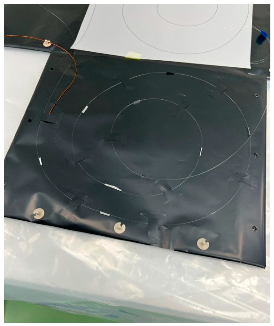
Abstract
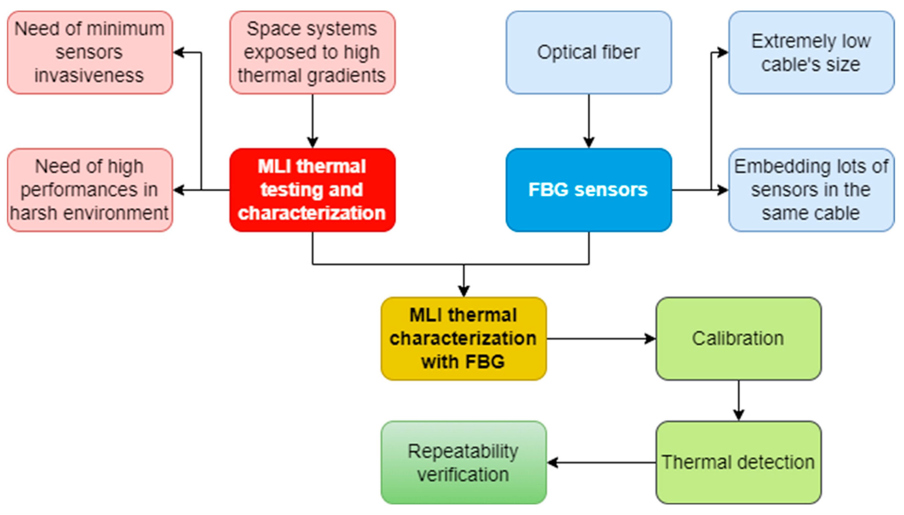
1. Introduction
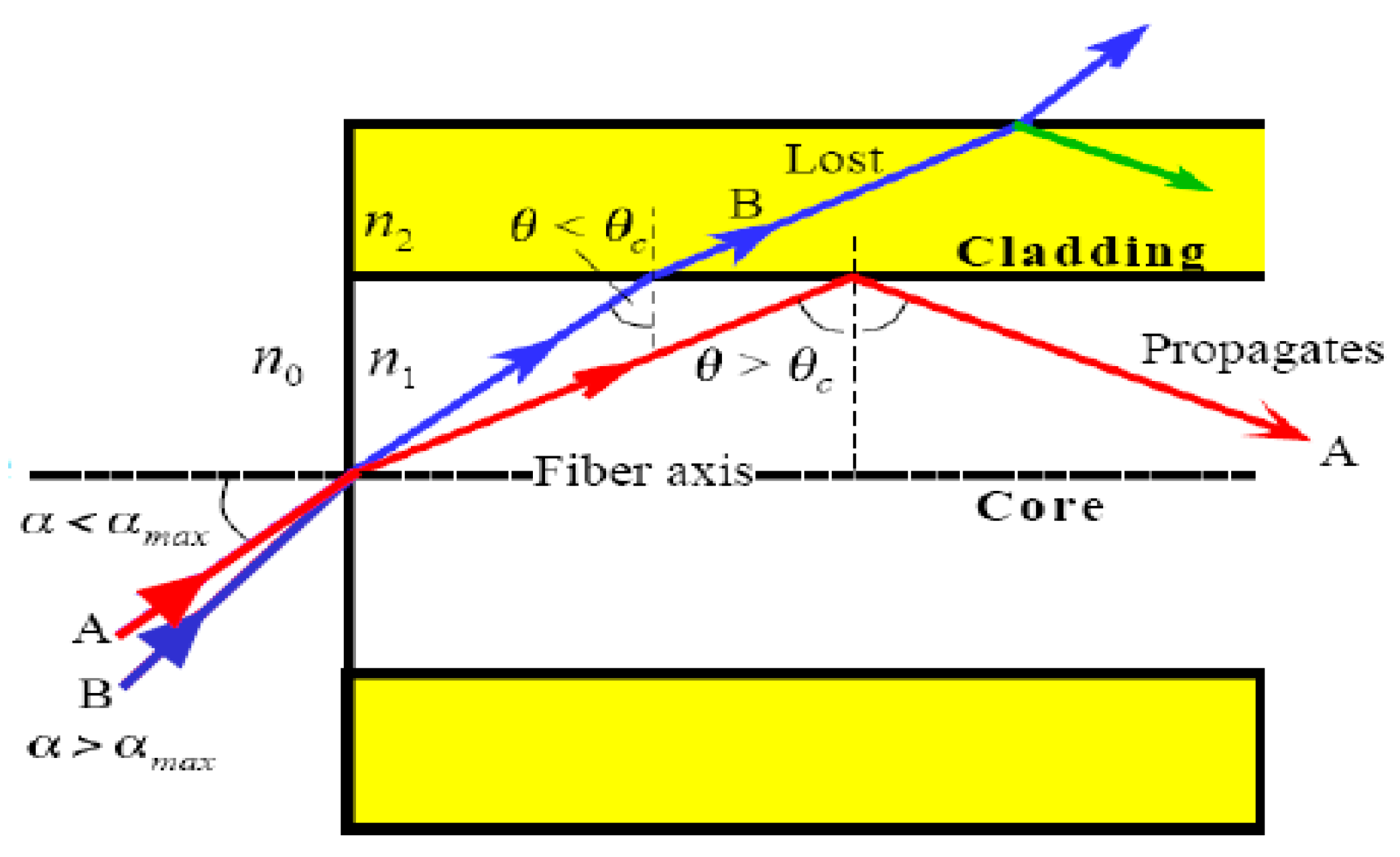
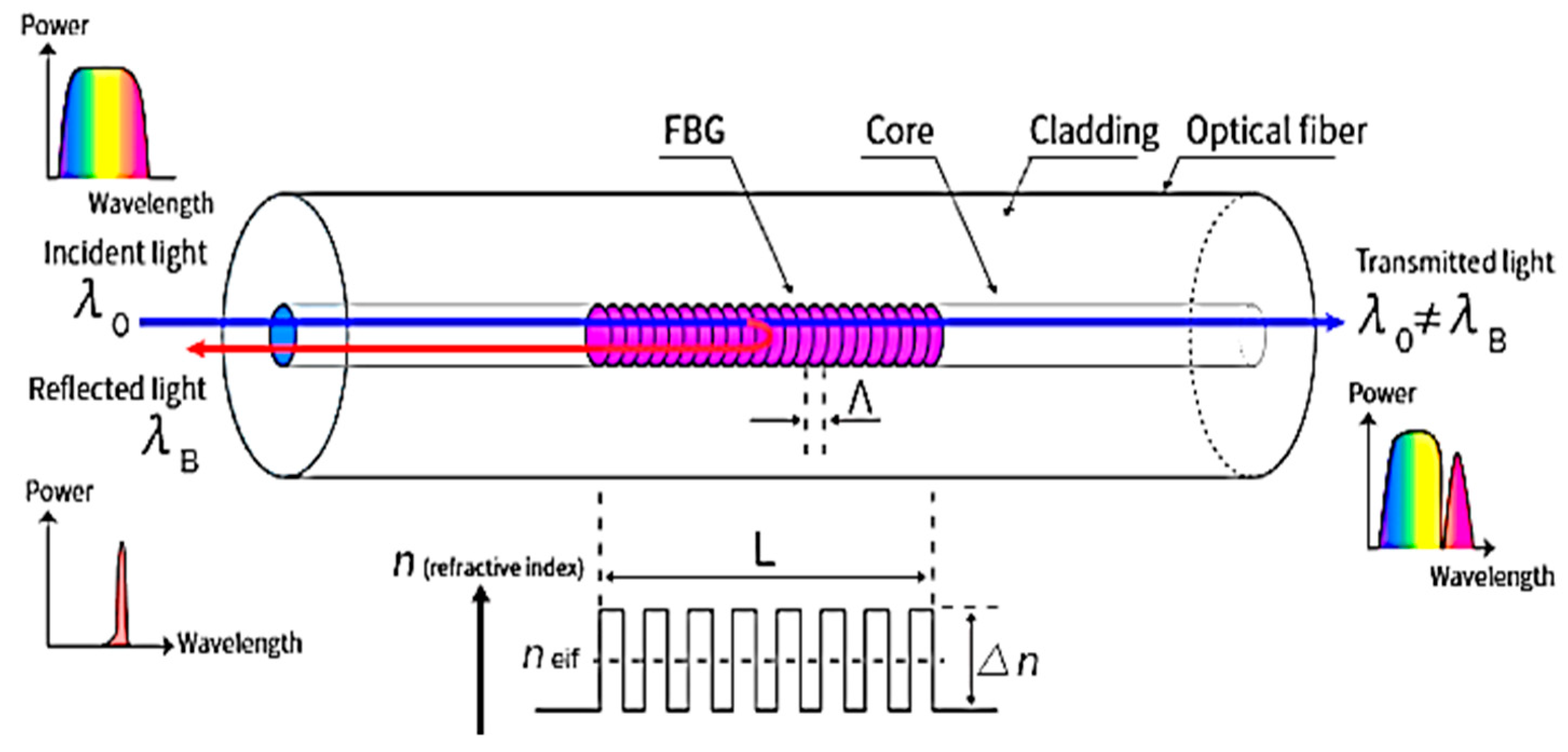
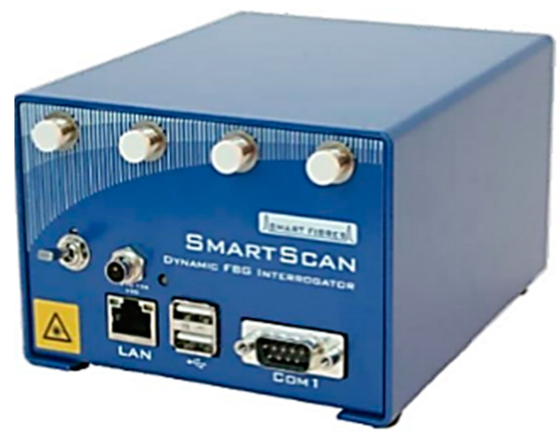
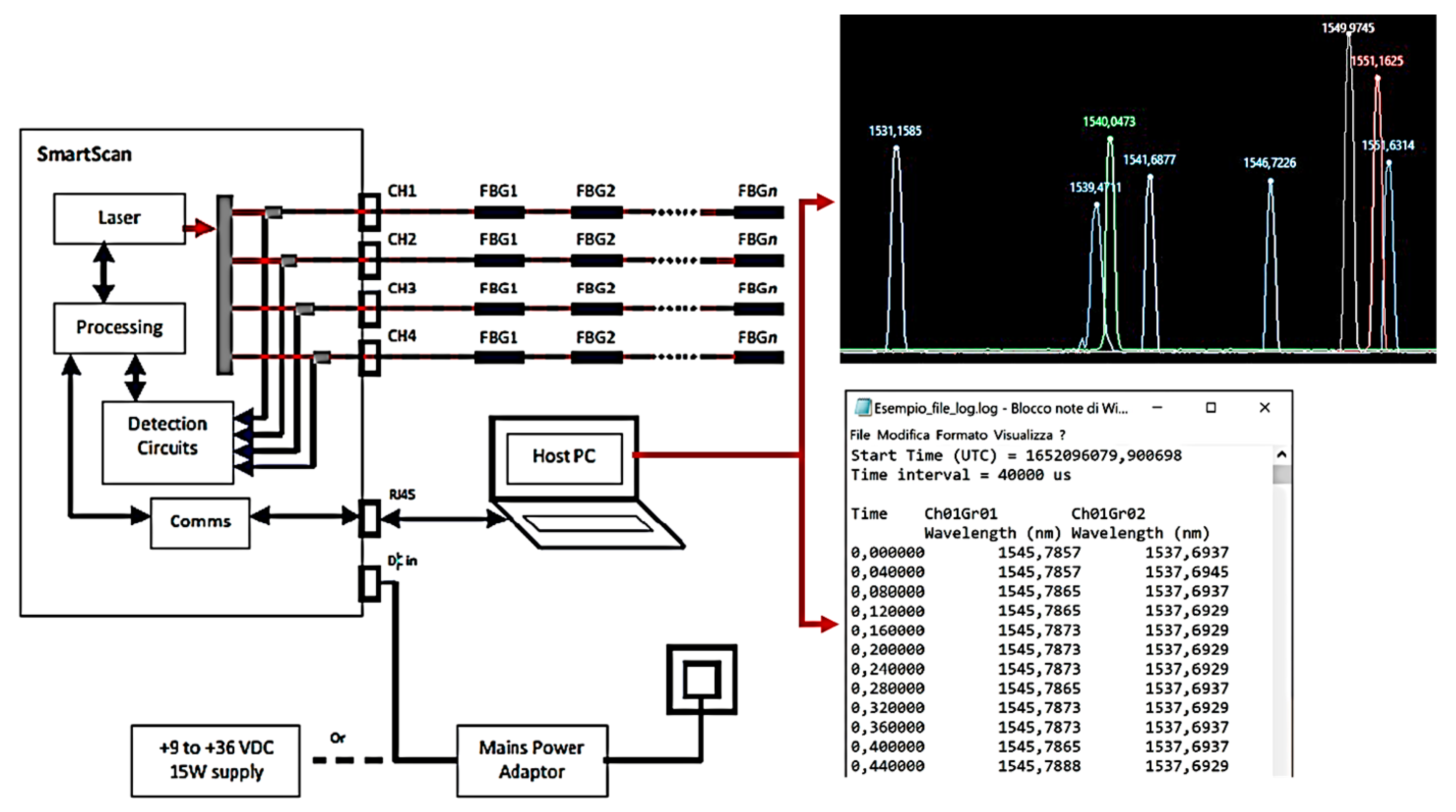
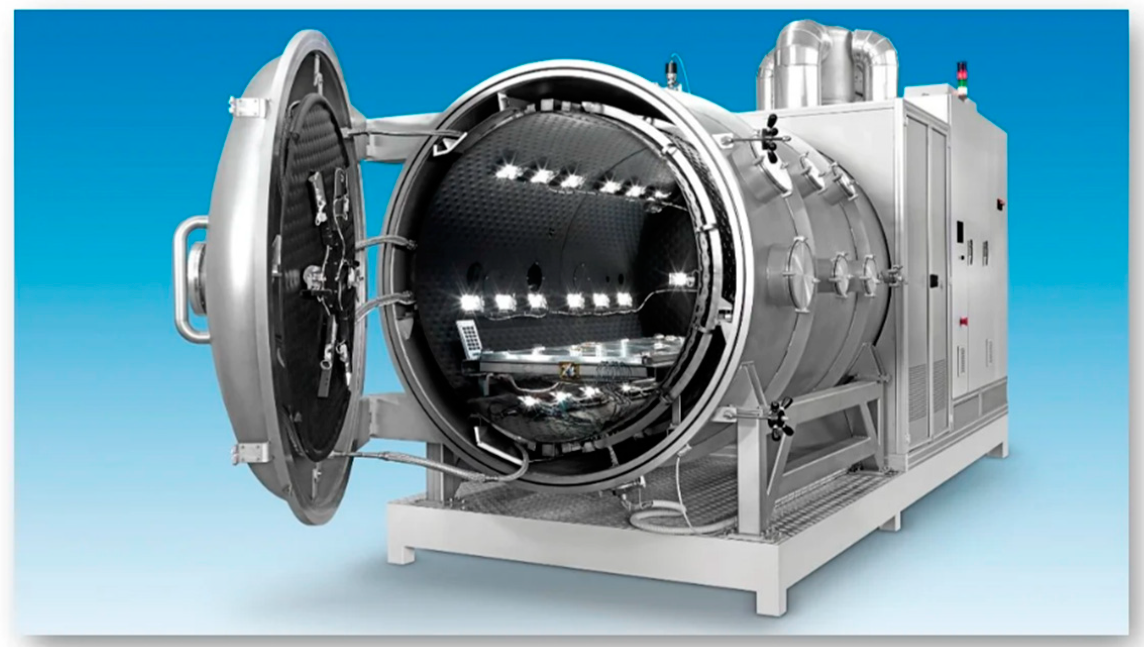
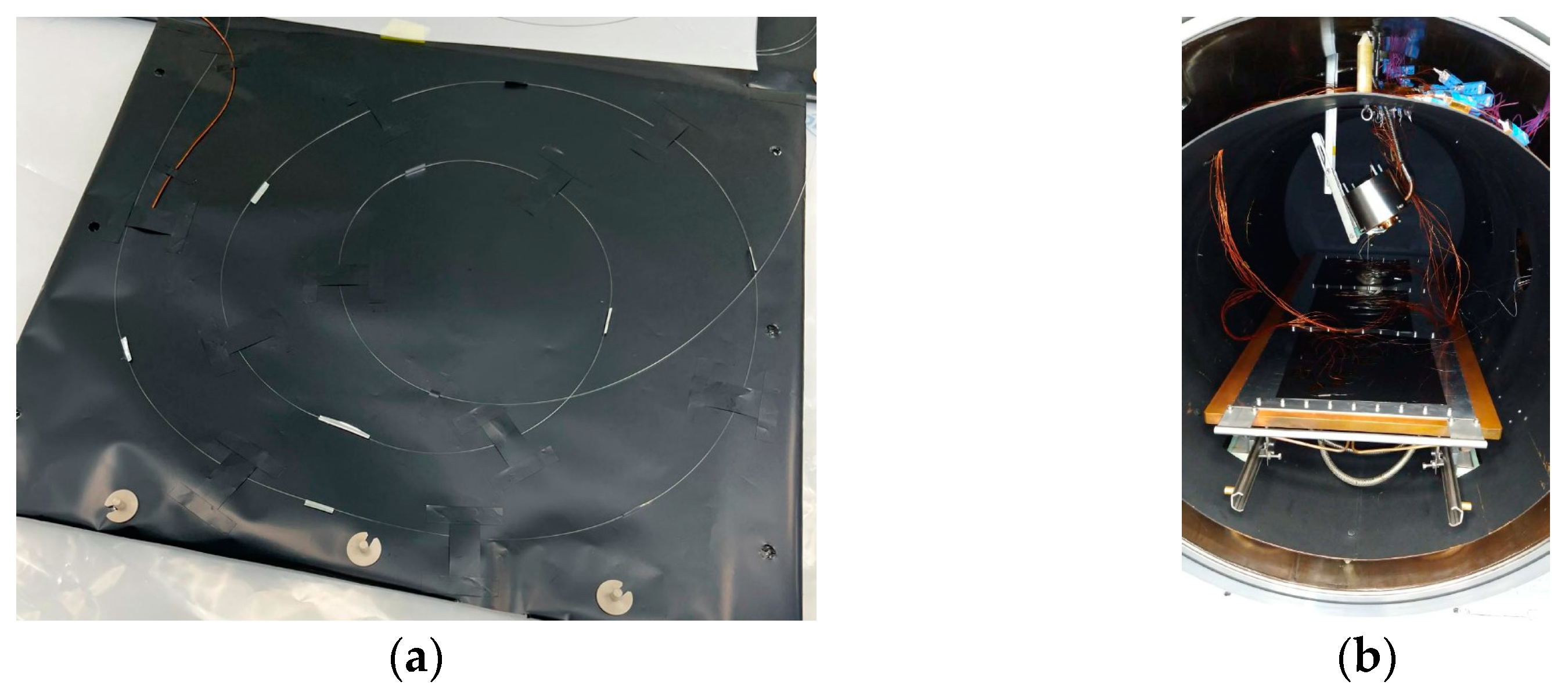
2. Materials and Methods
- Acquiring raw data.
- Calculating the λ(T) curve.
- Converting the FBG output into temperature values.
- Determining the error.
- Collecting raw data.
- Calculating the λ(T) curve.
- Converting the FBG output into temperature values.
- Determining the error.
- Thermal Cycle 1 ranging from 0 °C to 200 °C.
- Thermal Cycle 2 ranging from −150 °C to 200 °C.
- Repeatability and accuracy validation cycle.
3. Results
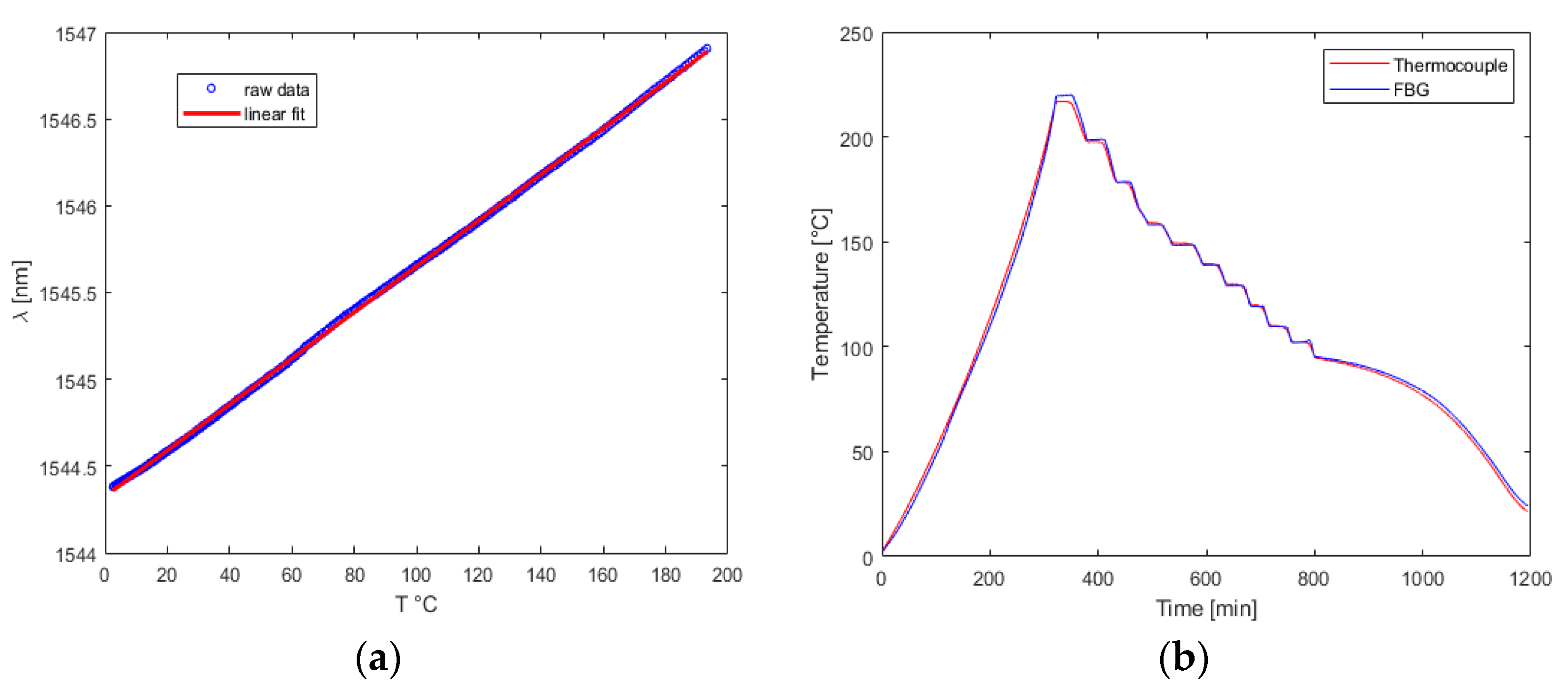
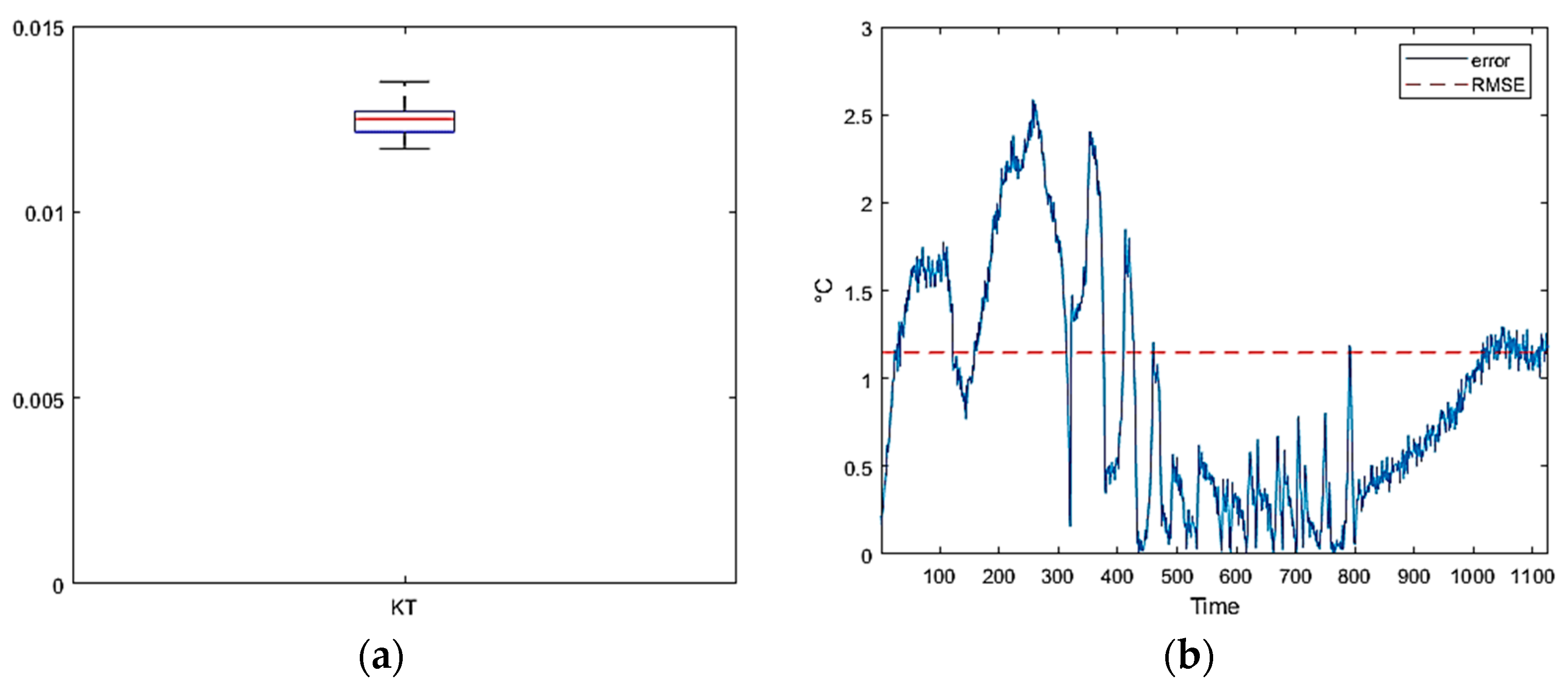
3.1. Thermal Cycle 1: Temperature Range 0 to 200 °C
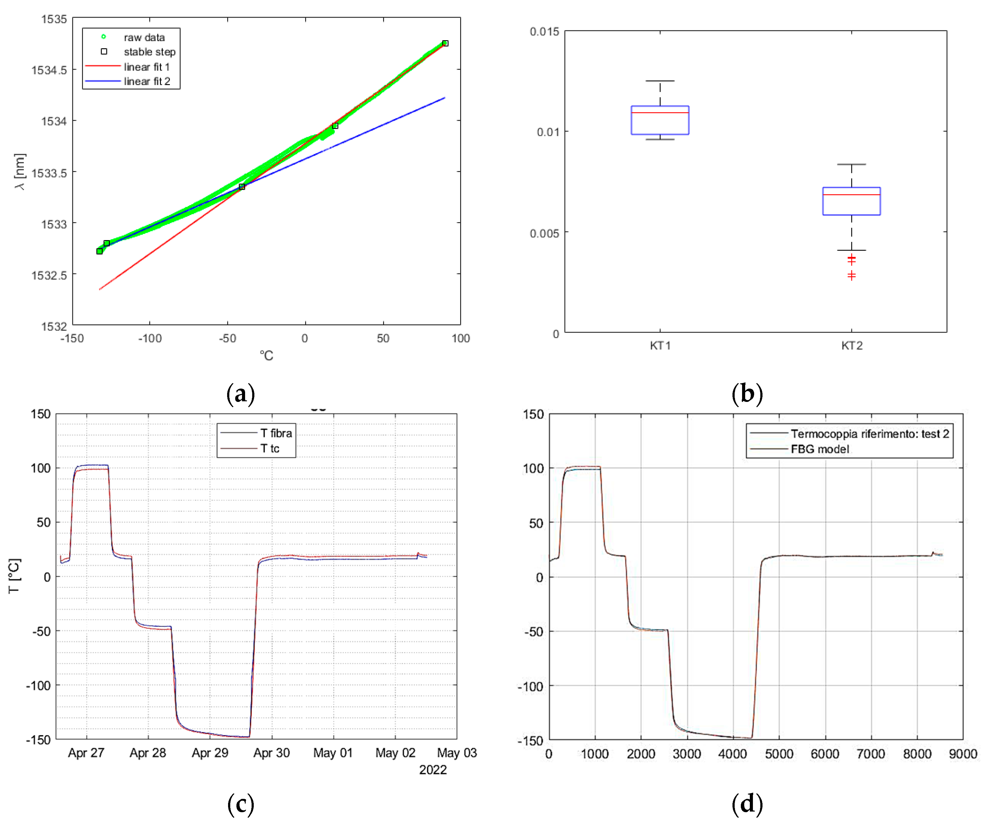
3.2. Tests Cycle 2: Temperature Range −150 to 200 °C
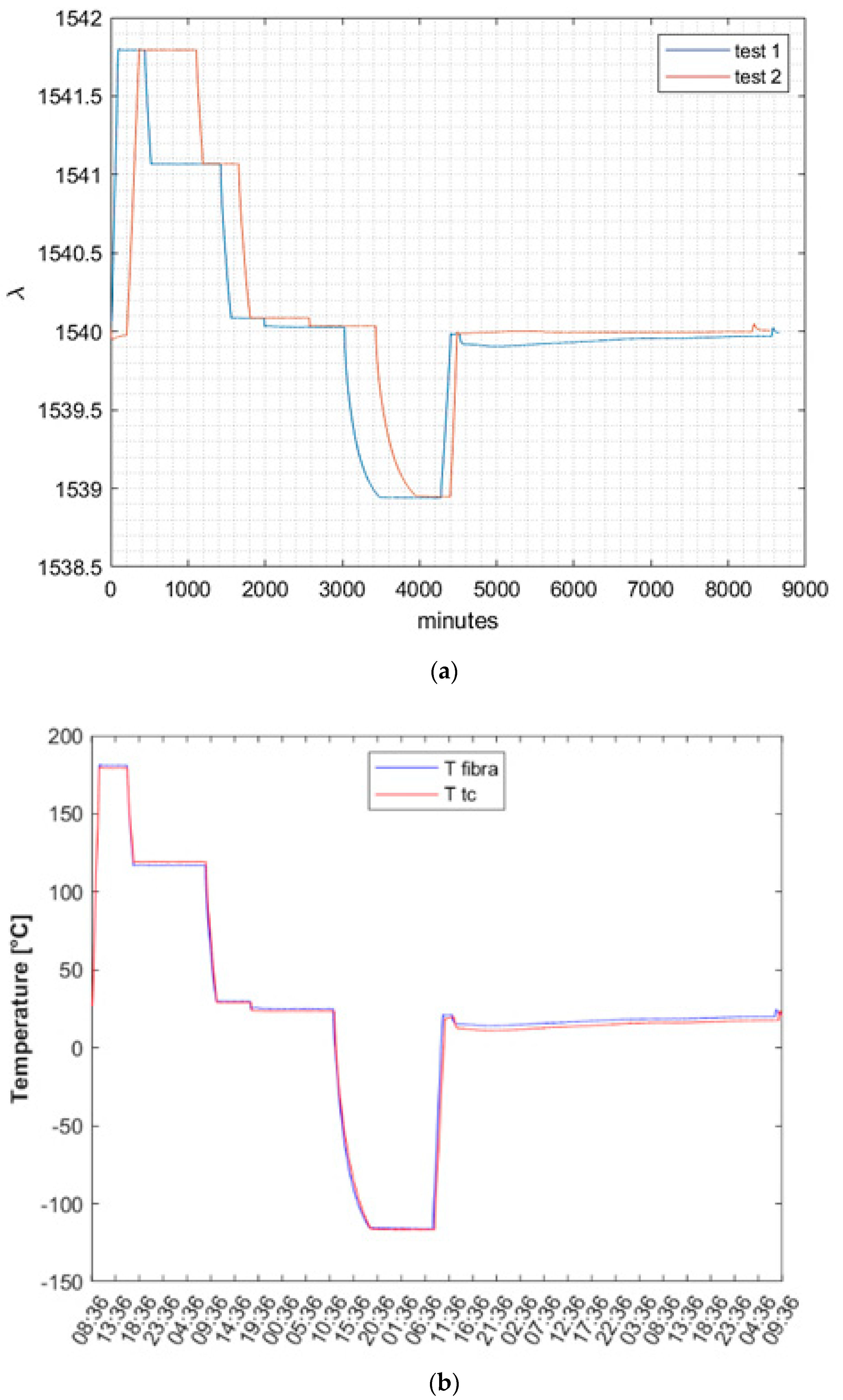
3.3. Repeatability and Accuracy Analysis
4. Discussion
5. Conclusions
Author Contributions
Funding
Acknowledgments
Conflicts of Interest
References
- Pisacane, V.L. Space systems engineering. In The International Handbook of Space Technology; John Wiley & Sons: Hoboken, NJ, USA, 2014. [Google Scholar] [CrossRef]
- Mihailov, S.J. Fiber bragg grating sensors for harsh environments. Sensors 2012, 12, 1898. [Google Scholar] [CrossRef] [PubMed]
- Mihailov, S.J.; Grobnic, D.; Hnatovsky, C.; Walker, R.B.; Lu, P.; Coulas, D.; Ding, H. Extreme Environment Sensing Using Femtosecond Laser-Inscribed Fiber Bragg Gratings. Sensors 2017, 17, 2909. [Google Scholar] [CrossRef] [PubMed]
- Mihailov, S.J.; Hnatovsky, C.; Abdukerim, N.; Walker, R.B.; Lu, P.; Xu, Y.; Bao, X.; Ding, H.; De Silva, M.; Coulas, D.; et al. Ultrafast Laser Processing of Optical Fibers for Sensing Applications. Sensors 2021, 21, 1447. [Google Scholar] [CrossRef] [PubMed]
- Leung, C.K.Y.; Wan, K.T.; Inaudi, D.; Bao, X.; Habel, W.; Zhou, Z.; Ou, J.; Ghandehari, M.; Wu, H.C.; Imai, M. Review: Optical fiber sensors for civil engineering applications. Mater. Struct./Materiaux Constructions 2013, 48, 871–906. [Google Scholar] [CrossRef]
- Tanaka, N.; Okabe, Y.; Takeda, N. Temperature-compensated strain measurement using fiber Bragg grating sensors embedded in composite laminates. Smart Mater. Struct. 2003, 12, 940–946. [Google Scholar] [CrossRef]
- Brusa, E.; Vedova, M.D.; Giorio, L.; Maggiore, P. Thermal condition monitoring of large smart bearing through fiber optic sensors. Mech. Adv. Mater. Struct. 2021, 28, 1187–1193. [Google Scholar] [CrossRef]
- Wang, W.; Yu, Y.; Geng, Y.; Li, X. Measurements of thermo-optic coefficient of standard single mode fiber in large temperature range. In Proceedings of the 2015 International Conference on Optical Instruments and Technology: Optical Sensors and Applications, Beijing, China, 8–10 May 2015. [Google Scholar] [CrossRef]
- McKenzie, I.; Ibrahim, S.; Haddad, E.; Abad, S.; Hurni, A.; Cheng, L.K. Fiber Optic Sensing in Spacecraft Engineering: An Historical Perspective From the European Space Agency. Front. Physics 2021, 9, 719441. [Google Scholar] [CrossRef]
- Selwan, M.F.; Ibrahim, K. Fiber Sensing for Space Applications. In Proceedings of the Conference: ECSSMET 2018, Noordwijk, The Netherlands, 28 May–1 June 2018. [Google Scholar]
- Tosi, D. Review of chirped fiber bragg grating (CFBG) fiber-optic sensors and their applications. Sensors 2018, 18, 2147. [Google Scholar] [CrossRef]
- Allwood, G.; Wild, G.; Hinckley, S. Fiber bragg grating sensors for mainstream industrial processes. Electronics 2017, 6, 92. [Google Scholar] [CrossRef]
- Imbalzano, G.; Linforth, S.; Ngo, T.D.; Lee, P.V.S.; Tran, P. Blast resistance of auxetic and honeycomb sandwich panels: Comparisons and parametric designs. Compos. Struct. 2016, 183, 242–261. [Google Scholar] [CrossRef]
- Hopf, B.; Fischer, B.; Bosselmann, T.; Koch, A.W.; Roths, J. Strain-independent temperature measurements with surface-glued polarization-maintaining fiber bragg grating sensor elements. Sensors 2019, 19, 144. [Google Scholar] [CrossRef] [PubMed]
- Ecke, W.; Latka, I.; Willsch, R.; Reutlinger, A.; Graue, R. Fibre optic sensor network for spacecraft health monitoring. Meas. Sci. Technol. 2001, 12, 974. [Google Scholar] [CrossRef]
- Mesforoush, H.; Pakmanesh, M.R.; Esfandiary, H.; Asghari, S.; Baniasadi, E. Experimental and numerical analyses of thermal performance of a thin-film multi-layer insulation for satellite application. Cryogenics 2019, 102, 77–84. [Google Scholar] [CrossRef]
- Miyakita, T.; Kitamoto, K.; Kinefuchi, K.; Saitoh, M.; Hirai, T.; Sugita, H. Development of a new MLI for orbital cryogenic propulsion systems-Thermal performance under one atmosphere to a vacuum. IOP Conf. Ser. Mater. Sci. Eng. 2019, 502, 012062. [Google Scholar] [CrossRef]
- Shi, D.; Shen, J.; Huang, X.; Zhang, C. Distributed FBG Sensors Apply in Spacecraft Health Monitoring. In Proceedings of the AOPC 2017: Fiber Optic Sensing and Optical Communications, Beijing, China, 4–6 June 2017. [Google Scholar] [CrossRef]
- Haddad, E.; Kruzelecky, R.; Zou, J.; Wong, B.; Mohammad, N.; Thatte, G.; Jamroz, W.; Riendeau, S. Innovative embedded fiber sensor system for spacecraft’s health in situ monitoring. AIP Conf. Proc. 2009, 1087, 463–474. [Google Scholar] [CrossRef]
- Singh, S. A Data-Driven Approach to Cubesat Health Monitoring. Master’s Thesis, California Polytechnic State University, San Luis Obispo, CA, USA, 2017. [Google Scholar]
- Rickman, S.L.; Richards, W.L.; Christiansen, E.L.; Piazza, A.; Pena, F.; Parker, A.R. Micrometeoroid/Orbital Debris (MMOD) Impact Detection and Location Using Fiber Optic Bragg Grating Sensing Technology. Procedia Eng. 2017, 188, 233–240. [Google Scholar] [CrossRef]
- Li, W.; Jiang, M.-S.; Lü, S.-S.; Su, C.-H.; Luo, Y.-X.; Shen, J.-S.; Jia, L. Hypervelocity impact monitoring and location identification on aluminum plate based on FBG sensing system. Optoelectron. Lett. 2020, 16, 306–312. [Google Scholar] [CrossRef]
- Yuan, X.W.; Xiao, Z.M.; Zhang, Y.M. Numerical investigation of fracture behavior by crazing in graphene reinforced polymers. Mech. Adv. Mater. Struct. 2022, 29, 7703–7711. [Google Scholar] [CrossRef]
- Zhang, Y.M.; Xiao, Z.M.; Fan, M. Fatigue Investigation on Railway Wheel Steel with White Etching Layer. Int. J. Steel Struct. 2020, 20, 80–88. [Google Scholar] [CrossRef]
- Zhang, Y.; Xiao, Z.; Luo, J. Fatigue crack growth investigation on offshore pipelines with three-dimensional interacting cracks. Geosci. Front. 2018, 9, 1689–1697. [Google Scholar] [CrossRef]
- Yuan, X.W.; Li, W.G.; Xiao, Z.M.; Zhang, Y.M. Prediction of temperature-dependent transverse strength of carbon fiber reinforced polymer composites by a modified cohesive zone model. Compos. Struct. 2023, 304, 116310. [Google Scholar] [CrossRef]
- Hisham, H.K. Optical Fiber Sensing Technology: Basics, Classifications and Applications. Am. J. Remote Sens. 2018, 6, 1–5. [Google Scholar] [CrossRef]
- Aimasso, A.; Vedova, M.D.L.D.; Maggiore, P.; Quattrocchi, G. Study of FBG-based optical sensors for thermal measurements in aerospace applications. J. Phys. Conf. Series 2022, 2293, 012006. [Google Scholar] [CrossRef]
- Aimasso, A.; Vedova, M.D.L.D.; Maggiore, P. Innovative sensor networks for massive distributed thermal measurements in space applications under different environmental testing conditions. In Proceedings of the 2022 IEEE 9th International Workshop on Metrology for AeroSpace, MetroAeroSpace 2022—Proceedings, Pisa, Italy, 27–29 June 2022. [Google Scholar] [CrossRef]
- Dupont Kapton DuPontTM Kapton®. 2021. Available online: http://www.dupont.com/content/dam/dupont/products-and-services/membranes-and-films/polyimde-films/documents/DEC-Kapton-summary-of-properties.pdf (accessed on 31 January 2023).
- Vedova, M.D.; Berri, P.; Aimasso, A. Environmental sensitivity of fiber Bragg grating sensors for aerospace prognostics. In Proceedings of the 31st European Safety and Reliability Conference (ESREL 2021), Angers, France, 19–23 September 2021. [Google Scholar]
- Filho, E.S.D.L.; Baiad, M.D.; Gagné, M.; Kashyap, R. Fiber Bragg gratings for low-temperature measurement. Opt. Express 2014, 22, 27681. [Google Scholar] [CrossRef]
- Wu, M.-C.; Dehaven, S.L. High-Sensitivity Cryogenic Temperature Sensors Using Pressurized Fiber Bragg Gratings. In Proceedings of the Optical Sensing II, Strasbourg, France, 3–6 April 2006. [Google Scholar]
- De Miguel-Soto, V.; Leandro, D.; Lopez-Aldaba, A.; Beato-López, J.J.; Pérez-Landazábal, J.I.; Auguste, J.-L.; Jamier, R.; Roy, P.; Lopez-Amo, M. Study of optical fiber sensors for cryogenic temperature measurements. Sensors 2017, 17, 2773. [Google Scholar] [CrossRef]


Disclaimer/Publisher’s Note: The statements, opinions and data contained in all publications are solely those of the individual author(s) and contributor(s) and not of MDPI and/or the editor(s). MDPI and/or the editor(s) disclaim responsibility for any injury to people or property resulting from any ideas, methods, instructions or products referred to in the content. |
© 2023 by the authors. Licensee MDPI, Basel, Switzerland. This article is an open access article distributed under the terms and conditions of the Creative Commons Attribution (CC BY) license (https://creativecommons.org/licenses/by/4.0/).
Share and Cite
Aimasso, A.; Ferro, C.G.; Bertone, M.; Dalla Vedova, M.D.L.; Maggiore, P. Fiber Bragg Grating Sensor Networks Enhance the In Situ Real-Time Monitoring Capabilities of MLI Thermal Blankets for Space Applications. Micromachines 2023, 14, 926. https://doi.org/10.3390/mi14050926
Aimasso A, Ferro CG, Bertone M, Dalla Vedova MDL, Maggiore P. Fiber Bragg Grating Sensor Networks Enhance the In Situ Real-Time Monitoring Capabilities of MLI Thermal Blankets for Space Applications. Micromachines. 2023; 14(5):926. https://doi.org/10.3390/mi14050926
Chicago/Turabian StyleAimasso, Alessandro, Carlo Giovanni Ferro, Matteo Bertone, Matteo D. L. Dalla Vedova, and Paolo Maggiore. 2023. "Fiber Bragg Grating Sensor Networks Enhance the In Situ Real-Time Monitoring Capabilities of MLI Thermal Blankets for Space Applications" Micromachines 14, no. 5: 926. https://doi.org/10.3390/mi14050926
APA StyleAimasso, A., Ferro, C. G., Bertone, M., Dalla Vedova, M. D. L., & Maggiore, P. (2023). Fiber Bragg Grating Sensor Networks Enhance the In Situ Real-Time Monitoring Capabilities of MLI Thermal Blankets for Space Applications. Micromachines, 14(5), 926. https://doi.org/10.3390/mi14050926