
Rapid Development of an Injection Mold with High Cooling Performance Using Molding Simulation and Rapid Tooling Technology


Abstract
1. Introduction
2. Experimental Details
3. Results and Discussion
4. Conclusions
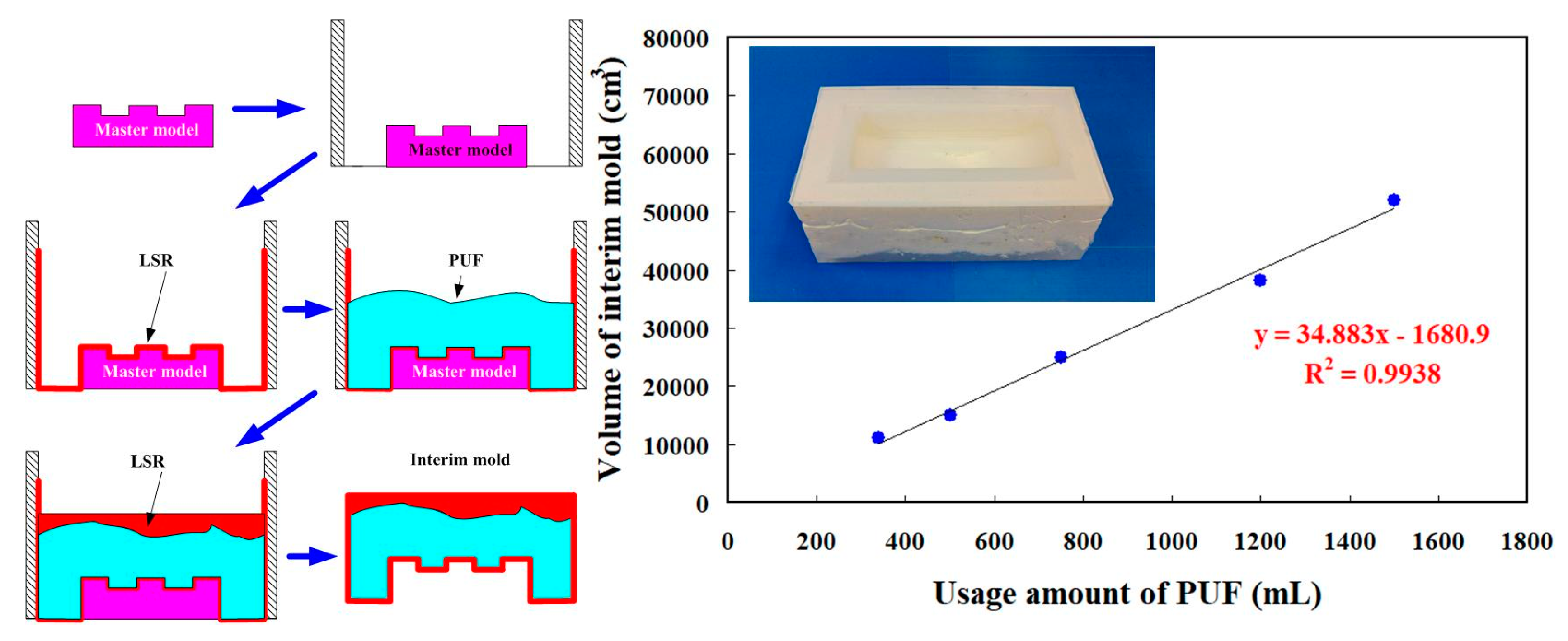
- An innovative method for fabricating a large intermediary mold for a large injection mold using polyurethane foam was proposed. A trend equation for predicting the usage amount of polyurethane foam was demonstrated. Production cost savings of about 50% was obtained.
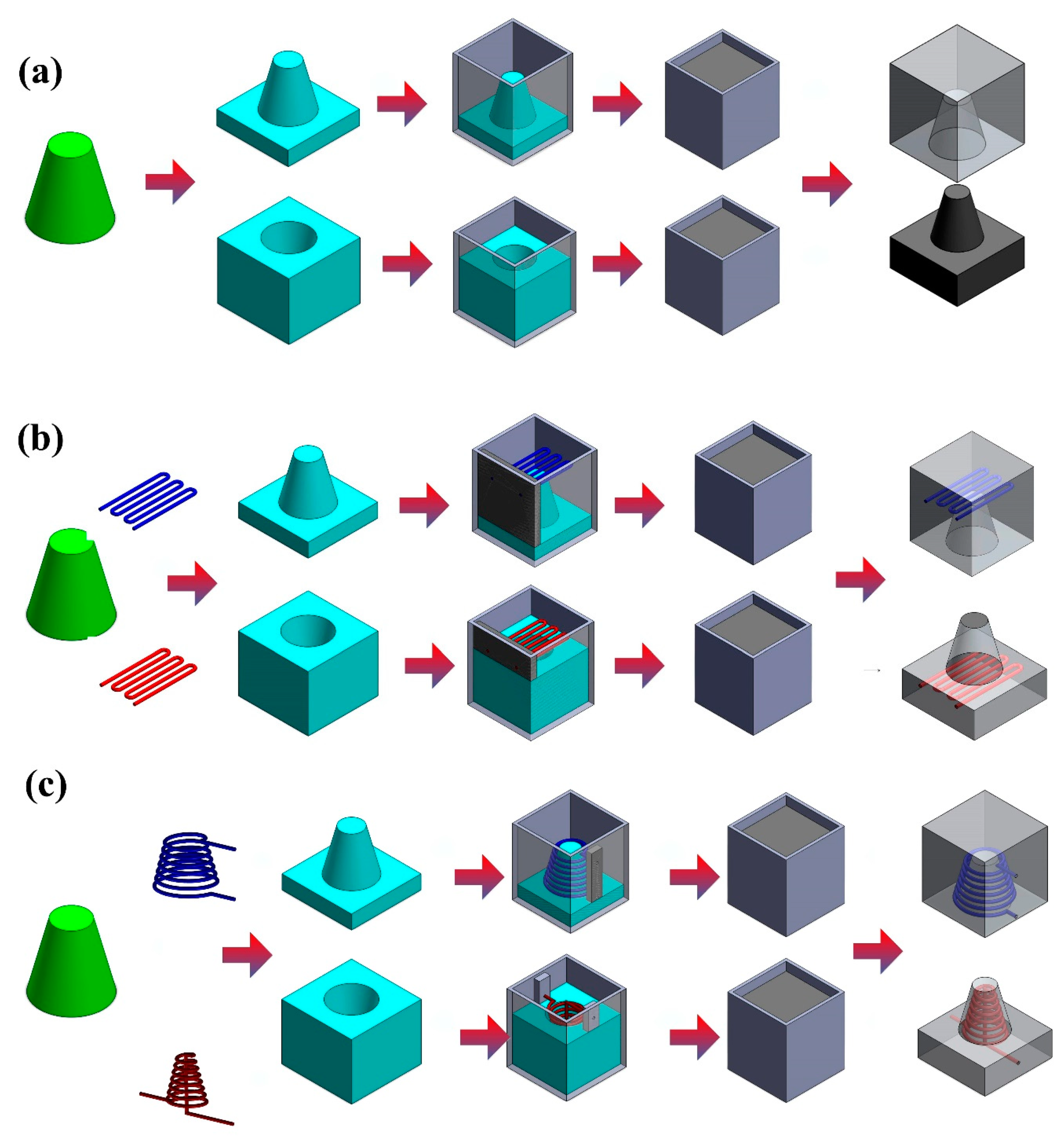
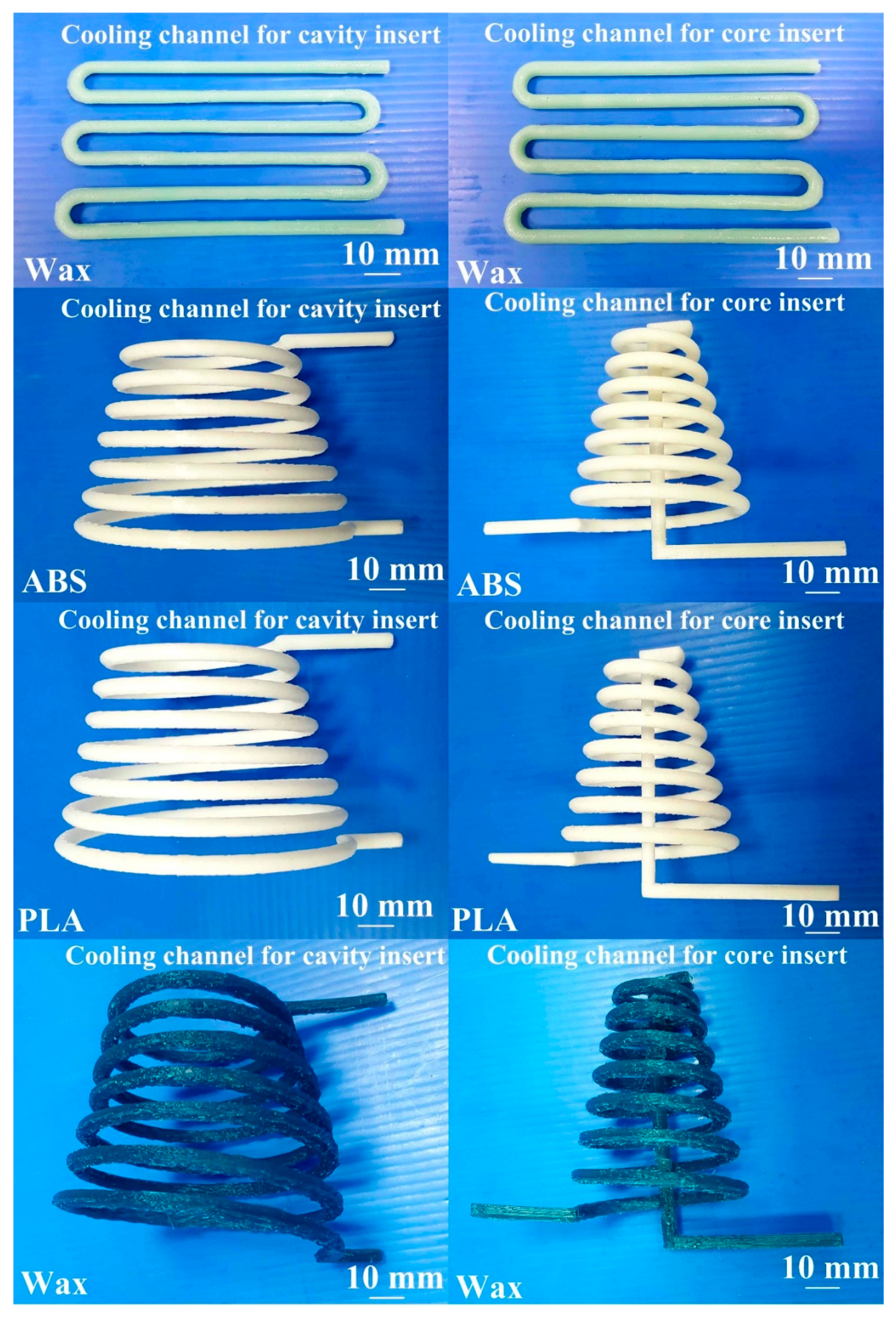
- The wax was found to be a good candidate as the material to fabricate CCCs because it can be removed completely and efficiently.
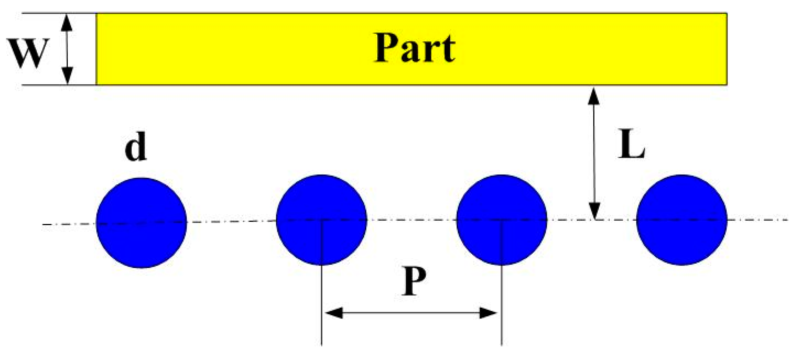
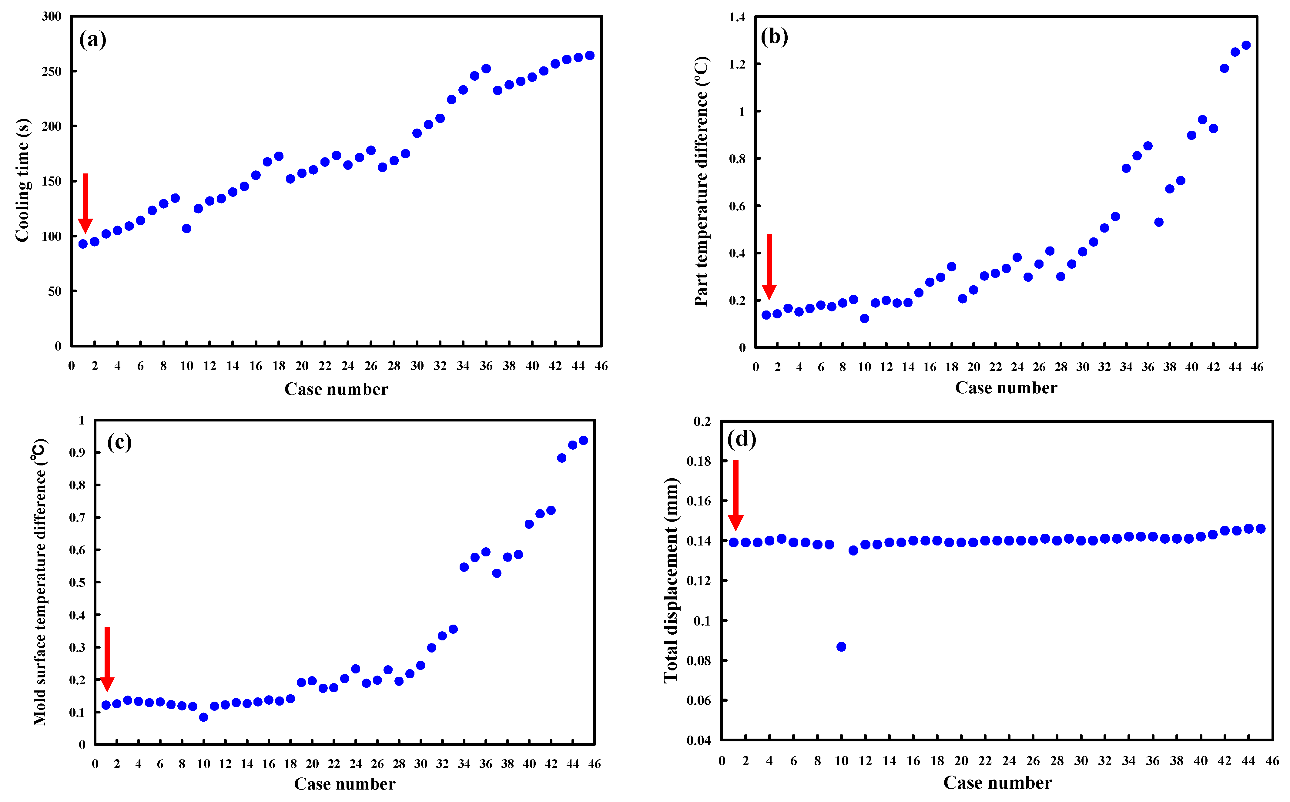
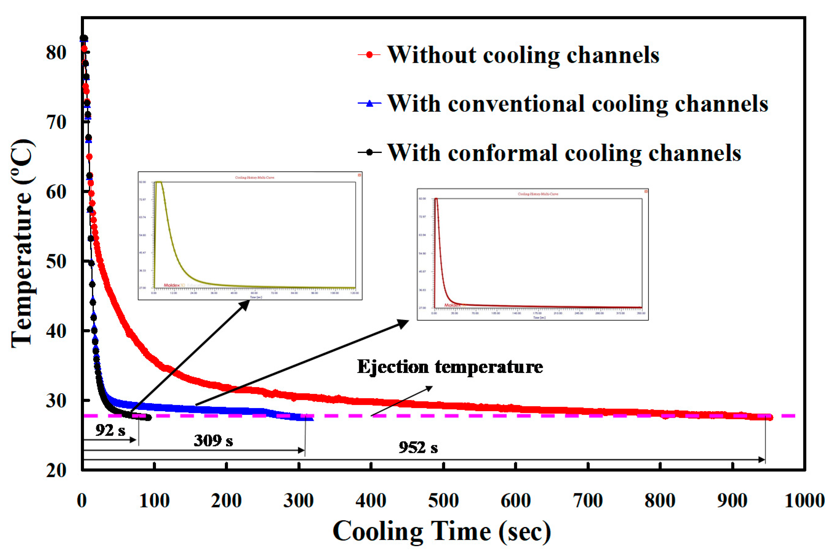
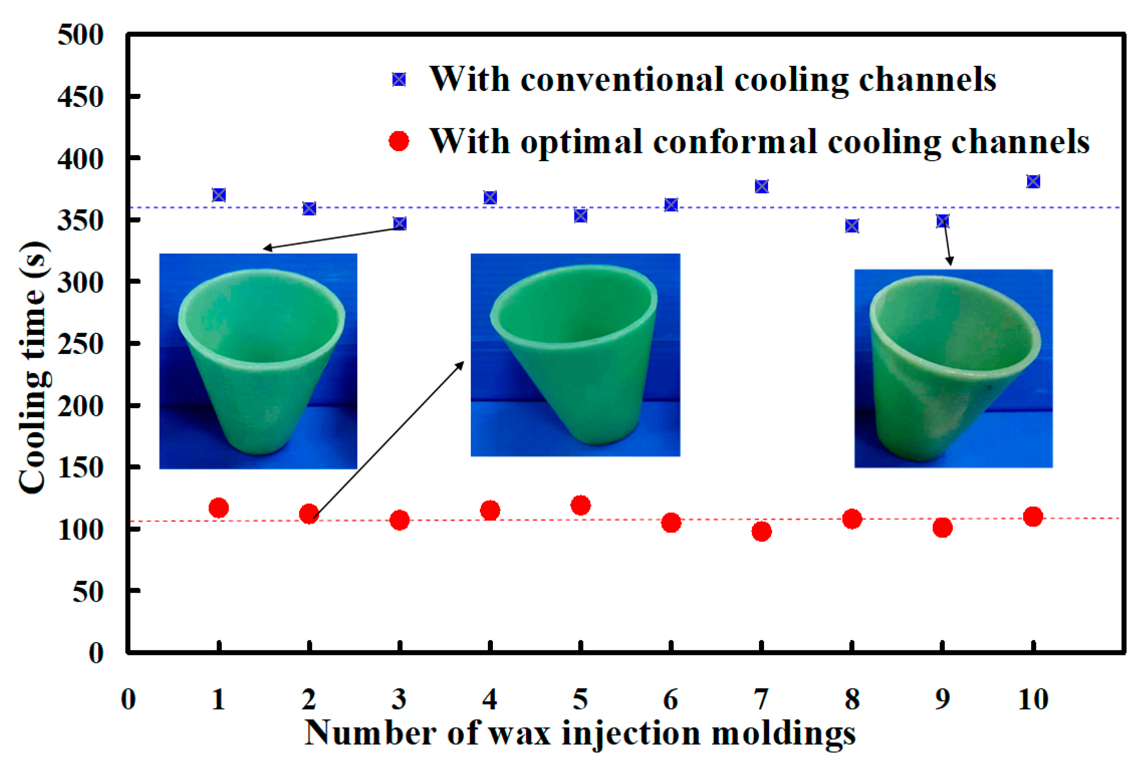
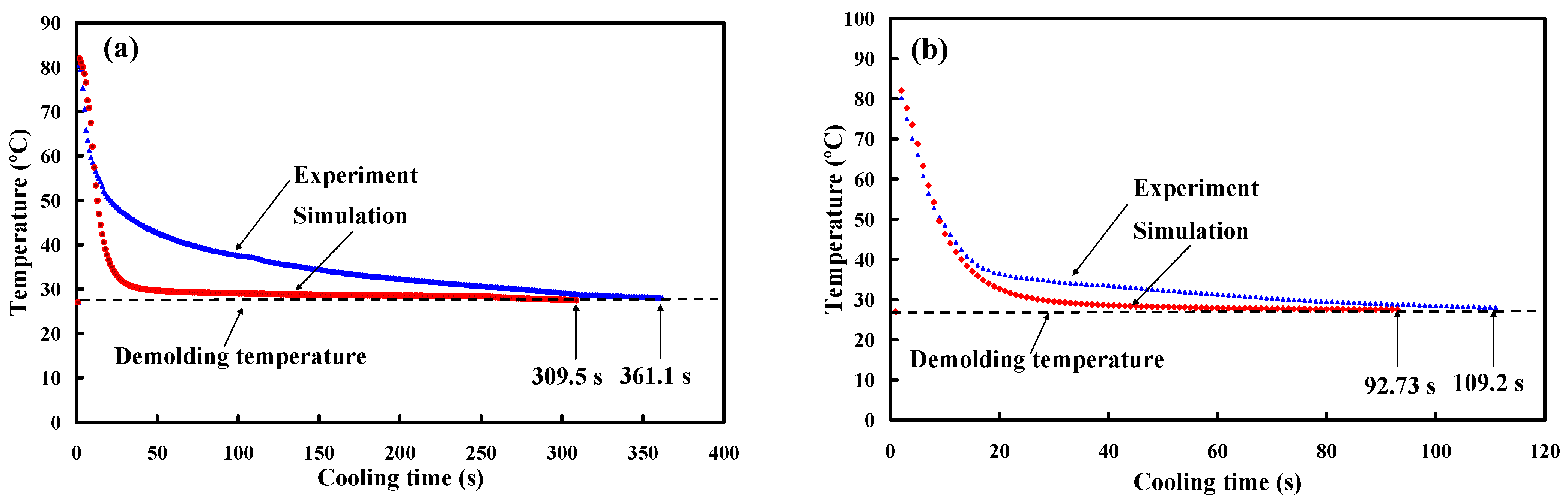
- In an optimum conformal cooling channel design, the cooling channel diameter, center distance between cooling channels, and center distance with respect to mold cavity were 4, 6, and 8 mm, respectively. A reduction in the cooling time of about 89% can be obtained when the optimum CCCs were used in the injection mold. The variation of the results between the experiment and the simulation was approximately 15.1%.
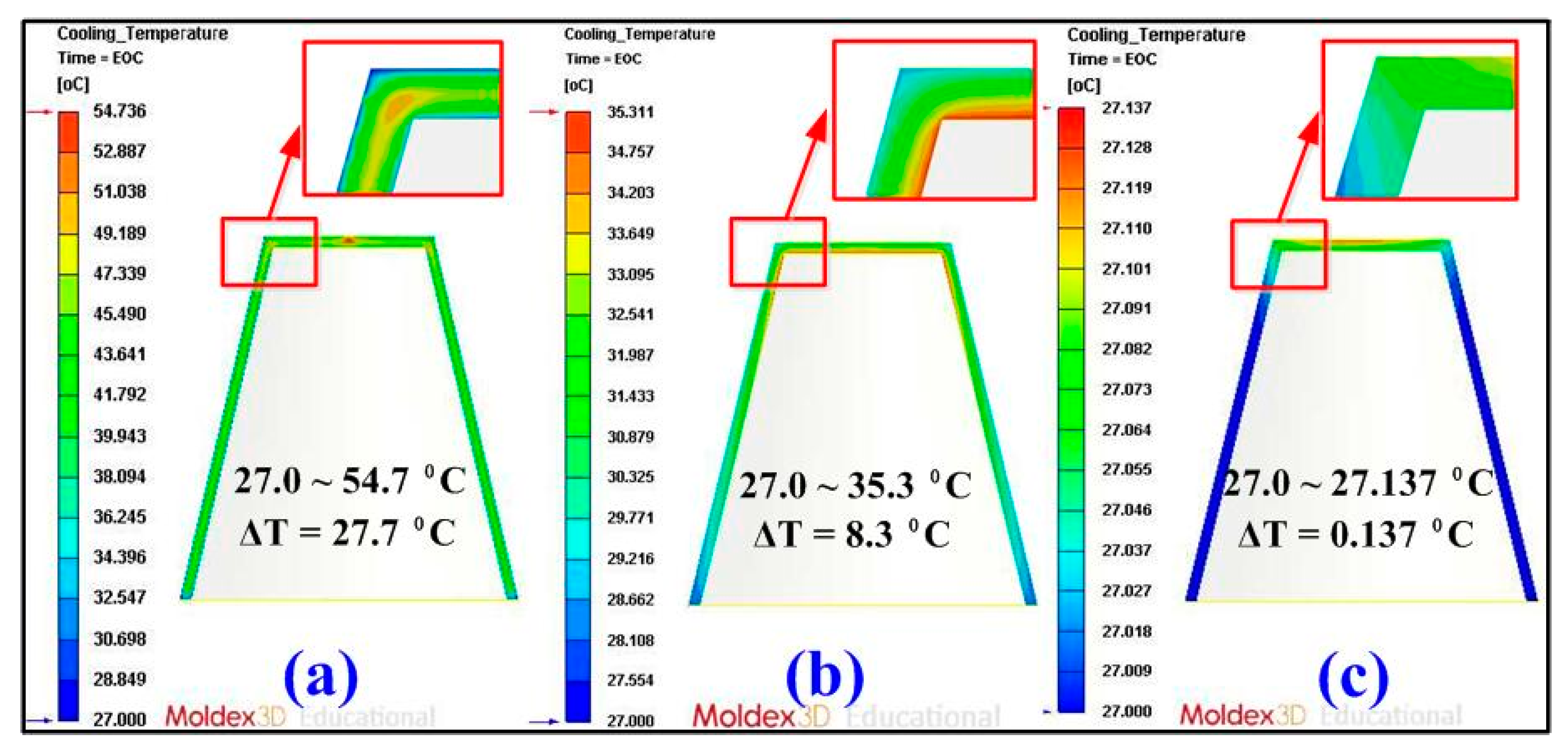
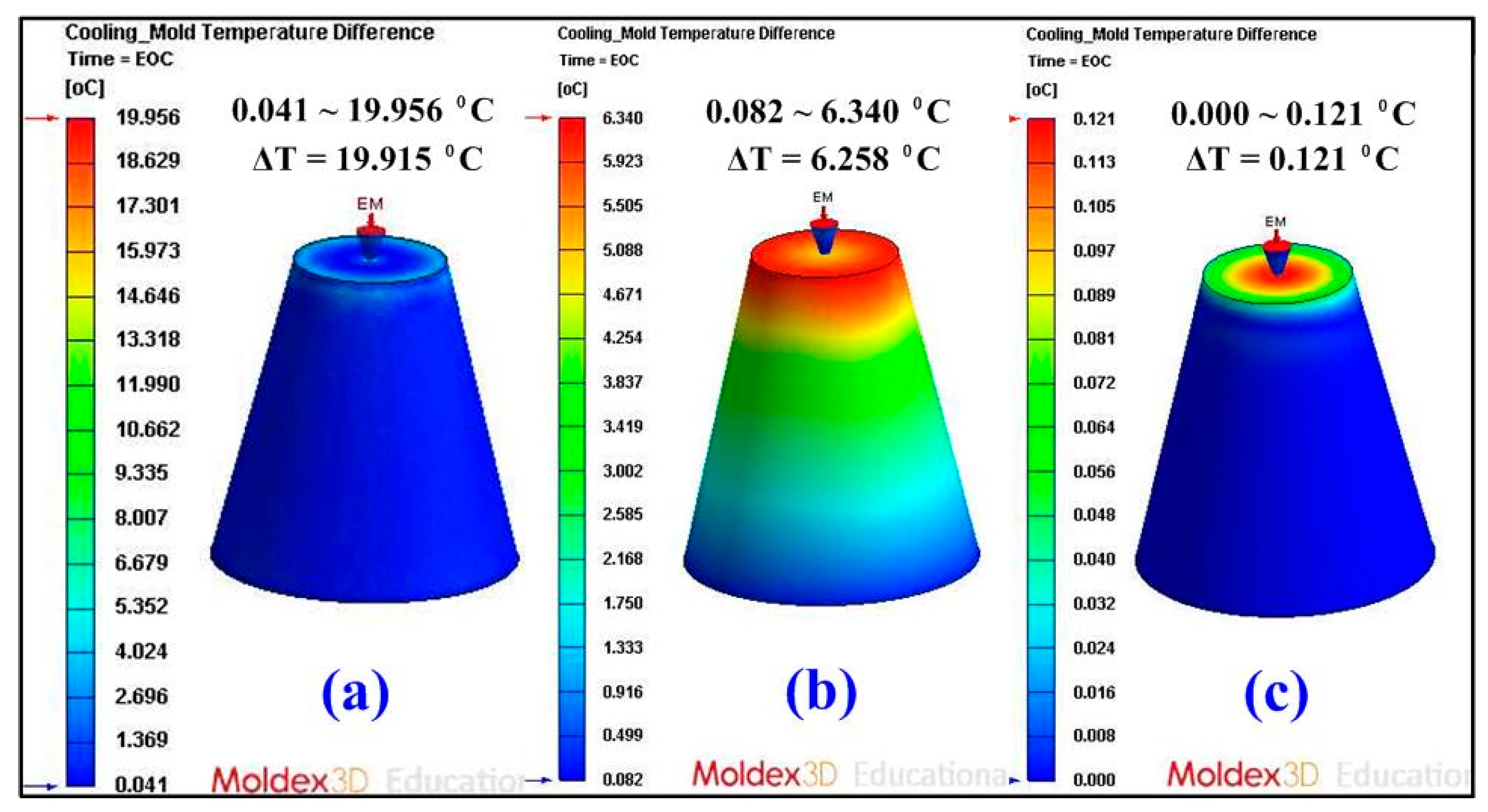
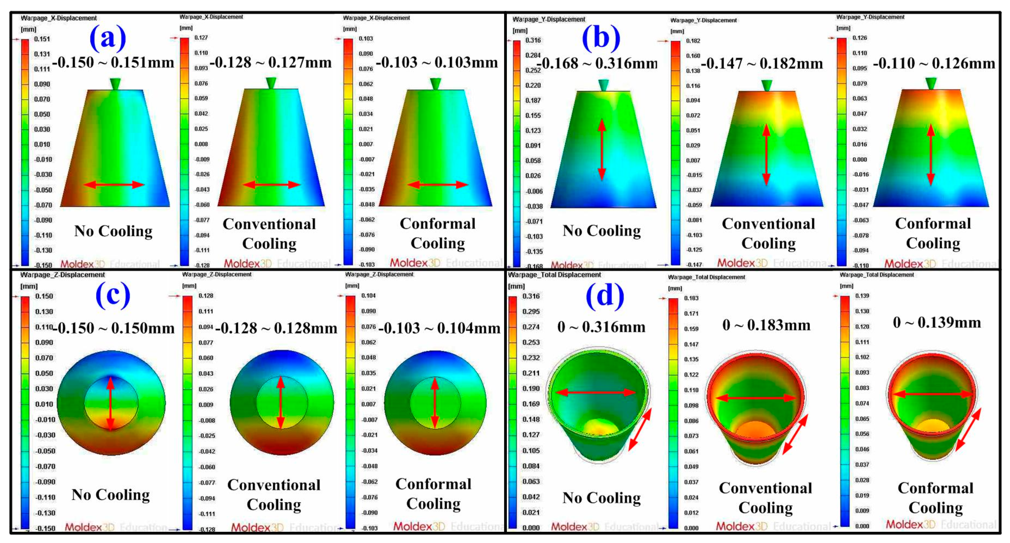
- The benefits of the simulation in the cooling time, part temperature difference, mold surface temperature difference, and product total deformation were 47.28, 72.01, 72.9, and 38.22%, respectively.
Author Contributions
Funding
Institutional Review Board Statement
Informed Consent Statement
Data Availability Statement
Conflicts of Interest
References
- Woo, S.W.; Jo, Y.K.; Yoo, Y.E.; Kim, S.K. High-Throughput Synthesis of Liposome Using an Injection-Molded Plastic Micro-Fluidic Device. Micromachines 2021, 12, 170. [Google Scholar] [CrossRef] [PubMed]
- Scharowsky, T.; Bauereib, A.; Korner, C. Influence of the hatching strategy on consolidation during selective electron beam melting of Ti-6Al-4V. Int. J. Adv. Manuf. Technol. 2017, 92, 2809–2818. [Google Scholar] [CrossRef]
- Liu, Y.; Yang, Y.; Wang, D. A study on the residual stress during selective laser melting (SLM) of metallic powder. Int. J. Adv. Manuf. Technol. 2016, 87, 647–656. [Google Scholar] [CrossRef]
- Leite, J.L.; Salmoria, G.V.; Paggi, R.A.; Ahrens, C.H.; Pouzada, A.S. Microstructural characterization and mechanical properties of functionally graded PA12/HDPE parts by selective laser sintering. Int. J. Adv. Manuf. Technol. 2012, 59, 583–591. [Google Scholar] [CrossRef]
- Lin, H.; Luo, H.; Huang, W.; Zhang, X.; Yao, G. Diffusion bonding in fabrication of aluminum foam sandwich panels. J. Mater. Process. Technol. 2016, 230, 35–41. [Google Scholar] [CrossRef]
- AGorunov, A.I.; Gilmutdinov, A.K. Study of the effect of heat treatment on the structure and properties of the specimens obtained by the method of direct metal deposition. Int. J. Adv. Manuf. Technol. 2016, 86, 2567–2574. [Google Scholar] [CrossRef]
- AlMangour, B.; Yang, J.M. Understanding the deformation behavior of 17-4 precipitate hardenable stainless steel produced by direct metal laser sintering using micropillar compression and TEM. Int. J. Adv. Manuf. Technol. 2017, 90, 119–126. [Google Scholar] [CrossRef]
- Kitayama, S.; Miyakawa, H.; Takano, M.; Aiba, S. Multi-objective optimization of injection molding process parameters for short cycle time and warpage reduction using conformal cooling channel. Int. J. Adv. Manuf. Technol. 2017, 88, 1735–1744. [Google Scholar] [CrossRef]
- Holker, R.; Tekkaya, A.E. Advancements in the manufacturing of dies for hot aluminum extrusion with conformal cooling channels. Int. J. Adv. Manuf. Technol. 2016, 83, 1209–1220. [Google Scholar] [CrossRef]
- Lim, W.S.; Choi, H.S.; Ahn, S.Y.; Kim, B.M. Cooling channel design of hot stamping tools for uniform high-strength components in hot stamping process. Int. J. Adv. Manuf. Technol. 2014, 70, 1189–1203. [Google Scholar] [CrossRef]
- Wang, X.; Li, Z.; Gu, J.; Ruan, S.; Shen, C.; Wang, X. Reducing service stress of the injection-molded polycarbonate window by optimizing mold construction and product structure. Int. J. Adv. Manuf. Technol. 2016, 86, 1691–1704. [Google Scholar] [CrossRef]
- Brooks, H.; Brigden, K. Design of conformal cooling layers with self-supporting lattices for additively manufactured tooling. Addit. Manuf. 2016, 11, 16–22. [Google Scholar] [CrossRef]
- Vojnova, E. The Benefits of a Conforming Cooling Systems the Molds in Injection Moulding Process. Procedia Eng. 2016, 149, 535–543. [Google Scholar] [CrossRef]
- Kuo, C.C.; Chen, W.H.; Zhang, J.W.; Tsai, D.A.; Cao, Y.L. A new method of manufacturing a rapid tooling with different cross-sectional cooling channels. Int. J. Adv. Manuf. Technol. 2017, 92, 3481–3487. [Google Scholar] [CrossRef]
- Kuo, C.C.; You, Z.Y. Development of injection molding tooling with conformal cooling channels fabricated by optimum process parameters. Int. J. Adv. Manuf. Technol. 2018, 96, 1003–1013. [Google Scholar] [CrossRef]
- Kuo, C.C.; Chen, W.H.; Xu, W.C. A cost-effective approach for rapid manufacturing wax injection molds with complex geometrical shapes of cooling channels. Int. J. Adv. Manuf. Technol. 2017, 91, 1689–1695. [Google Scholar] [CrossRef]
- Kuo, C.C.; Chen, W.H.; Liu, X.Z.; Liao, Y.L.; Chen, W.J.; Huang, B.Y.; Tsai, R.L. Development of a low-cost wax injection mold with high cooling efficiency. Int. J. Adv. Manuf. Technol. 2017, 93, 2081–2088. [Google Scholar] [CrossRef]
- Kuo, C.C.; Chen, B.C. Development of hot embossing stamps with conformal cooling channels for microreplication. Int. J. Adv. Manuf. Technol. 2017, 88, 2603–2608. [Google Scholar] [CrossRef]
- Hsu, F.H.; Wang, K.; Huang, C.T.; Chang, R.Y. Investigation on conformal cooling system design in injection molding. Adv. Prod. Eng. Manag. 2013, 8, 107–115. [Google Scholar] [CrossRef]
- Jahan, S.A.; Wu, T.; Zhang, Y.; El-Mounayri, H.; Tovar, A.; Zhang, J.; Lee, W.H. Implementation of Conformal Cooling & Topology Optimization in 3D Printed Stainless Steel Porous Structure Injection Molds. Procedia Manuf. 2016, 5, 901–915. [Google Scholar]
- Wang, Y.; Yu, K.M.; Wang, C.C.L.; Zhang, Y. Automatic design of conformal cooling circuits for rapid tooling. Comput. Aided Des. 2011, 43, 1001–1010. [Google Scholar] [CrossRef]
- Park, H.S.; Pham, N.H. Design of conformal cooling channels for an automotive part. Int. J. Automot. Technol. 2009, 10, 87–93. [Google Scholar] [CrossRef]
- Kitayama, S.; Yokoyama, M.; Takano, M.; Aiba, S. Multi-objective optimization of variable packing pressure profile and process parameters in plastic injection molding for minimizing warpage and cycle time. Int. J. Adv. Manuf. Technol. 2017, 92, 3991–3999. [Google Scholar] [CrossRef]
- Oktem, H. Optimum process conditions on shrinkage of an injected-injection molded part of DVD-ROM cover using Taguchi robust method. Int. J. Adv. Manuf. Technol. 2012, 61, 519–528. [Google Scholar] [CrossRef]
- Guo, W.; Hua, L.; Mao, H. Minimization of sink mark depth in injection-molded thermoplastic through design of experiments and genetic algorithm. Int. J. Adv. Manuf. Technol. 2014, 72, 365–375. [Google Scholar] [CrossRef]
- Liu, C.; Cai, Z.; Dai, Y.; Huang, N.; Xu, F.; Lao, C. Experimental comparison of the flow rate and cooling performance of internal cooling channels fabricated via selective laser melting and conventional drilling process. Int. J. Adv. Manuf. Technol. 2018, 96, 2757–2767. [Google Scholar] [CrossRef]
- Matos, M.A.; Rocha, A.M.A.C.; Pereira, A.I. Improving additive manufacturing performance by build orientation optimization. Int. J. Adv. Manuf. Technol. 2020, 107, 1993–2005. [Google Scholar] [CrossRef]
- Kuo, C.C.; Wu, J.Q. Development of a low-cost epoxy resin mold with high cooling efficiency. Int. J. Adv. Manuf. Technol. 2021, 1–12. [Google Scholar] [CrossRef]
- Kuo, C.C.; You, Z.Y.; Chang, S.J.; Liao, J.D.; Yu, S.T.; Zeng, R.T. Development of green conformal cooling channels for rapid tooling. Int. J. Adv. Manuf. Technol. 2020, 111, 109–125. [Google Scholar] [CrossRef]
- Kuo, C.C.; Zhu, Y.J.; Wu, Y.Z.; You, Z.Y. Development and application of a large injection mold with conformal cooling channels. Int. J. Adv. Manuf. Technol. 2019, 103, 689–701. [Google Scholar] [CrossRef]
- Kuo, C.C.; You, Z.Y.; Wu, J.Y.; Huang, J.L. Development and application of a conformal cooling channel with easy removal and smooth surfaces. Int. J. Adv. Manuf. Technol. 2019, 102, 2029–2039. [Google Scholar] [CrossRef]
- Asgharzadeh, A.; Tiji, S.A.N.; Esmaeilpour, R.; Park, T.; Pourboghrat, F. Determination of hardness-strength and -flow behavior relationships in bulged aluminum alloys and verification by FE analysis on Rockwell hardness test. Int. J. Adv. Manuf. Technol. 2020, 106, 315–331. [Google Scholar] [CrossRef]
- Wollmann, J.; Dolny, A.; Kaszuba, M.; Gronostajski, Z.; Gude, M. Methods for determination of low-cycle properties from monotonic tensile tests of 1.2344 steel applied for hot forging dies. Int. J. Adv. Manuf. Technol. 2019, 102, 3357–3367. [Google Scholar] [CrossRef]
- Yu, H.; Lyu, Y.; Wang, J. Green manufacturing with a bionic surface structured grinding wheel-specific energy analysis. Int. J. Adv. Manuf. Technol. 2019, 104, 2999–3005. [Google Scholar] [CrossRef]
- Li, K.; Zhou, T.; Liu, B. Internet-based intelligent and sustainable manufacturing: Developments and challenges. Int. J. Adv. Manuf. Technol. 2020, 108, 1767–1791. [Google Scholar] [CrossRef]
- Wang, X.; Chen, L.; Dan, B.; Wang, F. Evaluation of EDM process for green manufacturing. Int. J. Adv. Manuf. Technol. 2018, 94, 633–641. [Google Scholar] [CrossRef]
- Gaha, R.; Yannou, B.; Benamara, A. Selection of a green manufacturing process based on CAD features. Int. J. Adv. Manuf. Technol. 2016, 87, 1335–1343. [Google Scholar] [CrossRef]
- Tang, S.; Fan, Z.; Zhao, H.; Yang, L.; Liu, F.; Liu, X. Layered extrusion forming—a simple and green method for additive manufacturing ceramic core. Int. J. Adv. Manuf. Technol. 2018, 96, 3809–3819. [Google Scholar] [CrossRef]
- Zhang, S.; Xu, Z.; Wang, Z. Numerical modeling and simulation of water cooling-controlled solidification for aluminum alloy investment casting. Int. J. Adv. Manuf. Technol. 2017, 91, 763–770. [Google Scholar] [CrossRef]
- Liu, F.; Fan, Z.; Liu, X.; He, J.; Li, F. Aqueous gel casting of water-soluble calcia-based ceramic core for investment casting using epoxy resin as a binder. Int. J. Adv. Manuf. Technol. 2016, 86, 1235–1242. [Google Scholar] [CrossRef]
- Adnan, M.F.; Abdullah, A.B.; Samad, Z. Springback behavior of AA6061 with non-uniform thickness section using Taguchi Method. Int. J. Adv. Manuf. Technol. 2017, 89, 2041–2052. [Google Scholar] [CrossRef]
- Pinar, A.M.; Filiz, S.; Ünlü, B.S. A comparison of cooling methods in the pocket milling of AA5083-H36 alloy via Taguchi method. Int. J. Adv. Manuf. Technol. 2016, 83, 1431–1440. [Google Scholar] [CrossRef]
- Gong, G.; Chen, J.C.; Guo, G. Enhancing tensile strength of injection molded fiber reinforced composites using the Taguchi-based six sigma approach. Int. J. Adv. Manuf. Technol. 2017, 91, 3385–3393. [Google Scholar] [CrossRef]
- Zhou, M.; Kong, L.; Xie, L.; Fu, T.; Jiang, G.; Feng, Q. Design and optimization of non-circular mortar nozzles using finite volume method and Taguchi method. Int. J. Adv. Manuf. Technol. 2017, 90, 3543–3553. [Google Scholar] [CrossRef]
- Chen, W.C.; Nguyen, M.H.; Chiu, W.H.; Chen, T.N.; Tai, P.H. Optimization of the plastic injection molding process using the Taguchi method, RSM, and hybrid GA-PSO. Int. J. Adv. Manuf. Technol. 2016, 83, 1873–1886. [Google Scholar] [CrossRef]
- Kuo, C.C.; Lyu, S.Y. A cost-effective approach using recycled materials to fabricate micro-hot embossing dies for microfabrication. Int. J. Adv. Manuf. Technol. 2018, 94, 4365–4371. [Google Scholar] [CrossRef]
- Lan, X.; Li, C.; Yang, L.; Xue, C. Deformation analysis and improvement method of the Ni-P mold core in the injection molding process. Int. J. Adv. Manuf. Technol. 2018, 99, 2659–2668. [Google Scholar] [CrossRef]
- Park, H.; Rhee, B. Effects of the viscosity and thermal property of fluids on the residual wall thickness and concentricity of the hollow products in fluid-assisted injection molding. Int. J. Adv. Manuf. Technol. 2016, 86, 3255–3265. [Google Scholar] [CrossRef]
- Lu, L.; Han, J.; Fan, C.; Xia, L. A predictive feedrate schedule method for sculpture surface machining and corresponding B-spline-based irredundant PVT commands generating method. Int. J. Adv. Manuf. Technol. 2018, 98, 1763–1782. [Google Scholar] [CrossRef]
- Leal, R.; Barreiros, F.M.; Alves, L.; Romeiro, F.; Vasco, J.C.; Santos, M.; Marto, C. Additive manufacturing tooling for the automotive industry. Int. J. Adv. Manuf. Technol. 2017, 92, 1671–1676. [Google Scholar] [CrossRef]
- Thomas, D. Costs, benefits, and adoption of additive manufacturing: A supply chain perspective. Int. J. Adv. Manuf. Technol. 2016, 85, 1857–1876. [Google Scholar] [CrossRef]
- Darshan, C.; Jain, S.; Dogra, M.; Gupta, M.K.; Mia, M.; Haque, R. Influence of dry and solid lubricant-assisted MQL cooling conditions on the machinability of Inconel 718 alloy with textured tool. Int. J. Adv. Manuf. Technol. 2019, 105, 1835–1849. [Google Scholar] [CrossRef]
- Abdo, B.M.A.; El-Tamimi, A.M.; Anwar, S.; Umer, U.; Alahmari, A.M.; Ghaleb, M.A. Experimental investigation and multi-objective optimization of Nd:YAG laser micro-channeling process of zirconia dental ceramic. Int. J. Adv. Manuf. Technol. 2018, 98, 2213–2230. [Google Scholar] [CrossRef]
- Yang, M.; Li, C.; Zhang, Y.; Jia, D.; Li, R.; Hou, Y.; Cao, H. Effect of friction coefficient on chip thickness models in ductile-regime grinding of zirconia ceramics. Int. J. Adv. Manuf. Technol. 2019, 102, 2617–2632. [Google Scholar] [CrossRef]
- Xu, S.; Yao, Z.; Cai, H.; Wang, H. An experimental investigation of grinding force and energy in laser thermal shock-assisted grinding of zirconia ceramics. Int. J. Adv. Manuf. Technol. 2017, 91, 3299–3306. [Google Scholar] [CrossRef]
- Kim, T.W.; Lee, C.M. A study on the development of milling process for silicon nitride using ball end-mill tools by laser-assisted machining. Int. J. Adv. Manuf. Technol. 2015, 77, 1205–1211. [Google Scholar] [CrossRef]
- Azarhoushang, B.; Soltani, B.; Zahedi, A. Laser-assisted grinding of silicon nitride by picosecond laser. Int. J. Adv. Manuf. Technol. 2017, 93, 2517–2529. [Google Scholar] [CrossRef]
- Laouissi, A.; Yallese, M.A.; Belbah, A.; Belhadi, S.; Haddad, A. Investigation, modeling, and optimization of cutting parameters in turning of gray cast iron using coated and uncoated silicon nitride ceramic tools. Based on ANN, RSM, and GA optimization. Int. J. Adv. Manuf. Technol. 2019, 101, 523–548. [Google Scholar] [CrossRef]
- Hasan, M.; Zhao, J.; Huang, Z.; Wei, D.; Jiang, Z. Analysis and characterisation of WC-10Co and AISI 4340 steel bimetal composite produced by powder–solid diffusion bonding. Int. J. Adv. Manuf. Technol. 2019, 103, 3247–3263. [Google Scholar] [CrossRef]
- Ling, Z.; Wu, J.; Wang, X.; Li, X.; Zheng, J. Experimental study on the variance of mechanical properties of polyamide 6 during multi-layer sintering process in selective laser sintering. Int. J. Adv. Manuf. Technol. 2019, 101, 1227–1234. [Google Scholar] [CrossRef]
- Yan, A.; Wang, Z.; Yang, T.; Wang, Y.; Ma, Z. Sintering densification behaviors and microstructural evolvement of W-Cu-Ni composite fabricated by selective laser sintering. Int. J. Adv. Manuf. Technol. 2017, 90, 657–666. [Google Scholar] [CrossRef]
- Yamamoto, S.; Azuma, H.; Suzuki, S.; Kajino, S.; Sato, N.; Okane, T.; Nakano, S.; Shimizu, T. Melting and solidification behavior of Ti-6Al-4V powder during selective laser melting. Int. J. Adv. Manuf. Technol. 2019, 103, 4433–4442. [Google Scholar] [CrossRef]
- Prapamonthon, P.; Yin, B.; Yang, G.; Zhang, M. Understanding of temperature and cooling effectiveness sensitivity of a film-cooled vane under coolant inlet temperature effect: A case study. Case Stud. Therm. Eng. 2019, 14, 100505. [Google Scholar] [CrossRef]
- Vashisht, R.; Kapila, A. A comparative study of coolants based on the cooling time of injection molding. Int. J. Emerg. Technol. Adv. Eng. 2014, 4, 830–834. [Google Scholar]
- Safarian, A.; Subaşi, M.; Karataş, Ç. The effect of sintering parameters on diffusion bonding of 316L stainless steel in inserted metal injection molding. Int. J. Adv. Manuf. Technol. 2017, 89, 2165–2173. [Google Scholar] [CrossRef]
- Lucas, A.; Danlos, A.; Shirinbayan, M.; Motaharinejad, V.; Paridaens, R.; Benfriha, K.; Tcharkhtchi, A. Conventional rotational molding process and aerodynamic characteristics of an axial-flow hollow blades rotor. Int. J. Adv. Manuf. Technol. 2019, 104, 1183–1194. [Google Scholar] [CrossRef]
- Redaelli, D.F.; Abbate, V.; Storm, F.A.; Ronca, A.; Sorrentino, A.; De Capitani, C.; Fraschini, P. 3D printing orthopedic scoliosis braces: A test comparing FDM with thermoforming. Int. J. Adv. Manuf. Technol. 2020, 111, 1707–1720. [Google Scholar] [CrossRef]
- Aaboud, B.; Saouab, A.; Park, C.H. Modeling of air bubble dynamics during resin transfer molding by pore doublet model. Int. J. Adv. Manuf. Technol. 2019, 105, 2343–2355. [Google Scholar] [CrossRef]
- Cortina, M.; Arrizubieta, J.I.; Calleja, A.; Ukar, E.; Alberdi, A. Case Study to Illustrate the Potential of Conformal Cooling Channels for Hot Stamping Dies Manufactured Using Hybrid Process of Laser Metal Deposition (LMD) and Milling. Metals 2018, 8, 1–15. [Google Scholar] [CrossRef]
- Loaldi, D.; Piccolo, L.; Brown, E.; Tosello, G.; Shemelya, C.; Masato, D. Hybrid Process Chain for the Integration of Direct Ink Writing and Polymer Injection Molding. Micromachines 2020, 11, 509. [Google Scholar] [CrossRef] [PubMed]
- Krebelj, K.; Halilovič, M.; Mole, N. The cooling rate dependence of the specific volume in amorphous plastic injection molding. Int. J. Adv. Manuf. Technol. 2019, 103, 1175–1184. [Google Scholar] [CrossRef]
- Kim, W.B.; Han, S.Y. Microinjection Molding of Out-of-Plane Bistable Mechanisms. Micromachines 2020, 11, 155. [Google Scholar] [CrossRef] [PubMed]
- Paturzo, M.; Ferraro, P.; Ancona, A.; Fassi, I.; Osellame, R. Rapid Prototyping of Plastic Lab-on-a-Chip by Femtosecond Laser Micromachining and Removable Insert Microinjection Molding. Micromachines 2017, 8, 328. [Google Scholar]
- Li, A.; Lan, Q.; Dong, D.; Liu, Z.; Li, Z.; Bian, Y. Integrated design and process analysis of a blow molding turbo-charged pipe. Int. J. Adv. Manuf. Technol. 2014, 73, 63–72. [Google Scholar] [CrossRef]


| Case Number | d (mm) | P (mm) P = 1.5 d to 2 d | L (mm) L = 2 d to 3 d | Case Number | d (mm) | P (mm) P = 1.5 d to 2 d | L (mm) L = 2 d to 3 d | Case Number | d (mm) | P (mm) P = 1.5 d to 2 d | L (mm) L = 2 d to 3 d |
|---|---|---|---|---|---|---|---|---|---|---|---|
| 1 | 4 | 6 | 8 | 16 | 5 | 10 | 10 | 31 | 7 | 11.9 | 14 |
| 2 | 4 | 6 | 10 | 17 | 5 | 10 | 12.5 | 32 | 7 | 11.9 | 17.5 |
| 3 | 4 | 6 | 12 | 18 | 5 | 10 | 15 | 33 | 7 | 11.9 | 21 |
| 4 | 4 | 6.8 | 8 | 19 | 6 | 9 | 12 | 34 | 7 | 14 | 14 |
| 5 | 4 | 6.8 | 10 | 20 | 6 | 9 | 15 | 35 | 7 | 14 | 17.5 |
| 6 | 4 | 6.8 | 12 | 21 | 6 | 9 | 18 | 36 | 7 | 14 | 21 |
| 7 | 4 | 8 | 8 | 22 | 6 | 10.2 | 12 | 37 | 8 | 12 | 16 |
| 8 | 4 | 8 | 10 | 23 | 6 | 10.2 | 15 | 38 | 8 | 12 | 20 |
| 9 | 4 | 8 | 12 | 24 | 6 | 10.2 | 18 | 39 | 8 | 12 | 24 |
| 10 | 5 | 7.5 | 10 | 25 | 6 | 12 | 12 | 40 | 8 | 13.6 | 16 |
| 11 | 5 | 7.5 | 12.5 | 26 | 6 | 12 | 15 | 41 | 8 | 13.6 | 20 |
| 12 | 5 | 7.5 | 15 | 27 | 6 | 12 | 18 | 42 | 8 | 13.6 | 24 |
| 13 | 5 | 8.5 | 10 | 28 | 7 | 10.5 | 14 | 43 | 8 | 16 | 16 |
| 14 | 5 | 8.5 | 12.5 | 29 | 7 | 10.5 | 17.5 | 44 | 8 | 16 | 20 |
| 15 | 5 | 8.5 | 15 | 30 | 7 | 10.5 | 21 | 45 | 8 | 16 | 24 |
| Parameters | Value |
|---|---|
| Density of injection mold (g/cm3) | 1.95 |
| Heat capacity of injection mold (cal/g °C) | 1.97 |
| Thermal conductivity of injection mold (W/m·K) | 10.82 |
| Elastic modulus of injection mold (GPa) | 2.54 |
| Poisson ratio of injection mold | 0.17 |
| Melting point of the molding material (°C) | 85 |
| Specific gravity of the molding material | 0.96 |
| Linear shrinkage of the molding material (%) | 0.9–1.0 |
| Poisson ratioof the molding material | 0.17 |
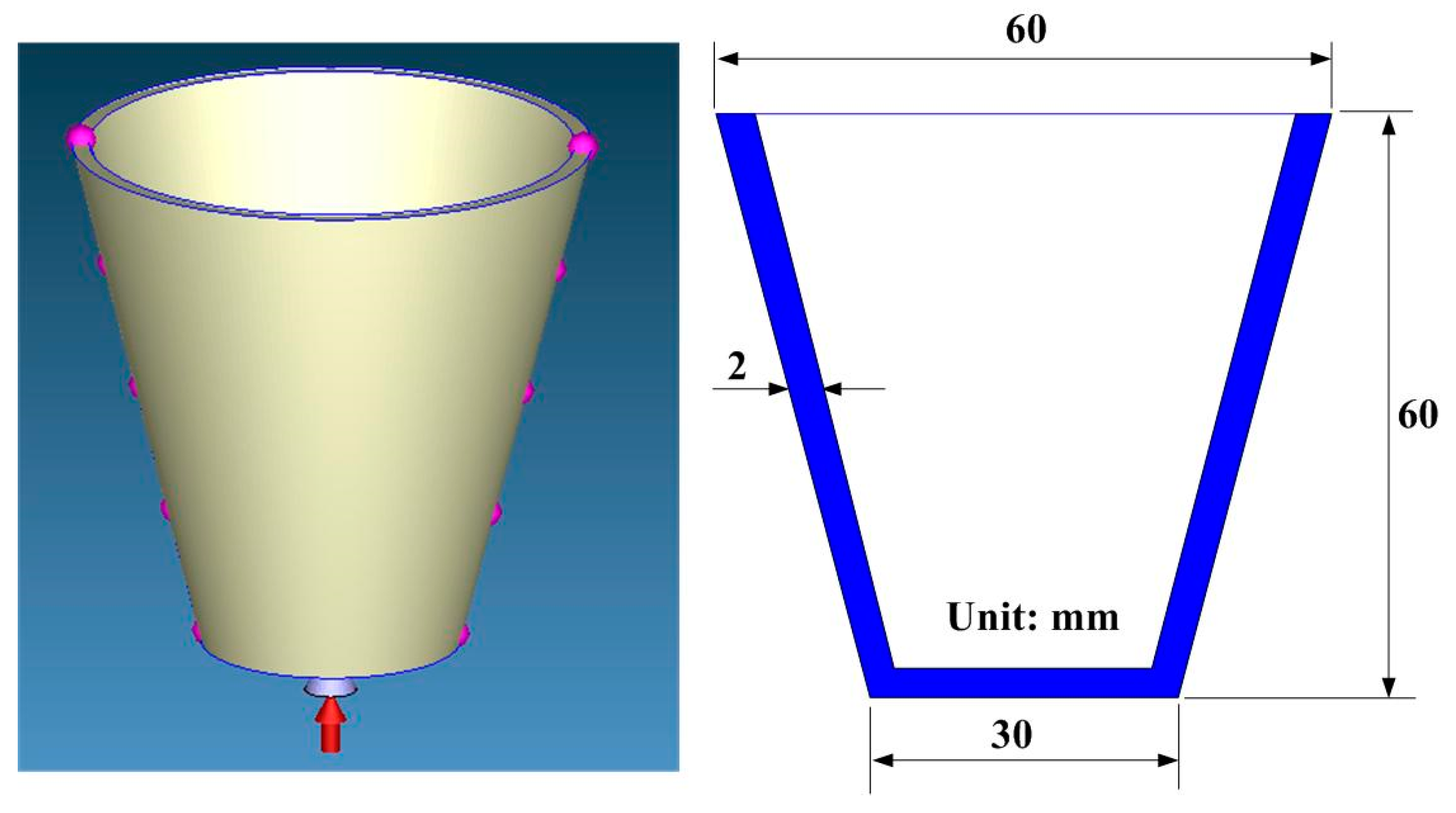
| Part thickness (mm) | 2 |
| Filling time (s) | 4.3 |
| Injection pressure (MPa) | 0.18 |
| Coolant flow rate (L/min) | 10 |
| Injection temperature (°C) | 82 |
| Mold temperature (°C) | 27 |
| Coolant temperature (°C) | 27 |
| Ejection temperature (°C) | 27 |
| Case Number | Cooling Time (s) | Part Temperature Difference (°C) | Mold Surface Temperature Difference (°C) | Total Displacement (mm) | Case Number | Cooling Time (s) | Part Temperature Difference (°C) | Mold Surface Temperature Difference (°C) | Total Displacement (mm) |
|---|---|---|---|---|---|---|---|---|---|
| 1 | 92.73 | 0.137 | 0.121 | 0.139 | 24 | 164.52 | 0.381 | 0.233 | 0.14 |
| 2 | 94.75 | 0.142 | 0.125 | 0.139 | 25 | 171.43 | 0.298 | 0.189 | 0.14 |
| 3 | 101.94 | 0.166 | 0.136 | 0.139 | 26 | 177.76 | 0.353 | 0.198 | 0.14 |
| 4 | 104.99 | 0.151 | 0.133 | 0.14 | 27 | 162.49 | 0.408 | 0.23 | 0.141 |
| 5 | 109.01 | 0.165 | 0.129 | 0.141 | 28 | 168.53 | 0.3 | 0.195 | 0.14 |
| 6 | 114.12 | 0.179 | 0.131 | 0.139 | 29 | 174.75 | 0.353 | 0.218 | 0.141 |
| 7 | 123.18 | 0.173 | 0.123 | 0.139 | 30 | 193.46 | 0.405 | 0.244 | 0.14 |
| 8 | 129.31 | 0.188 | 0.119 | 0.138 | 31 | 201.25 | 0.446 | 0.298 | 0.14 |
| 9 | 134.44 | 0.203 | 0.117 | 0.138 | 32 | 206.98 | 0.506 | 0.335 | 0.141 |
| 10 | 106.8 | 0.123 | 0.084 | 0.086 | 33 | 224.02 | 0.554 | 0.356 | 0.141 |
| 11 | 124.84 | 0.188 | 0.118 | 0.135 | 34 | 232.76 | 0.758 | 0.546 | 0.142 |
| 12 | 131.9 | 0.199 | 0.122 | 0.138 | 35 | 245.5 | 0.811 | 0.576 | 0.142 |
| 13 | 133.91 | 0.188 | 0.129 | 0.138 | 36 | 252.14 | 0.853 | 0.593 | 0.142 |
| 14 | 139.94 | 0.19 | 0.126 | 0.139 | 37 | 232.32 | 0.53 | 0.527 | 0.141 |
| 15 | 145.13 | 0.232 | 0.131 | 0.139 | 38 | 237.45 | 0.671 | 0.577 | 0.141 |
| 16 | 155.25 | 0.276 | 0.137 | 0.14 | 39 | 240.64 | 0.706 | 0.585 | 0.141 |
| 17 | 167.4 | 0.297 | 0.134 | 0.14 | 40 | 244.4 | 0.898 | 0.679 | 0.142 |
| 18 | 172.5 | 0.342 | 0.141 | 0.14 | 41 | 250.03 | 0.964 | 0.711 | 0.143 |
| 19 | 151.96 | 0.206 | 0.191 | 0.139 | 42 | 256.5 | 0.926 | 0.721 | 0.145 |
| 20 | 157.08 | 0.243 | 0.196 | 0.139 | 43 | 260.42 | 1.181 | 0.883 | 0.145 |
| 21 | 160.17 | 0.302 | 0.173 | 0.139 | 44 | 262.22 | 1.25 | 0.923 | 0.146 |
| 22 | 167.19 | 0.314 | 0.175 | 0.14 | 45 | 264.05 | 1.279 | 0.937 | 0.146 |
| 23 | 173.3 | 0.334 | 0.203 | 0.14 |
Publisher’s Note: MDPI stays neutral with regard to jurisdictional claims in published maps and institutional affiliations. |
© 2021 by the authors. Licensee MDPI, Basel, Switzerland. This article is an open access article distributed under the terms and conditions of the Creative Commons Attribution (CC BY) license (http://creativecommons.org/licenses/by/4.0/).
Share and Cite
Kuo, C.-C.; Nguyen, T.-D.; Zhu, Y.-J.; Lin, S.-X. Rapid Development of an Injection Mold with High Cooling Performance Using Molding Simulation and Rapid Tooling Technology. Micromachines 2021, 12, 311. https://doi.org/10.3390/mi12030311
Kuo C-C, Nguyen T-D, Zhu Y-J, Lin S-X. Rapid Development of an Injection Mold with High Cooling Performance Using Molding Simulation and Rapid Tooling Technology. Micromachines. 2021; 12(3):311. https://doi.org/10.3390/mi12030311
Chicago/Turabian StyleKuo, Chil-Chyuan, Trong-Duc Nguyen, Yi-Jun Zhu, and Shi-Xun Lin. 2021. "Rapid Development of an Injection Mold with High Cooling Performance Using Molding Simulation and Rapid Tooling Technology" Micromachines 12, no. 3: 311. https://doi.org/10.3390/mi12030311
APA StyleKuo, C.-C., Nguyen, T.-D., Zhu, Y.-J., & Lin, S.-X. (2021). Rapid Development of an Injection Mold with High Cooling Performance Using Molding Simulation and Rapid Tooling Technology. Micromachines, 12(3), 311. https://doi.org/10.3390/mi12030311