
Knowledge-Driven Manufacturing Process Innovation: A Case Study on Problem Solving in Micro-Turbine Machining

 ,
,  ,
,  ,
,
Abstract
:1. Introduction
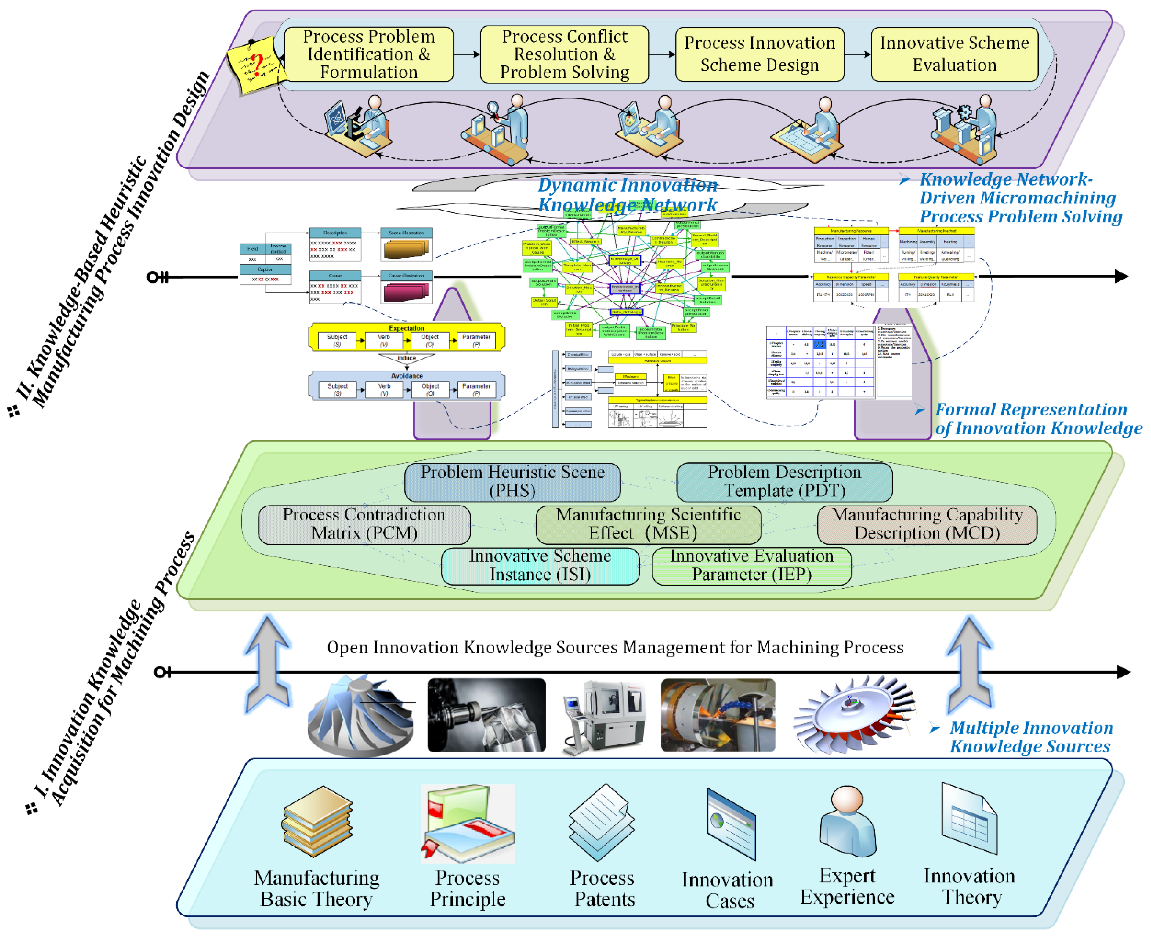
2. A Holistic Framework of Knowledge-Based Manufacturing Process Innovation Design
3. Innovation Knowledge Acquisition and Management for Machining Process
3.1. Sources and Contents of Machining Process Innovation Knowledge
- (1)
- Basic manufacturing theories. Basic manufacturing theories refer to the general laws of natural science that can provide guidance for applied research. They are the basic scientific principles that manufacturing process innovation activities should follow, such as the theories and principles of physics, chemistry, geometry, materials, and biology.
- (2)
- Technical process principles. Technical process principles relate to the manufacturing methods and mechanisms that guide the production of parts and entire products in the manufacturing environment, such as cutting and measuring.
- (3)
- Process patents and innovation cases. Process patents are an important knowledge source for manufacturing innovation that reflect the latest advances in multi-disciplinary fields involved in new technologies, new processes, new methods, etc. Innovation cases can reflect the manufacturing ability and characteristics of an organization and can be used as a powerful reference for solving similar process problems and innovative scheme design.
- (4)
- Expert experience. Expert experience refers to machining know-how, and experience and methods in the field of manufacturing that exist in the minds of manufacturing professionals and operators. Expert experience is a valuable asset accumulated through project experience, so explicit expert experience can be regarded as an important innovation knowledge source for the machining process.
- (5)
3.2. Open Multi-Source Knowledge Acquisition for Machining Process Innovation
4. Knowledge-Driven Problem-Solving and Innovation Design Method for Micromachining Process
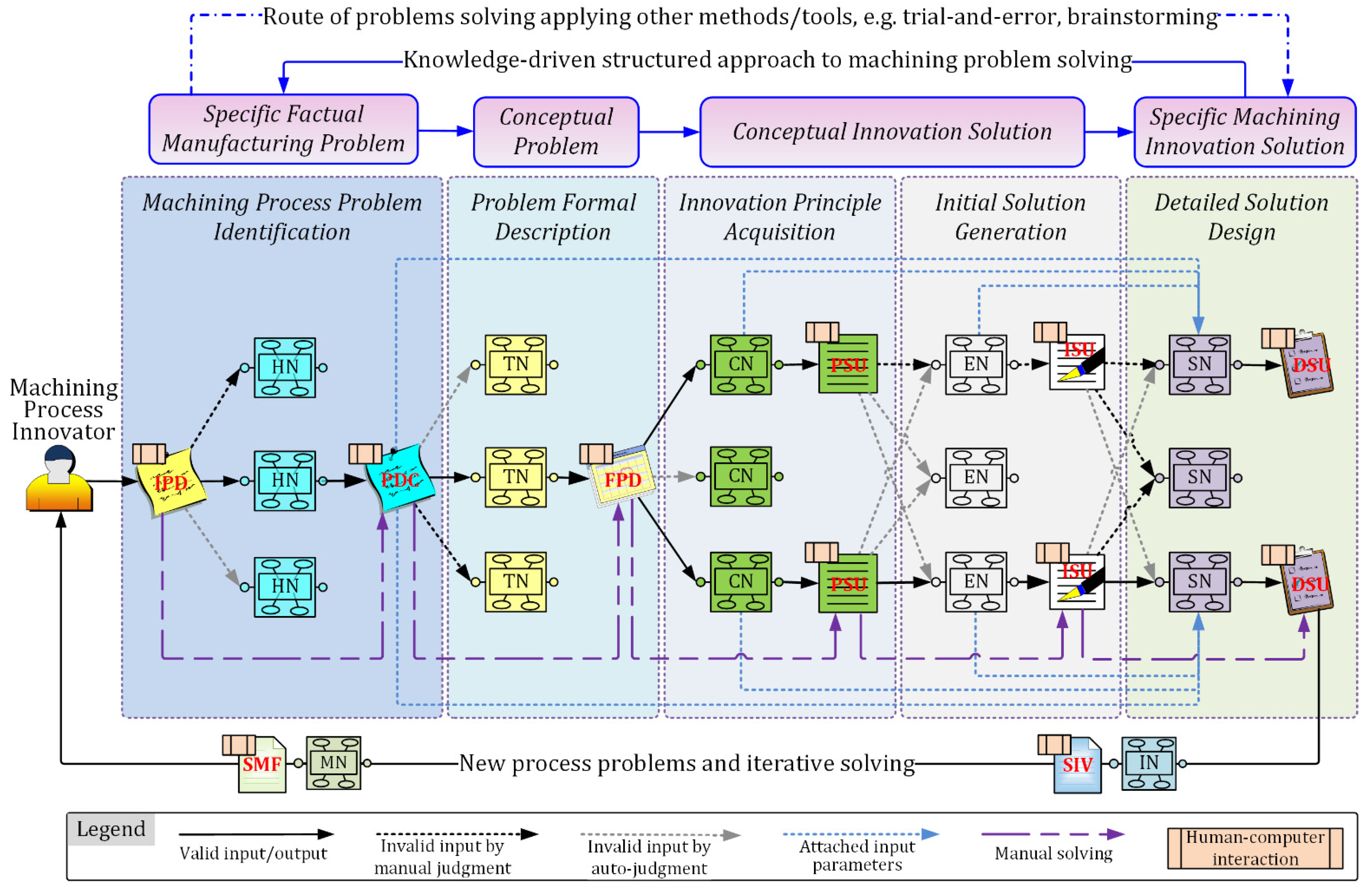
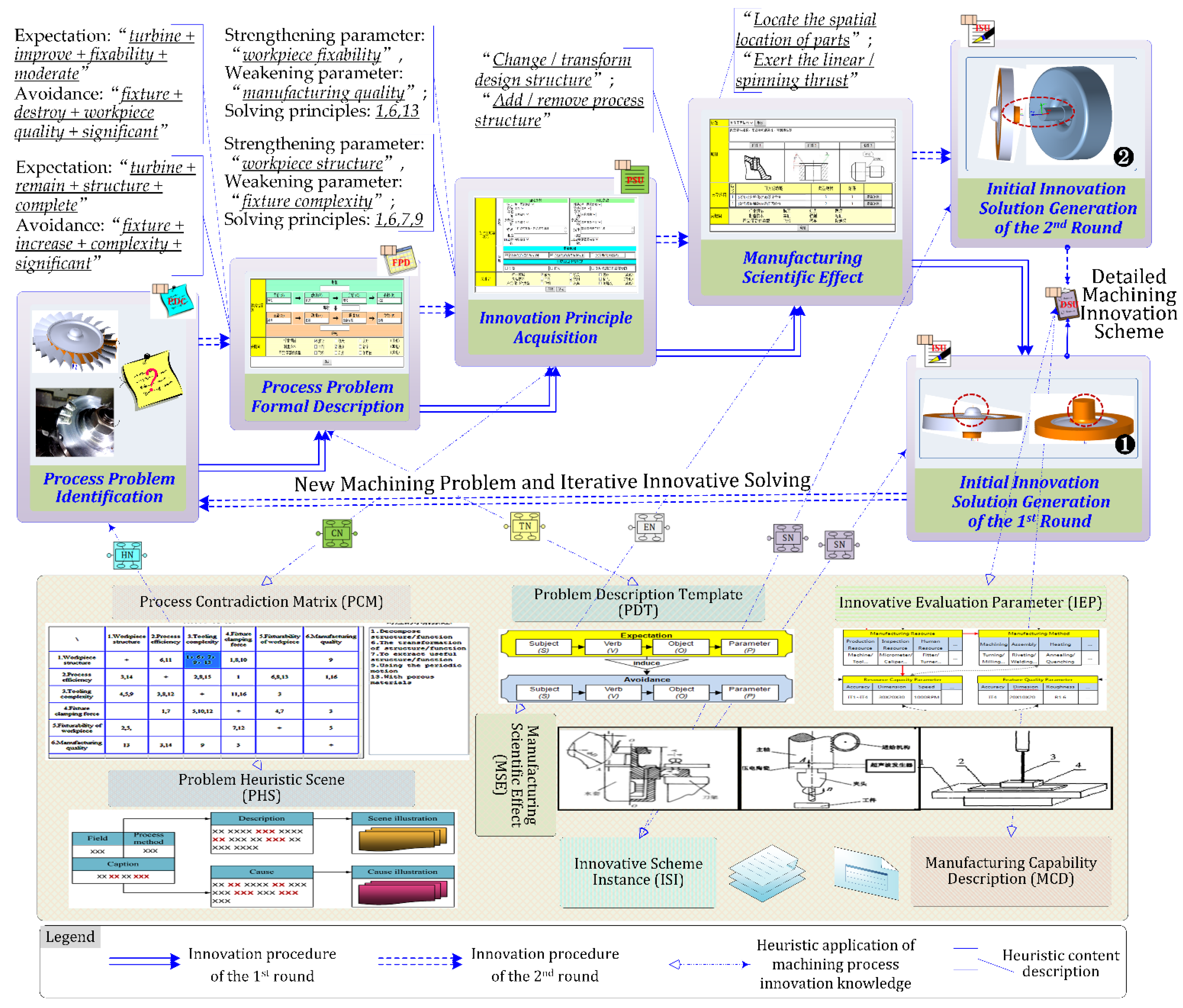
4.1. Structured Problem-Solving and Innovation Design Procedure of Machining Process
- (1)
- Process problem identification. The machining process innovator manually inputs the IPD according to the identified machining problem. Then, the HNs that meet the threshold of semantic similarity with the description of IPD are automatically listed for heuristic innovation. The innovator can then interactively input the cause of the process problem and generate the PDC, based on the selected HNs. Finally, the selected HNs transfer the PDC to all TNs.
- (2)
- Problem formal description. After the TNs accept the PDC, they will determine if they can be applied to the PDC according to the problem domain. Then, the innovator can retrieve the objective and obstacles of the problem, based on the PDC and recommended TNs, and interactively input them to form the FPD, which will be transferred to all CNs. Finally, the FPD formation process is constrained and standardized using the domain ontology database.
- (3)
- Innovation principle acquisition. Each CN represents a unit of the machining contradiction matrix. After accepting the FPD, the CNs automatically parse the contradiction parameters in the FPD. If the parsed contradiction parameters are matched with the CNs, the solving principles in the CNs will be extracted as PSU under human–computer interaction and output as the function requirement format to all ENs.
- (4)
- Initial solution generation. Each EN is a triple combination of effect, function, and typical structure. After accepting the PSU, each EN will automatically build a comparison between the function requirement of PSU and its realizable function. If they are matched, the corresponding effect and typical structure will be output as ISU to the SNs.
- (5)
- Detailed solution design. When the SN has accepted the ISU, it calculates the similarity between itself and the ISU, referencing the previous TN, CN, and EN. Then, the system automatically lists the SNs that meet the threshold of similarity for the machining process innovator to refer to. The innovator can then reuse the SNs or interactively input information to generate the DSU inspired by the SNs.
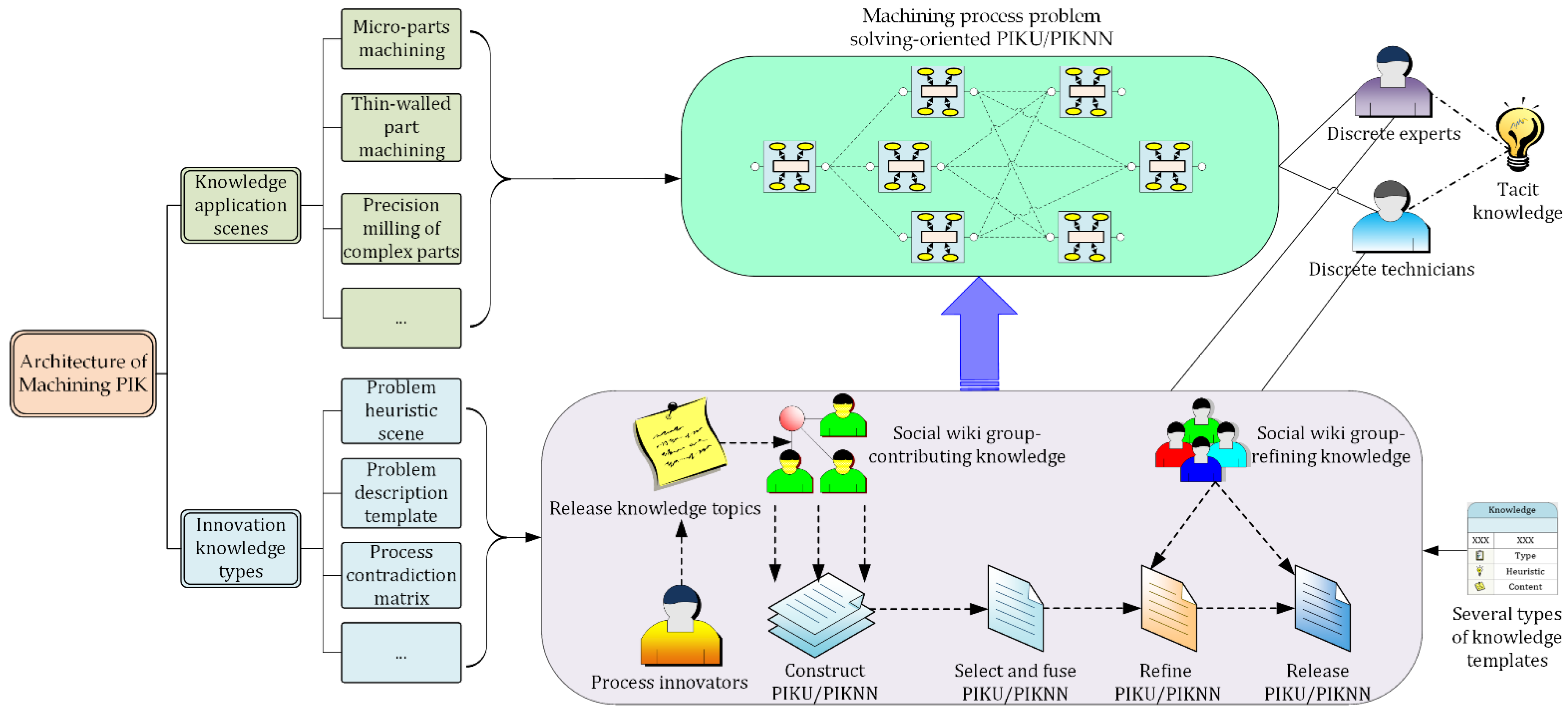
4.2. Heuristic Innovation Knowledge Processing Architecture of Problem Solving
5. Knowledge-Driven Process Problem Solving for Micro-Turbine Machining
5.1. Process Problems Description of Micro-Turbine Machining
- (1)
- The blade is a thin-walled part with poor process rigidity, more serious deformation, and higher processing accuracy requirements.
- (2)
- As the size of the turbine is reduced, the diameter of the tool is also reduced, and so the rigidity of the tool becomes worse and is easier to break.
- (3)
- The flow path between the blades is narrower and deeper, and the processing space is smaller. The relative swing of the tool during processing can easily cause cutting interference to the adjacent blades.
- (4)
- The turbine center has no through-hole structure, which brings difficulties in turbine clamping.
- (5)
- The thickness of the blade is variable. The thickness at the root of the blade is 1.1 mm, and the thickness at the tip of the blade is only 0.8 mm. The blade is thin and easily deformed. It is required to be free of burrs after machining.
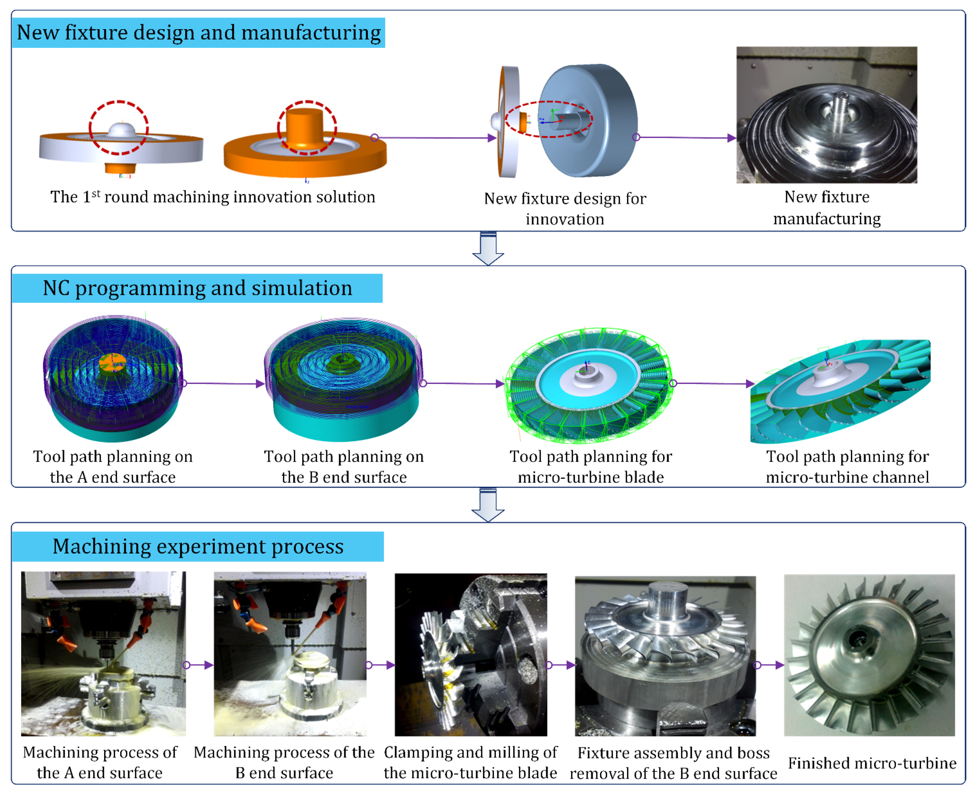
5.2. Knowledge-Inspired Process Innovation Scheme Design and Machining Experiment
6. Conclusions
- By analyzing the knowledge requirements of computer-aided machining process innovation, several types of MPIK units and the corresponding knowledge network are formally represented. An open multi-source MPIK acquisition and management approach based on collective intelligence is introduced.
- In considering the specific role of formal knowledge in human–computer interaction innovation, a knowledge network-driven structured problem-solving and heuristic innovation design procedure for the machining process is presented that can support process planners in reducing inherent mindsets and individual knowledge limitations and facilitate knowledge-based heuristic innovation.
- The specific micromachining process problem-solving and innovation design for a micro-turbine, without a through-hole, is completed using the innovation support prototype system, MPI-KHDS. The machining experiment shows that the machining quality of the micro-turbine, with the innovation scheme, is significantly improved.
Author Contributions
Funding
Acknowledgments
Conflicts of Interest
References
- Moslemipour, G.; Lee, T.; Rilling, D. A review of intelligent approaches for designing dynamic and robust layouts in flexible manufacturing systems. Int. J. Adv. Manuf. Technol. 2012, 60, 11–27. [Google Scholar] [CrossRef]
- Li, B.H.; Hou, B.C.; Yu, W.T.; Lu, X.B.; Yang, C.W. Applications of artificial intelligence in intelligent manufacturing: A review. Front. Inf. Technol. Electron. Eng. 2017, 18, 86–96. [Google Scholar] [CrossRef]
- Zhang, Q.; Lu, J.; Jin, Y. Artificial intelligence in recommender systems. Complex Intell. Syst. 2021, 7, 439–457. [Google Scholar] [CrossRef]
- Feng, Y.X.; Zhao, Y.L.; Zheng, H.; Li, Z.W.; Tan, J.R. Data-driven product design toward intelligent manufacturing: A review. Int. J. Adv. Rob. Syst. 2020, 17, 1729881420911257. [Google Scholar] [CrossRef]
- Wu, L.; Leng, J.; Ju, B. Digital twins-based smart design and control of ultra-precision machining: A review. Symmetry 2021, 13, 1717. [Google Scholar] [CrossRef]
- Lee, Y.J.; Wang, H. Current understanding of surface effects in microcutting. Mater. Des. 2020, 192, 108688. [Google Scholar] [CrossRef]
- Luo, X.; Cheng, K.; Webb, D.; Wardle, F. Design of ultraprecision machine tools with applications to manufacture of miniature and micro components. J. Mater. Process. Technol. 2005, 167, 515–528. [Google Scholar] [CrossRef] [Green Version]
- Friedrich, C.R.; Coane, P.J.; Vasile, M.J. Micromilling development and applications for microfabrication. Microelectron. Eng. 1997, 35, 367–372. [Google Scholar] [CrossRef]
- Takacs, M.; Vero, B.; Meszaros, I. Micromilling of metallic materials. J. Mater. Process. Technol. 2003, 138, 152–155. [Google Scholar] [CrossRef]
- Wang, B.; Zhang, P.; Liang, Y.C.; Dong, S. Development of the control system for three-axis ultraprecision compact micromilling machine. J. Vac. Sci. Technol. B 2009, 27, 1285–1287. [Google Scholar] [CrossRef]
- Cardoso, P.; Davim, J.P. Optimization of surface roughness in micromilling. Mater. Manuf. Process. 2010, 25, 1115–1119. [Google Scholar] [CrossRef]
- Son, S.M.; Lim, H.S.; Ahn, J.H. Effects of the friction coefficient on the minimum cutting thickness in micro cutting. Int. J. Mach. Tools Manuf. 2005, 45, 529–535. [Google Scholar] [CrossRef]
- Ba, S.; Jain, N.; Joseph, V.R.; Singh, R. Integrating analytical models with finite-element models: An application in micromachining. J. Qual. Technol. 2013, 45, 200–212. [Google Scholar] [CrossRef]
- Balazs, B.Z.; Jacso, A.; Takacs, M. Micromachining of hardened hot-work tool steel: Effects of milling strategies. Int. J. Adv. Manuf. Technol. 2020, 108, 2839–2854. [Google Scholar] [CrossRef]
- Ayhan, M.B.; Öztemel, E.; Aydin, M.E.; Yue, Y. A quantitative approach for measuring process innovation: A case study in a manufacturing company. Int. J. Prod. Res. 2013, 51, 3463–3475. [Google Scholar] [CrossRef]
- Yamamoto, Y.; Bellgran, M. Four types of manufacturing process innovation and their managerial concerns. Proc. CIRP 2013, 7, 479–484. [Google Scholar] [CrossRef] [Green Version]
- Bonnardel, N.; Didier, J. Brainstorming variants to favor creative design. Appl. Ergon. 2020, 83, 102987. [Google Scholar] [CrossRef] [PubMed]
- Leon, N. The future of computer-aided innovation. Comput. Ind. 2009, 60, 539–550. [Google Scholar] [CrossRef]
- Cugini, U.; Cascini, G.; Muzzupappa, M.; Nigrelli, V. Integrated computer-aided innovation: The prosit approach. Comput. Ind. 2009, 60, 629–641. [Google Scholar] [CrossRef]
- Xu, J.; Houssin, R.; Caillaud, E.; Gardoni, M. Fostering continuous innovation in design with an integrated knowledge management approach. Comput. Ind. 2011, 62, 423–436. [Google Scholar] [CrossRef] [Green Version]
- Esterhuizen, D.; Schutte, C.S.L.; du Toit, A.S.A. Knowledge creation processes as critical enablers for innovation. Int. J. Inf. Manag. 2012, 32, 354–364. [Google Scholar] [CrossRef]
- Duran-Novoa, R.; Leon-Rovira, N.; Aguayo-Tellez, H.; Said, D. Inventive problem solving based on dialectical negation, using evolutionary algorithms and triz heuristics. Comput. Ind. 2011, 62, 437–445. [Google Scholar] [CrossRef]
- Fiorineschi, L.; Frillici, F.S.; Rotini, F.; Conti, L.; Rossi, G. Adapted use of the triz system operator. Appl. Sci. 2021, 11, 6476. [Google Scholar] [CrossRef]
- Cakir, M.C.; Cilsal, O.O. Implementation of a contradiction-based approach to dfm. Int. J. Comput. Integr. Manuf. 2008, 21, 839–847. [Google Scholar] [CrossRef]
- Delgado-Maciel, J.; Cortes-Robles, G.; Sanchez-Ramirez, C.; Garcia-Alcaraz, J.; Mendez-Contreras, J.M. The evaluation of conceptual design through dynamic simulation: A proposal based on triz and system dynamics. Comput. Ind. Eng. 2020, 149, 106785. [Google Scholar] [CrossRef]
- Hüsig, S.; Kohn, S. “Open cai 2.0”—Computer aided innovation in the era of open innovation and web 2.0. Comput. Ind. 2011, 62, 407–413. [Google Scholar] [CrossRef]
- Lopez Flores, R.; Belaud, J.-P.; Le Lann, J.-M.; Negny, S. Using the collective intelligence for inventive problem solving: A contribution for open computer aided innovation. Expert. Syst. Appl. 2015, 42, 9340–9352. [Google Scholar] [CrossRef] [Green Version]
- Yusof, Y.; Latif, K. Survey on computer-aided process planning. Int. J. Adv. Manuf. Technol. 2014, 75, 77–89. [Google Scholar] [CrossRef] [Green Version]
- El Kadiri, S.; Kiritsis, D. Ontologies in the context of product lifecycle management: State of the art literature review. Int. J. Prod. Res. 2015, 53, 5657–5668. [Google Scholar] [CrossRef]
- García-Alcaraz, J.L.; Alvarado I, A. Problems in the implementation process of advanced manufacturing technologies. Int. J. Adv. Manuf. Technol. 2013, 64, 123–131. [Google Scholar] [CrossRef]
- Al-wswasi, M.; Ivanov, A.; Makatsoris, H. A survey on smart automated computer-aided process planning (acapp) techniques. Int. J. Adv. Manuf. Technol. 2018, 97, 809–832. [Google Scholar] [CrossRef] [Green Version]
- Wang, G.; Tian, X.; Geng, J.; Guo, B. A knowledge accumulation approach based on bilayer social wiki network for computer-aided process innovation. Int. J. Prod. Res. 2015, 53, 2365–2382. [Google Scholar] [CrossRef]
- Duflou, J.R.; D’hondt, J. Applying triz for systematic manufacturing process innovation: The single point incremental forming case. Proc. Eng. 2011, 9, 528–537. [Google Scholar] [CrossRef] [Green Version]
- Cavallucci, D.; Leon, N. Computer-supported innovation pipelines: Current research and trends. Comput. Ind. 2011, 62, 375–376. [Google Scholar] [CrossRef]
- Wang, G.; Tian, X.; Geng, J.; Evans, R.; Che, S. Extraction of principle knowledge from process patents for manufacturing process innovation. Proc. CIRP 2016, 56, 193–198. [Google Scholar] [CrossRef] [Green Version]
- Gao, J.; Nee, A.Y. An overview of manufacturing knowledge sharing in the product development process. Proc. IMechE Part B J. Eng. Manuf. 2018, 232, 2253–2263. [Google Scholar] [CrossRef]
- Beydoun, G.; Hoffmann, A.; Garcia, R.V.; Shen, J.; Gill, A. Towards an assessment framework of reuse: A knowledge-level analysis approach. Complex Intell. Syst. 2020, 6, 87–95. [Google Scholar] [CrossRef] [Green Version]
- Cavallucci, D.; Khomenko, N. From triz to otsm-triz: Addressing complexity challenges in inventive design. Int. J. Prod. Dev. 2007, 4, 4–21. [Google Scholar] [CrossRef]
- Yan, W.; Liu, H.; Zanni-Merk, C.; Cavallucci, D. Ingenioustriz: An automatic ontology-based system for solving inventive problems. Knowl.-Based Syst. 2015, 75, 52–65. [Google Scholar] [CrossRef]
- Chechurin, L.; Borgianni, Y. Understanding triz through the review of top cited publications. Comput. Ind. 2016, 82, 119–134. [Google Scholar] [CrossRef]
- Oentaryo, R.J.; Pasquier, M. Knowledge consolidation and inference in the integrated neuro-cognitive architecture. IEEE Intell. Syst. 2011, 26, 62–71. [Google Scholar] [CrossRef]


| Type | Concept | Function |
|---|---|---|
| Problem Heuristic Scene (PHS) | Abstract and formalized phenomenon description of typical process problems to facilitate the cause analysis of problem scenes | To stimulate technicians to associate their tacit knowledge in order to recognize and analyze problems effectively and correctly |
| Problem Description Template (PDT) | Formalized representation framework according to the essential structure of machining process problem | Providing constraints for the formal description of process problems to ensure the clarity of problem expression and the understandability |
| Process Contradiction Matrix (PCM) | The relationships between technical parameters, contradictions, and process innovation principles | Providing the solving direction and principal solution for the structural conflict resolution of process problems |
| Manufacturing Scientific Effect (MSE) | Manufacturing-oriented and multidisciplinary basic scientific effects | Providing the basic technical framework and scientific effects for preliminary innovative solution design |
| Innovative Scheme Instance (ISI) | Formalized, practical, and successful schemes for typical process problems | Providing technical implementation reference solutions to support the detailed innovative scheme design |
| Innovative Evaluation Parameter (IEP) | Evolution path parameters and lifecycle phase parameters of all technical systems | Providing the quantitative evaluation parameters to identify the innovativeness grade of innovative solution |
| Manufacturing Capability Description (MCD) | Formalized description of manufacturing capability for the specific enterprise | Evaluating the manufacturing feasibility of the innovative scheme in the firm-specific manufacturing environment |
| Type | Ontology Contents |
|---|---|
| Process Data Ontology | Initial Problem Description (IPD) |
| Problem Description with Cause (PDC) | |
| Formalized Problem Description (FPD) | |
| Principle Solution (PSU) | |
| Initial Solution (ISU) | |
| Detailed Solution (DSU) | |
| Solution Innovativeness (SIV) | |
| Solution Manufacturability (SMF) | |
| Knowledge Ontology | Heuristic Neuron (HN) |
| Template Neuron (TN) | |
| Contradiction Neuron (CN) | |
| Effect Neuron (EN) | |
| Solution Neuron (SN) | |
| Innovativeness Neuron (IN) | |
| Manufacturability Neuron (MN) |
| Rule | Description |
|---|---|
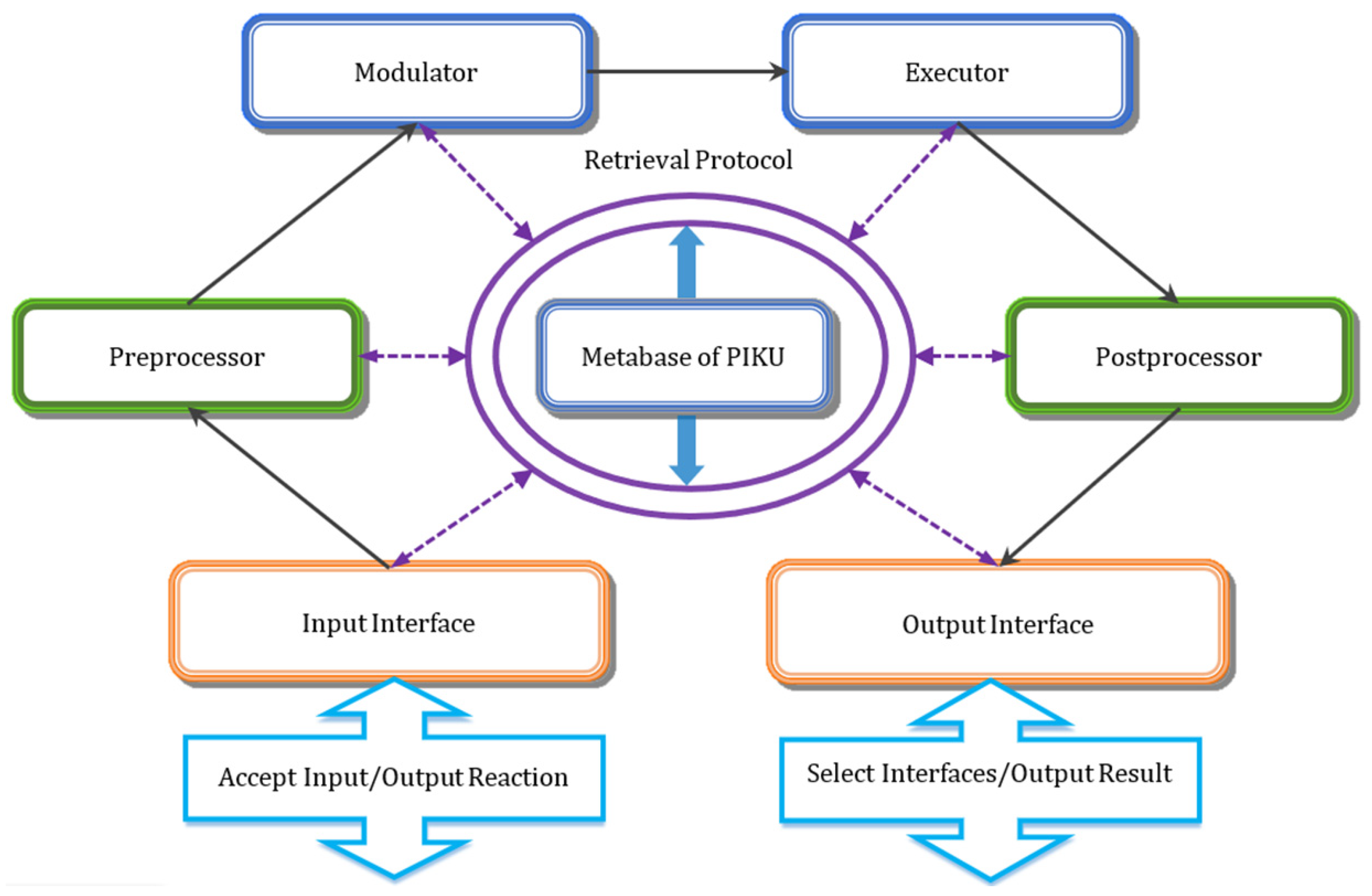
| Interface Matching | Considering that the semantic relations and processing rules among various types of machining PIKUs are explicit, the forward propagation mode is adopted to transfer the parameters without feedback learning. Through the output interface, the current PIKU will select all subsequent PIKUs that can accept their output parameter types and transfer the output results to the input interface of subsequent PIKUs. |
| Parameter Judgment | There are two methods for judging the effectiveness of input parameters. The first is to determine automatically whether the parameter is effective, according to the processing rules, and the second is to manually intervene. In both ways, as long as the parameters are ineffective, the current machining PIKU will interrupt its knowledge transfer process. |
| Knowledge Processing | There are two ways to process the input parameters. One way is to automatically process by PIKUs, based on the knowledge properties and processing rules, while the other way requires manual intervention and to output the processing results. |
| Manual Solving | If there are no suitable machining PIKUs to use at a solving step of process innovation, then the solution process will be transferred to manual solving. Subsequently, the result of manual solving will be transferred to the next-level PIKUs to continue the solving process. |
Publisher’s Note: MDPI stays neutral with regard to jurisdictional claims in published maps and institutional affiliations. |
© 2021 by the authors. Licensee MDPI, Basel, Switzerland. This article is an open access article distributed under the terms and conditions of the Creative Commons Attribution (CC BY) license (https://creativecommons.org/licenses/by/4.0/).
Share and Cite
Zhang, D.; Wang, G.; Xin, Y.; Shi, X.; Evans, R.; Guo, B.; Huang, P. Knowledge-Driven Manufacturing Process Innovation: A Case Study on Problem Solving in Micro-Turbine Machining. Micromachines 2021, 12, 1357. https://doi.org/10.3390/mi12111357
Zhang D, Wang G, Xin Y, Shi X, Evans R, Guo B, Huang P. Knowledge-Driven Manufacturing Process Innovation: A Case Study on Problem Solving in Micro-Turbine Machining. Micromachines. 2021; 12(11):1357. https://doi.org/10.3390/mi12111357
Chicago/Turabian StyleZhang, Dong, Gangfeng Wang, Yupeng Xin, Xiaolin Shi, Richard Evans, Biao Guo, and Pu Huang. 2021. "Knowledge-Driven Manufacturing Process Innovation: A Case Study on Problem Solving in Micro-Turbine Machining" Micromachines 12, no. 11: 1357. https://doi.org/10.3390/mi12111357
APA StyleZhang, D., Wang, G., Xin, Y., Shi, X., Evans, R., Guo, B., & Huang, P. (2021). Knowledge-Driven Manufacturing Process Innovation: A Case Study on Problem Solving in Micro-Turbine Machining. Micromachines, 12(11), 1357. https://doi.org/10.3390/mi12111357