Magnetostrictive Performance of Electrodeposited TbxDy(1−x)Fey Thin Film with Microcantilever Structures

 ,
,  and
and
Abstract
1. Introduction
2. Experimental
3. Result and Discussion
4. Conclusion
Author Contributions
Funding
Acknowledgments
Conflicts of Interest
References
- Engdahl, G.; Mayergoyz, I.D. Handbook of Giant Magnetostrictive Materials; Academic Press: Cambridge, MA, USA, 2000. [Google Scholar]
- Clark, A.E. Handbook of Ferromagnetic Material; North-Holland Publishing Company: Amsterdam, The Netherlands, 1980; Volume 1, pp. 531–583. [Google Scholar]
- Buschow, K.H.J.; Wohlfarth, E.P. Handbook of Ferromagnetic Material; Elsevier Science Publishers B.V: Amsterdam, The Netherlands, 1990; Volume 5, pp. 1–132. [Google Scholar]
- Mnyukh, Y. The True Cause of Magnetostriction. Am. J. Condens. Matter Phys. 2014, 4, 57–62. [Google Scholar]
- McGary, P.D.; Reddy, K.S.; Haugstad, G.D.; Stadler, B.J. Combinatorial Electrodeposition of Magnetostrictive Fe1−xGax. J. Electrochem. Soc. 2010, 157, D656–D665. [Google Scholar] [CrossRef]
- Ng, J.H.G.; Record, P.M.; Shang, X.; Wlodarczyk, K.L.; Hand, D.P.; Schiavone, G.; Abraham, E.; Cummins, G.; Desmulliez, M.P. Optimised co-electrodeposition of Fe–Ga alloys for maximum magnetostriction effect. Sens. Actuators A 2015, 223, 91–96. [Google Scholar] [CrossRef]
- Houqing, Z.; Jianguo, L.; Xiurong, W.; Yanhong, X.; Hongping, Z. Applications of Terfenol-D in China. J. Alloys Compd. 1997, 258, 49–52. [Google Scholar] [CrossRef]
- Thang, P.D.; Rijnders, G.; Blank, D.H.A. Stress-induced magnetic anisotropy of CoFe2O4 thin films using pulsed laser deposition. J. Magn. Magn. Mater. 2007, 3, 2621–2623. [Google Scholar] [CrossRef]
- Özkale, B.; Shamsudhin, N.; Bugmann, T.; Nelson, B.J.; Pané, S. Magnetostriction in electroplated CoFe alloys. Electrochem. Commun. 2017, 76, 15–19. [Google Scholar] [CrossRef]
- Yamaura, S.I.; Nakajima, T.; Satoh, T.; Ebata, T.; Furuya, Y. Magnetostriction of heavily deformed Fe–Co binary alloys prepared by forging and cold rolling. Mater. Sci. Eng. B 2015, 193, 121–129. [Google Scholar] [CrossRef]
- Hunter, D.; Osborn, W.; Wang, K.; Kazantseva, N.; Hattrick-Simpers, J.; Suchoski, R.; Takahashi, R.; Young, M.L.; Mehta, A.; Bendersky, L.A.; et al. Giant magnetostriction in annealed Co1–xFex thin-films. Nat. Commun. 2011, 2, 518. [Google Scholar] [CrossRef]
- Yamazaki, T.; Yamamoto, T.; Furuya, Y.; Nakao, W. Magnetic and magnetostrictive properties in heat-treated Fe-Co wire for smart material/ device. Jpn. Soc. Mech. Eng. 2018, 5, 17–00569. [Google Scholar] [CrossRef]
- Tiercelin, N.; Youssef, J.B.; Preobrazhensky, V.; Pernod, P.; Le Gall, H. Giant magnetostrictive superlattices: From spin reorientation transition to MEMS. Static and dynamical properties. J. Magn. Magn. Mater. 2002, 249, 519–523. [Google Scholar] [CrossRef]
- Lim, S.H.; Han, S.H.; Kim, H.J.; Choi, Y.S.; Choi, J.W.; Ahn, C.H. Prototype microactuators driven by magnetostrictive thin films. IEEE Trans. Magn. 1998, 34, 2042–2044. [Google Scholar] [CrossRef]
- Fu, L.; Li, S.; Zhang, K.; Chen, I.; Petrenko, V.; Cheng, Z. Magnetostrictive Microcantilever as an Advanced Transducer for Biosensors. Sensors 2007, 7, 2929–2941. [Google Scholar] [CrossRef] [PubMed]
- Fu, L.; Li, S.; Zhang, K.; Chen, I.H.; Barbaree, J.M.; Zhang, A.; Cheng, Z. Detection of Bacillus anthracis Spores Using Phage-Immobilized Magnetostrictive Milli/Micro Cantilevers. IEEE Sens. J. 2011, 11, 1684–1691. [Google Scholar] [CrossRef]
- Wang, L.; Yuan, F.G. Vibration energy harvesting by magnetostrictive material. Smart Mater. Struct. 2008, 17, 045009. [Google Scholar] [CrossRef]
- Kawashima, K.; Mineta, T.; Makino, E.; Kawashima, T.; Shibata, T. Self-Align Fabrication of Narrow-Gapped Dual AFM Tip Using Si Trench Refilling with SOG and Magnetostrictive Film Stacked Dual Cantilever Formation. Electron. Commun. Jpn. 2015, 98, 90–95. [Google Scholar] [CrossRef]
- Panduranga, M.K.; Lee, T.; Chavez, A.; Prikhodko, S.V.; Carman, G.P. Polycrystalline Terfenol-D thin films grown at CMOS compatible temperature. AIP Adv. 2018, 8, 056404-1-5. [Google Scholar] [CrossRef]
- Mohanchandra, K.P.; Prikhodko, S.V.; Wetzlar, K.P.; Sun, W.Y.; Nordeen, P.; Carman, G.P. Sputter deposited Terfenol-D thin films for multiferroic applications. AIP Adv. 2015, 5, 097119-1-9. [Google Scholar] [CrossRef]
- Kerrigan, C.A.; Ho, K.K.; Mohanchandra, K.P.; Carman, G.P. Sputter deposition and analysis of thin film Nitinol/Terfenol-D multilaminate for vibration damping. Smart Mater. Struct. 2009, 18, 015007. [Google Scholar] [CrossRef]
- Loveless, M.; Guruswamy, S. Texture in magnetic annealed Terfenol-D films. J. Appl. Phys. 1996, 79, 6222–6224. [Google Scholar] [CrossRef]
- Schatz, F.; Hirscher, M.; Schnell, M.; Flik, G.; Kronmiiller, H. Magnetic anisotropy and giant magnetostriction of amorphous TbDyFe films. J. Appl. Phys. 1994, 76, 5380–5382. [Google Scholar] [CrossRef]
- Quandt, E. Multitarget sputtering of high magnetostrictive Tb-Dy-Fe films. J. Appl. Phys. 1994, 75, 5653–5655. [Google Scholar] [CrossRef]
- Liu, M.; Li, S.; Zhou, Z.; Beguhn, S.; Lou, J.; Xu, F.; Jian Lu, T.; Sun, N.X. Electrically induced enormous magnetic anisotropy in Terfenol-D/lead zinc niobatelead titanate multiferroic heterostructures. J. Appl. Phys. 2012, 112, 063917-1-4. [Google Scholar] [CrossRef]
- Loveless, M.; Guruswamy, S.; Shield, J.E. Crystallization Behavior of Amorphous Terfenol-D Thin Films. IEEE Trans. Magn. 2012, 33, 3937–3939. [Google Scholar] [CrossRef]
- Jerzy, K.; Rafal, M.; Mariusz, H. Magnetomechanical properties of Terfenol-D based composites. In Proceedings of the 6th International Conference on Mechanics and Materials in Design Ponta Delgada/Azores, Ponta Delgada, Portugal, 26–30 July 2015; pp. 683–690. [Google Scholar]
- Meníc, J.; Quandt, E.; Munz, D. Elastic modulus of TbDyFe films a comparison of nanoindentation and bending measurements. Thin Solid Films 1996, 287, 208–213. [Google Scholar]
- Gong, J.; Podlaha, E.J. Electrodeposition of Fe-Tb Alloys from an Aqueous Electrolyte. Electrochem. Solid State Lett. 2000, 3, 422–425. [Google Scholar] [CrossRef]
- Zarkadas, G.M.; Stergiou, A.; Papanastasiou, G. Influence of citric acid on the silver electrodeposition from aqueous AgNO3 solutions. Electrochim. Acta 2005, 50, 5022–5031. [Google Scholar] [CrossRef]
- Aaboubi, O.; Douglade, J.; Abenaqui, X.; Boumedmed, R.; VonHoff, J. Influence of tartaric acid on zinc electrodeposition from sulphate bath. Electrochim. Acta 2011, 56, 7885–7889. [Google Scholar] [CrossRef]
- Fashu, S.; Gu, C.D.; Zhang, J.L.; Huang, M.L.; Wang, X.L.; Tu, J.P. Effect of EDTA and NH4Cl additives on electrodeposition of Zn−Ni films from choline chloride-based ionic. Trans. Nonferrous Met. Soc. China 2015, 25, 2054–2064. [Google Scholar] [CrossRef]
- Wang, T.; Chen, Y.N.; Chiang, C.C.; Hsieh, Y.K.; Li, P.C.; Wang, C.F. Carbon-Coated Hematite Electrodes with Enhanced Photoelectrochemical Performance Obtained through an Electrodeposition Method with a Citric Acid Additive. ChemElectroChem 2016, 3, 966–975. [Google Scholar] [CrossRef]
- Shim, H.; Sakamoto, K.; Inomata, N.; Toda, M.; Van Toan, N.; Song, Y.; Ono, T. Magnetostrictive performance of electrodeposited TbxDy1-xFey thin film evaluated from microactuator. In Proceedings of the 2019 20th International Conference on Solid-State Sensors, Actuators and Microsystems & Eurosensors XXXIII (TRANSDUCERS & EUROSENSORS XXXIII), Berlin, Germany, 23–27 June 2019; pp. 1698–1700. [Google Scholar]
- Yang, Y.V.; Huang, Y.Y.; Jin, Y.M. Effects of magnetocrystalline anisotropy constant K2 on magnetization and magnetostriction of Terfenol-D. Appl. Phys. Lett. 2011, 9, 012503. [Google Scholar] [CrossRef]
- Klokholm, E. The measurement of magnetostriction in ferromagnetic thin films. IEEE Trans. Magn. 1976, 12, 819–821. [Google Scholar] [CrossRef]
- De Lacheisserie, E.D.T.; Peuzin, J.C. Magnetostriction and internal stresses in thin films: The cantilever method revisited. J. Magn. Magn. Mater. 1994, 136, 189–196. [Google Scholar] [CrossRef]
- Budynas, R.G.; Young, W.C.; Sadegh, A. Roark’s Formulas for Stress and Strain, 8th ed.; Mc Garw Hill: New York, NY, USA, 2012; pp. 165–169. [Google Scholar]
- Antunes, J.M.; Fernandes, J.V.; Sakharova, N.A.; Oliveira, M.C.; Menezes, L.F. On the determination of the Young’s modulus of thin films using indentation tests. Int. J. Solids Struct. 2007, 44, 8313–8334. [Google Scholar] [CrossRef]
- Krulevitch, P.; Lee, A.P.; Ramsey, P.B.; Trevino, J.C.; Hamilton, J.; Northrup, M.A. Thin film shape memory alloy microactuators. J. Microelectromech. Syst. 1996, 5, 270–282. [Google Scholar] [CrossRef]


| Cantilever Length | 500 µm to 1.1 mm; 100 µm Step |
|---|---|
| Cantilever width | 100 µm |
| SOI wafer dimension (Si/SiO2/Si) | 1.5 µm/3 µm/550 µm |
| Cu Seed layer thickness | 300 nm |
| TbxDy(1−x)Fey thickness | 250 nm |
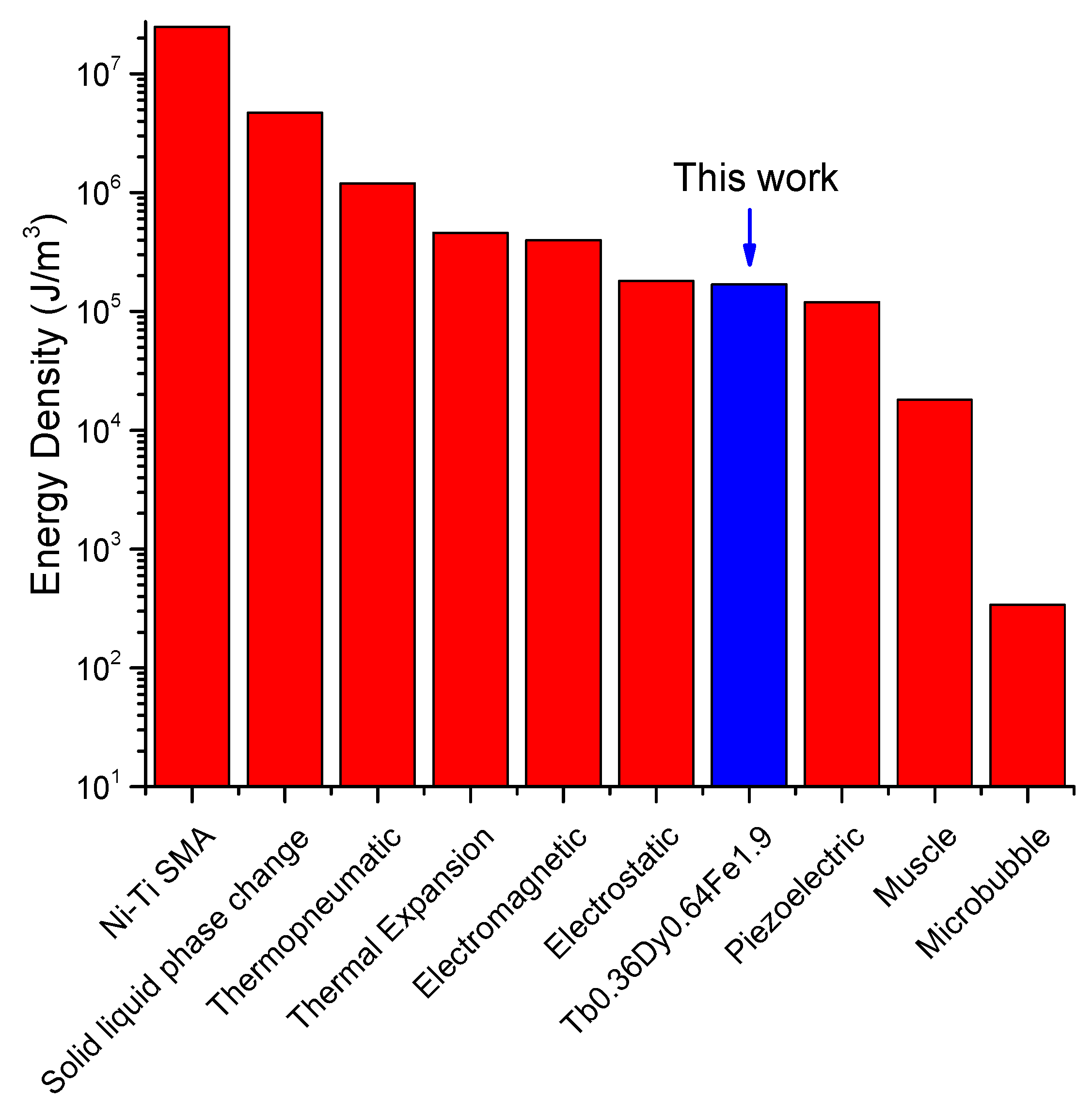
| Materials | Power Density |
|---|---|
| Bulk Terfenol-D | 5000 to 25,000 J/m3 |
| Tb0.36Dy0.64Fe1.9 (700 µm-long cantilever at 11 kOe) | 129,000 J/m3 |
| Tb0.36Dy0.64Fe1.9 (1000 µm-long cantilever at 11 kOe) | 169,000 J/m3 |
| Tb0.36Dy0.64Fe1.9 (1100 µm-long cantilever at 11 kOe) | 100,000 J/m3 |
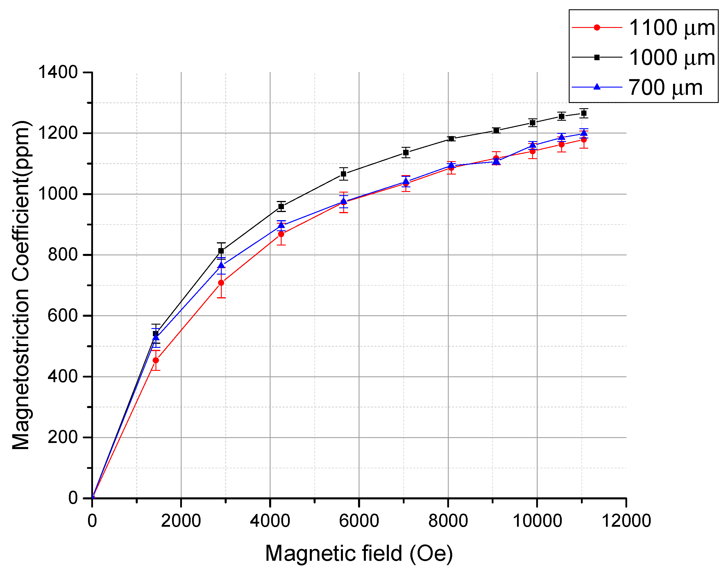
| Materials | Magnetostriction Coefficient (ppm) | Refs |
|---|---|---|
| Bulk Terfenol-D | 1400 | [1,2,7] |
| Electrodeposited Tb0.36Dy0.64Fe1.9 at 11 kOe | 1250 | This work |
| Sputtered Terfenol-D at 6 kOe | 450 | [24] |
| Sputtered Terfenol-D at 10 kOe | 540 | [23] |
| Sputtered Terfenol-D annealed 400 °C at 740 emu/cc | 910 | [20] |
| Sputtered Terfenol-D annealed 450 °C at 700 emu/cc | 880 | [19] |
| Electrodeposited Galfenol at 628 Oe | 96 | [6] |
| Bulk Galfenol | 320~400 | [5,6] |
| Sputtered Co0.66Fe0.34 annealed 800 °C | 260 | [11] |
| Electrodeposited Co0.65Fe0.35 | 1.5 | [9] |
| Bulk TbFe2 | 2630 | [1,2] |
© 2020 by the authors. Licensee MDPI, Basel, Switzerland. This article is an open access article distributed under the terms and conditions of the Creative Commons Attribution (CC BY) license (http://creativecommons.org/licenses/by/4.0/).
Share and Cite
Shim, H.; Sakamoto, K.; Inomata, N.; Toda, M.; Toan, N.V.; Ono, T. Magnetostrictive Performance of Electrodeposited TbxDy(1−x)Fey Thin Film with Microcantilever Structures. Micromachines 2020, 11, 523. https://doi.org/10.3390/mi11050523
Shim H, Sakamoto K, Inomata N, Toda M, Toan NV, Ono T. Magnetostrictive Performance of Electrodeposited TbxDy(1−x)Fey Thin Film with Microcantilever Structures. Micromachines. 2020; 11(5):523. https://doi.org/10.3390/mi11050523
Chicago/Turabian StyleShim, Hang, Kei Sakamoto, Naoki Inomata, Masaya Toda, Nguyen Van Toan, and Takahito Ono. 2020. "Magnetostrictive Performance of Electrodeposited TbxDy(1−x)Fey Thin Film with Microcantilever Structures" Micromachines 11, no. 5: 523. https://doi.org/10.3390/mi11050523
APA StyleShim, H., Sakamoto, K., Inomata, N., Toda, M., Toan, N. V., & Ono, T. (2020). Magnetostrictive Performance of Electrodeposited TbxDy(1−x)Fey Thin Film with Microcantilever Structures. Micromachines, 11(5), 523. https://doi.org/10.3390/mi11050523