Experimental Study on Machinability of Zr-Based Bulk Metallic Glass during Micro Milling


Abstract
1. Introduction
- Comparative study of the tool wear mechanism and its influence on the milled surface morphology of Zr-based BMG and an aluminum workpiece during the micro milling process;
- Uncovering the influence of milling parameters on surface roughness, milling force, and phase structure.
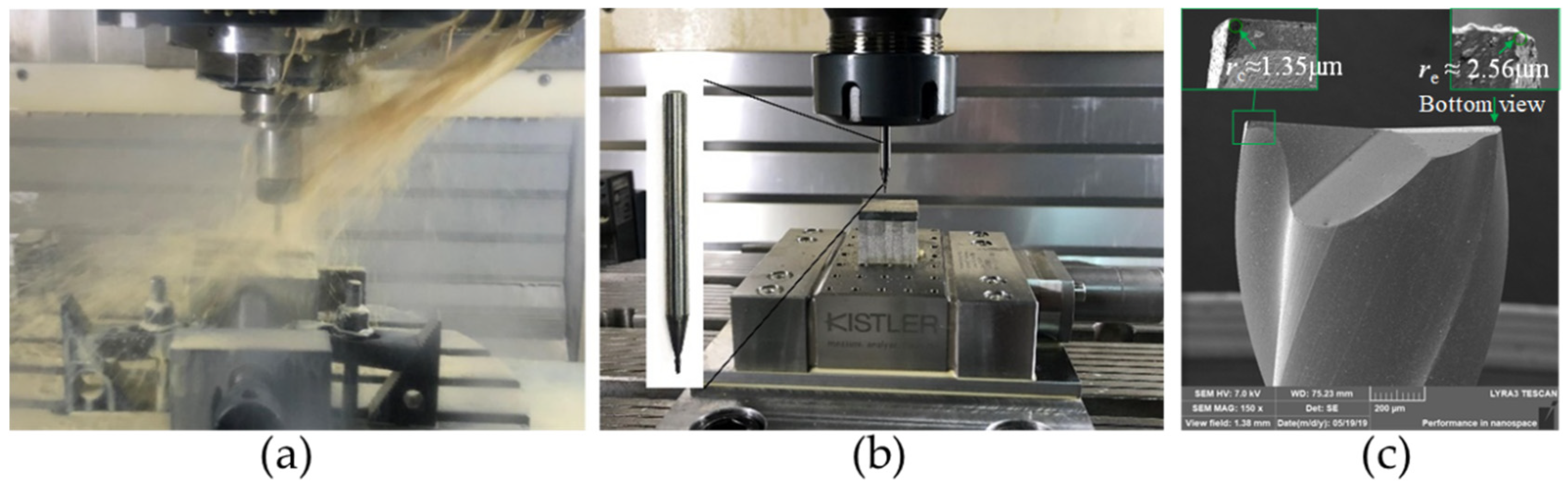
2. Materials and Methods
3. Results
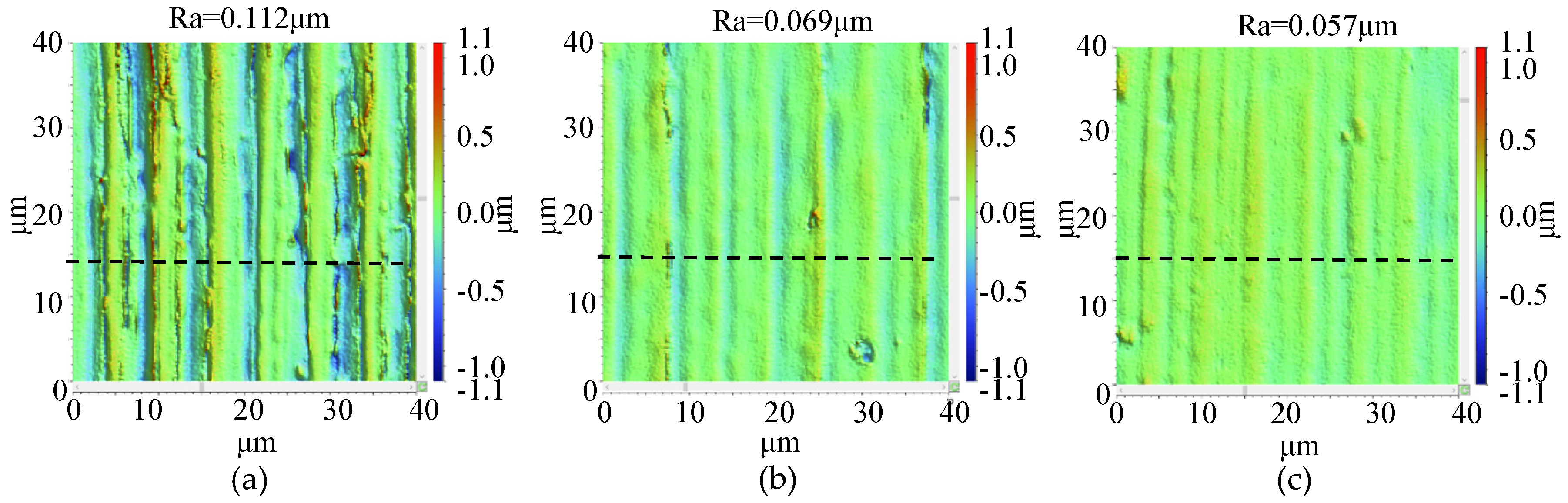
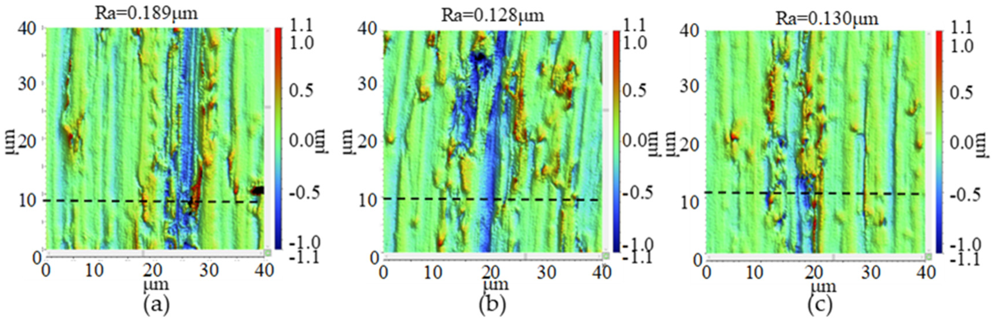
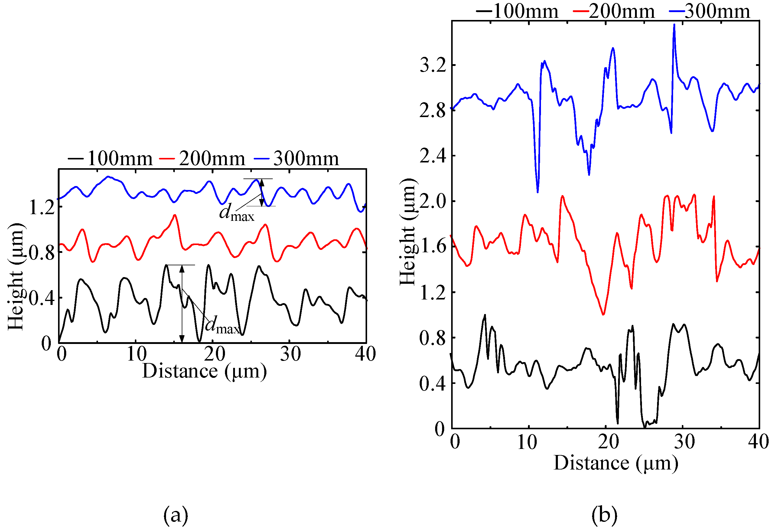
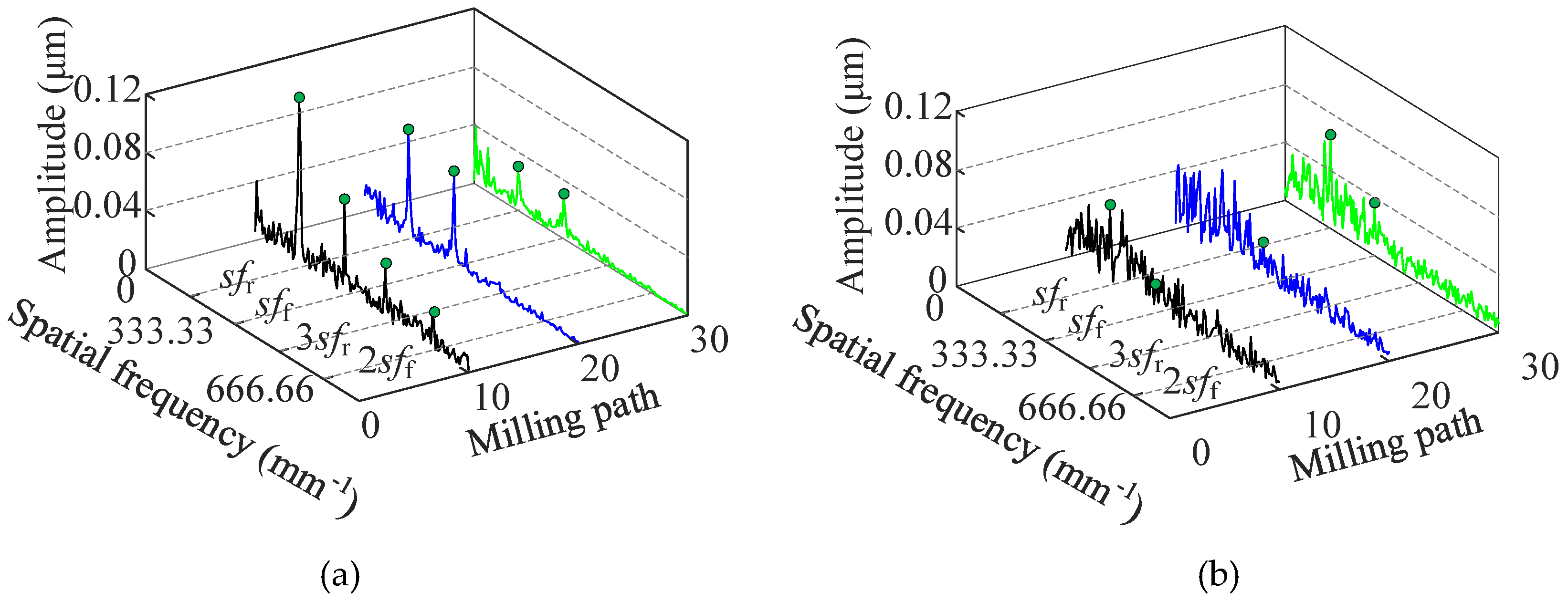
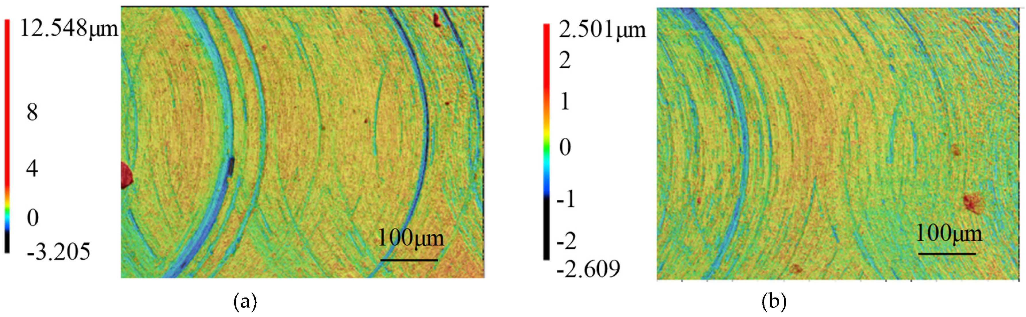
3.1. Surface Morphology
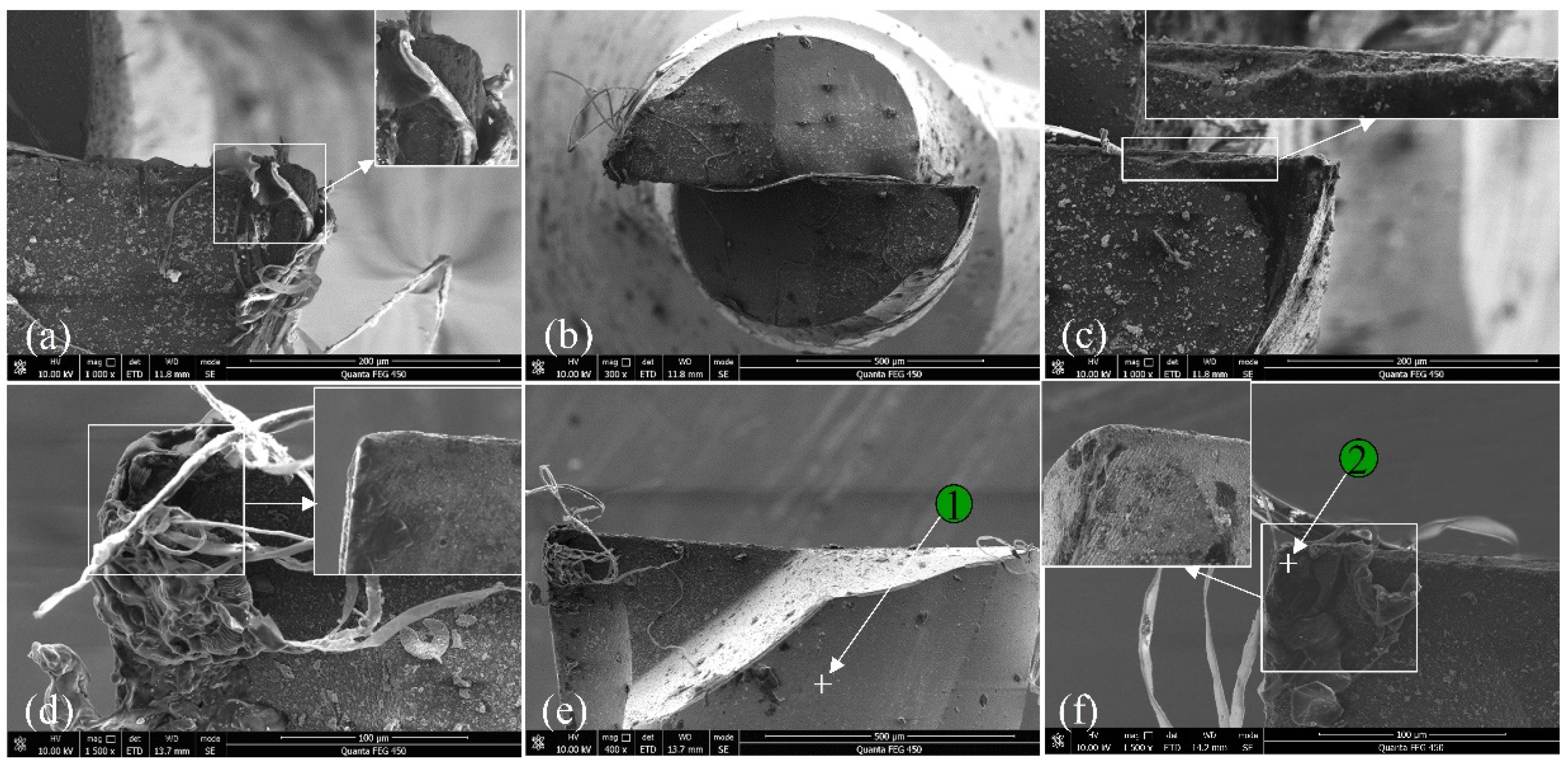
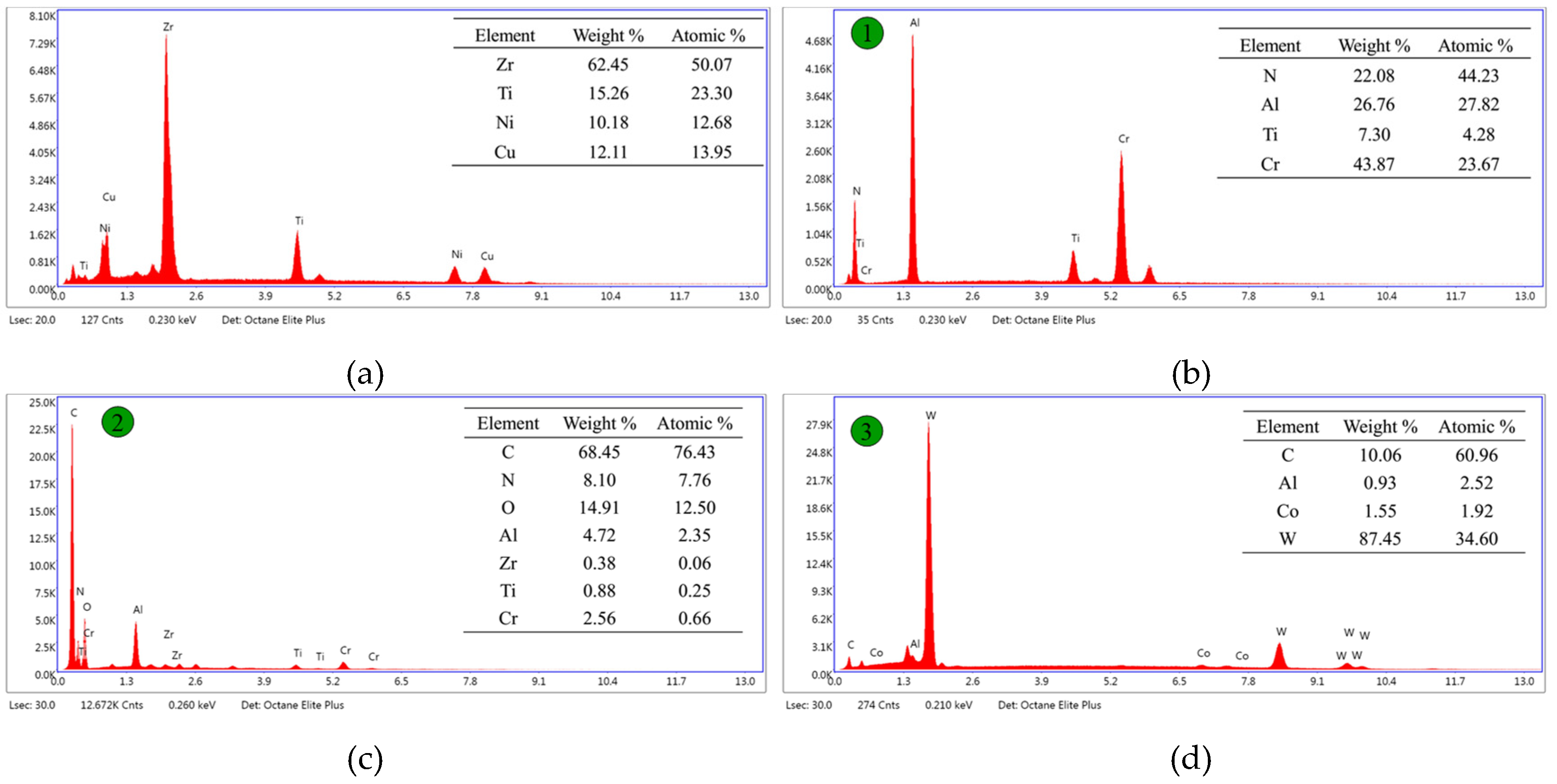
3.2. Tool Wear
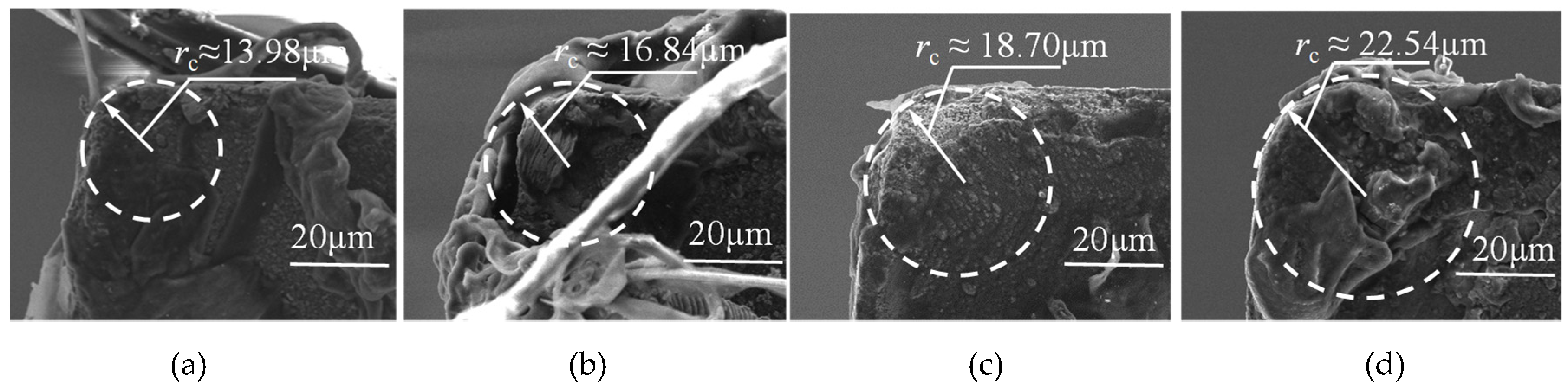
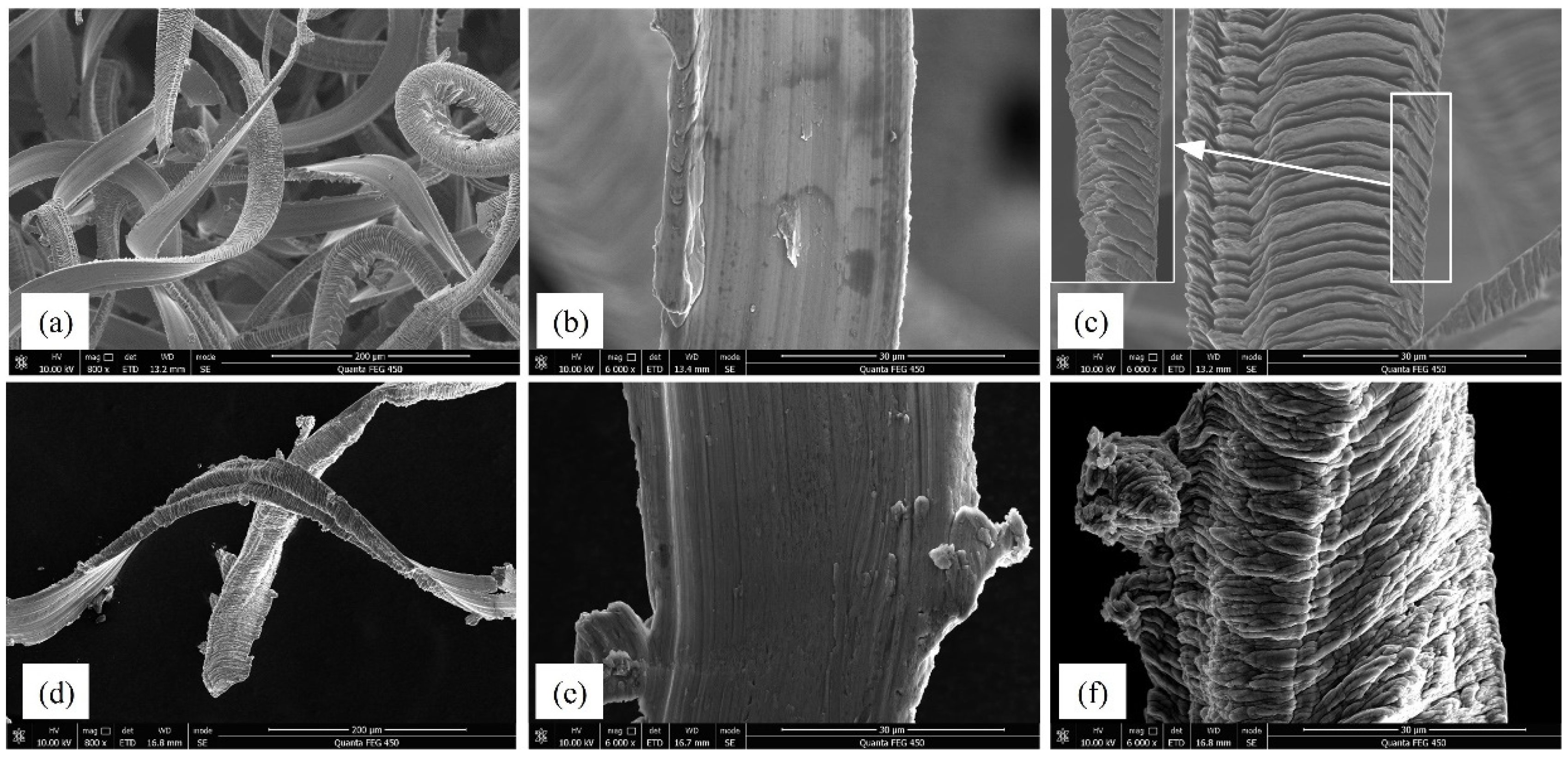
3.3. Chip Morphology
3.4. Surface Roughness
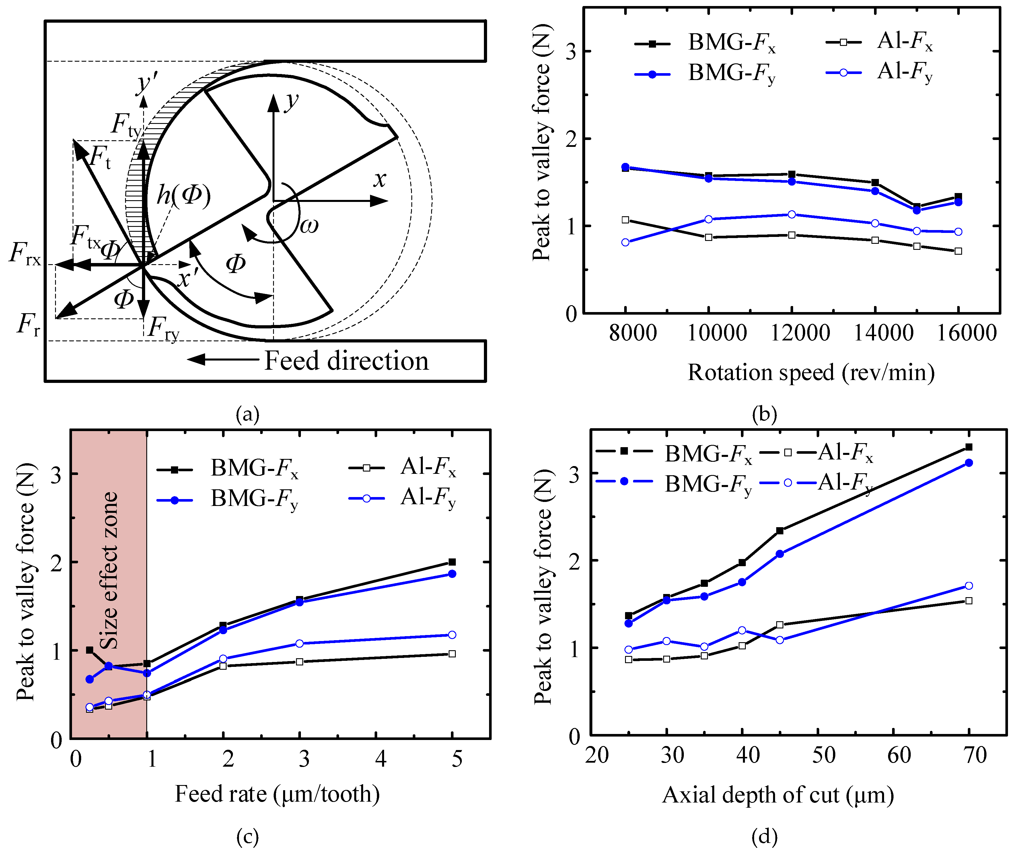
3.5. Milling Force
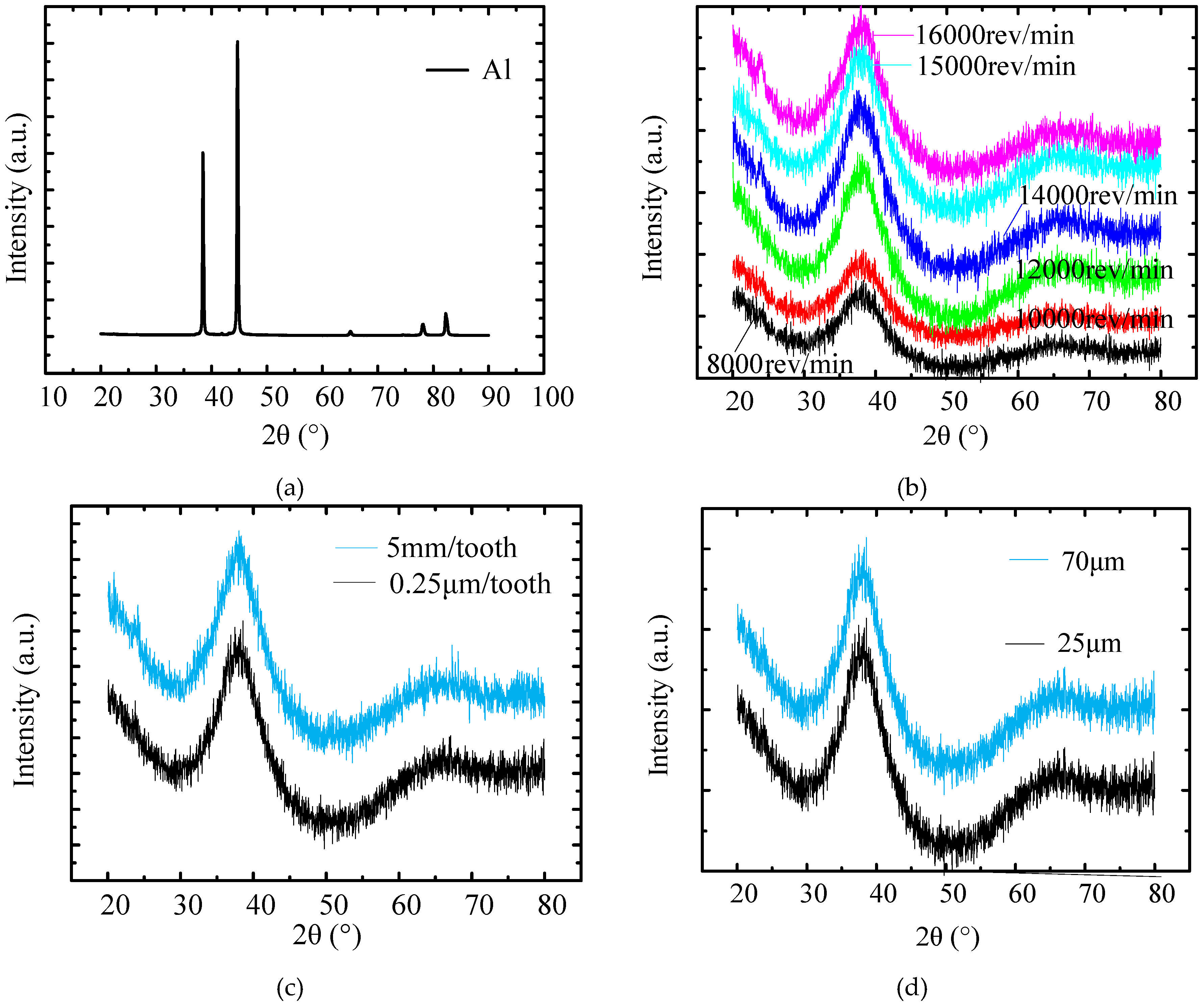
3.6. XRD Analysis
4. Discussion
4.1. Comparison between Zr-Based BMG and Stainless Steel
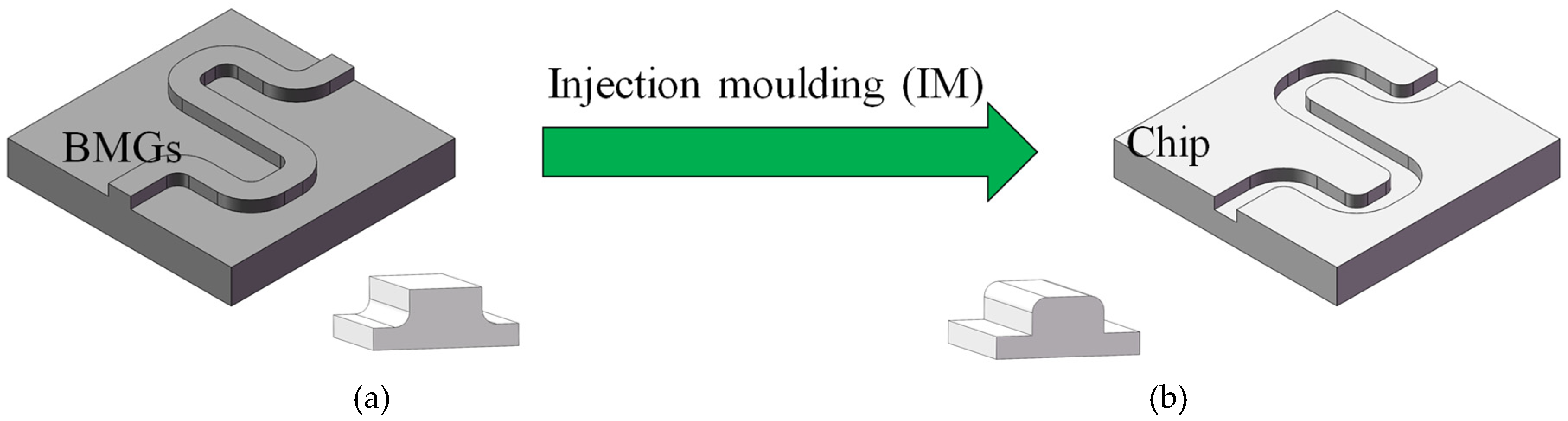
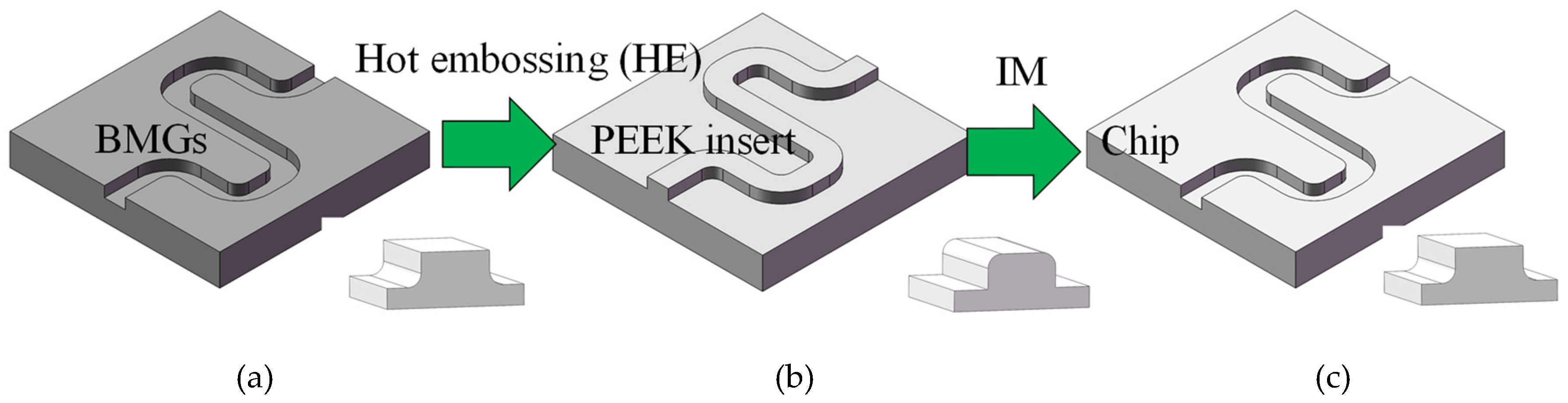
4.2. A Potential Application: Fabricating the Mold for Microfluidic Polymeric Devices
5. Conclusions
- The coated cemented tool was still in stable wear stage after milling Zr-based BMG for 300 mm, and the surface roughness Ra could be maintained around 0.06 μm. The tool experienced slight wear with small chipping and rubbing wear during milling the Zr-based BMG, while the built-up edge and coating peeling off occurred severely when milling Al6061.
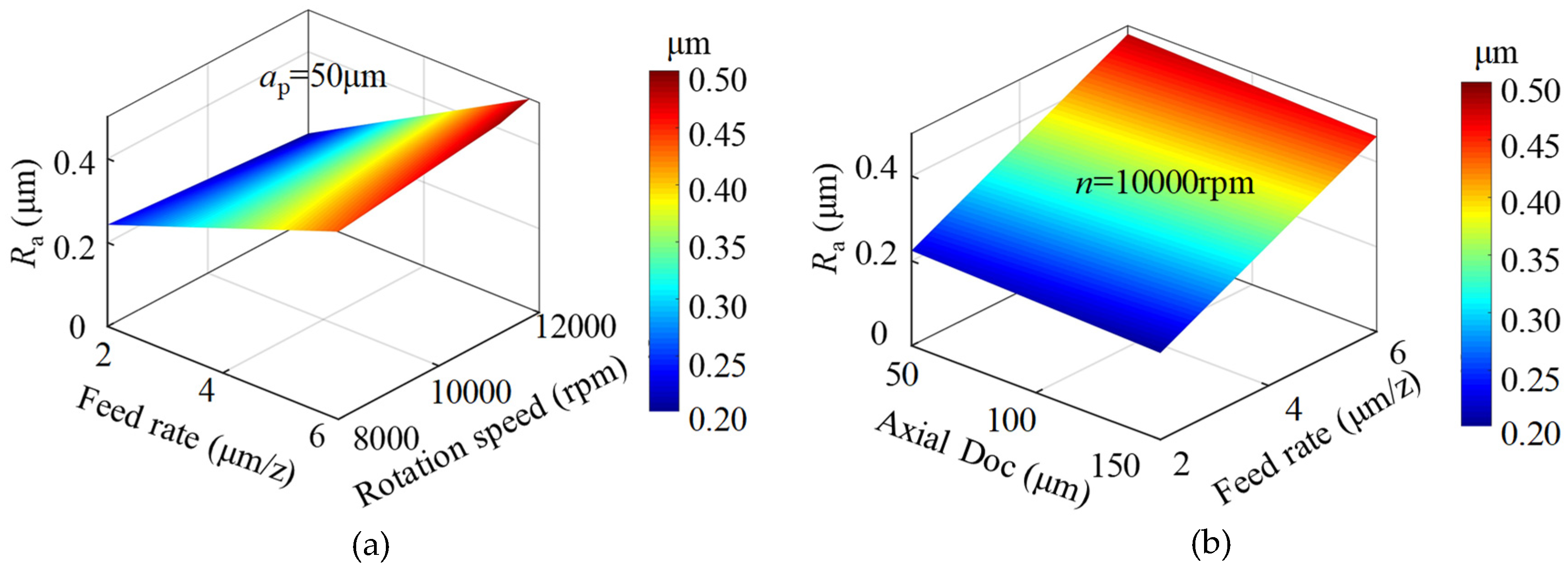
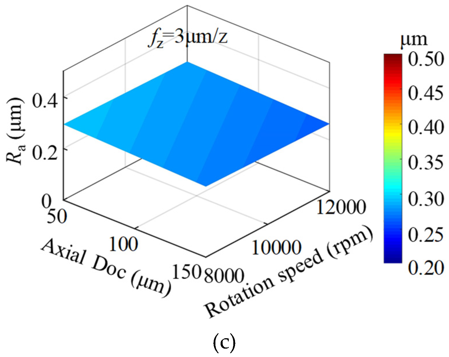
- As for the BMG material, the influence of rotation speed on surface roughness was insignificant, while surface roughness increased gradually with the increase in axial DOC. Surface roughness decreased with the reduction of feed rate, then increased sharply when the feed rate approached 2μm/tooth due to the size effect. All surface roughness values of milled BMG surfaces were much lower than those of milled aluminum surfaces with the same milling parameters.
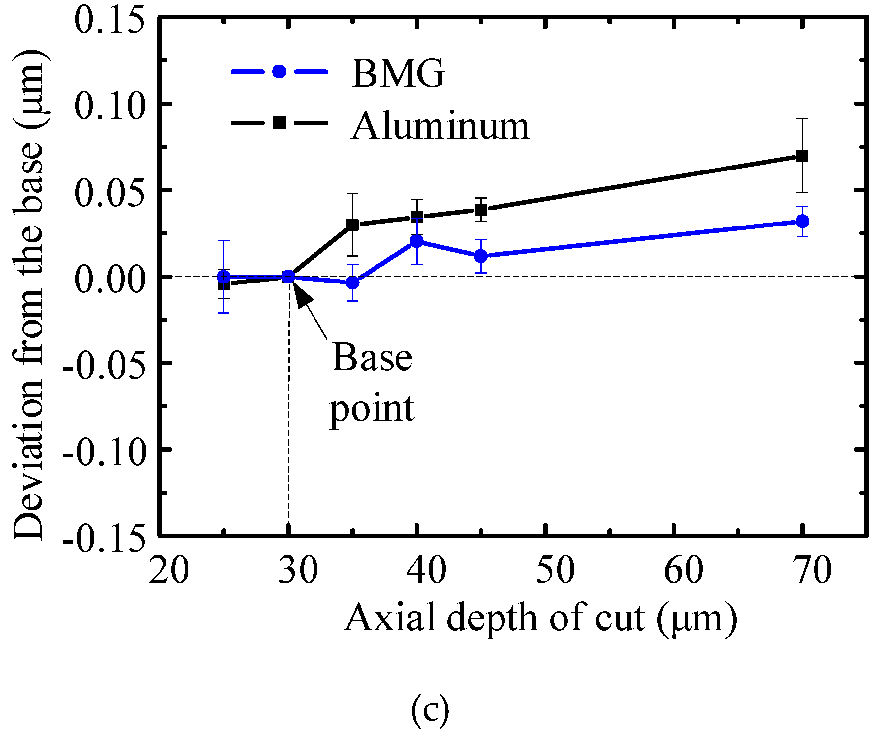
- As for the BMG material, milling force decreased slightly with rotation speed, while it increased rapidly with axial DOC. Milling force decreased linearly with the decrease in feed rate, while a nonlinear phenomenon occurred when the feed rate was below 1 μm/tooth. All milling forces of the BMG workpiece were higher than those of the aluminum workpiece with the same milling parameters.
- The X-ray diffraction testing results indicated that, under the milling parameters in this paper, all milled surfaces could still maintain the amorphous structure in dry machining conditions.
Author Contributions
Funding
Conflicts of Interest
References
- Trexler, M.M.; Thadhani, N.N. Mechanical properties of bulk metallic glasses. Prog. Mater. Sci. 2010, 55, 759–839. [Google Scholar] [CrossRef]
- Grimberg, A.; Baur, H.; Bochsler, P.; Bühler, F.; Burnett, D.S.; Hays, C.C.; Heber, V.S.; Jurewicz, A.J.G.; Wieler, R. Solar wind neon from Genesis: Implications for the lunar noble gas record. Science 2006, 314, 1133–1135. [Google Scholar] [CrossRef] [PubMed]
- Bakkal, M.; Shih, A.J.; Scattergood, R.O.; Liu, C.T. Machining of a Zr-Ti-Al-Cu-Ni metallic glass. Scr. Mater. 2004, 50, 583–588. [Google Scholar] [CrossRef]
- Bakkal, M.; Shih, A.J.; Scattergood, R.O. Chip formation, cutting forces, and tool wear in turning of zr-based bulk metallic glass. Int. J. Mach. Tool. Manu. 2004, 44, 915–925. [Google Scholar] [CrossRef]
- Bakkal, M.; Shih, A.J.; Mcspadden, S.B.; Liu, C.T.; Scattergood, R.O. Light emission, chip morphology, and burr formation in drilling the bulk metallic glass. Int. J. Mach. Tool. Manu. 2005, 45, 741–752. [Google Scholar] [CrossRef]
- Bakkal, M.; Shih, A.J.; Mcspadden, S.B.; Scattergood, R.O. Thrust force, torque, and tool wear in drilling the bulk metallic glass. Int. J. Mach. Tool. Manu. 2005, 45, 863–872. [Google Scholar] [CrossRef]
- Bakkal, M.; Naksiler, V. Cutting mechanics of bulk metallic glass materials on meso-end milling. Mater. Manuf. Process. 2009, 24, 1249–1255. [Google Scholar] [CrossRef]
- Jiang, M.Q.; Dai, L.H. Formation mechanism of lamellar chips during machining of bulk metallic glass. Acta Mater. 2009, 57, 2730–2738. [Google Scholar] [CrossRef]
- Fujita, K.; Morishita, Y.; Nishiyama, N.; Kimura, H.; Inoue, A. Cutting characteristics of bulk metallic glass. Mater. Trans. 2005, 46, 2856–2863. [Google Scholar] [CrossRef]
- Yan, Z.; Lu, J.; Yan, Z.; Wu, F.; Huo, D. Development of an analytical model based on mohr-coulomb criterion for cutting of metallic glasses. Int. J. Mech. Sci. 2016, 106, 168–175. [Google Scholar]
- Chen, X.; Xiao, J.; Zhu, Y.; Tian, R.; Shu, X.; Xu, J. Micro-machinability of bulk metallic glass in ultra-precision cutting. Mater. Des. 2017, 136, 1–12. [Google Scholar] [CrossRef]
- Dhale, K.; Banerjee, N.; Singh, R.K.; Outeiro, J.C. Investigation on chip formation and surface morphology in orthogonal machining of zr-based bulk metallic glass. Manuf. Lett. 2019, 19, 25–28. [Google Scholar] [CrossRef]
- Maroju, N.K.; Jin, X. Mechanism of chip segmentation in orthogonal cutting of zr-based bulk metallic glass. J. Manuf. Sci. Eng. 2019, 141, 081003. [Google Scholar] [CrossRef]
- Cheng, K.; Huo, D. Micro Cutting: Fundamentals and Applications; Wiley: Chichester, UK, 2013. [Google Scholar]
- Wan, M.; Wen, D.Y.; Ma, Y.C.; Zhang, W.H. On material separation and cutting force prediction in micro milling through involving the effect of dead metal zone. Int. J. Mach. Tools. Manuf. 2019, 146, 103452. [Google Scholar] [CrossRef]
- Yuan, Y.; Jing, X.; Ehmann, K.F.; Cao, J.; Li, H.; Zhang, D. Modeling of cutting forces in micro end-milling. J. Manuf. Process. 2018, 31, 844–858. [Google Scholar] [CrossRef]
- Wojciechowski, S.; Matuszak, M.; Powałka, B.; Madajewski, M.; Maruda, R.W.; Krolczyk, M. Prediction of cutting forces during micro end milling considering chip thickness accumulation. Int. J. Mach. Tools. Manuf. 2019, 147, 103466. [Google Scholar] [CrossRef]
- Wojciechowski, S.; Mrozek, K. Mechanical and technological aspects of micro ball end milling with various tool inclinations. Int. J. Mech. Sci. 2017, 134, 424–435. [Google Scholar] [CrossRef]
- Wojciechowski, S. Machined surface roughness including cutter displacements in milling of hardened steel. Metrol. Meas. Syst. 2011, 18, 429–440. [Google Scholar] [CrossRef]
- Maroju, N.K.; Yan, D.P.; Xie, B.; Jin, X. Investigations on surface microstructure in high-speed milling of Zr-based bulk metallic glass. J. Manuf. Process. 2018, 35, 40–50. [Google Scholar] [CrossRef]
- Grossi, N.; Scippa, A.; Sallese, L.; Montevecchi, F.; Campatelli, G. On the generation of chatter marks in peripheral milling: A spectral interpretation. Int. J. Mach. Tool. Manu. 2018, 133, 31–46. [Google Scholar] [CrossRef]
- Wang, R.; Wang, B.; Barber, G.C.; Gu, J.; Schall, J.D. Models for prediction of surface roughness in a face milling process using triangular inserts. Lubricants 2019, 7, 9. [Google Scholar] [CrossRef]
- de Oliveira, F.B.; Rodrigues, A.R.; Coelho, R.T.; de Souza, A.F. Size effect and minimum chip thickness in micromilling. Int. J. Mach. Tool. Manu. 2015, 89, 39–54. [Google Scholar] [CrossRef]
- Huang, L.; Pu, C.; Fisher, R.K.; Mountain, D.J.H.; Gao, Y.F.; Liaw, P.K.; Zhang, W.; He, W. A zr-based bulk metallic glass for future stent applications: Materials properties, finite element modeling, and in vitro human vascular cell response. Acta Biomater. 2015, 25, 356–368. [Google Scholar] [CrossRef] [PubMed]
- Lee, W.S.; Chen, T.H.; Lin, C.F.; Luo, W.Z. Dynamic mechanical response of biomedical 316L stainless steel as function of strain rate and temperature. Bioinorg. Chem. Appl. 2011, 2011, 1–13. [Google Scholar] [CrossRef] [PubMed]
- Morrison, M.L.; Buchanan, R.A.; Leon, R.V.; Liu, C.T.; Green, B.A.; Liaw, P.K. The electrochemical evaluation of a zr-based bulk metallic glass in a phosphate-buffered saline electrolyte. J. Biomed. Mater. Res. A 2005, 74, 430–438. [Google Scholar] [CrossRef] [PubMed]
- Kuram, E.; Ozcelik, B. Micro-milling performance of aisi 304 stainless steel using taguchi method and fuzzy logic modelling. J. Intell. Manu. 2016, 27, 817–830. [Google Scholar] [CrossRef]
- Zhang, N.; Srivastava, A.P.; Browne, D.J.; Gilchrist, M.D. Performance of nickel and bulk metallic glass as tool inserts for the microinjection molding of polymeric microfluidic devices. J. Mater. Process. Technol. 2016, 231, 288–300. [Google Scholar] [CrossRef]
- Leu, T.S.; Chang, P.Y. Pressure barrier of capillary stop valves in micro sample separators. Sens. Actuator A Phys. 2004, 115, 508–515. [Google Scholar] [CrossRef]
- Griffiths, C.A.; Bigot, S.; Brousseau, E.; Worgull, M.; Heckele, M.; Nestler, J.; Auerswald, J. Investigation of polymer inserts as prototyping tooling for micro injection moulding. Int. J. Adv. Manuf. Technol. 2010, 47, 111–123. [Google Scholar] [CrossRef]


| Single Factor | Rotation Speed (rpm) | Cutting Speed (m/min) | Feed Rate (μm/tooth) | Depth of Cut (μm) |
|---|---|---|---|---|
| Rotation speed | 8000, 10,000, 12,000, 14,000, 15,000, 16,000 | 25, 31, 38, 44, 47, 50 | 3 | 30 |
| Feed rate | 10,000 | 31 | 0.25, 0.5, 1, 2, 3, 5 | 30 |
| Axial depth of cut | 10,000 | 31 | 3 | 25, 30, 35, 40, 45, 70 |
| Mechanical Properties | 316L | Zr-Based BMG |
|---|---|---|
| Tensile yield strength (MPa) | 190–690 | 1900 |
| Elastic strain limit (%) | 0.34 | 2.0–2.2 |
| Young’s modulus (GPa) | 193–210 | 90 |
| Hardness (Vickers) | 365 | 590 |
| Fatigue limit at 107 cycles (MPa) | 200–800 | 910 |
| Density (g/cm3) | 7.9 | 5.9 |
© 2020 by the authors. Licensee MDPI, Basel, Switzerland. This article is an open access article distributed under the terms and conditions of the Creative Commons Attribution (CC BY) license (http://creativecommons.org/licenses/by/4.0/).
Share and Cite
Wang, T.; Wu, X.; Zhang, G.; Xu, B.; Chen, Y.; Ruan, S. Experimental Study on Machinability of Zr-Based Bulk Metallic Glass during Micro Milling. Micromachines 2020, 11, 86. https://doi.org/10.3390/mi11010086
Wang T, Wu X, Zhang G, Xu B, Chen Y, Ruan S. Experimental Study on Machinability of Zr-Based Bulk Metallic Glass during Micro Milling. Micromachines. 2020; 11(1):86. https://doi.org/10.3390/mi11010086
Chicago/Turabian StyleWang, Tao, Xiaoyu Wu, Guoqing Zhang, Bin Xu, Yinghua Chen, and Shuangchen Ruan. 2020. "Experimental Study on Machinability of Zr-Based Bulk Metallic Glass during Micro Milling" Micromachines 11, no. 1: 86. https://doi.org/10.3390/mi11010086
APA StyleWang, T., Wu, X., Zhang, G., Xu, B., Chen, Y., & Ruan, S. (2020). Experimental Study on Machinability of Zr-Based Bulk Metallic Glass during Micro Milling. Micromachines, 11(1), 86. https://doi.org/10.3390/mi11010086