1. Introduction
In the past decades, acoustic metamaterial has aroused a tremendous interest in lots of potential applications, including acoustic super-lensing/hyper-imaging, beam steering, and cloaking [
1,
2,
3]. In particular, phononic crystal (PnC) is a remarkable example of acoustic metamaterials due to its salient trait, such as vibration attenuation/isolation, wave filter, localization, and acoustic wave guide [
4,
5,
6]. For this reason, PnC has been rapidly developed, while it is fast growing in physics and engineering communities today. Besides, micro-electro-mechanical systems (MEMS) technologies have shown promising prospects in wireless communication systems and sensor networks [
7,
8]. More specifically, silicon-based MEMS resonators offer attractive features in complementary metal oxide semiconductor (CMOS) process compatibility, as well as high power handling capacity [
9]. Furthermore, aluminum nitride (AlN) piezoelectric thin film exhibits a high phase velocity, weak phase velocity dispersion, and moderate electromechanical coupling coefficient (
k2eff) [
10]. Consequently, the AlN-on-Silicon MEMS resonator is a satisfactory technology for single-chip multi-band wireless communications [
11].
In the MEMS resonator-based applications, a high-quality factor (
Q) is highly desirable for achieving low phase noise and high frequency stability as oscillators, and realizing low insertion loss as filters [
12]. Up to date, various energy loss reduction strategies for piezoelectric MEMS resonators to improve
Q have been proposed and aroused much attention [
13,
14,
15,
16,
17,
18]. Moreover, exploiting one-dimensional (1D) or two-dimensional (2D) PnC in tethers or surrounding the resonant body of resonators is an effective technology to significantly reduce the anchor loss [
19,
20,
21,
22,
23,
24,
25]. Even so, one of the critical challenges of PnC applied in resonators still faced by researchers is the large lattice constant compared to the associated acoustic wavelength. For instance, the resonant frequency of the fundamental width extensional (WE) lamb mode is decided by the half-wavelength width of the resonant body. Meanwhile, Bragg scattering acoustic bandgaps occur at wavelengths of the order of the PnC unit cell size in general [
26], thus it is still difficult to exploit small-sized PnC arrays in a highly integrated MEMS device to greatly improve its performance. Given this, it is highly urgent to develop a PnC structure, with the following features of a small lattice constant, lightweight, and wide acoustic bandgaps, to enable the miniaturization of MEMS devices.
In addition, the structural behavior of orb spider webs, which is inspired by natural materials, has been studied under quasi-static and dynamic loading conditions [
27,
28,
29]. Another silk-based spider-web structure designed as a PnC structure was firstly proposed, and its propagation characteristics of elastic waves were numerically studied [
30]. However, it was found that the silk-based spider web-like PnC (
SW-PnC) structure with a square outframe in [
30] could not form any complete acoustic bandgaps in the MHz frequency range. Meanwhile, the
SW-PnC structure has yet to be utilized for anchor loss reduction in silicon-based MEMS resonators. Thereby, we optimized the
SW-PnC structure to successfully form three complete bandgaps in the MHz frequency range, and then applied it in MEMS resonators to reduce the acoustic energy dissipation.
In this research, a PnC unit cell with a large circle hole (
C-PnC) was selected, because of its already very lightweight PnC structure compared with previously reported PnCs (i.e., ring-shaped PnC, cross-shaped PnC, fractal-like PnC, etc.) [
19,
31], to compare the lattice constant (a), weight, and energy loss suppression in a similar bandgap frequency range with
SW-PnC. Subsequently, multiphysics finite-element-analysis (FEA) simulations of the delay line and solid line with finite PnC periods, and with the reference solid silicon slab as the transmission mediums between interdigital transducers (IDTs) were performed, verifying the existence of acoustic bandgaps that can be formed by the associated PnC structure with infinite periods and varying abilities of acoustic wave isolation for different PnCs. Finally, three types of MEMS resonators, including the conventional resonator (C), the resonator with
C-PnC array plates (RCP), and that with
SW-PnC array plates (RSWP) were designed to further verify the effectiveness of finite PnC structure in reducing the anchor loss and indicate that the resonator RSWP could realize the optimal
Q.
2. Phononic Crystals Design
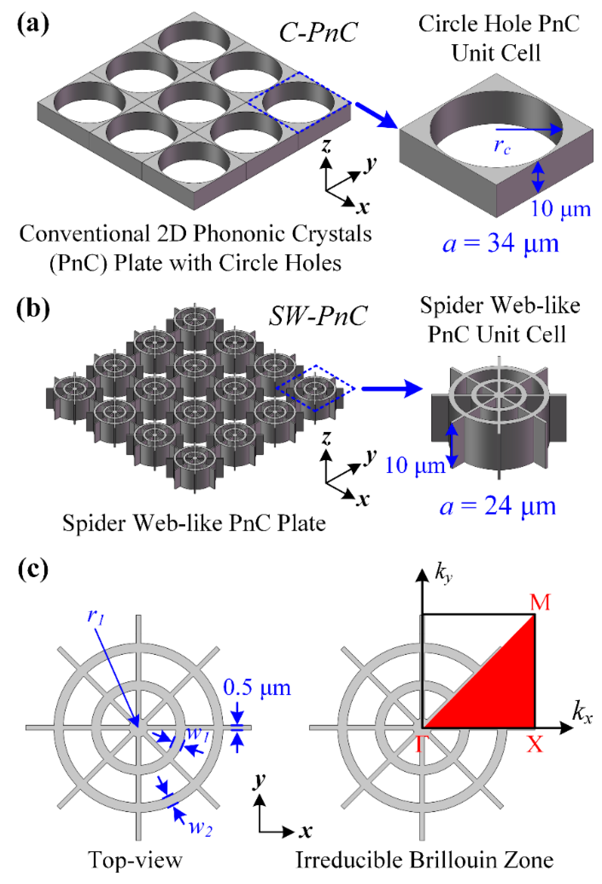
Figure 1 shows the 3D models of two types of PnC plate containing a 2D PnC plate with circle holes and a 2D spider web-like PnC plate. In order to utilize these PnC structures in MEMS resonators in this research, the PnCs were made of the most commonly used anisotropic single crystalline silicon [
32] and the thickness of PnC structures was fixed as 10 μm. As shown in
Figure 1, the default
x axis,
y axis, and
z axis was set as the (110), (–110), and (001) direction of a standard (100) direction silicon wafer. Moreover, the elasticity values of the single crystalline silicon in this research were defined as:
where the
E,
σ, and
G are the Young’s modulus, Poisson’s ratio, and shear modulus of the adopted single crystalline silicon, respectively. Besides, the values of mass density (
ρ) and acoustic velocity (
v) of silicon are 2330 kg/m
3 and 8500 m/s, respectively.
To simultaneously obtain a similar frequency range and width of the acoustic bandgap formed by the proposed PnCs, the geometry parameters of the radius (rc) and lattice constant (a) of the circle hole PnC (C-PnC) unit cell were designed as 16.5 and 34 μm, respectively. Moreover, the radius (r1) of the circle, width of the narrow beams, and width of the rings (w1, w2) of the spider web-like PnC (SW-PnC) unit cell were defined as 24, 1, 0.5, 2, and 2 μm, respectively. In general, in comparison with the 3 × 3 C-PnC array (102 μm × 102 μm), the proposed 4 × 4 SW-PnC array (96 μm × 96 μm) has an approximate size but offers a lighter weight and greater ability of acoustic wave isolation (i.e., which will be demonstrated later). In addition, the proposed SW-PnC works around the frequency range of 76 MHz. For other frequency ranges, the in-plane dimension size of the lattice constant and radii of the circles for the PnC unit cell can be reduced or enlarged proportionally. Changing the width of the beams is not recommended, as this width would be likely set at the minimum width imposed by the fabrication process. Besides, the SW-PnC is difficult to fabricate due to its large thicknesses/aspect ratios in the current Bosch process. So, the SW-PnC is at present suggested to enlarge the in-plane size to reduce the thicknesses/aspect ratios, and then use it in some lower frequency applications.
In this research, the propagation characteristics of acoustic waves of PnCs were systematically investigated by using the COMSOL (5.4, COMSOL, Inc., Burlington, MA, USA) multiphysics finite-element analysis. Specifically, wave dispersion relations in an infinite PnC lattice were studied by applying Floquet periodic boundary conditions at the unit cell boundaries, while performing a parametric sweep in the wave vector,
k, along the borders of Γ-X-M-Γ for the first irreducible brillouin zone as depicted in
Figure 1c. Furthermore, to verify that acoustic bandgaps can be formed by the associated PnC structure, transmission parameters (i.e., S21) were introduced in the PnC-based delay line and solid line to quantify the acoustic wave isolation, and the S21 in decibels was expressed as:
where
Pout and
Pin are the values of the output and input power in the delay line and solid line, respectively. The initial
Pin was 0 dBm. Moreover, S21 is the S-parameter of transmitted waves, and represents the power transmission coefficient from the input port to the output port. Consequently, the proposed multiphysics finite-element analysis (FEA) simulation models of the delay line and solid line can be used to map the mechanical quantities to electrical ones, and further prove the transmission properties of PnCs.
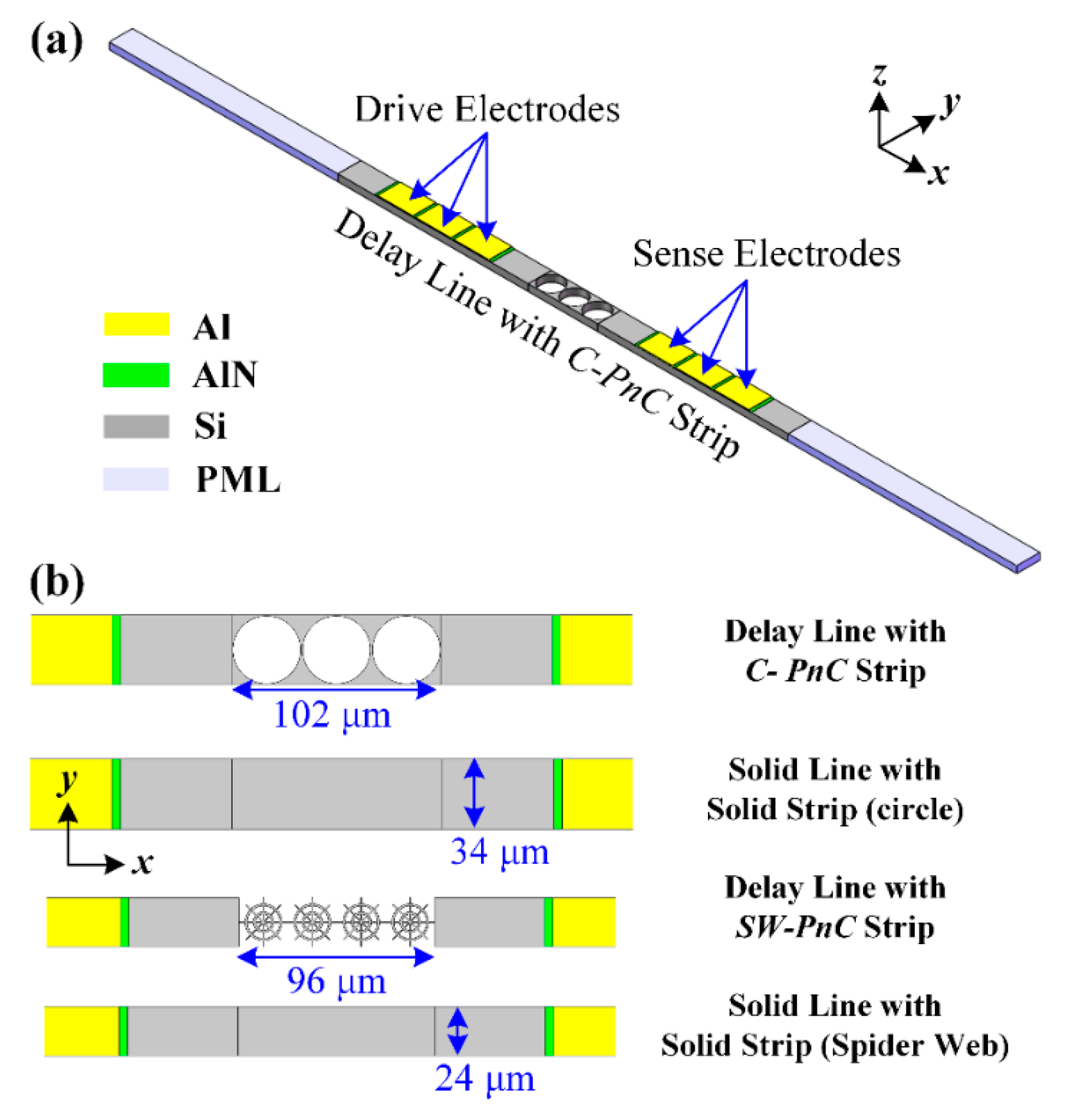
As shown in
Figure 2a, a delay line has finite PnC periods as the transmission medium between the drive and sense interdigitated transducers (IDTs), and the piezoelectric thin film is (AlN, 0.5 μm thick) sandwiched between the IDTs (Al, 1 μm thick) and the silicon substrate (single crystalline silicon, 10 μm thick). Besides, the solid line was designed by the PnC strip in the delay line, which replaces the solid slab. To avoid unexpected spurious peaks being stimulated in the transmission spectra by reflected waves, perfectly matched layers (PMLs) were introduced at the ends of the delay line and solid line. As shown in
Figure 2, the width (
y-direction) of the delay line and solid line was equal to the lattice constant (
a) of the associated PnC while the length of PMLs (
x-direction) was set as the 3-fold wavelength (3
λ). In the meantime, in order to form a 2D PnC slab and improve the calculation efficiency, periodic boundary conditions were applied to surfaces along the
y-direction of the delay line and solid line.
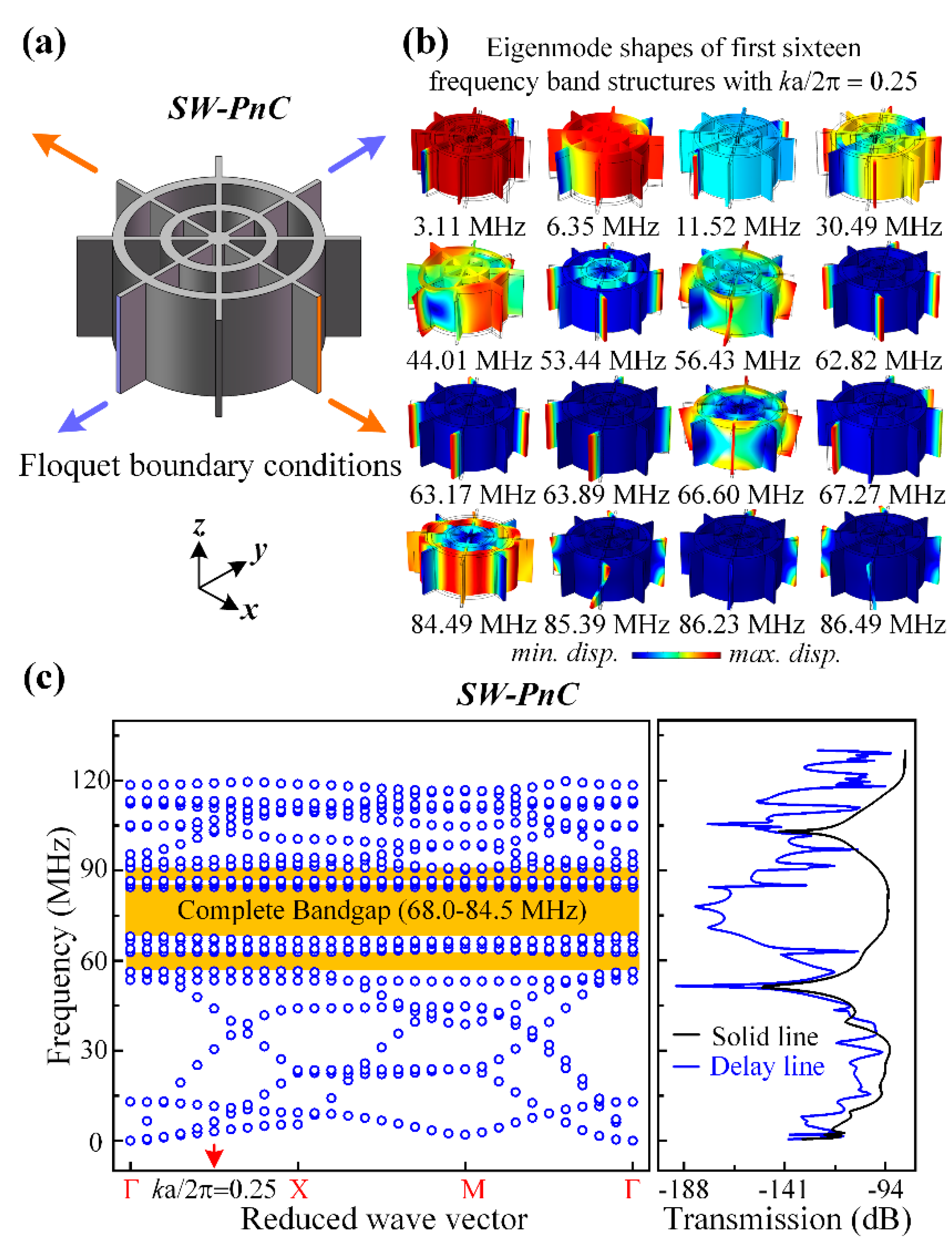
Figure 3 and
Figure 4 present the band structures and transmission properties of the proposed PnCs. As shown in
Figure 3a and
Figure 4a, the Flouqet periodic boundary conditions were applied to a C-PnC unit cell and SW-PnC unit cell, respectively. Specifically, the boundary condition applied on the orange surfaces means an infinite number of repetitions in the
x-direction, and the condition applied on the purple surfaces means an infinite number of repetitions in the
y-direction. Moreover, the dispersion relations of C-PnC shows one complete acoustic bandgap in the frequency range from 67.7 to 83.5 MHz. The corresponding eigenmode shapes of the C-PnC of the first 10 frequency band structures with
ka/2π = 0.25 are displayed in
Figure 3b. Furthermore, as shown in
Figure 4, the SW-PnC shows three complete bandgaps, and the widest frequency range of these is from 68.0 to 84.5 MHz. Subsequently, the corresponding eigenmode shapes of the SW-PnC of the first 16 frequency band structures with ka/2π = 0.25 are displayed in
Figure 4b.
To investigate the peculiarity of the
SW-PnC and verify that acoustic bandgaps can be formed by the proposed PnCs, transmission parameters (i.e., S21) of the delay line with four periods of the
SW-PnC strip, the solid line with the solid strip (
SW-PnC), delay line with three periods of the
C-PnC strip, and the solid line with the solid strip (
C-PnC) were performed. As shown in
Figure 3c and
Figure 4c, the FEA simulation result illustrates the wave attenuation mechanism in the transmission spectra, which is consistent with the associated acoustic bandgaps. It is noteworthy that the bandgap of PnC for out-of-plane modes is a partial bandgap for in-plane modes. For instance, as shown in
Figure 3b,c, the last two frequency band structures of
C-PnC are the out-of-plane mode, which means an in-plane bandgap can be achieved between the frequency of 104.23 MHz and the frequency of 123.83 MHz. Therefore, a wave attenuation mechanism can be observed at the frequency range round 120 MHz.
Herein, to measure the performance of associated PnC, the bandwidth BG% was introduced in this research and can be defined as the gap to mid-gap ratio [
33]:
where
fup and
fdown are the bounding frequencies of the acoustic bandgap. In this research, the frequency range of the complete bandgap for
C-PnC is from 67.7 to 83.5 MHz and the frequency range of the largest complete bandgap for
SW-PnC is from 68.0 to 84.5 MHz. Apparently, the mid-gap frequency of
C-PnC is approximately equal as 76 MHz to that of
SW-PnC. The BG% of
C-PnC and
SW-PnC is 20.9% and 21.6%, respectively. In general, the proposed
SW-PnC possesses a smaller lattice constant (70.6%) and much lighter weight (44.2%) in a similar bandgap frequency range compared with
C-PnC.
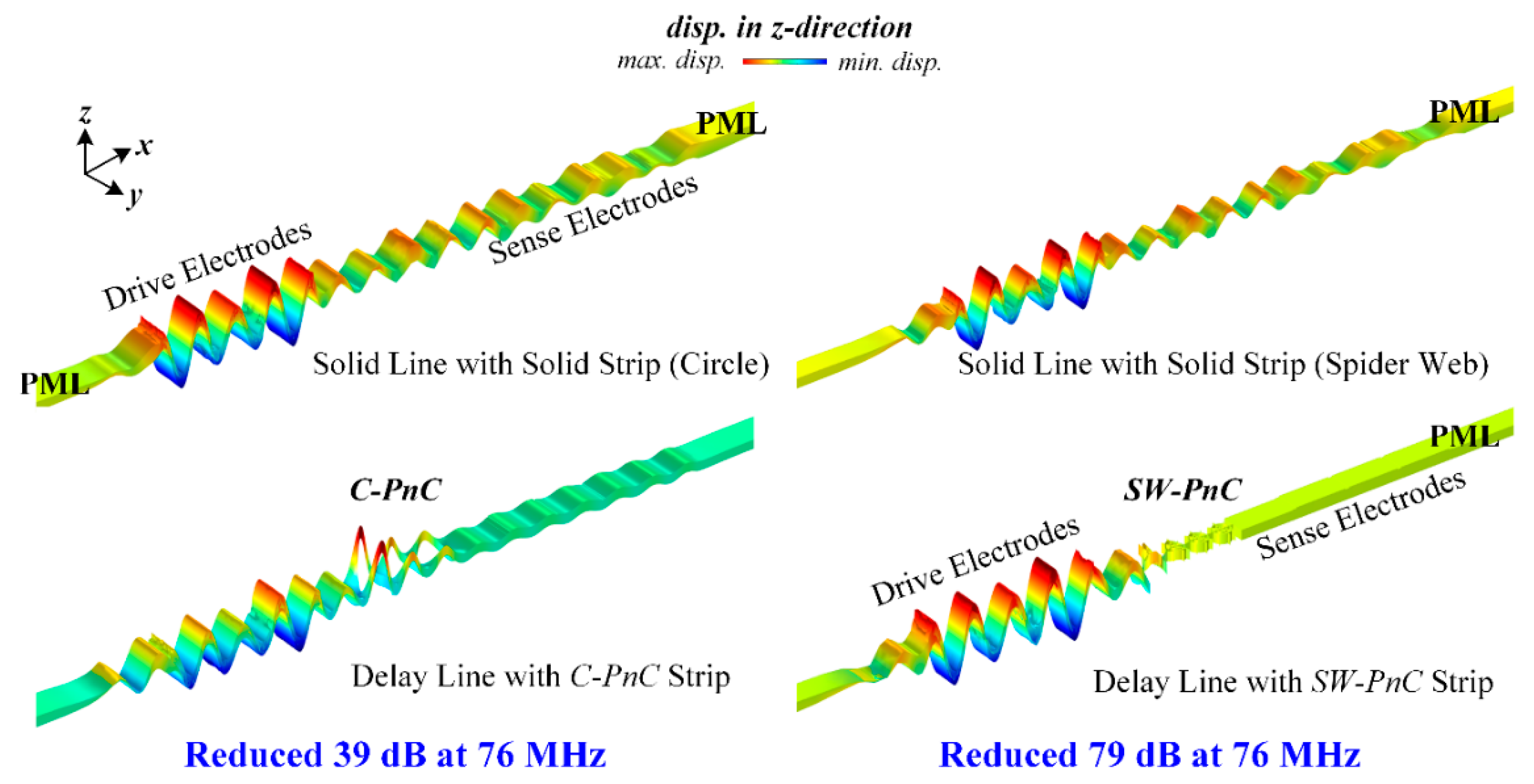
Figure 3c and
Figure 4c show that the two PnC structures have a similar frequency range of acoustic bandgaps, but
SW-PnC has a more significant isolation of acoustic waves. As illustrated in
Figure 5, more insight into the wave isolation in the proposed PnCs is achieved by analyzing the displacement distribution in the
z-direction of two types of delay line and solid line working at the frequency of 76 MHz. The left part of
Figure 5 shows that the
C-PnC strip can only suppress part of the acoustic wave propagation, indicating that it will still have a nonnegligible energy loss if applied in the MEMS resonator. As shown in the right of
Figure 5, since the
SW-PnC strip is applied in the delay line, the PnC transmission medium effectively prohibits the propagation of waves generated from the drive IDTs. In particular, the displacement amplitude in the
z-direction in the domain of the sense electrodes is approximately zero, which means the
SW-PnC strip can completely suppress the propagation of acoustic waves. Furthermore, through a numerical calculation of the simulation results, the delay line with the
SW-PnC strip is reduced by 79 dB and the delay line with the
C-PnC strip is only reduced by 39 dB at the same frequency of 76 MHz compared with that of the associated reference solid line, suggesting that a more significant (i.e., two-fold) reduction of energy loss was achieved by the
SW-PnC.
In addition, it is worth noting that the minimum width in a single PnC cell (0.5 μm) is not the minimum width in the
C-PnC array, which is a series of repeated cells. The minimum width of the
C-PnC array is twice the minimum width of 0.5 μm. However, the minimum width of the
SW-PnC array (0.5 μm) is the same as that of the
SW-PnC unit cell. Given this, the acoustic bandgap of the
C-PnC unit cell with a minimum width of 0.25 μm was calculated. As shown in
Figure 6, to make the bandgap be in a similar frequency range, the lattice constant and radius of the circle hole of the
C-PnC unit cell with a 0.25-μm minimum width was designed as 32 μm and 15.75 μm, respectively. Moreover, as shown in
Figure 6b, the BG% of the
C-PnC with a minimum width of 0.25 μm increased to 28.1%. Nevertheless, in comparison with the
C-PnC (0.25 μm minimum width), the proposed
SW-PnC still shows a smaller lattice constant (75%) and lighter weight (54.3%) with the same mid-gap frequency of 76 MHz. In this research, we were more focused on discussing the minimum width of the
SW-PnC unit cell and
C-PnC unit cell being the same as 0.5 μm. Thereby, the following discussions about the application of
C-PnC in MEMS resonators is based on the 0.5-μm minimum width.
3. Resonators Design
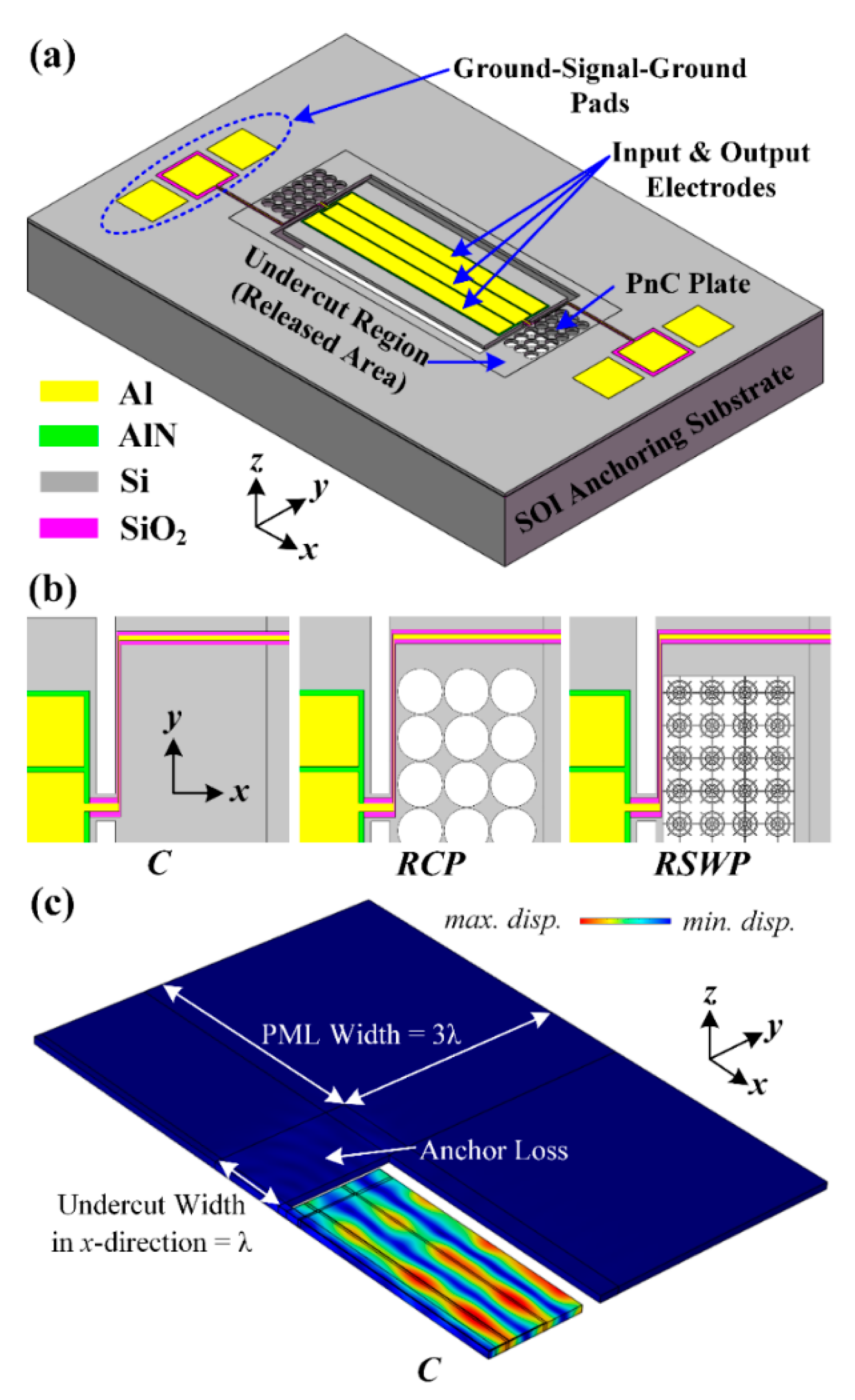
In order to further demonstrate the effectiveness of the proposed PnCs, as illustrated in
Figure 7a,b, PnC array plates as the anchoring boundaries were designed in an AlN-on-SOI MEMS resonator to improve the quality factor (
Q) by reducing the anchor loss compared with the conventional MEMS resonator. In this research, the center-to-center electrode pitch (W
p) of resonators was set as 56 µm, and designed to be transduced at the fifth-order symmetric lamb mode, which resonates at the frequency of 76 MHz. The resonant frequency of resonators for any given harmonic mode is given by [
34]:
where
Wr is the width of the resonator and
n is the number of harmonic modes. For a fifth-order symmetric mode of resonators, the
Wr is equal to the five-fold W
p (i.e., W
r = 5 W
p).
Moreover, three types of MEMS resonators with the same size of undercut regions, including the conventional resonator (C), the resonator with 3 × 8
C-PnC array plates (RCP), and the resonator with 4 × 10
SW-PnC array plates (RSWP), were designed in each of the undercut regions to further verify that the resonator that applied the
SW-PnC could realize the optimal
Q. In this research, all the simulation models of resonators were obtained according to the PMLs boundary conditions to absorb the dissipated acoustic waves, and the anchor loss (Q
anc) of resonators was calculated by [
35]:
where
ω is the eigenfrequency of the desired resonant mode of resonators. In addition, as shown in
Figure 4c, FEA simulation was only performed for a quarter section of the resonator due to the symmetric width-extensional (WE) resonant mode (i.e., a symmetric boundary condition was applied to the symmetric surfaces).
In addition, the lightness of the PnC structure in MEMS resonators seems to be an unimportant merit in this research. However, as mentioned in [
18], it was found that the PnC arrays in the suspended frame structure or on the supporting tethers are more effective in reducing the anchor loss compared with conventional 1D PnC-based tethers and utilizing 2D PnC plates as anchoring substrates. Given this, the lightweight PnC indicates a potential application in MEMS resonators to improve structural stability, and to avoid undesired spurious modes introduced by the PnC.
4. Results and Discussion
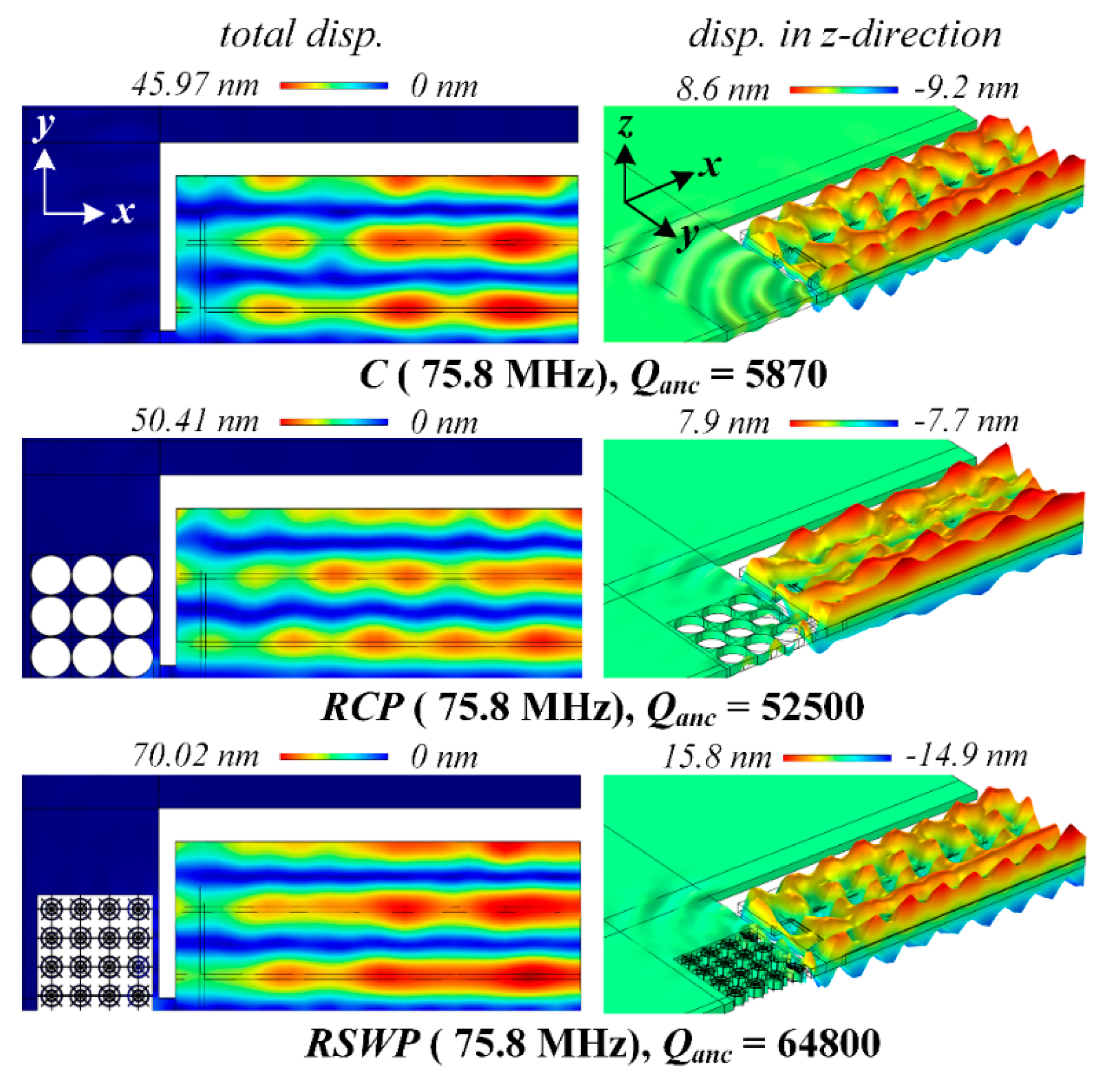
Figure 8 shows the displacement distributions of the resonant mode of resonator C, RCP, and RSWP. The design C shows the lowest
Qanc of 5870, indicating a large part of the acoustic wave dissipated through supporting tethers. The resonator RCP shows a relatively higher
Qanc of 52,500, and the device RSWP with the
SW-PnC array plate shows the most significant displacement isolation in undercut regions, as well as the anchoring substrate, with a
Qanc of up to 64,800. From the above discussion, the simulated
Qanc of resonators agrees well with the transmission properties of the delay line and solid line.
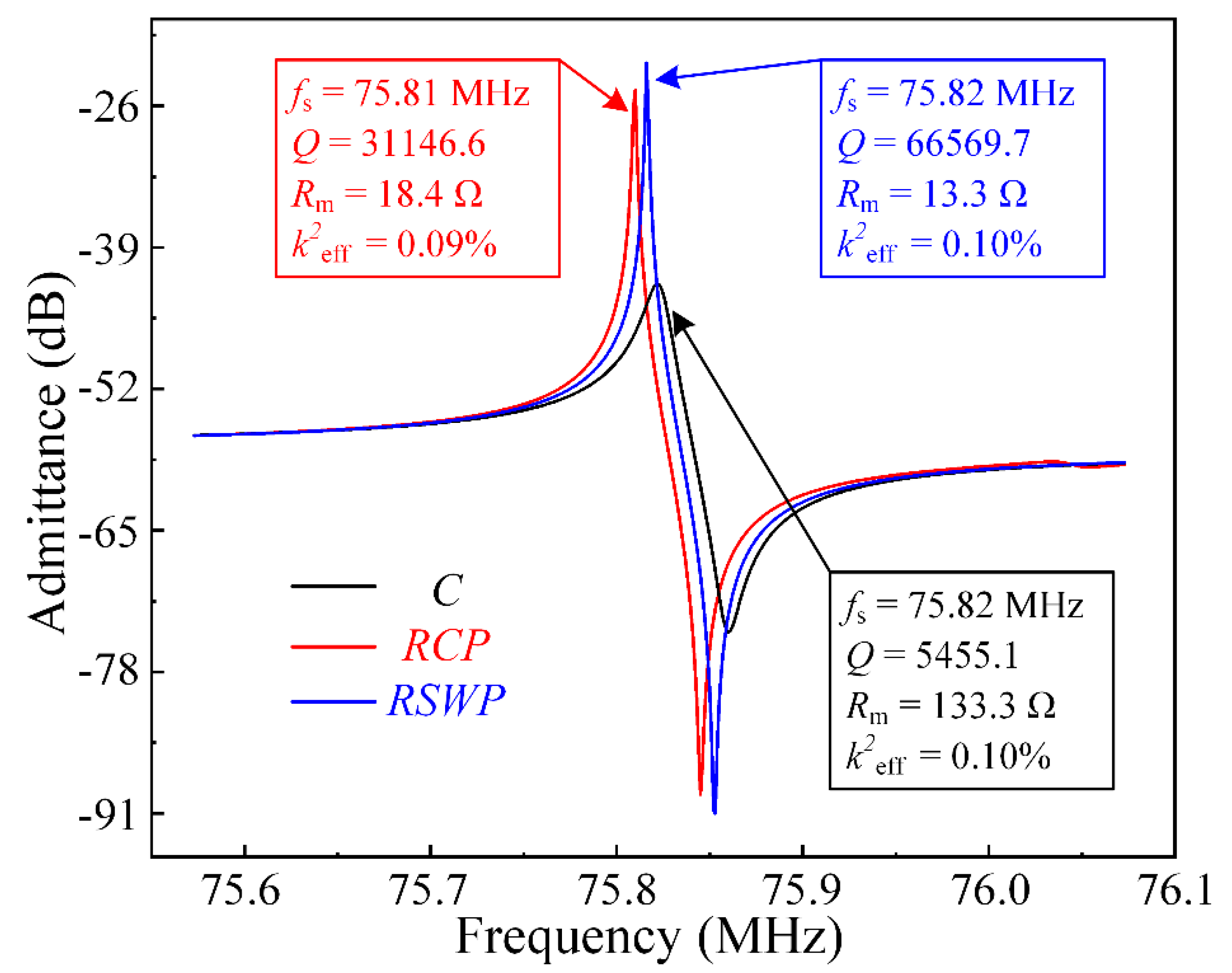
Furthermore, simulated admittance Y11 curves of resonators were calculated by the FEA frequency domain simulation under a 50-Ω load to extract the series resonant frequency (
fs), loaded
Q, motional resistance (
Rm), and the effective electromechanical coupling coefficient (
k2eff). The relationships among the
fs,
Q,
Rm, and
k2eff were defined as [
36,
37,
38]:
where ∆
f-3dB is the −3dB bandwidth around the series resonant frequency. The max {Re(Y11)} and
fp refer to the maximum value of the real part for the admittance Y11 and the parallel resonant frequency of resonators, respectively.
As shown in
Figure 9, the
Q of resonator RCP of 31,146.6 was 5.7 times larger than that of resonator C, which means most of the dissipated acoustic waves were reflected to the resonant body. It is worth noting that the
Q only considered the anchor loss (i.e., ignored thermo-elastic dissipation, viscous loss, etc.). Moreover, the
Q of the resonator RSWP with the
SW-PnC array plate was 66,569.7 at 75.82 MHz and showed an improvement of 12.2 times compared with that of C, while the motional resistance decreased to 13.3 Ω. In brief, the systematical investigation by the FEA simulation revealed that the application of
SW-PnC effectively reduced the anchor loss, and realized a satisfactory
Q.


