Article

A Novel Error Correction Method for Airborne HRWS SAR Based on Azimuth-Variant Attitude and Range-Variant Doppler Domain Pattern

1
National Key Laboratory of Microwave Imaging, Aerospace Information Research Institute, Chinese Academy of Sciences, Beijing 100190, China
2
School of Electronic, Electrical and Communication Engineering, University of Chinese Academy of Sciences, Beijing 100049, China
*
Author to whom correspondence should be addressed.
Remote Sens. 2025, 17(16), 2831; https://doi.org/10.3390/rs17162831
Submission received: 10 July 2025 / Revised: 9 August 2025 / Accepted: 13 August 2025 / Published: 14 August 2025

Abstract

In high-resolution and wide-swath (HRWS) synthetic aperture radar (SAR) imaging, the azimuth multi-channel technique effectively suppresses azimuth ambiguity, serving as a reliable approach for achieving wide-swath imaging. However, due to mechanical vibrations of the platform and airflow instabilities, airborne SAR may experience errors in attitude and flight path during operation. Furthermore, errors also exist in the antenna patterns, frequency stability, and phase noise among the azimuth multi-channels. The presence of these errors can cause azimuth multi-channel reconstruction failure, resulting in azimuth ambiguity and significantly degrading the quality of HRWS images. This article presents a novel error correction method for airborne HRWS SAR based on azimuth-variant attitude and range-variant Doppler domain pattern, which simultaneously considers the effects of various errors, including channel attitude errors and Doppler domain antenna pattern errors, on azimuth reconstruction. Attitude errors are the primary cause of azimuth-variant errors between channels. This article uses the vector method and attitude transformation matrix to calculate and compensate for the attitude errors of azimuth multi-channels, and employs the two-dimensional frequency-domain echo interferometry method to calculate the fixed delay errors and fixed phase errors. To better achieve channel error compensation, this scheme also considers the estimation and compensation of Doppler domain antenna pattern errors in wide-swath scenes. Finally, the effectiveness of the proposed scheme is confirmed through simulations and processing of airborne real data.

1. Introduction

High-resolution wide-swath (HRWS) imaging systems are an important trend in the future development of synthetic aperture radar (SAR) [1,2,3]. However, traditional single-channel SAR is constrained by the minimum antenna size, making it impossible to achieve high-resolution and wide-swath imaging simultaneously [4,5,6,7]. High resolution in the azimuth direction requires a large Doppler bandwidth, and the system’s pulse repetition frequency (PRF) must exceed the Doppler bandwidth to ensure image clarity without ambiguity. However, a higher PRF results in a reduction in the imaging swath [8,9]. To resolve this contradiction, the azimuth multi-channel SAR system has been proposed. It reduces the system’s PRF requirements through techniques such as displaced phase center antenna (DPCA) and non-uniform effective phase center (EPC) frequency spectrum reconstruction methods [10,11,12,13,14]. However, the aforementioned methods were proposed under the assumption of no practical errors. In reality, airborne azimuth multi-channel SAR systems are affected by various factors, such as aircraft vibrations, atmospheric turbulence, and system errors, which lead to suboptimal imaging results following azimuth multi-channel reconstruction and result in severe azimuth ambiguity [15,16,17,18,19,20].
To correct the azimuth multi-channel errors in practical systems, various error estimation methods have been proposed. Chen et al. proposed an internal calibration method that uses additional system data to acquire channel errors. However, this significantly increases the system complexity, making it less cost-effective in practical systems [21]. Feng et al. proposed the azimuth cross-correlation method, which can quickly and effectively estimate channel errors. Nevertheless, its performance is highly dependent on the estimation of the Doppler centroid [22]. In [23,24], methods were proposed that utilize the orthogonality between the noise subspace and the signal subspace to estimate channel errors under azimuth undersampling conditions. However, these methods require redundant channels, which complicate the practical implementation of SAR systems. In the image domain, Zhang et al. [25] proposed a channel error correction method based on weighted minimum entropy (WME), which estimates phase errors using coarsely focused images. However, similar to other image-domain methods, a finely focused image devoid of ambiguity requires further imaging processing, and the time cost of iterative imaging is relatively high [26,27,28,29].
Most of the aforementioned methods assume that channel errors are constant. However, in practice, both signal-domain and image-domain error estimation algorithms cannot avoid the impact of time-variant motion errors. Yang et al. proposed a two-step motion compensation (MoCo) method for single-channel SAR, which is a crucial step for achieving two-dimensional (2D) fine focusing in SAR imaging [30]. Building on this, Guo et al. proposed a multi-channel range-variant error estimation method based on antenna position compensation. Nonetheless, it does not consider azimuth multi-channel errors caused by aircraft attitude [31]. The algorithms proposed in [32,33] calibrate the amplitude and phase errors between channels, assuming that the residual phase errors can be corrected using the phase gradient autofocus (PGA) algorithm. However, the azimuth ambiguity caused by attitude errors cannot be suppressed. Researchers [23] proposed a novel matrix transformation method that requires only a single estimation and decomposition of the data covariance matrix, significantly reducing the computational burden. However, it does not consider azimuth-variant phase errors. Chen et al. proposed a quaternion-based attitude calculation method for 2D multi-channel systems, allowing multi-channel reconstruction and digital beamforming (DBF) imaging. However, this method does not consider the impact of range-variant antenna pattern errors in wide-swath [34].
The research in this article is implemented based on airborne azimuth multi-channel SAR. Compared with spaceborne HRWS SAR, the proposed scheme not only serves as a verification of key technologies and experimental validation but also can be directly applied to airborne HRWS SAR systems, such as early warning aircraft, for detecting targets on land and at sea [35,36,37,38,39]. To fully compensate for various channel errors caused by actual motion and system design, this article proposes a novel error correction method for airborne HRWS SAR based on azimuth-variant attitude and range-variant Doppler domain pattern. First, utilizing post-processed Inertial Measurement Unit (IMU) data and the attitude transformation matrix, the vector method is employed to estimate multi-channel attitude errors and the Doppler centroid variation with range-time changes. It should be noted that the attitude error mentioned in this article specifically refers to the phase error between channels caused by the occurrence of attitude angles due to the influence of actual factors, in contrast to the ideal uniform linear motion of the aircraft. Next, the azimuth Fourier transform (FT) is applied to the collected multi-channel raw echo to estimate the range-variant Doppler domain antenna pattern errors for each channel, corresponding to the attitude at each azimuth moment. Then, the 2D frequency-domain echo interferometry method is employed to estimate the fixed time delay and fixed amplitude-phase errors between channels. Finally, various error compensations are applied to the range-compressed undersampled multi-channel echo, followed by reconstruction. The reconstructed echo is then processed using the single-channel two-step MoCo method to obtain a finely focused 2D wide-swath SAR image. MoCo refers to compensating for the non-uniform and non-linear motion of SAR in the echo domain, enabling it to focus using existing imaging theory. The primary benefits of the proposed method are as follows:
(1)
This scheme considers the attitude errors between azimuth multi-channels in airborne SAR during actual flight operations. The vector method effectively estimates and compensates for these errors, thereby suppressing significant azimuth-variant phase errors between channels.
(2)
The impact of the Doppler domain antenna pattern of azimuth multi-channels on reconstruction is further considered, particularly when the Doppler centroid varies with attitude and range-time in wide-swath, and corresponding estimation and compensation methods are proposed.
(3)
After completing the 2D time-varying error compensation, the 2D frequency-domain echo interferometry method is employed to estimate fixed time delay and fixed phase errors, thereby eliminating the need for error estimation in the image domain and saving the time cost of separate imaging for each channel.
(4)
This scheme is applicable to the reconstruction and imaging of the inevitable small squint angles during actual flight, and has been validated using real flight data, demonstrating greater effectiveness.
The structure of this article is as follows: Section 2 introduces the ideal and actual multi-channel echo models and reconstruction method. Section 3 elaborates on various error estimation methods, including those for attitude errors, antenna pattern errors, and fixed delay and phase errors. Section 4 and Section 5 validate the effectiveness of this scheme through simulation and actual airborne multi-channel SAR echo. Section 6 summarizes the research content of this article.

2. Signal Model of Airborne Multichannel SAR

2.1. Ideal Signal Model and Reconstruction Method

As shown in Figure 1, the airborne SAR flies along the X-axis, which represents the azimuth direction, while the Y-axis, perpendicular to the X-axis, represents the range direction. The radar operates in a mode where one channel transmits signals and multiple channels receive them. The flight altitude is H , the number of azimuth channels is M , the receiving channel is indexed as m , and the spacing between adjacent channels is defined as d . d m = ( m ( M + 1 ) / 2 ) d represents the position of channel m relative to the reference channel, θ is the look angle, W s is the swath width, and the coordinate of the ground target point P is ( x 0 , y 0 , z 0 ) . Based on the principle of the EPC [40], the echo received by channel m can be expressed as
s m τ , η = A m w r τ 2 R m η c w a η + d m 2 V x 0 V exp j 4 π R m η λ e x p { j π K r ( τ 2 R m η c ) 2 }
where A m represents the complex constant related to the receiving channel m , τ represents the range time, η represents the azimuth time, w r represents the range window function, w a represents the azimuth window function, c represents the speed of light, V represents the radar flight speed, λ represents the wavelength, and K r represents the frequency modulation rate. R m η represents the slant range trajectory of the m -th receiving channel. According to the principle of EPC, it can be further expressed as follows:
R m η R r e f η d m 2 s i n δ
R r e f η = ( V η x 0 ) 2 + ( 0 y 0 ) 2 + ( H z 0 ) 2
where R r e f η represents the slant range from the reference channel to the ground target P , and δ represents the azimuth direction of arrival (DOA) of the echo.
According to Equation (2), the azimuth multi-channel steering vector can be expressed as
a = [ exp j 2 π d 1 λ s i n δ , exp j 2 π d 2 λ s i n δ , , exp j 2 π d M λ s i n δ ] T
where ( · ) T represents the vector transpose. Considering the relationship between the azimuth DOA and the Doppler frequency f η , s i n δ can be further expressed as
s i n δ = λ 2 V f η
The classic azimuth multi-channel reconstruction method proposed in [13] assumes that, under ideal conditions, the echoes between channels only have an azimuth delay relationship. According to Equations (4) and (5), the reconstruction filter for azimuth multi-channel can be expressed as
H 1 f η = e x p j π d 1 ( f η + 0 f P R F ) / V e x p j π d M ( f η + 0 f P R F ) / V e x p j π d 1 ( f η + M 1 f P R F ) / V e x p j π d M ( f η + M 1 f P R F ) / V 1
The f P R F represents the PRF. Following azimuth reconstruction, the equivalent PRF will be increased to M times PRF. When the equivalent PRF exceeds the Doppler bandwidth, the azimuth ambiguity in the SAR image is suppressed.

2.2. The Multi-Channel Signal Model Containing Errors

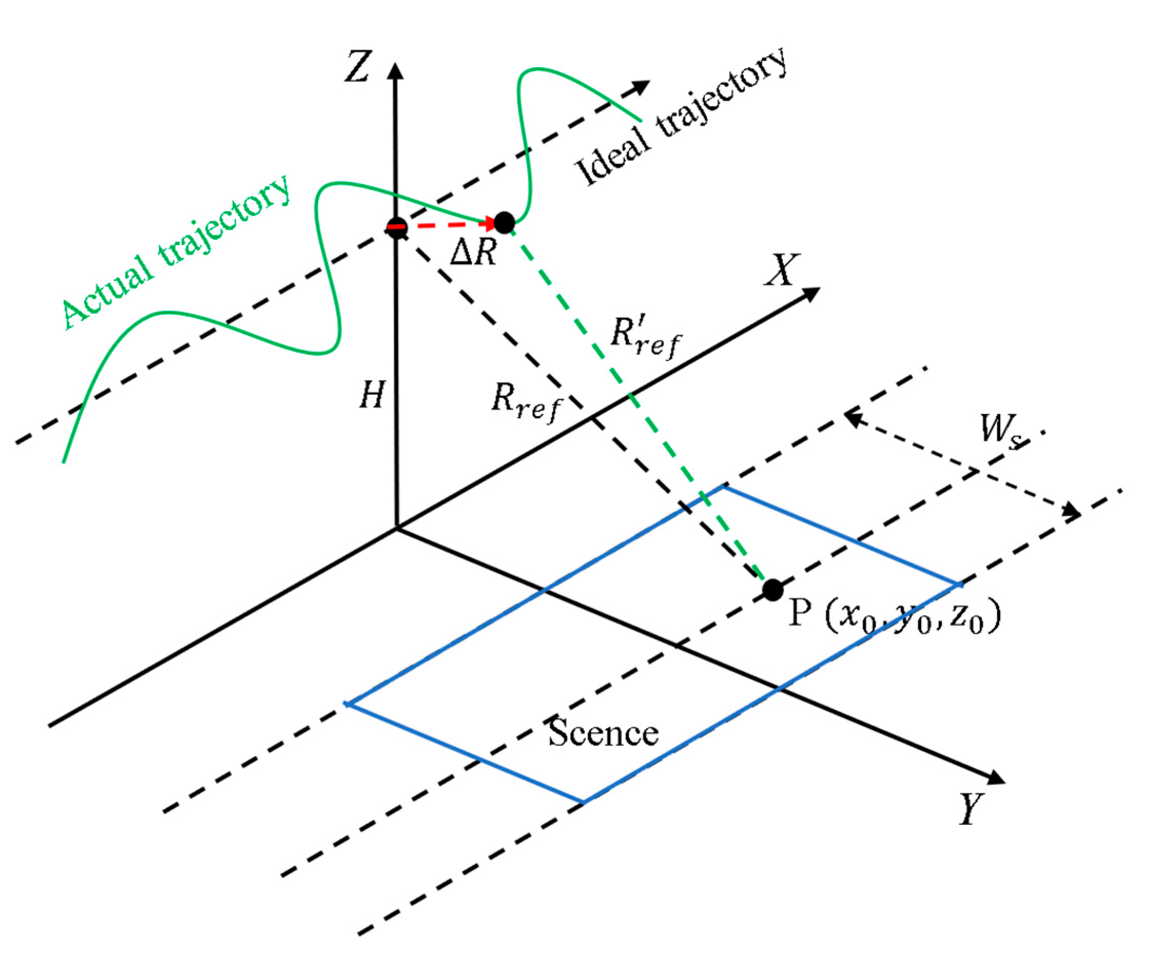
Due to the influence of atmospheric turbulence, aircraft vibrations, and other factors, the actual flight trajectory of the aircraft in Figure 2 is not an ideal straight line. It can be represented as ( V η + Δ x ( η ) ,   Δ y ( η ) ,   H + Δ z ( η ) ) , and the corresponding slant range in Equation (3) can be updated as
R r e f η = ( V η + Δ x ( η ) x 0 ) 2 + ( Δ y ( η ) y 0 ) 2 + ( H + Δ z ( η ) z 0 ) 2 = R r e f η + Δ R η
According to [24], the motion error R η for a single channel can be approximately expressed as
R η y η s i n θ + z η c o s θ .
In most cases, when the imaging swath is relatively small, the look angle θ can be approximated as constant within the swath width. In HRWS SAR, the imaging swath is larger, and the variation in the look angle with range time τ needs to be considered, which will be addressed during the calculation of attitude errors.
In practical systems, due to differences in antenna design and manufacturing, the antenna patterns of different channels cannot be completely identical, leading to amplitude and envelope errors. The azimuth antenna pattern of channel m can be further expressed as w a , m . In radio frequency (RF) circuits, due to inherent performance differences in components such as amplifiers and mixers, amplitude, and phase errors occur between channels, which can be represented as A m and φ m , respectively. During the sampling of echo, the start time of sampling differs between channels, resulting in a fixed range delay error between channels. During the flight of the aircraft, due to factors such as air currents and aircraft vibrations, various attitude changes inevitably occur with azimuth time. These attitude changes cause azimuth-variant phase errors between the echoes of different channels. In addition, according to Equation (8), the slant range error caused by the attitude is also related to the look angle θ . In wide-swath scenarios, it can be expressed as ψ m τ , η . Notably, attitude errors will cause slant range errors between channels, resulting in range delay errors. This range delay error, along with the previously mentioned fixed delay error, is represented as ε m η . Here, φ m , ε m η , and ψ m τ , η represent the errors of channel m relative to the reference channel.
Considering various errors in the practical multi-channel system, the echo after range compression, based on Equations (1) and (7), is given as
S m τ , η = A m w a , m η + d m 2 V x 0 V exp j 4 π R m η λ exp j 4 π R η λ   s i n c π B r τ 2 R m η c 2 R η c + ε m η exp j φ m exp j ψ m τ , η
where B r represents the signal bandwidth. The estimation and compensation methods for the aforementioned channel errors will be discussed below. In Section 4, the effectiveness of this method will be validated using simulation and real airborne SAR data.

3. Estimation and Compensation of Multiple Errors in the Echo Based on Attitude Information

3.1. Azimuth-Variant Attitude Error Estimation

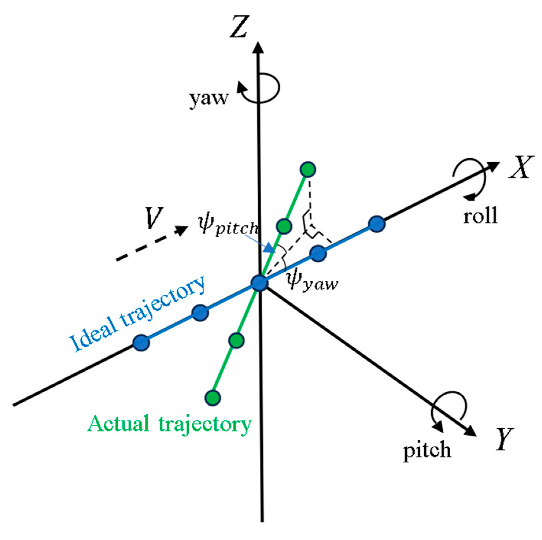
Due to airflow, vibrations, and other factors, the aircraft generates attitude angles during flight, including roll, pitch, and yaw angles, as shown in Figure 3. This causes the aircraft to rotate around the X, Y, and Z axes, respectively, leading not only to deviations in the flight trajectory but also to changes in the positional relationship between multiple channels. Thus, the echoes received by different channels are no longer in a simple azimuth time-delay relationship as described in Equation (4). The airborne IMU can record the aircraft’s attitude information in real-time during flight. The rotation sequence of the attitude angles follows the order of yaw, pitch, and roll. Therefore, the attitude rotation matrix can be expressed as
R o t ( η ) = 1 0 0 0 cos ψ r o l l ( η ) sin ψ r o l l ( η ) 0 sin ψ r o l l ( η ) cos ψ r o l l ( η ) cos ψ p i t c h ( η ) 0 sin ψ p i t c h ( η ) 0 1 0 sin ψ p i t c h ( η ) 0 cos ψ p i t c h ( η ) c o s ( ψ y a w ( η ) ) s i n ( ψ y a w ( η ) ) 0 s i n ( ψ y a w ( η ) ) c o s ( ψ y a w ( η ) ) 0 0 0 1
where ψ r o l l ( η ) represents the roll angle of the aircraft at azimuth time η , ψ p i t c h ( η ) represents the pitch angle, and ψ y a w ( η ) represents the yaw angle.
Specifically, the presence of ψ y a w ( η ) will cause a change in the starting time at which each channel receives the echo, leading to range delay errors. Furthermore, it will alter the spacing between the channels in the azimuth direction, affecting the azimuth reconstruction performance. The presence of ψ p i t c h ( η ) will cause positional errors along the altitude direction between channels, which will manifest as phase errors between the channels due to attitude. Although ψ r o l l ( η ) itself has little direct impact on the azimuth multi-channel attitude, it is coupled with the other two angles and consequently affects the phase errors between the channels.
Based on the post-processed IMU data, the aircraft’s three-dimensional (3D) velocity vector can be expressed as
v η = V X η , V Y η , V Z η
where V X η , V Y η , and V Z η represent the 3D components of V along the X-, Y-, and Z- directions, respectively. Under ideal conditions, the antenna axis vector of the azimuth channel m is expressed as
P m η = d m 2 , 0,0 T
In the actual trajectory, the azimuth multi-channel antenna axis vector is affected by the attitude angles. According to Equation (10), it can be expressed as
P m η = R o t η P m η
Due to the non-uniform straight-line motion of the aircraft, the velocity vector for channel m should be expressed as
v m ( η ) = d m 2 v ( η ) v ( η )
where · represents the norm of the vector. Due to the impact of the attitude, there is a difference between P m ( η ) and v m ( η ) , and therefore the compensating attitude error can be expressed as
Δ P m η = P m η T v m η
While the attitude error differs from the slant range error of a single channel, it has been transformed into the slant range error between channels through Equations (13) and (15). Based on Equations (8) and (9), it can be further expressed as
ψ m τ , η =   4 π λ P m , Y ( η )   s i n θ τ + P m , Z ( η ) c o s θ τ
where P m , Y ( η ) represents the Y-axis component of the attitude error vector Δ P m ( η ) , and P m , Z ( η ) represents the Z-axis component of the attitude error vector Δ P m ( η ) . Substituting Equation (16) into the corresponding terms of Equation (9) allows for the compensation of the azimuth-variant attitude errors between channels.

3.2. Range-Variant Pattern Error Estimation

In Equation (9), the differences in w a , m between different channels mainly depend on the variations in the antenna radiation pattern. Since the variation in the look angle for wide-swath scenarios needs to be considered, Figure 4 provides an estimation of the antenna pattern error in the Doppler domain based on real airborne multi-channel SAR data, illustrating the specific manifestation of the pattern error. From Figure 4, it can be observed that the differences in the antenna patterns primarily pertain to amplitude and beamwidth. Therefore, the time-domain antenna pattern of channel m can be approximately expressed as
G m δ , τ = β m s i n c 2 α m δ w ( δ δ s τ )
where β m represents the amplitude coefficient of the antenna pattern, δ w denotes the azimuth beamwidth, α m represents the azimuth beamwidth coefficient, and δ s τ denotes the azimuth squint angle at range time τ .
When the imaging swath is relatively large, the variation in the look angle across different ranges in the scene becomes significant. As a result, the echoes from different ranges will have different squint angles δ s τ , requiring the antenna pattern compensation to be adjusted accordingly with the range time τ . According to Equation (5), the Doppler centroid f d ( τ ) can be used to represent the corresponding squint angle δ s τ . The estimation of antenna pattern errors for each channel can be directly performed in the Doppler domain of the received echoes.
In airborne SAR signal processing, it can be approximately assumed that the Doppler centroid is constant over a segment of azimuth time. Therefore, P m , ψ y a w and ψ p i t c h can respectively represent the result of averaging P m ( η ) , ψ y a w ( η ) and ψ p i t c h ( η ) . If the coupling relationship among the three attitude angles is not considered, the calculation of the squint angle can be expressed as
δ s τ = a t a n ( cos θ τ cos ψ y a w tan ψ p i t c h + s g n s i n ( θ τ ) t a n ( ψ y a w ) )
where the value of s g n is ± 1 , which depends on the side-looking direction of the radar. However, in reality, the three attitude angles do not have a completely independent relationship. Such a calculation result will lead to errors and affect the performance of signal reconstruction. This article proposes using a vector method to calculate the Doppler centroid variation with range time. Besides the vectors associated with Equations (13) and (14), it is necessary to define an additional antenna line-of-sight vector, as follows:
ρ τ = ρ x τ , ρ y τ , ρ z τ
Since the system uses azimuth multiple channels, the antenna line-of-sight vector ρ τ should be perpendicular to the antenna axis vector P m , i.e., ρ τ · P m = 0 . According to the definition of vector dot product, ρ τ can be expressed as
ρ τ · P m = P m , X ρ x τ + P m , Y ρ y τ + P m , Z ρ z τ = 0
where · represents the vector dot product, and P m , X , P m , Y , and P m , Z denote the X, Y, and Z components of the vector P m , respectively.
The Doppler centroid of the echo depends on the azimuth squint angle, which can be regarded as the angle between the antenna line-of-sight vector ρ τ and the velocity vector v m , where m can be the index of any channel. According to Equation (5), the calculation for the Doppler centroid can be expressed as
f d τ = 2 V λ cos π 2 δ s τ = 2 V λ ρ τ · v m ρ τ v m
where v m represents the average value of v m ( η ) throughout azimuth time. According to Equation (17), the compensation of antenna pattern error requires different compensation operations to be performed along each range gate in the range-Doppler domain. It should be noted that under complex flight conditions, the range-variant pattern error does not only depend on the difference in look angles but also on the aircraft’s attitude changes. The range-variant pattern error can be calculated and compensated by using Equation (21) proposed in this article.

3.3. Estimation of Fixed Time Delay and Phase Error

As a new correction method for 2D time-variant errors has been proposed in this article, the remaining fixed phase and delay errors can be addressed using the existing interferometry method in the field of signal processing. According to the properties of FT, a time delay in the time domain can be equivalently represented as a linear phase in the frequency domain. According to Equation (9), after the aforementioned error compensations are completed, the echo of channel m , which contains fixed phase and delay errors, can be expressed as
S ^ m f τ , f η = S ^ r e f f τ , f η e x p ( j 2 π f η ϵ m ) e x p ( j 2 π f τ ε m ) exp j φ m
where S ^ r e f ( τ , η ) and S ^ m ( τ , η ) represent the echoes of the reference channel and channel m after the aforementioned error compensation, and S ^ r e f f τ , f η is the frequency-domain echo obtained after the 2D FT of S ^ r e f ( τ , η ) , where f τ represents the range frequency domain, and f η represents the Doppler domain. ϵ m represents the azimuth delay, which depends on the azimuth channel spacing d . Following attitude error compensation, the azimuth-variant part of ε m η has been compensated. Here, only the fixed delay error is estimated, and it is represented as ε m .
According to Equation (22), the difference between S ^ m ( f τ , f η ) and S ^ r e f f τ , f η is only two one-dimensional linear phases and a fixed phase. By performing a conjugate multiplication between the two, the phase required for Equation (22) can be extracted. Therefore, it can be expressed as
D = F S ( F f τ , f η ( F S ( S ^ r e f f τ , f η )     c o n j ( F S ( S ^ m f τ , f η ) ) ) )
where F S represents 2D fftshift, F f τ , f η represents the 2D FT, c o n j · denotes the complex conjugate, and represents the Hadamard product.
Based on the properties of FT, the presence of a linear phase in the time domain causes a shift in the signal in the frequency domain. According to Equation (23), the method for estimating the range delay error after interference can be expressed as
ε m = a n u m 2 + 1 a m a x 2 f s
where a n u m represents the number of rows of matrix D , f s represents the sampling frequency, and ( a m a x , b m a x ) represents the 2D index of the position of the maximum amplitude in the complex matrix D .
After compensating for the fixed delay error, according to Equations (22) and (23), the result of the conjugate multiplication leaves only a fixed phase. Therefore, its corresponding 2D frequency domain is a delta function, and the phase of this delta function represents the fixed phase error of channel m relative to the reference channel. The estimation of this error can be expressed as
φ m = a r g D ( a m a x , b m a x )
where a r g · represents the phase extraction of a complex number. Substituting Equations (24) and (25) into the corresponding terms in Equation (9) enables the compensation of the fixed delay error and fixed phase error. The estimation and compensation of amplitude errors are relatively straightforward. The amplitude has already been compensated for during the aforementioned antenna pattern error compensation process.
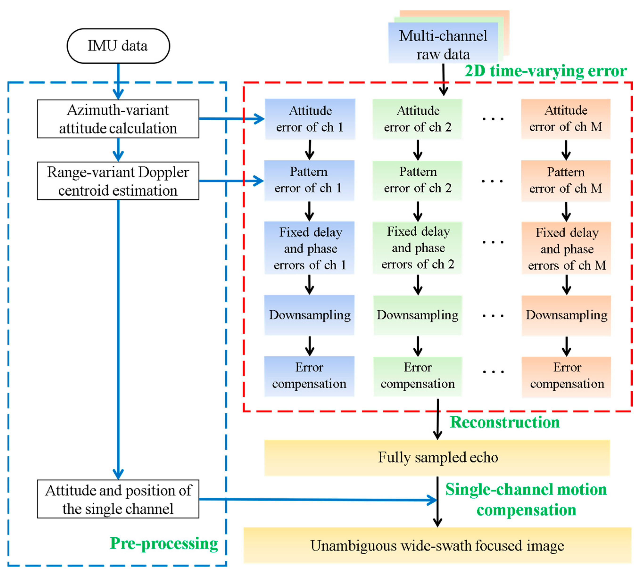
Figure 5 illustrates the fundamental process of a novel error correction method for airborne HRWS SAR based on azimuth-variant attitude and range-variant Doppler domain pattern. The detailed steps are described as follows:
First, based on the post-processed airborne IMU data, the aircraft’s motion attitude varying with azimuth time is obtained, and Equation (16) is used to estimate the multi-channel attitude error.
Second, based on the attitude calculation from the previous step, the vector method in Equation (21) is used to compute the Doppler centroid varying with the range time. This further enables the estimation and compensation of the Doppler antenna pattern error for multi-channel echo.
Third, a 2D frequency-domain echo interferometry method is adopted, as described in Equation (23), to obtain the estimation results for fixed range delay and fixed phase errors.
Fourth, to verify the accuracy of the error estimation, azimuth downsampling on the echo is performed to ensure that the downsampled PRF is smaller than the Doppler bandwidth. The accuracy of the error estimation is evaluated by the azimuth ambiguity energy in the reconstructed image.
Fifth, range compression is performed on the downsampled echo, and various errors are compensated as described in Equation (9).
Sixth, perform multi-channel azimuth reconstruction in squint mode to obtain the fully sampled echo, with an equivalent PRF being M times the downsampled PRF.
Finally, based on the single-channel attitude and position information obtained from the airborne IMU, perform the single-channel two-step MoCo on the reconstructed echo to complete the 2D focusing.

4. Simulation and Real Data Results

4.1. Point Target Simulation

To validate the proposed method for 2D time-varying error calibration for airborne azimuth multichannel SAR imaging, experiments were performed using simulated point target data and real multi-channel HRWS SAR data. Table 1 presents the parameters for the simulation experiments. Three azimuth channels are used. The downsampled PRF is 100 Hz, which is smaller than the Doppler bandwidth of 250 Hz, resulting in azimuth ambiguity.
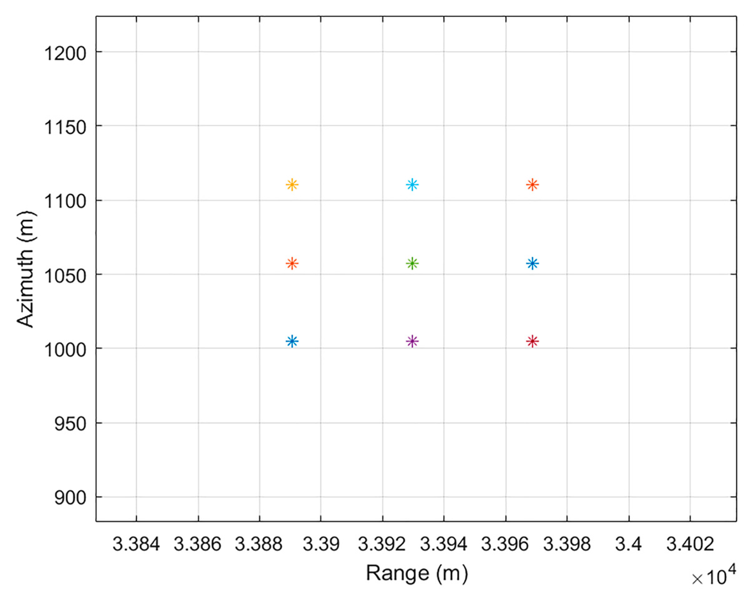
To align with real multi-channel data, this article simulates a flight trajectory with time-varying attitude angles and incorporates range delay, fixed phase, and antenna pattern errors into the echo [34]. The point target position distribution is shown in Figure 6. The fixed phase errors added to the three channels are 0°, 50°, and −80°, respectively.
The simulated three-channel time-domain antenna pattern is expressed as
G 1 δ = s i n c 2 ( 0.886 / δ w δ )
G 2 δ = s i n c 2 ( 1.1 / δ w δ )
G 3 δ = s i n c 2 ( 0.6 / δ w δ ) .
The simulated attitude angles are expressed as
ψ y a w ( η ) = ( 1 + 0.2 c o s ( 2 π η T η ) )
ψ p i t c h ( η ) = ( 0.5 + 0.2 c o s ( 2 π η T η ) )
ψ r o l l ( η ) = ( 2 + 0.2 c o s ( 2 π η T η ) )
where T η represents the synthetic aperture time, and the unit of the attitude angles is degree.
For the echo simulated from the point targets in Figure 6, the error estimation and compensation are performed using the method described in Figure 5. The estimated phase error results are shown in Table 2. After compensating for the time delay error and pattern error, the phase error results directly estimated from echo include the attitude error and the fixed phase error. The error results are represented by the mean value. Through the calculation of the attitude error, it can be found that the attitude error phase of the 3rd channel is twice that of the 2nd channel, which is consistent with the actual influence of the attitude on the phases of different channels. After compensating for the azimuth-variant attitude error, the estimated fixed error results match the simulated parameters, with a deviation of approximately 0.01 rad, which verifies the effectiveness of the attitude error and fixed phase error estimation methods proposed in this article.
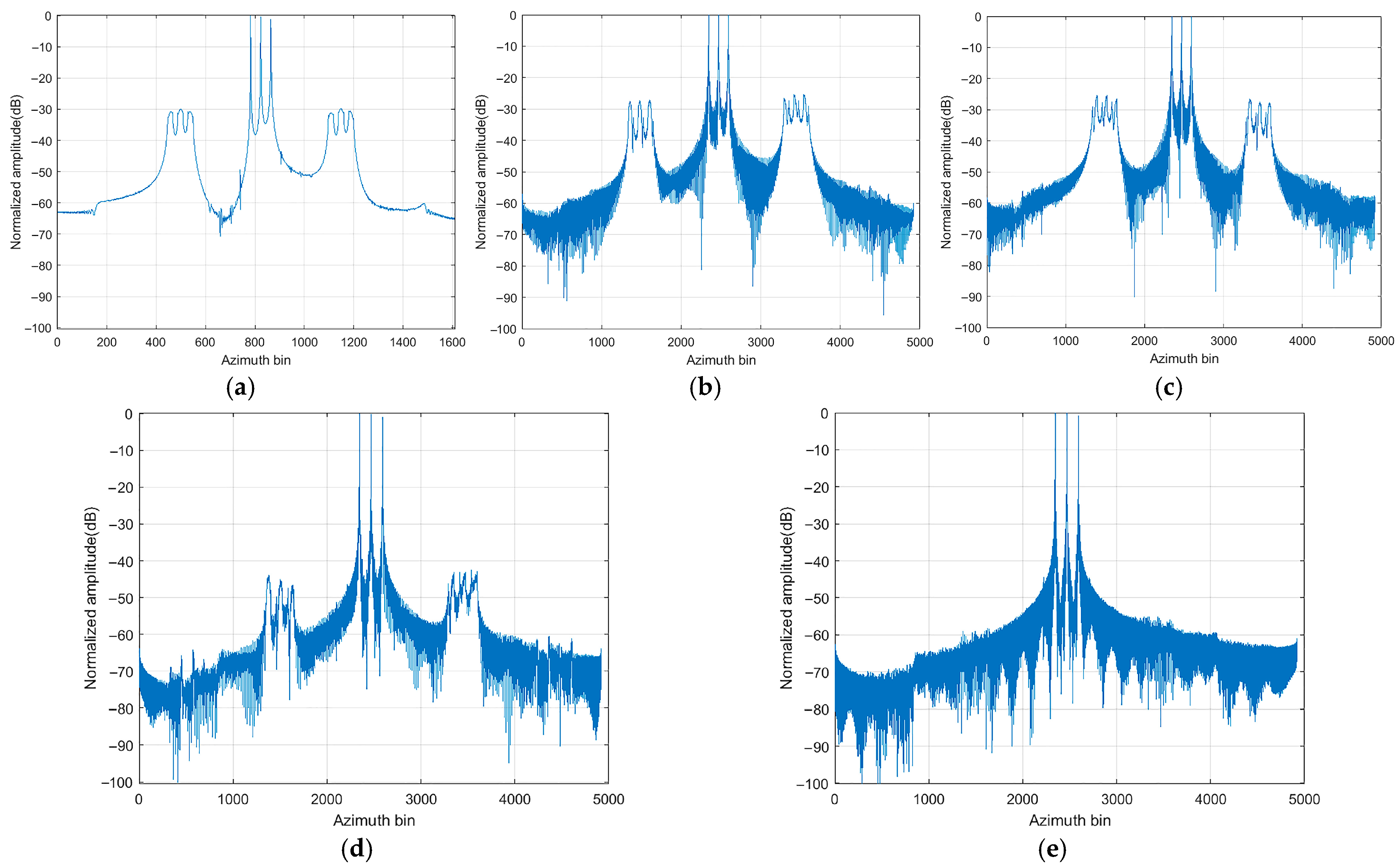
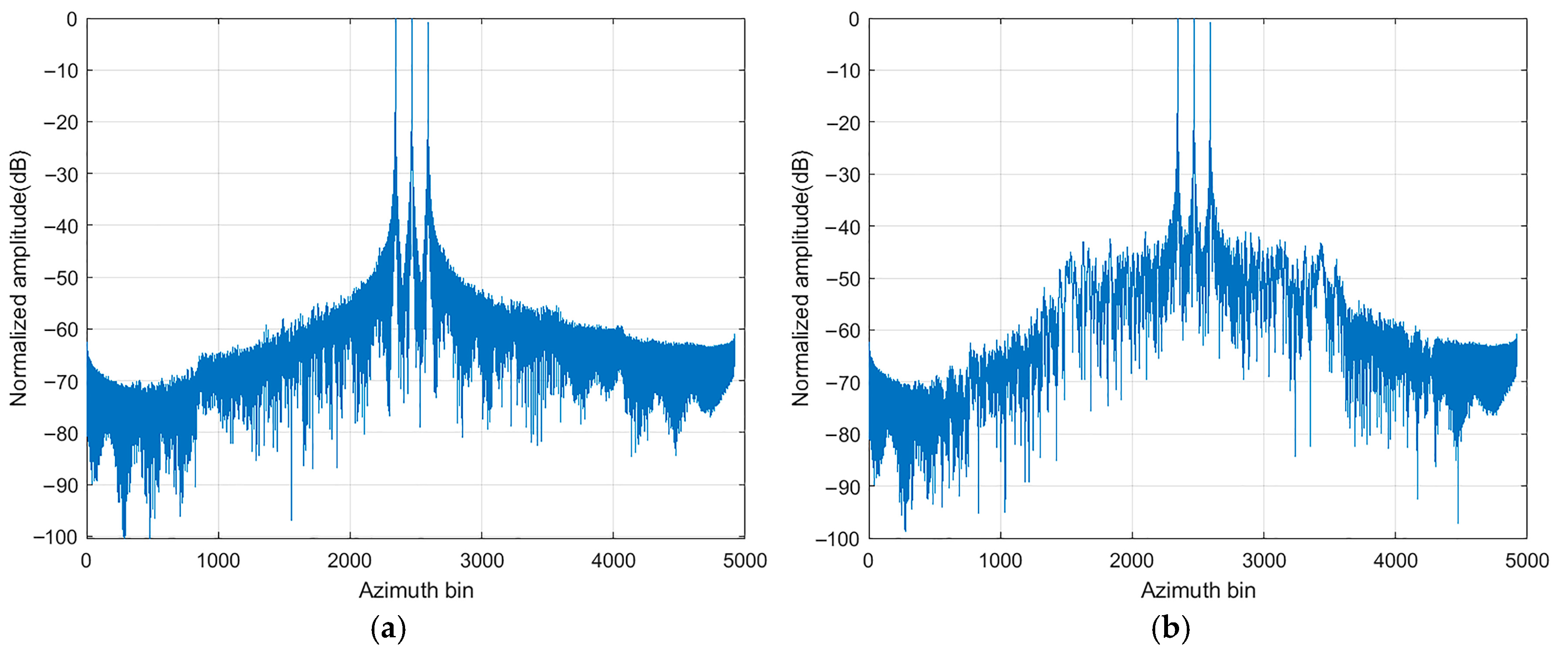
Following the error estimation, the reconstructed imaging result is presented in Figure 7. It can be observed that the imaging result of the single-channel undersampled echo after MoCo contains strong azimuth ambiguity energy, as shown in Figure 7a. After directly performing azimuth reconstruction on the multi-channel undersampled echo, azimuth ambiguity persists, and its energy remains unchanged, as shown in Figure 7b. Following the estimation of fixed phase and time delay errors, the result obtained by using the traditional single-channel MoCo scheme [30] is shown in Figure 7d, showing a residual azimuth ambiguity of −45 dB. After applying the proposed method to compensate for all the mentioned errors, the result is shown in Figure 7e. The azimuth ambiguity disappears, and the ambiguous energy is suppressed by approximately 30 dB.
To further illustrate the impact of various errors on multi-channel reconstruction, Figure 7c presents the imaging results based on the proposed scheme in this article but without fixed phase error compensation. Compared with Figure 7e, it can reflect the influence of the fixed phase error on the reconstruction. Due to the periodicity of the phase error within 2π, the separate compensation of any single phase error does not necessarily lead to an improvement in the ambiguous energy. The specific quantitative analysis corresponding to Figure 7 is shown in Table 3, which presents the azimuth indicators of the point target after imaging, such as peak side lobe ratio (PSLR), impulse response width (IRW), and ambiguity energy ratio.
It can be seen that the method proposed in this article effectively compensates for various types of errors, resulting in well-focused images without ambiguity. Various types of errors not only affect the azimuth ambiguity energy after reconstruction but also have a significant impact on image indicators. For example, they increase the PSLR and IRW, affecting the focusing level of the target. By comparing the ambiguity energy before and after compensation, the attitude error and pattern error compensation algorithm proposed in this article has a significant effect compared with the traditional scheme, achieving an ambiguity energy suppression of 14 dB.

4.2. Real Airborne SAR Data

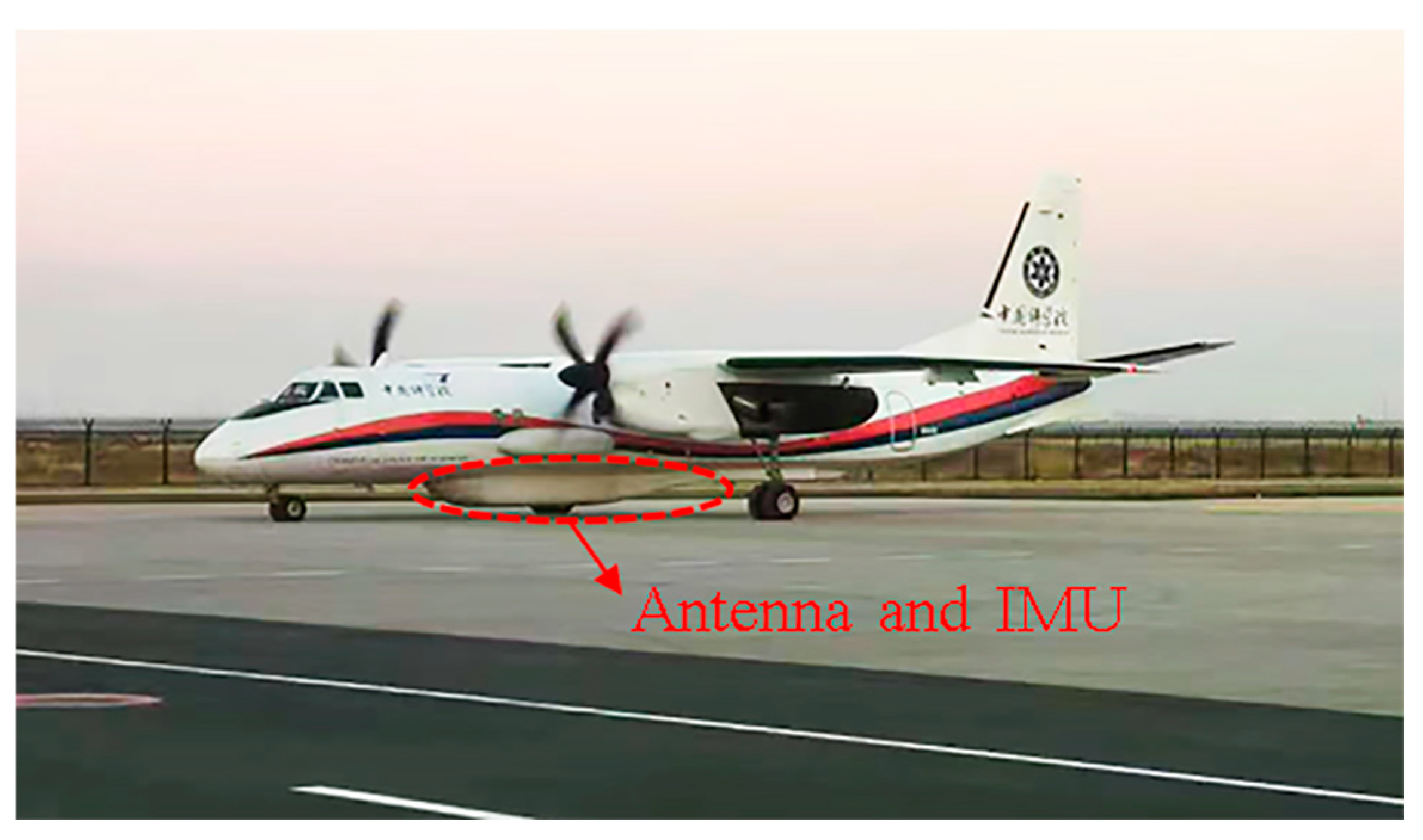
This subsection presents the use of SAR three-channel raw data to evaluate the effectiveness of the proposed method, with the system parameters listed in Table 4. The measured data were collected in 2024 by the airborne HRWS SAR system developed by the Aerospace Information Research Institute of the Chinese Academy of Sciences. The raw data includes echoes from three azimuth channels, and the IMU used is the POS 610, with an accuracy of 0.05 m. The aircraft used is shown in Figure 8.
Since the total imaging swath width in the actual scene is on the order of dozens of kilometers, the pattern error that varies with the Doppler centroid within the scene, calculated according to Equation (21), is shown in Figure 9. It can be seen that the Doppler centroids at the near end and the far end of the scene differ by approximately 80 Hz. The pattern error among multiple channels is not fixed but continuously changes along the range time and aircraft’s attitude, and separate compensation should be carried out at different range sampling points.
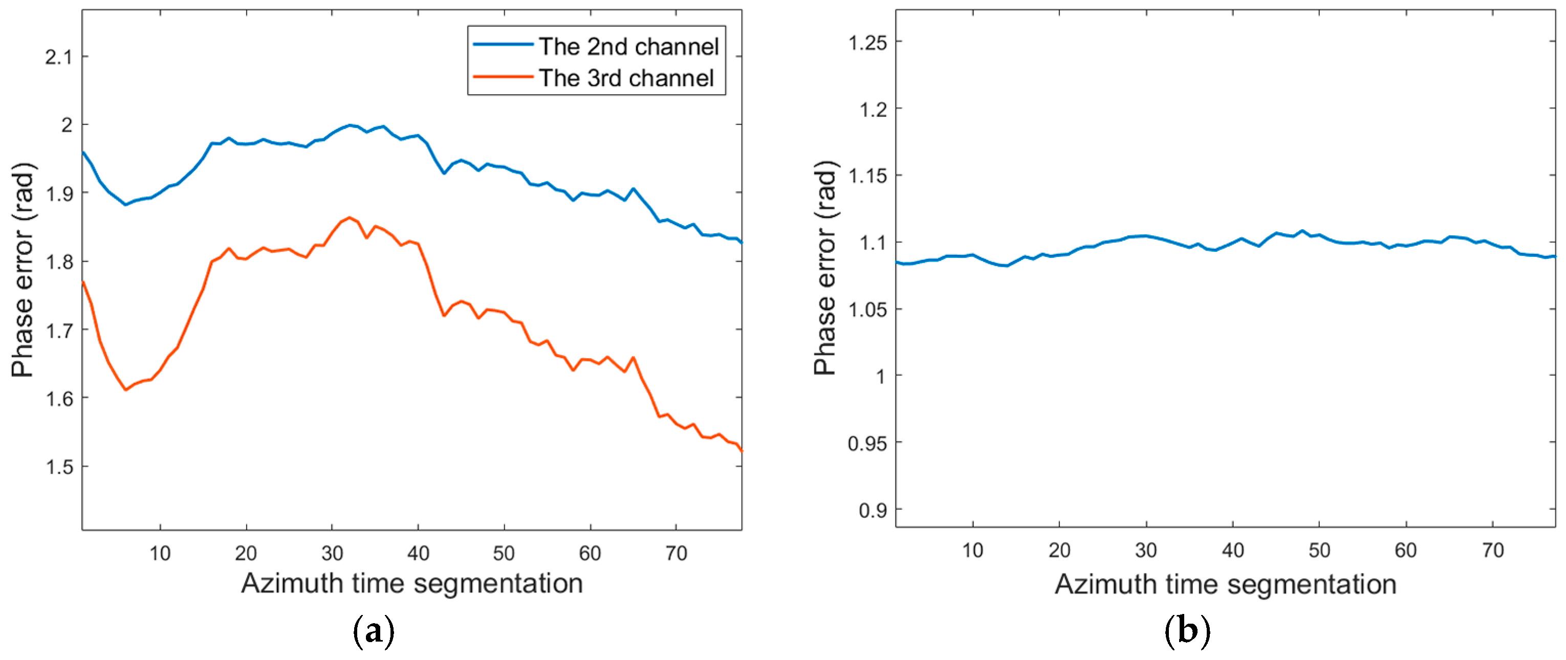
In order to clearly describe the fixed phase error and the azimuth-variant attitude error, after compensating for the pattern error and the fixed time delay error, Figure 10a presents the error estimation result according to Equation (23). It can be seen that there are significant phase errors between channels, which vary continuously with azimuth time, with fluctuations reaching around 0.3 rad. In addition, it is worth noting that since the 1st channel is selected as the reference channel in the measured data, the interval between the 3rd channel and the 1st channel is twice that between the 2nd channel and the 1st channel. Therefore, the impact of attitude errors on the 3rd channel will be twice as large as on the 2nd channel. Figure 10a illustrates that the errors of the 2nd and 3rd channels vary in the same way with azimuth time, and the amplitude of variation in the 3rd channel is approximately twice that of the 2nd channel. This further verifies the correctness of Equation (16), which is proposed in this article.
As shown in Figure 10b,c, based on the results in Figure 10a, the results after attitude error compensation are presented. The residual errors occur primarily due to the fixed phase error. Figure 10d shows the error estimation results after all error compensations using Equation (23). The residual errors are nearly zero, with fluctuations along the azimuth time of less than 0.05 rad. The residual error fluctuations for the 2nd channel are less than 0.02 rad, and the phase errors between channels have been almost eliminated.
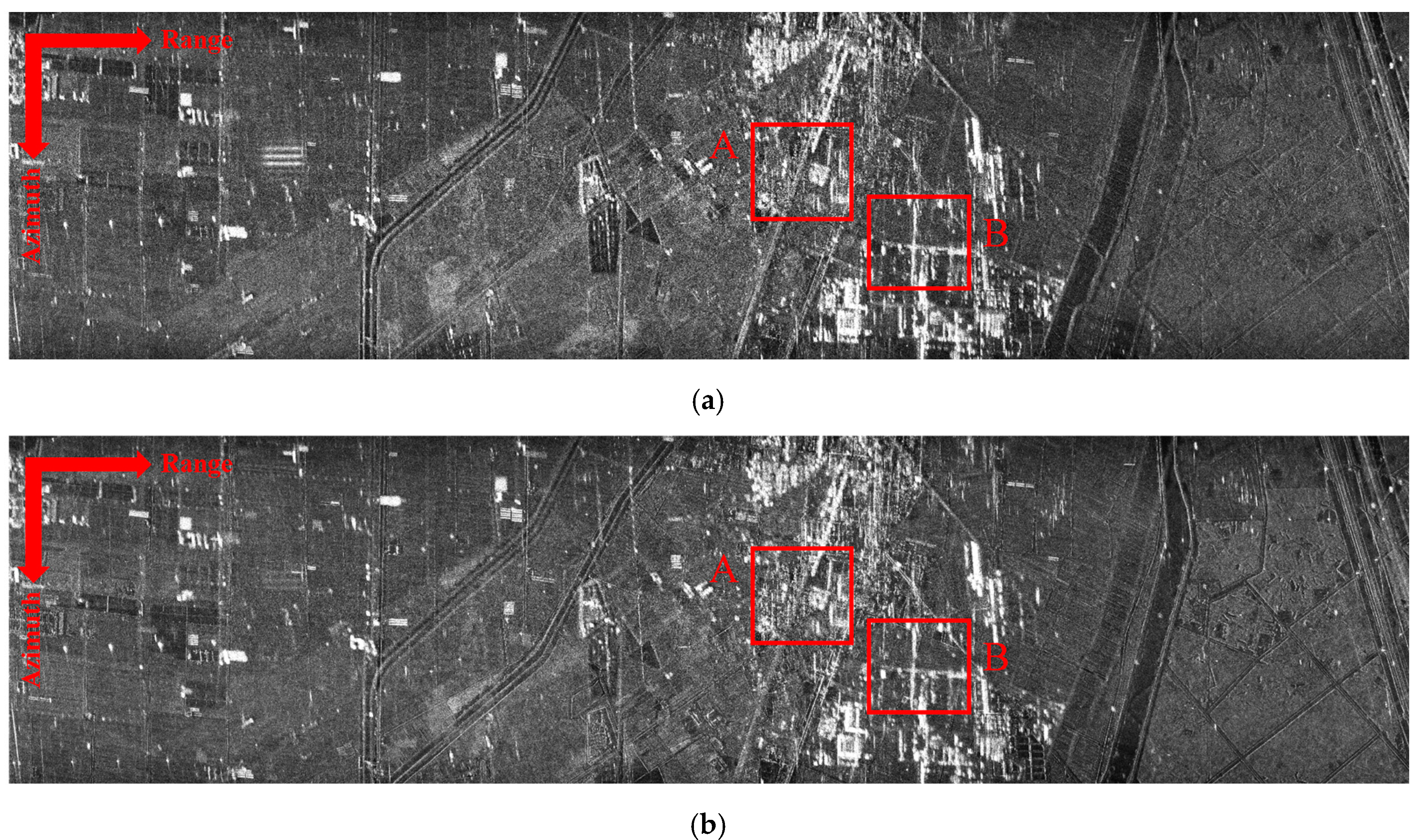
As shown in Figure 11, a comparison of the reconstruction results for the measured airborne SAR azimuth three-channel data is presented. Figure 11a represents the imaging result of the undersampled data, where significant azimuth ambiguity is observed, making the image difficult to interpret. Figure 11b builds upon this by performing azimuth multi-channel reconstruction without compensating for any errors. It can be observed that the azimuth ambiguity remains strong, with no significant improvement in intensity. Figure 11c presents the reconstruction results of the scheme in this article when only the fixed phase error is not compensated. Figure 11d shows the reconstruction result after the error compensation of the traditional scheme [30]. Through comparison, it can be seen that the attitude error, fixed phase error and pattern error have a significant impact on the reconstruction. Figure 11e presents the compensation and reconstruction result using the proposed method, which indicates that azimuth ambiguity is almost completely suppressed, resulting in a more remarkable 2D image compared to the traditional scheme.
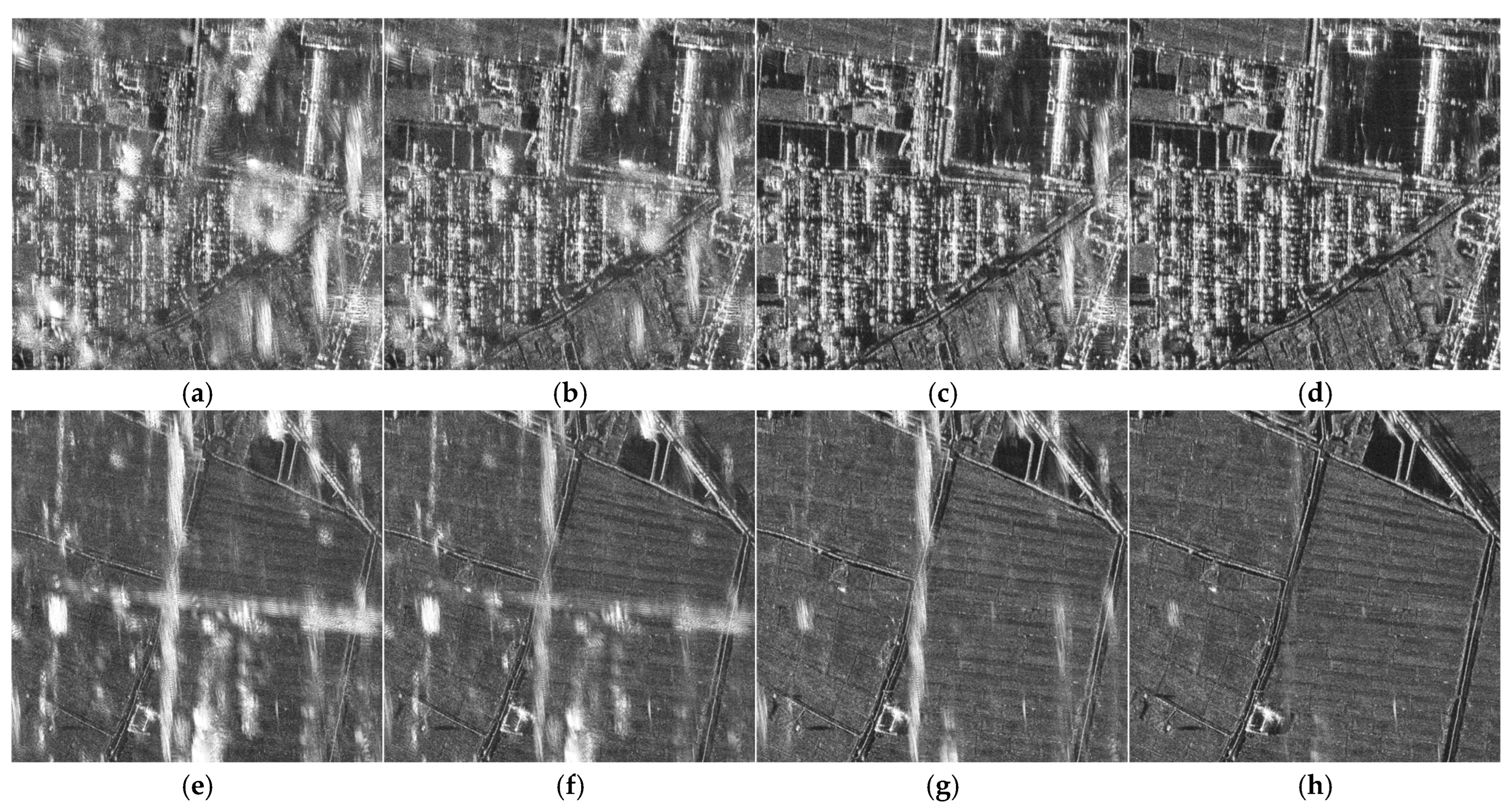
In order to more clearly illustrate the influence of various errors considered in the proposed scheme of this article on the reconstruction performance, Figure 12a–d present the local images of region A in Figure 11b–e and Figure 12e–h present the local images of region B. In this way, the ability of the proposed scheme in this article to suppress azimuth ambiguity can be seen more clearly. Since the number of azimuth pulses of the undersampled data in Figure 11a is different, it is not reflected in Figure 12. As the actual multi-channel system often calibrates the fixed delay error in advance, most of the range delay errors in the echo are caused by attitude errors. The separate compensation of the fixed delay error has little impact on the suppression of azimuth ambiguity. Therefore, from the comparison between Figure 12b,d, it can be seen that the fixed phase error has a considerable impact on signal reconstruction, and it is absolutely necessary to carry out effective compensation. Compared with the traditional scheme shown in Figure 12c, the scheme proposed in this article, as illustrated in Figure 12d, incorporates compensation for both azimuth-variant attitude error and range-variant pattern error, resulting in a more effective suppression of azimuth ambiguity than the traditional scheme. This demonstrates that the error estimation of the proposed scheme in this article is more accurate.
In order to quantitatively analyze the image quality of the imaging results of different schemes, image entropy is adopted as a measurement indicator. Image entropy reflects the uncertainty of information contained within an image. When the gray level distribution of the image is more concentrated and there are fewer changes, the image entropy is smaller. The calculation can be expressed as
E = l = 1 L k = 1 K Ι ( l , k ) log 2 Ι ( l , k )
where Ι ( l , k ) represents the ratio of the amplitude of the pixel at the l -th row and k -th column to the total amplitude of the image. The analysis of the image entropy for region A in Figure 12 is presented in Table 5. Compared to the result without error compensation, the image entropies of both the traditional scheme and the scheme proposed in this article are lower. Moreover, the image entropy of the scheme proposed in this article is the lowest, indicating that the gray level distribution in its image is more concentrated and the ambiguity energy is the least.
An azimuth profile is created for the noise background, which contains a point target in region A. The energy comparison between the scheme proposed in this article and the traditional scheme is shown in Figure 13. The boxed region represents the noise background region, and its energy is significantly lower compared to that of the point target. The average energy of the noise region for the scheme proposed in this article is −35.80 dB, whereas for the traditional scheme, since 2D time-varying error compensation is not considered, the average energy of the noise region reaches −27.36 dB. Therefore, through the analysis of real data, the feasibility and effectiveness of the proposed azimuth multi-channel error estimation and compensation scheme are validated.

5. Discussion

The azimuth-variant attitude error compensation component of the proposed scheme in this article relies on IMU data. Therefore, it is necessary to discuss the accuracy of the IMU to clarify the applicable scope of the proposed scheme. Currently, the POS 510 and 610, which are widely used in airborne SAR systems, can achieve absolute accuracies in attitude angle measurement within 0.008° and 0.005°, respectively.
Accordingly, random errors with a mean of 0 and standard deviations of 0.01° and 0.1° were introduced into Equations (29)–(31), and the imaging results of the proposed scheme are presented in Figure 14. It can be observed that Figure 14a is essentially identical to Figure 7e, indicating that the proposed scheme can fully accommodate measurement errors of approximately 0.01°. For Figure 14b, where the measurement error reaches 0.1°, the ambiguity energy in the imaging result increases but remains below −40 dB, which is acceptable. Thus, the IMU accuracy requirements of the proposed scheme can be met by most IMUs, and optimal performance can be achieved with the POS 510 and 610.

6. Conclusions

This paper presents a novel error correction method for airborne HRWS SAR based on azimuth-variant attitude and range-variant Doppler domain pattern, which comprehensively addresses various errors encountered in actual airborne SAR multi-channel data, including attitude, Doppler pattern, time delay, and fixed amplitude-phase errors. Compared to traditional error estimation methods, this scheme utilizes the vector method and attitude rotation matrix to estimate and compensate for azimuth-variant phase errors resulting from changes in aircraft attitude. On this basis, it further considers the influence of antenna pattern variations with attitude and range gate on azimuth reconstruction in wide-swath scenes. Finally, a 2D frequency domain echo interference method is used to estimate fixed delay and phase errors. Compared to traditional methods, this scheme provides a detailed analysis of the sources and impacts of channel attitude errors and antenna pattern errors, offering effective estimation methods to address azimuth-variant and range-variant phase errors. It avoids the time cost of error estimation in the image domain, achieves multi-channel error compensation in wide-swath scenes, and also demonstrates excellent performance in small-squint-angle imaging. The effectiveness of the proposed scheme is validated through airborne HRWS SAR simulations and real data. The performance of the proposed scheme in this article relies on accurate IMU data. Future research can build upon this foundation to develop a multi-channel error correction scheme that does not depend on IMU or can leverage low-precision IMU data for implementation.

Author Contributions

Conceptualization, Y.X., F.Z. and L.C.; data curation, Y.X., F.Z. and Y.W.; formal analysis, Y.X. and F.Z.; funding acquisition, L.C. and F.Z.; investigation, Y.X., F.Z. and Y.W.; methodology, Y.X., F.Z. and L.C.; project administration, Y.X., T.J. and L.C.; resources, F.Z. and L.C.; software, Y.X., F.Z. and T.J.; supervision, Y.X., F.Z. and L.C.; validation, Y.X., F.Z. and T.J.; visualization, Y.X.; writing—original draft, Y.X.; writing—review and editing, Y.X., F.Z. and T.J. All authors have read and agreed to the published version of the manuscript.

Funding

This work was supported by the National Key Research and Development Program of China under Grant 2022YFB3901601, the National Natural Science Foundation of China (62201554), and the Strategic Priority Research Program of the Chinese Academy of Sciences under Grant No. XDB0870100.

Data Availability Statement

Data are contained within the article.

Acknowledgments

All authors would like to thank the Aerospace Information Research Institute, Chinese Academy of Sciences, for providing the laboratory conditions. All authors are thankful to the editor and the anonymous reviewers for their time.

Conflicts of Interest

The authors declare no conflicts of interest.

References

  1. Goodman, N.A.; Lin, S.C.; Rajakrishna, D.; Stiles, J.M. Processing of multiple-receiver spaceborne arrays for wide-area SAR. IEEE Trans. Geosci. Remote Sens. 2002, 40, 841–852. [Google Scholar] [CrossRef]
  2. Gebert, N.; Krieger, G.; Moreira, A. Digital beamforming for HRWS-SAR imaging: System design, performance and optimization strategies. In Proceedings of the 2006 IEEE International Symposium on Geoscience and Remote Sensing, Denver, CO, USA, 31 July–4 August 2006; pp. 1836–1839. [Google Scholar] [CrossRef]
  3. Chen, J.; Xing, M.; Yu, H.; Liang, B.; Peng, J.; Sun, G.-C. Motion compensation/autofocus in airborne synthetic aperture radar: A review. IEEE Geosci. Remote Sens. Mag. 2021, 10, 185–206. [Google Scholar] [CrossRef]
  4. Younis, M.; Fischer, C.; Wiesbeck, W. Digital beamforming in SAR systems. IEEE Trans. Geosci. Remote Sens. 2003, 41, 1735–1739. [Google Scholar] [CrossRef]
  5. Liu, Y.; Li, Z.; Wang, Z.; Bao, Z. On the baseband Doppler centroid estimation for multichannel HRWS SAR imaging. IEEE Geosci. Remote Sens. Lett. 2014, 11, 2050–2054. [Google Scholar] [CrossRef]
  6. Mittermayer, J.; Krieger, G.; Bojarski, A.; Zonno, M.; Villano, M.; Pinheiro, M. MirrorSAR: An HRWS add-on for single-pass multi-baseline SAR interferometry. IEEE Trans. Geosci. Remote Sens. 2021, 60, 1–18. [Google Scholar] [CrossRef]
  7. Sun, G.C.; Liu, Y.; Xiang, J.; Liu, W.; Xing, M.; Chen, J. Spaceborne synthetic aperture radar imaging algorithms: An overview. IEEE Geosci. Remote Sens. Mag. 2021, 10, 161–184. [Google Scholar] [CrossRef]
  8. Freeman, A.; Johnson, W.T.K.; Huneycutt, B.E.A.; Jordan, R.; Hensley, S.; Siqueira, P. The “Myth” of the minimum SAR antenna area constraint. IEEE Trans. Geosci. Remote Sens. 2002, 38, 320–324. [Google Scholar] [CrossRef]
  9. He, F.; Dong, Z.; Zhang, Y.; Jin, G.; Yu, A. Processing of spaceborne squinted sliding spotlight and HRWS TOPS mode data using 2-D baseband azimuth scaling. IEEE Trans. Geosci. Remote Sens. 2019, 58, 938–955. [Google Scholar] [CrossRef]
  10. Sikaneta, I.; Gierull, C.H.; Cerutti-Maori, D. Optimum signal processing for multichannel SAR: With application to high-resolution wide-swath imaging. IEEE Trans. Geosci. Remote Sens. 2014, 52, 6095–6109. [Google Scholar] [CrossRef]
  11. Li, Z.; Wang, H.; Su, T.; Bao, Z. Generation of wide-swath and high-resolution SAR images from multichannel small spaceborne SAR systems. IEEE Geosci. Remote Sens. Lett. 2005, 2, 82–86. [Google Scholar] [CrossRef]
  12. Lightstone, L.; Faubert, D.; Rempel, G. Multiple phase centre DPCA for airborne radar. In Proceedings of the 1991 IEEE National Radar Conference, Los Angeles, CA, USA, 12–13 March 1991; pp. 36–40. [Google Scholar] [CrossRef]
  13. Krieger, G.; Gebert, N.; Moreira, A. Unambiguous SAR signal reconstruction from nonuniform displaced phase center sampling. IEEE Geosci. Remote Sens. Lett. 2004, 1, 260–264. [Google Scholar] [CrossRef]
  14. Li, Z.; Li, S.; Liu, Z.; Yang, H.; Wu, J.; Yang, J. Bistatic forward-looking SAR MP-DPCA method for space–time extension clutter suppression. IEEE Trans. Geosci. Remote Sens. 2020, 58, 6565–6579. [Google Scholar] [CrossRef]
  15. Zhou, L.; Zhang, X.; Pu, L.; Zhang, T.; Shi, J.; Wei, S. A High-Precision Motion Errors Compensation Method Based on Sub-Image Reconstruction for HRWS SAR Imaging. Remote Sens. 2022, 14, 1033. [Google Scholar] [CrossRef]
  16. Guo, J.; Chen, J.; Li, C.; Yang, W. An airborne multi-channel SAR imaging method with motion compensation. In Proceedings of the IGARSS 2019—2019 IEEE International Geoscience and Remote Sensing Symposium, Yokohama, Japan, 28 July–2 August 2019; pp. 8554–8557. [Google Scholar] [CrossRef]
  17. Zhou, Y.; Wang, R.; Deng, Y.; Yu, W.; Fan, H.; Da, L. A novel approach to Doppler centroid and channel errors estimation in azimuth multi-channel SAR. IEEE Trans. Geosci. Remote Sens. 2019, 57, 8430–8444. [Google Scholar] [CrossRef]
  18. Li, J.; Chen, J.; Wang, P.; Loffeld, O. A coarse-to-fine autofocus approach for very high-resolution airborne stripmap SAR imagery. IEEE Trans. Geosci. Remote Sens. 2018, 56, 3814–3829. [Google Scholar] [CrossRef]
  19. Moreira, J.R. A new method of aircraft motion error extraction from radar raw data for real time motion. IEEE Trans. Geosci. Remote Sens. 1990, 28, 620. [Google Scholar] [CrossRef]
  20. Huang, H.; Huang, P.; Liu, X.; Xia, X.-G.; Deng, Y.; Fan, H. A novel channel errors calibration algorithm for multichannel high-resolution and wide-swath SAR imaging. IEEE Trans. Geosci. Remote Sens. 2021, 60, 1–19. [Google Scholar] [CrossRef]
  21. Renyuan, C.; Kai, J.; Yanmei, Y.; Zhang, C. High resolution dual channel receiving SAR compensation technique. In Proceedings of the 2007 1st Asian and Pacific Conference on Synthetic Aperture Radar, Huangshan, China, 5–9 November 2007; pp. 713–717. [Google Scholar] [CrossRef]
  22. Feng, J.; Gao, C.; Zhang, Y.; Wang, R. Phase mismatch calibration of the multichannel SAR based on azimuth cross correlation. IEEE Geosci. Remote Sens. Lett. 2012, 10, 903–907. [Google Scholar] [CrossRef]
  23. Guo, X.; Gao, Y.; Wang, K.; Liu, X. Improved channel error calibration algorithm for azimuth multichannel SAR systems. IEEE Geosci. Remote Sens. Lett. 2016, 13, 1022–1026. [Google Scholar] [CrossRef]
  24. Zhang, S.X.; Xing, M.D.; Xia, X.G.; Zhang, L.; Guo, R.; Liao, Y. Multichannel HRWS SAR imaging based on range-variant channel calibration and multi-Doppler-direction restriction ambiguity suppression. IEEE Trans. Geosci. Remote Sens. 2013, 52, 4306–4327. [Google Scholar] [CrossRef]
  25. Zhang, S.X.; Xing, M.D.; Xia, X.G.; Liu, Y.-Y.; Guo, R.; Bao, Z. A robust channel-calibration algorithm for multi-channel in azimuth HRWS SAR imaging based on local maximum-likelihood weighted minimum entropy. IEEE Trans. Image Process. 2013, 22, 5294–5305. [Google Scholar] [CrossRef]
  26. Xiang, J.; Ding, X.; Sun, G.C.; Zhang, Z.; Xing, M.; Liu, W. An efficient multichannel SAR channel phase error calibration method based on fine-focused HRWS SAR image entropy. IEEE J. Sel. Top. Appl. Earth Obs. Remote Sens. 2022, 15, 7873–7885. [Google Scholar] [CrossRef]
  27. Liang, D.; Wang, R.; Deng, Y.; Fan, H.; Zhang, H.; Zhang, L. A channel calibration method based on weighted backprojection algorithm for multichannel SAR imaging. IEEE Geosci. Remote Sens. Lett. 2019, 16, 1254–1258. [Google Scholar] [CrossRef]
  28. Sun, G.; Xiang, J.; Xing, M.; Yang, J.; Guo, L. A Channel Phase Error Correction Method Based on Joint Quality Function of GF-3 SAR Dual-Channel Images. Sensors 2018, 18, 3131. [Google Scholar] [CrossRef]
  29. Cai, Y.; Deng, Y.; Zhang, H.; Wang, R.; Wu, Y.; Cheng, S. An image-domain least L 1-norm method for channel error effect analysis and calibration of azimuth multi-channel SAR. IEEE Trans. Geosci. Remote Sens. 2022, 60, 1–14. [Google Scholar] [CrossRef]
  30. Yang, M.; Zhu, D.; Song, W. Comparison of two-step and one-step motion compensation algorithms for airborne synthetic aperture radar. Electron. Lett. 2015, 51, 1108–1110. [Google Scholar] [CrossRef]
  31. Guo, J.; Chen, J.; Liu, W.; Li, C.; Yang, W. An improved airborne multichannel SAR imaging method with motion compensation and range-variant channel mismatch correction. IEEE J. Sel. Top. Appl. Earth Obs. Remote Sens. 2020, 13, 5414–5423. [Google Scholar] [CrossRef]
  32. Ender, J.H.G.; Gierull, C.H.; Cerutti-Maori, D. Improved space-based moving target indication via alternate transmission and receiver switching. IEEE Trans. Geosci. Remote Sens. 2008, 46, 3960–3974. [Google Scholar] [CrossRef]
  33. Wahl, D.E.; Eichel, P.H.; Ghiglia, D.C.; Jakowatz, C.V. Phase gradient autofocus: A robust tool for high resolution SAR phase correction. IEEE Trans. Aerosp. Electron. Syst. 1994, 30, 827–835. [Google Scholar] [CrossRef]
  34. Chen, Z.; Zhang, Z.; Qiu, J.; Zhou, Y.; Wang, W.; Fan, H. A novel motion compensation scheme for 2-D multichannel SAR systems with quaternion posture calculation. IEEE Trans. Geosci. Remote Sens. 2020, 59, 9350–9360. [Google Scholar] [CrossRef]
  35. Cerutti-Maori, D.; Prünte, L.; Sikaneta, I.; Ender, J. High-resolution wide-swath SAR processing with compressed sensing. In Proceedings of the 2014 IEEE Geoscience and Remote Sensing Symposium, Quebec City, QC, Canada, 13–18 July 2014; pp. 3830–3833. [Google Scholar] [CrossRef]
  36. Xue, W.; Ai, J.; Zhu, Y.; Chen, J.; Zhuang, S. AIS-FCANet: Long-term AIS Data assisted Frequency-Spatial Contextual Awareness Network for Salient Ship Detection in SAR Imagery. IEEE Trans. Aerosp. Electron. Syst. 2025, 1–6. [Google Scholar] [CrossRef]
  37. Pang, B.; Dai, D.; Xing, S.; Li, Y. A fast error phase correction algorithm for imaging radar based on dominant scatterers. In Proceedings of the IET International Radar Conference (IRC 2023), Chongqing, China, 3–5 December 2023; pp. 3146–3151. [Google Scholar] [CrossRef]
  38. Zhang, M.; Meng, Z.; Wang, G.; Xue, Y. Range-Dependent Channel Calibration for High-Resolution Wide-Swath Synthetic Aperture Radar Imagery. Sensors 2024, 24, 3278. [Google Scholar] [CrossRef] [PubMed]
  39. Ai, J.; Tian, R.; Luo, Q.; Jin, J.; Tang, B. Multi-scale rotation-invariant Haar-like feature integrated CNN-based ship detection algorithm of multiple-target environment in SAR imagery. IEEE Trans. Geosci. Remote Sens. 2019, 57, 10070–10087. [Google Scholar] [CrossRef]
  40. Zhang, L.; Xing, M.D.; Qiu, C.W.; Bao, Z. Adaptive two-step calibration for high-resolution and wide-swath SAR imaging. IET Radar Sonar Navig. 2010, 4, 548–559. [Google Scholar] [CrossRef]
Figure 1. The geometric model of multi-channel SAR under ideal conditions.
Remotesensing 17 02831 g001
Figure 2. The geometric model of multi-channel SAR includes motion errors.
Remotesensing 17 02831 g002
Figure 3. The azimuth-variant error among multiple channels caused by the attitude.
Remotesensing 17 02831 g003
Figure 4. The antenna pattern error of the real data of the multi-channel system.
Remotesensing 17 02831 g004
Figure 5. The overall flowchart of the scheme proposed in this article.
Remotesensing 17 02831 g005
Figure 6. The position of the simulated point targets.
Remotesensing 17 02831 g006
Figure 7. The azimuth profiles of the point target imaging results for different schemes. (a) Undersampling. (b) No compensation. (c) No fixed phase error compensation. (d) Traditional error compensation scheme. (e) The scheme proposed.
Remotesensing 17 02831 g007
Figure 8. The aircraft used for this experiment.
Remotesensing 17 02831 g008
Figure 9. Doppler antenna patterns at the near end and far end of the scene.
Remotesensing 17 02831 g009
Figure 10. The results of phase error estimation: (a) Without attitude error and fixed phase error compensation. (b) The 2nd channel without fixed phase error compensation. (c) The 3rd channel without fixed phase error compensation. (d) The results of phase error estimation after fixed phase error compensation.
Remotesensing 17 02831 g010aRemotesensing 17 02831 g010b
Figure 11. Imaging results of different error compensation schemes. (a) Undersampling. (b) No compensation. (c) No fixed phase error compensation. (d) Traditional error compensation scheme. (e) The scheme proposed.
Remotesensing 17 02831 g011aRemotesensing 17 02831 g011b
Figure 12. Comparison of local images of different schemes. (a) No compensation of region A. (b) No fixed phase error compensation of region A. (c) Traditional error compensation scheme of region A. (d) The scheme proposed of region A. (e) No compensation of region B. (f) No fixed phase error compensation of region B. (g) Traditional error compensation scheme of region B. (h) The scheme proposed of region B.
Remotesensing 17 02831 g012
Figure 13. Comparison of the ambiguity energy of the noise background of different schemes for region A in Figure 11.
Remotesensing 17 02831 g013
Figure 14. The azimuth profiles of the imaging results of the proposed scheme under different IMU attitude angle measurement accuracies. (a) IMU accuracy is 0.01°. (b) IMU accuracy is 0.1°.
Remotesensing 17 02831 g014
Table 1. Simulation system parameters.
ParametersValue
Waveform bandwidth600 MHz
Sampling frequency800 MHz
Pulse width2 μs
Central look angle78°
Flight altitude6000 m
PRF (raw, downsampling)500 Hz, 100 Hz
Doppler bandwidth (after filtering)250 Hz
Platform velocity129 m/s
The number of channels3
Table 2. Estimation results of the phase error of the simulated data.
Method1st Channel
(rad)
2nd Channel
(rad)
3rd Channel
(rad)
No attitude compensation0−2.292−1.441
Compensated attitude error0−1.427−2.850
Estimated fixed phase error0−0.8651.409
Real fixed phase error0−0.8721.396
Table 3. The azimuth indicators of the imaging results of different schemes.
MethodPSLR (dB)IRW (m)Ambiguity (dB)
Undersampling−14.281.1659−29.95
No compensation−9.821.2999−27.35
No fixed phase error−8.591.3535−25.29
Traditional scheme−16.200.7236−45.14
The scheme proposed−17.560.6834−59.15
Table 4. Airborne multi-channel SAR system parameters.
ParametersValue
Sampling frequency800 MHz
Pulse width100 μs
Central look angle78°
Flight altitude6067.86 m
PRF (raw, downsampling)1000 Hz, 200 Hz
Doppler bandwidth (after filtering)500 Hz
Platform velocity129.27 m/s
Doppler centroid−495.06 Hz
The number of channels3
Table 5. Image quality indicator of Figure 12.
MethodNo CompensationNo Fixed Phase ErrorTraditional SchemeThe Scheme Proposed
Entropy21.492521.297521.060020.9518
Disclaimer/Publisher’s Note: The statements, opinions and data contained in all publications are solely those of the individual author(s) and contributor(s) and not of MDPI and/or the editor(s). MDPI and/or the editor(s) disclaim responsibility for any injury to people or property resulting from any ideas, methods, instructions or products referred to in the content.