Article

The Mapping of Alpha-Emitting Radionuclides in the Environment Using an Unmanned Aircraft System

1
Castelldefels School of Telecommunications and Aerospace Engineering, Technical University of Catalonia, 08860 Castelldefels, Spain
2
Institute of Energy Technologies (INTE), Technical University of Catalonia, 08028 Barcelona, Spain
3
Laboratory of Environmental Radioactivity (LaRUC), University of Cantabria, 39011 Santander, Spain
4
Physics Department, Technical University of Catalonia, 08028 Barcelona, Spain
5
Physikalisch-Technische Bundesanstalt (PTB), 38116 Braunschweig, Germany
*
Author to whom correspondence should be addressed.
Remote Sens. 2024, 16(5), 848; https://doi.org/10.3390/rs16050848
Submission received: 20 December 2023 / Revised: 14 February 2024 / Accepted: 22 February 2024 / Published: 29 February 2024
(This article belongs to the Special Issue Drone Remote Sensing II)

Abstract

:
The protection of first responders from radioactive contamination with alpha emitters that may result from a radiological accident is of great complexity due to the short range of alpha particles in the air of a few centimeters. To overcome this issue, for the first time, a system mounted on a UAS for the near-real-time remote measurement of alpha particles has been developed, tested, and calibrated. The new system, based on an optical system adapted to be installed on a UAS in order to measure the UV-C fluorescence emitted by alpha particles in the air, has been tested and calibrated, carried out in the laboratory and in field experiments using UV-C LEDs and 241Am sources. In experimental flights, the probability of detecting a point source was determined to be approximately 60%. In the case of a surface extended source, a detection efficiency per unit surface activity of 10 counts per second per MBq cm−2 was calculated. A background count rate of UV-C of around 26 ± 28 s−1 for an integration time of 0.1 s was measured during flights, which led to a decision threshold surface activity of 5 MBq cm−2.

1. Introduction

The protection of first responders and the general public from radioactive contamination caused by accidental or deliberate radiological events, including terrorist attacks and possible war scenarios, is critical [1,2]. After a nuclear or radiological accident event, decision-makers must understand the spread of contamination and the affected area. This information is crucial to determining the most suitable response. In the immediate vicinity of a nuclear or radiological event, or in the case of large-area ground contamination, the remote detection of alpha and gamma radioactivity by using unmanned aircraft systems (UASs) is an excellent solution to assess the contaminated area before first responders enter in order to protect them from contamination and irradiation.
In the event of such a type of radiological or nuclear area contamination, the decay of the present radionuclides in the scenario can emit alpha and beta particles and gamma rays. Most of the potential radionuclide inventory in this type of accident emits gamma rays of different energies, which have a long-range distance that can reach hundreds of meters before their energy is completely absorbed and, therefore, can be measured remotely. On the other hand, if alpha-emitting radionuclides are present at the accident, their remote detection is much more complicated because of their very short range in the air of only a few centimeters.
In the case of contamination with gamma-emitting radionuclides, spectrometric gamma detectors that can both identify radionuclides and deduce the dose rate, such as scintillators or semiconductor detectors, have already been mounted on UASs and are commercially available. The characterization of the response of spectrometric gamma detectors mounted on UASs has been carried out in different works, such as those in the framework of the European project “Preparedness” (Preparedness: Metrology for mobile detection of ionising radiation following a nuclear or radiological incident (http://www.preparedness-empir.eu/ (accessed on 31 August 2023)) [3,4].
In the case of a radiological scenario involving the dispersion of alpha-emitting radionuclides in the environment, the situation is significantly more complicated. In addition to their short-range distance, the ingestion or inhalation of alpha-emitting radionuclides leads to a higher associated health risk compared to gamma-emitting sources for the same intake. Alpha particles deposit all their energy over a relatively short path, usually resulting in double-strand deoxyribonucleic acid (DNA) breaks that are difficult to repair, unlike the single-strand DNA breaks caused by gamma rays [5,6].
A detection system to remotely measure alpha particles is not commercially available, and currently, in order to minimize the health risk in an event with this kind of radionuclide, it is necessary to provide first responders with appropriate protective equipment and with alpha detectors, which should be located very close to the alpha-emitting radionuclides. This leads to highly time-consuming and tedious tasks. The optical detection of alpha particle emitters is a technique that could be an interesting solution to remotely measure alpha-emitting radionuclides and avoid putting personnel at risk.
The physical principle of the optical technique is based on alpha radiation detection via radioluminescence in the air. Alpha particles induce radioluminescence light when absorbed in the air [7]. Radioluminescence in the air is generated mostly by the emission of molecular nitrogen (N2) and, to a much lesser extent, by trace amounts of nitric oxide (NO) in the air, with wavelengths spanning three ultraviolet (UV) bands and about 99% of emission occurring in the 280–440 nm spectral range [8,9,10]. The diurnal background light is composed of approximately 95% UV-A (wavelengths from about 315 nm to 400 nm), 5% UV-B (wavelengths from about 280 nm to 315 nm), and almost no UV-C (wavelengths from about 100 nm to 280 nm). Therefore, the optical detection of alpha-emitting radionuclides is complex because UV-A emissions are eclipsed by the much greater solar irradiance. Due to the low UV-C background emissions, the idea of acquiring only UV-C (solar blind) light during daytime is a good alternative. However, the intensity of UV-C radioluminescence is very low (<1%), which makes the detection quite challenging.
Alpha-induced air luminescence has been estimated to generate approximately 19 photons/MeV (at 1013 hPa, 22 °C, and 43% relative humidity), and the dependence is found to be linear in the studied energy range from 0.3 MeV to 5.1 MeV [9]. The emitted photons are mainly in the UV-A wavelengths, and only about 0.2 photons/MeV belong in the UV-C wavelength range [10]. The radioluminescence signal is influenced by the characteristics of the gas atmosphere, mainly due to the quenching effects of water vapor and oxygen. The UV-A photon yield can be increased by using a high-purity nitrogen atmosphere, whilst adding trace amounts of NO to the nitrogen atmosphere causes a sharp increase in the UV-C light yield. In the work of Kerst and Toivonen [11,12], the intensity of the UV-C signal was maximized at 50 ppm NO diluted in pure nitrogen. Also, this effect has been illustrated in the work of Krasniqi et al. [13], where activities as low as 300 Bq were measured in uranium samples using 3 ppm NO.
The work presented in this paper has been developed within the framework of the European RemoteALPHA project. The RemoteALPHA project (2020–2023) [14] had the overall objective to develop novel optical systems and methodologies for the remote detection and quantification of large-scale contamination with alpha emitters in the outdoor environment, allowing sound and quick countermeasures in the case of a radiological emergency. One of the objectives was focused on the development of an unmanned airborne monitoring system (UAMS) that integrates a UAS with a novel alpha radioluminescence detection system to scan and obtain a map of the contaminated area in real time [15]. This paper focuses on the description of a novel developed system, mounted for the first time on a UAS, to remotely measure alpha-emitting radionuclides, which would significantly reduce the risk to first responders and support decision-makers in case of a radiological or nuclear accident. To the authors’ knowledge, this is the first time that alpha particles have been detected from a UAS. There are currently no commercial systems available to measure alpha particles remotely from a UAS. Section 2 details the materials and methods used to perform the UAS missions. This includes the hardware components, air–ground communications, and software architecture. Section 3 discusses the detector calibration results obtained both in laboratory conditions and during flight campaigns conducted at the Drone Research Laboratory (DroneLab) of the Technical University of Catalonia (UPC) [16]. Finally, Section 4 provides the main discussion and conclusions of this work.

2. Materials and Methods

This section introduces the developed hardware and software to detect alpha-emitting radionuclides at a distance using an upgraded version of RIMA Software Architecture 1.0 [3]. The different components of the developed system are presented, including the optical detector, the UAS, radiological sources, the laser altimeter, air–ground communications, and the onboard computer. This section also explains the calibration method used to characterize the light collection efficiency and field of view of the detector in a controlled laboratory environment using the UV sources that simulate the photon yield of alpha sources. At last, the software developed to send and display the alpha-emitting radionuclides in near real time at the UAS Ground Control Station (GCS) is presented.

2.1. Hardware Architecture
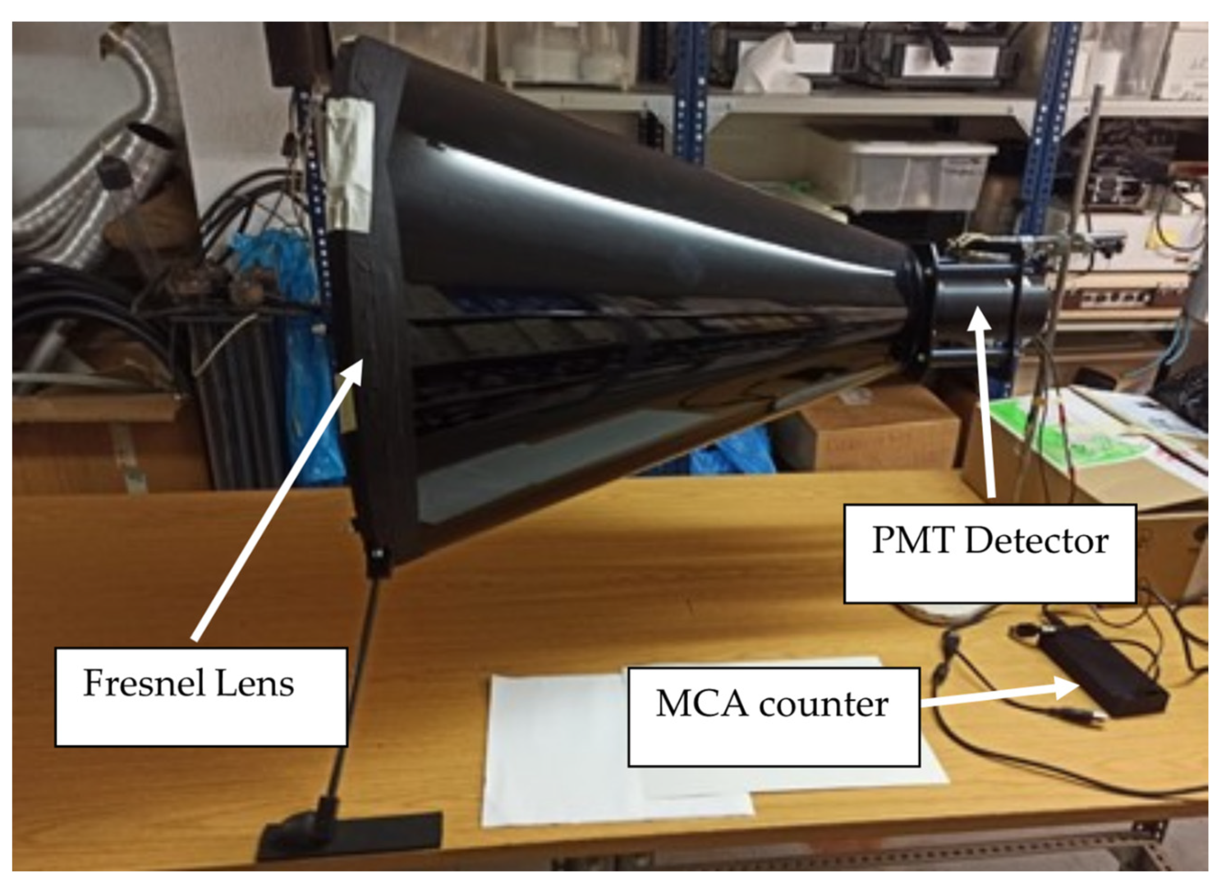
This section describes all the equipment used during the project to perform the alpha particle detection flights and explains the specific role of each instrument or sensor.

2.1.1. Detector

The initial step was to design and build an optical alpha detection system mountable on a commercial UAS. The detection of the light emitted by the radioluminescence resulting from the interaction of alpha particles with air comprises several phases. The first phase is to collect the emitted light (light collection); in the intermediate part, the wavelength of interest (UV-C) must be filtered out (photon filtering); and finally, the number of photons arriving at the detector must be counted (photon counting).
The radioluminescence light is collected by a Polymethyl-methacrylate (PMMA) Fresnel lens with a diameter of 452.9 mm and a focal length of 424.5 mm chosen to ensure a high light throughput in a manageable form factor [17]. Photon filtering is performed with 3 Semrock FF01-260/16-25 interference bandpass filters centered at 260 nm with a bandwidth of 16 nm. To achieve the best UV-C band filtering, a set of two fused silica corrective lenses (Thorlabs LC4252 [18] and LA4052 [19]) were installed to parallelize the collimated photon beam. An additional filtering performance was achieved by tilting two filters in the set by 3 degrees relative to the optical axis.
Photon counting is performed with a photomultiplier tube (PMT) detector, which converts the incident light into an electrical signal, which is analyzed by a digital pulse processing unit. The detection system uses the solar-blind Hamamatsu H11870-09 photomultiplier tube [20] with transistor–transistor logic (TTL) output and the GBS Elektronik MCA527 OEM+ multichannel analyzer [21] working in the scaler (gating) mode to translate these TTL signals into the timestamped count rate. During the flight, the count rate is polled and transmitted to the GCS to be displayed on a map for subsequent interpretation. If the count rate exceeds the threshold determined by the background rate, the source is present in the detector’s field of view.
A carbon fiber-reinforced cone-shaped polymer frame was built to hold the lens and the detection system. The frame materials were chosen to provide the necessary stability for the system while keeping it lightweight. The detector has a height of 790 mm and a diameter of 520 mm at the base. Figure 1 shows an image of the detector and its different parts in a horizontal position during laboratory tests.

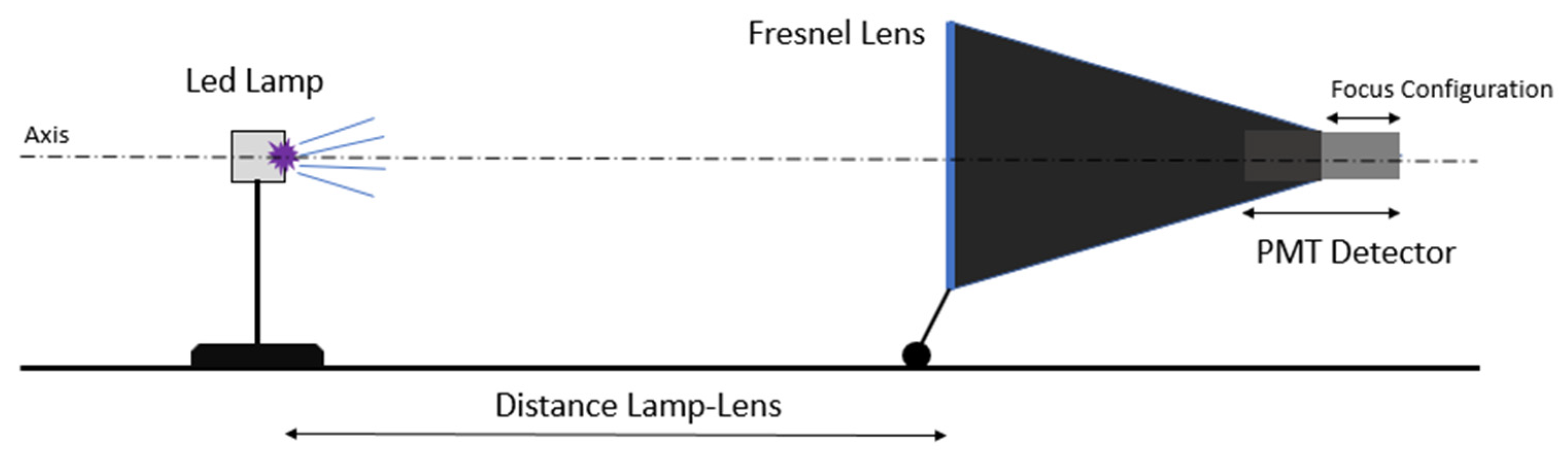
2.1.2. Characterization of the Detector

Investigation of the detector response was first performed under light-controlled conditions with UV LEDs to determine the field of view (FoV) and the best focusing configuration for the flights. In addition, the change in efficiency as a function of the angle of incidence and the power of the LED lamp was investigated. The results of these experiments are presented in Section 3.
The LED lamp used to test and optimize the optical system had a 5 mm thick Teflon disc at the exit aperture and was calibrated with a 210Po activity standard. The LED lamp allows 12 different power modes, from numbers 0 to 11 (see Figure 2), simulating alpha sources with an energy of 5.4 MeV and activities up to 7.3 GBq (setting Nr. 11).
The optical system has a sliding detector design that allows for adjusting the focus according to the object distance. The efficiency of each focusing configuration, represented by the detector position F (protrusion from the frame in centimeters), was tested with the LED source placed on the optical axis at various distances, as illustrated in Figure 3.
The field of view (FOV) is defined as the diameter of the spot that can be seen by the optical detection system. It depends on the focal length of the used receiving optics and the object distance. While in the simple lens–PMT case, the FOV can be estimated with a formula, the use of corrective lenses and non-trivial filter allocation required experimental evaluation. To determine the field of view, the LED source was moved perpendicularly to the optical axis.
The FOV is calculated by fitting the experimental data to a Gaussian function. The amplitude A and the standard deviation σ are calculated. The FOV is defined by the integral area in the [−2σ, +2σ] range, which includes ca. 95% of the total light collected.
The angular field of view (AFOV), the angle at which the detector can collect the light, is another important metric for drone-assisted optical measurements. It is calculated from the FOV and the distance between the object and the lens:
AFOV = 2 · atan FOV / 2 d
To assess how the tilt of the UAS can affect the light collection efficiency, the radioluminescence signal is measured as a function of the angle between the Fresnel lens optical axis and the UV LED axis using a rotating platform with 1° precision.
This was the method used to calculate the field of view of the detector, the appropriate focus setting, and the count rate values provided by the LED source. Section 3 details the graphs obtained from these experiments in the laboratory.

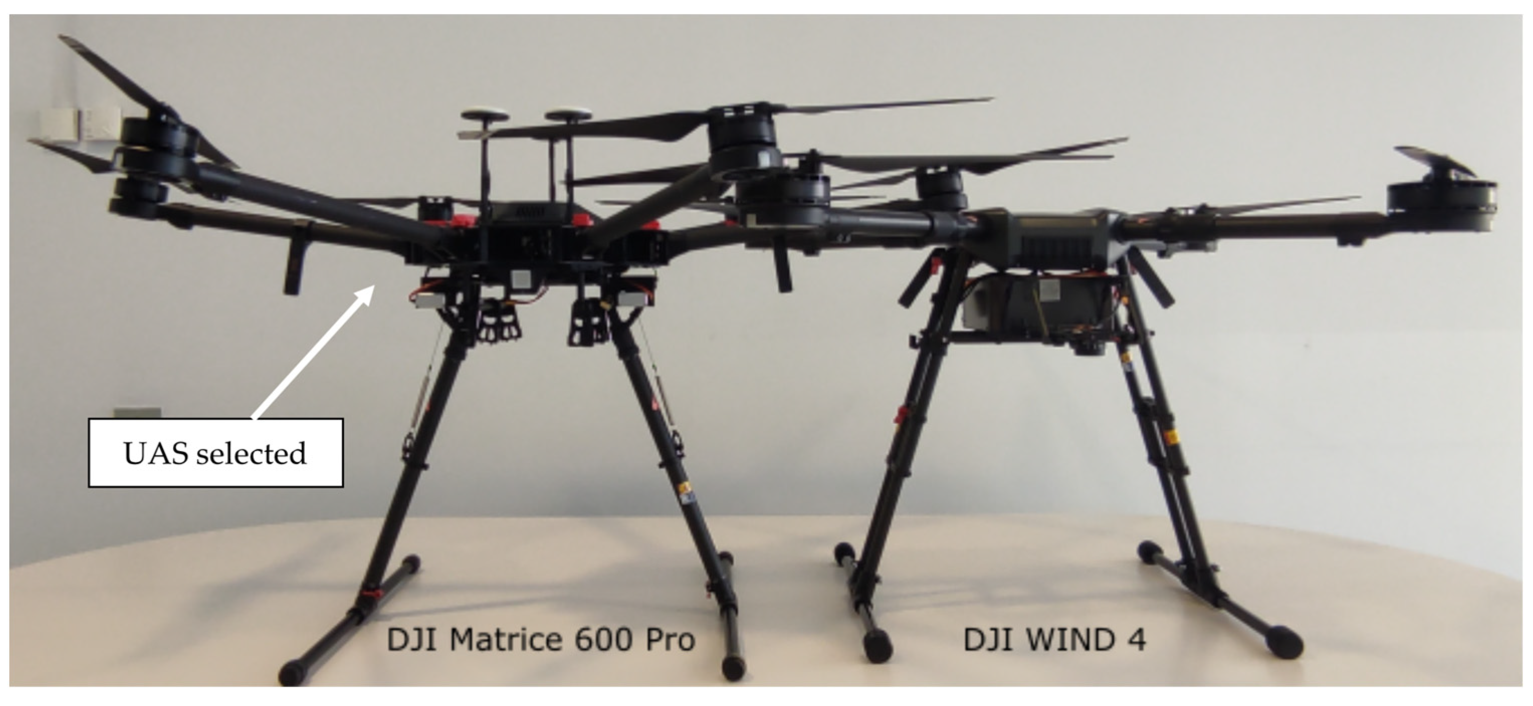
2.1.3. Unmanned Aircraft System (UAS)

Given the dimensions of the detector (see Figure 4), no commercial UAS was large enough to natively integrate the detector under its belly, since the height of the detector is larger than the UAS’s legs. This made it difficult to integrate the detector into a commercial UAS unless the detector itself acted as the landing gear. Therefore, four legs were attached to the detector so that the structure of the Fresnel lens is used as the landing gear of the unmanned aircraft. Figure 4 shows the Fresnel lens detector structure with a scheme of the landing legs and their dimensions.
Table 1 displays a summary of the weight of each UAS payload element and the sum of all components.
Two UASs from the Technical University of Catalonia (UPC) fleet were selected as possible candidates to mount the payload described in Table 1: DJI WIND 4 (W4) and DJI Matrice 600 Pro (M600P) [22]. Figure 5 shows pictures of both UASs. The authors have extensive experience with the M600P flight detector for radiological measurements, as it was used in previous projects, such as “Preparedness” [3,4]. In addition, the M600P incorporates newer flight technology than the W4. For instance, the M600P is equipped with the A3 Pro flight controller, which improves control accuracy while increasing overall safety. On the other hand, the W4 has a better payload weight and flight autonomy than the M600P. However, the landing legs of W4 suffer from mechanical stress at high payloads. Another drawback of the W4 is the placement of the batteries, which would make the integration of the detector into the UAS more difficult. Given the extensive operational experience, the improved avionics of the UAS, and easy payload integration, the M600P was chosen to mount the radioluminescence detector.
Since the M600P was not equipped with a real-time kinematic (RTK) system, which greatly enhances the positioning accuracy, especially in the vertical profile, the Lightware SF11/C laser altimeter [23] was installed on the UAS. This altimeter has a long range (100 m), fast update rate (20 readings per second), and lightweight (35 g) laser designed specifically to be used on a UAS. The M600P technical specifications provided by the manufacturer, without RTK, indicate that the UAS has a vertical flight accuracy of ±0.5 m; however, the accuracy of the laser altimeter is 0.1 m.

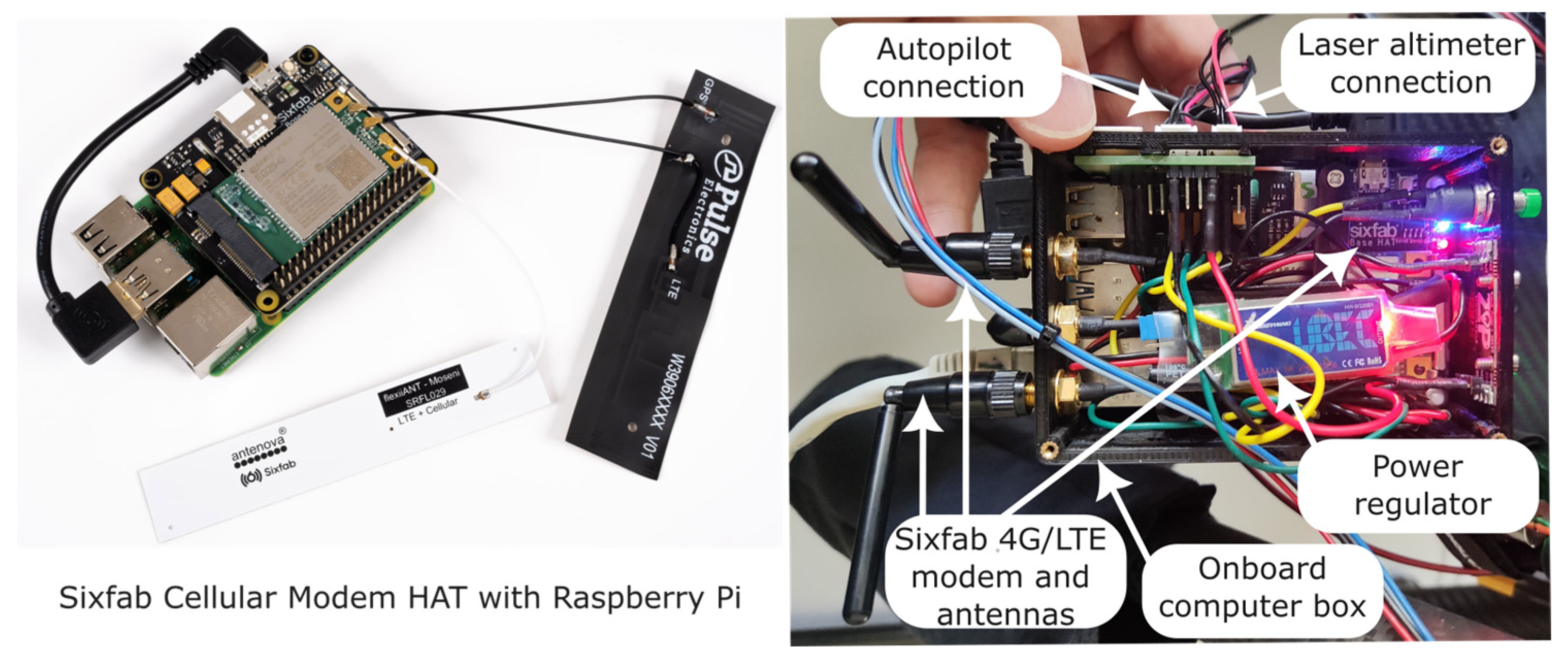
2.1.4. Onboard Computer and Air–Ground Communications

Each measurement carried out with the optical detector must be geo-tagged during the flight for near-real-time mapping. For this task, the onboard computer fuses UAS telemetry and detector count rate data. The optical detector can provide a count rate measurement every 100 milliseconds. When the term “near real time” is used in this paper, it refers to the ability of the ground operator to observe in-flight measurements as they occur, without implying that the entire system responds within a specific fixed time frame. Typically, this time frame ranges from a few milliseconds to one or two seconds in the worst cases with very low communication coverage. The system’s response time variations do not affect the application’s normal functioning and normal monitoring of the measurements taken.
The Raspberry Pi 4 Model B was chosen as the onboard computer [24]. This single-board computer is excellent for prototyping due to its low weight, large number of ports for connecting devices, and large support community. The Raspberry Pi 4 Model B has a Quad-core Cortex-A72 (ARM v8) 64-bit SoC with 1.8 GHz and 8 GB SRAM. The board also features 2.4 GHz and 5 GHz IEEE 802.11ac wireless LAN, Bluetooth 5.0, two USB 3.0 ports, two USB 2.0, Gigabit Ethernet, and an extended 40-pin General-Purpose Input/Output (GPIO) header, where six UARTs can be found. Two of the six available ports are used. One of the UARTs is connected to the UAS autopilot to receive its telemetry and extract its current position and UAS attitude. The second UART port is used to connect the laser altimeter to obtain an accurate altitude.
Air–ground communication with the onboard computer is performed through the Sixfab Raspberry Pi 4G/LTE Cellular Modem Kit [25]. The kit provides all the components for establishing an Internet connection on the Raspberry Pi. This allows interaction with the onboard computer at any given time, in near real time, and from anywhere in the world, as long as it is connected to the Internet. Through this connection, the geo-tagged measurements taken by the detector are sent to the ground control station.
The onboard computer and 4G/LTE air–ground communications are powered using the UAS’s batteries. The M600P has a connector that provides an 18 V-7 A power output. The voltage must be converted to 5 V to power the onboard computer, for which a HOBBYWING regulator capable of providing 5 V and 3 A was used. Figure 6 shows the integration of the Raspberry PI, the 4G/LTE model with its corresponding antennas, and the voltage regulator. It also shows the connection of the autopilot and the laser altimeter (right panel).
The system presented in this work is the first prototype. It has been assumed that 4G/LTE coverage will always be available to communicate with the UAS in order to avoid adding more complexity. However, in the event of a nuclear catastrophe, where the 4G/LTE network may not be available, an auxiliary point-to-point communication system that does not rely on the 4G/LTE network should be available, for instance, a radio modem system using the 868 MHz ISM band for Europe or the 900 MHz ISM band for the United States.

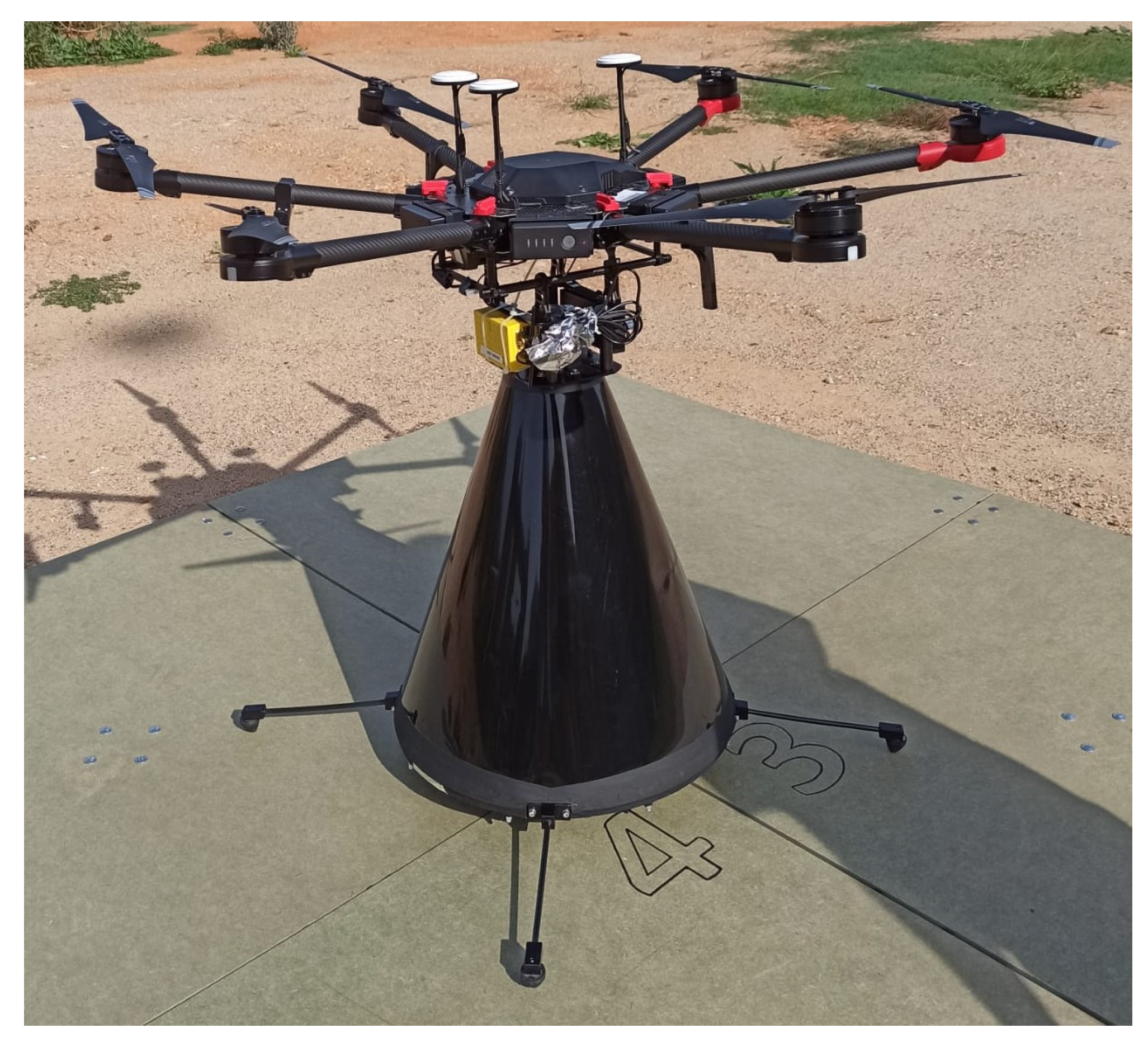
2.1.5. Hardware Integration with the UAS

The alpha radioluminescence detector with the landing legs, the MCA counter, the laser altimeter, and the onboard computer with a 4G/LTE modem were integrated with the M600P, as shown in Figure 7. The figure also displays the flat landing pad required for the takeoff and landing of the assembled UAMS due to the low clearance between the lens and the ground.
The following subsections describe the radiation and ultraviolet (UV) sources used during the test and validation flights.

2.2. UV Sources

To verify the operation of the system, it is necessary to check it in conditions where alpha radiation sources or similar are present. The problem with using alpha radiation sources lies in the stringent radiation protection protocols for both the airfield and the transport to the test site, which limits the flexibility of outdoor testing. Although alpha sources were used during the final flights, in many preliminary tests, they were replaced by LED sources that simulate the UV emitted by the air radioluminescence.

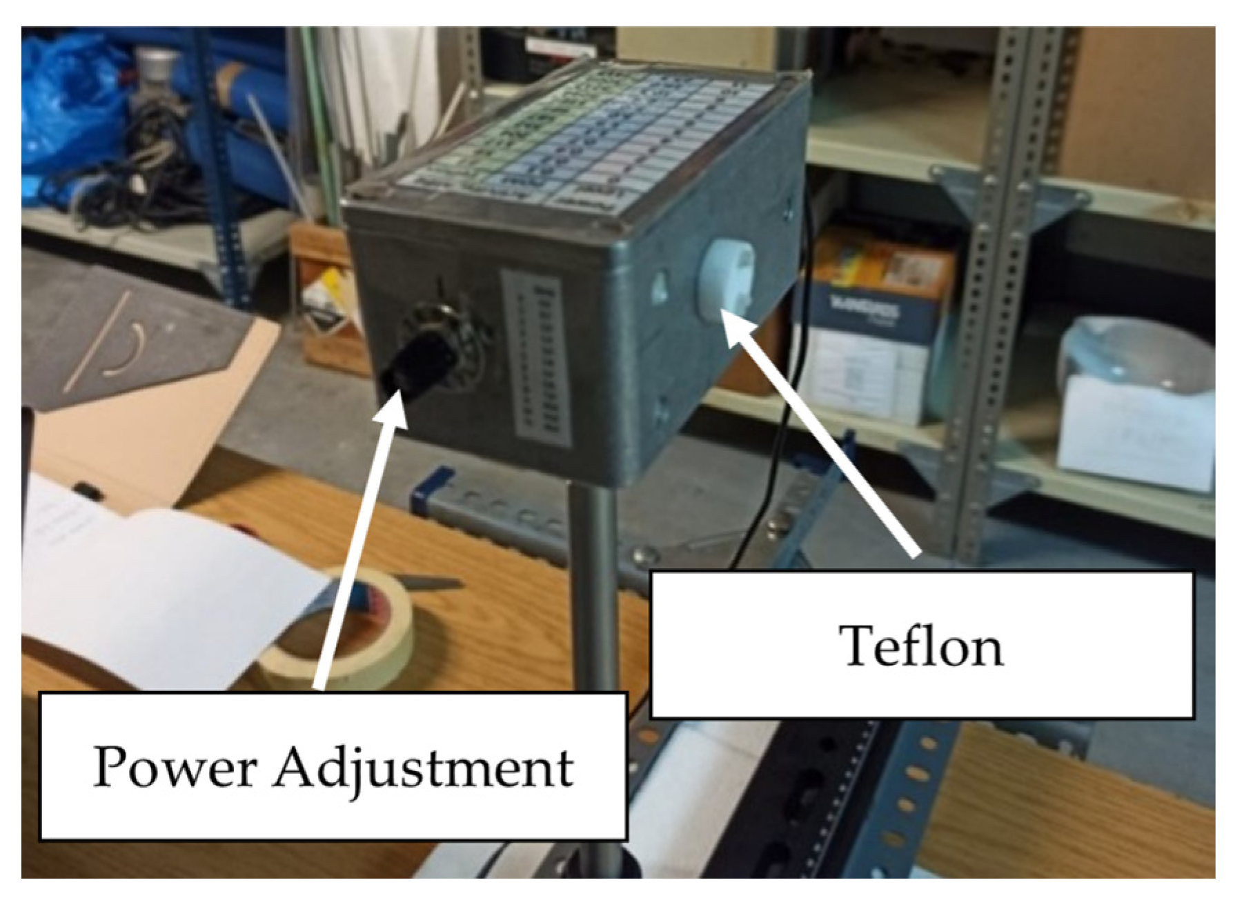
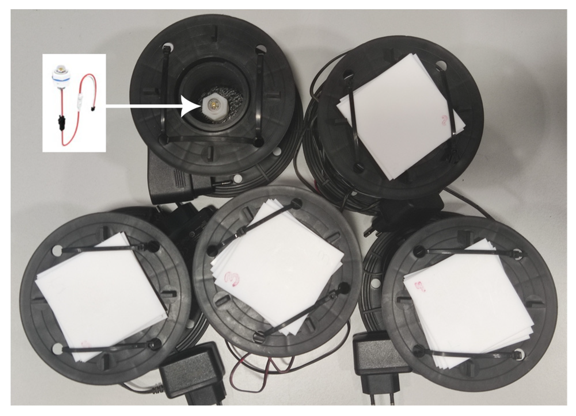
2.2.1. UV-C LED Sources

The UV-C LED sources used in the flights are commercially available and commonly used for the water purification, disinfection, and sterilization of home aquariums. The LED has a peak wavelength between 270 nm and 280 nm and a radiant flux of 8 mW. Teflon sheets of a few millimeters are used to moderate the radiant flux to a level representative of radioactive sources that could be found in an emergency scenario. In addition, Teflon sheets serve to diffuse the light, increasing its angular spread.
As per Section 3.1 results, the calculated FOV of the detector of only a few centimeters makes the detection of point sources significantly more complex than in the case of an extended-source scenario. To analyze the detection probability of point sources, five LEDs were fabricated, as shown in Figure 8. Therefore, five simulated alpha sources were distributed over the flight area to test the performance of the system in detecting point sources.

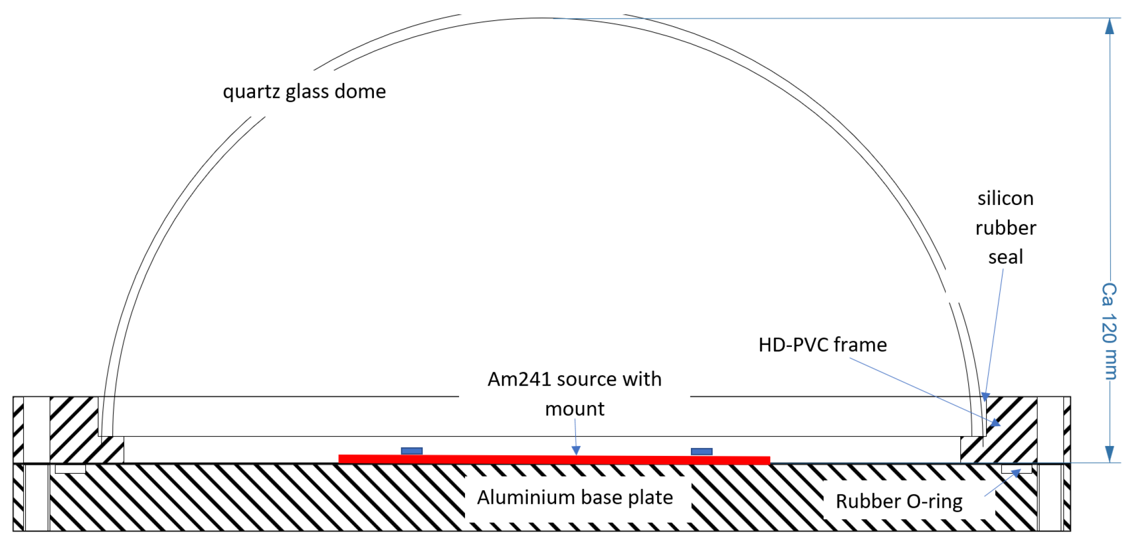
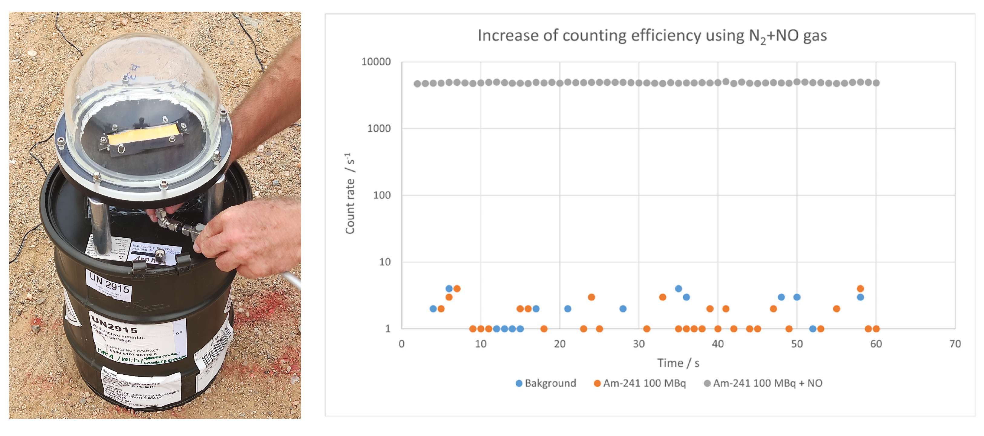
2.2.2. Americium Source

The reference alpha source used in the flights was manufactured by Eckert & Ziegler Cesio s.r.o (Prague, Czech Republic). The provided sealed foil of the 241Am source had an activity of 100 MBq (activity tolerance: +0%, −30%). 241Am is an alpha and gamma emitter [26], with the most probable alpha emission at 5485.56 keV (84.45%) and the most probable gamma emission at 59.54 keV (35.92%).
According to the manufacturer, the 241Am source consists of a thin AuPd layer into which an 241Am matrix of 1 µm thickness has been homogeneously incorporated. The source has an overall thickness of 0.25 mm consisting of a silver backing and a very thin layer of gold (<2 µm thickness) covering the alpha-emitting face. The lateral dimensions of the foil are as follows:
  • Active dimensions: 20 mm × 100 mm.
  • Overall dimensions: 30 mm × 100 mm.
To fulfill the radiation-source-handling requirements, the 241Am foil was mounted on an aluminum base plate and covered with a quartz dome that is optically transparent to the radioluminescence produced by alpha particles in the air (see Figure 9 and Figure 10). The chamber design allows it to be evacuated to approximately 1 hPa and purged with gas at pressures up to 1000 hPa (environmental pressure).
From the radiological point of view, this enclosed source is considered sealed, and the only concern is the external exposure to 241Am gamma emissions. The 12 cm high dome, with a 5 mm thick wall and nominal outer diameter of 20 cm, provided a barrier to avoid the dispersion of the radioactive material in case of an incident. The ambient dose equivalent rates, Ḣ*(10), measured for the 100 MBq source in contact with the dome wall, were 30 µSv h−1 (top of the dome) and 15 µSv h−1 (lateral position). An exclusion zone of 2 m around the sources was applied during the tests in the field to further reduce radiation doses to all personnel to the level of the background ambient dose equivalent rate level (0.1 µSv h−1).
The LEDs and the 100 MBq 241Am source purged with a N2 + NO gas mixture were used for the test flights with the Fresnel lens detector performed in the Drone Research Laboratory (DroneLab) [16]. The left side of Figure 10 shows the way the gas was administered to the americium source, and the right side of the figure shows how the count rate increases when the source is purged.

2.3. Software Architecture

The presented hardware uses a software architecture, called RIMASpec 1.0, that has already been used in previous gamma detection projects [3,4]. For the RemoteALPHA project, the software was upgraded to visualize a map of alpha-emitting radionuclides in the environment in near real time.
Figure 11 illustrates the software architecture of the aerial and ground segments. The diagram displays how the software services cooperate to geolocate the detector measurements, record them in a CSV file, and send the data to the ground control station for display on a map. Communication between the ground and air segments is managed by a server using the MQTT protocol [27]. The UAS operation and data visualization from the ground station are performed via the developed web browser application.

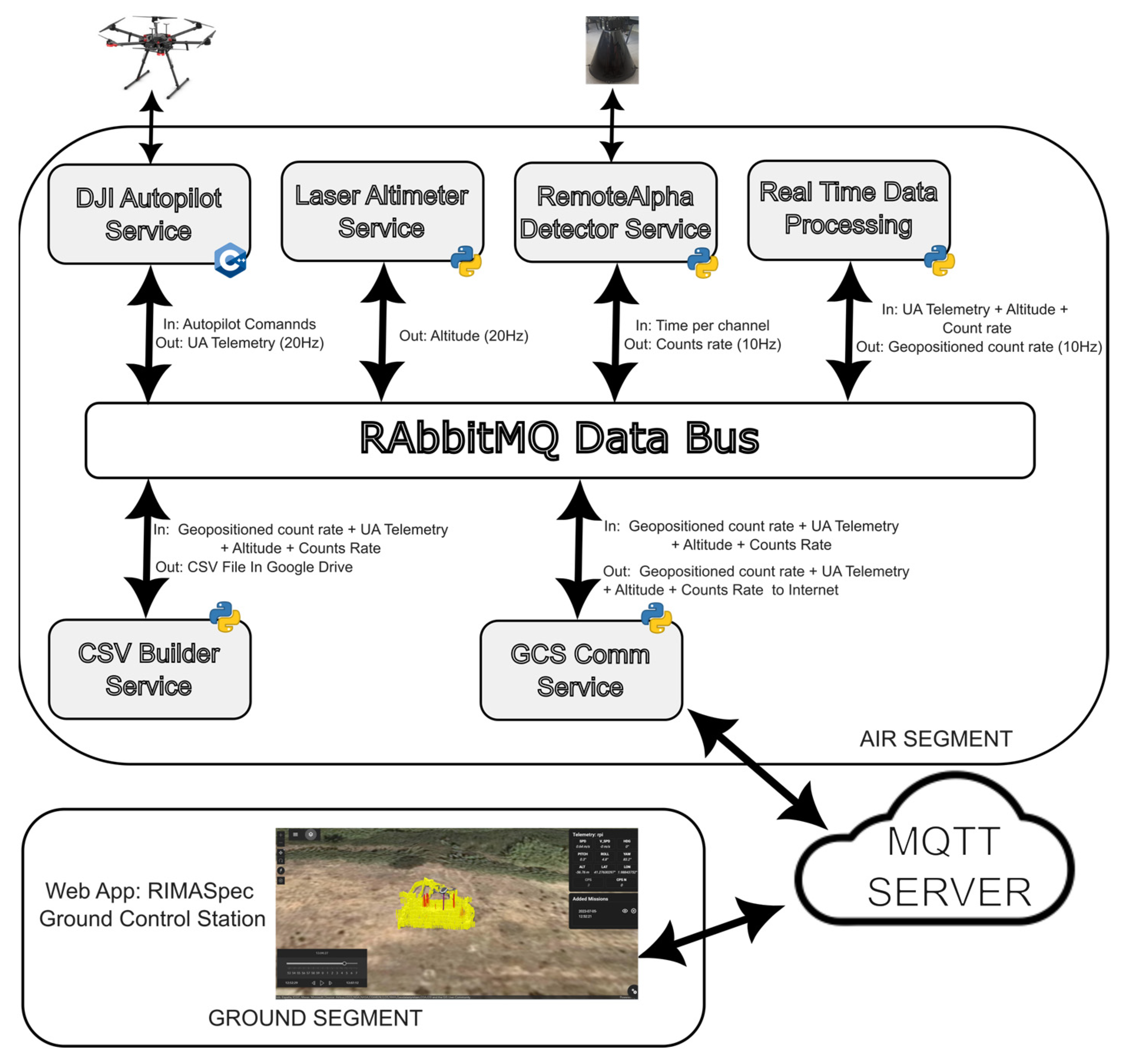
2.3.1. Air Segment Software Architecture

This subsection details the operation of the air segment and the role of each service. The air segment is a distributed system where each service has a specific functionality that must be fulfilled for the whole system to work. The air segment software operates on the Raspberry Pi 4 board using the Raspberry Pi OS version 5.15.32 (previously known as Raspbian), which is the officially supported operating system.
The different services exchange information through a data bus. RabbitMQ version 3.11—a message-queueing software that uses the publish/subscribe paradigm [28]—is used as a data bus. RabbitMQ facilitates the transfer of messages between connected processes: services can publish information to the bus, allowing other services interested in that information to subscribe to it.
The air segment operates as follows: The software service in charge of interacting with the UAS autopilot, called the DJI Autopilot Service, publishes telemetry to the data bus at a frequency of 20 Hz. At the same time, the service in charge of managing the laser altimeter, called the Laser Altimeter Service, publishes the UAS altitude to the data bus with a frequency of 10 Hz. Finally, the RemoteAlpha Detector Service publishes the detector’s count rate every 100 ms. The Real-Time Data Processing Service subscribes to all this information and merges the data. In the process, it selects the best UAS telemetry sample to geoposition the detected count rate. Once the data have been joined together, this same service publishes the geo-tagged count rate to be saved in a CSV file by the CSV Builder Service and sent to the ground control station by the GCS Comm Service using the LTE (4G) network.

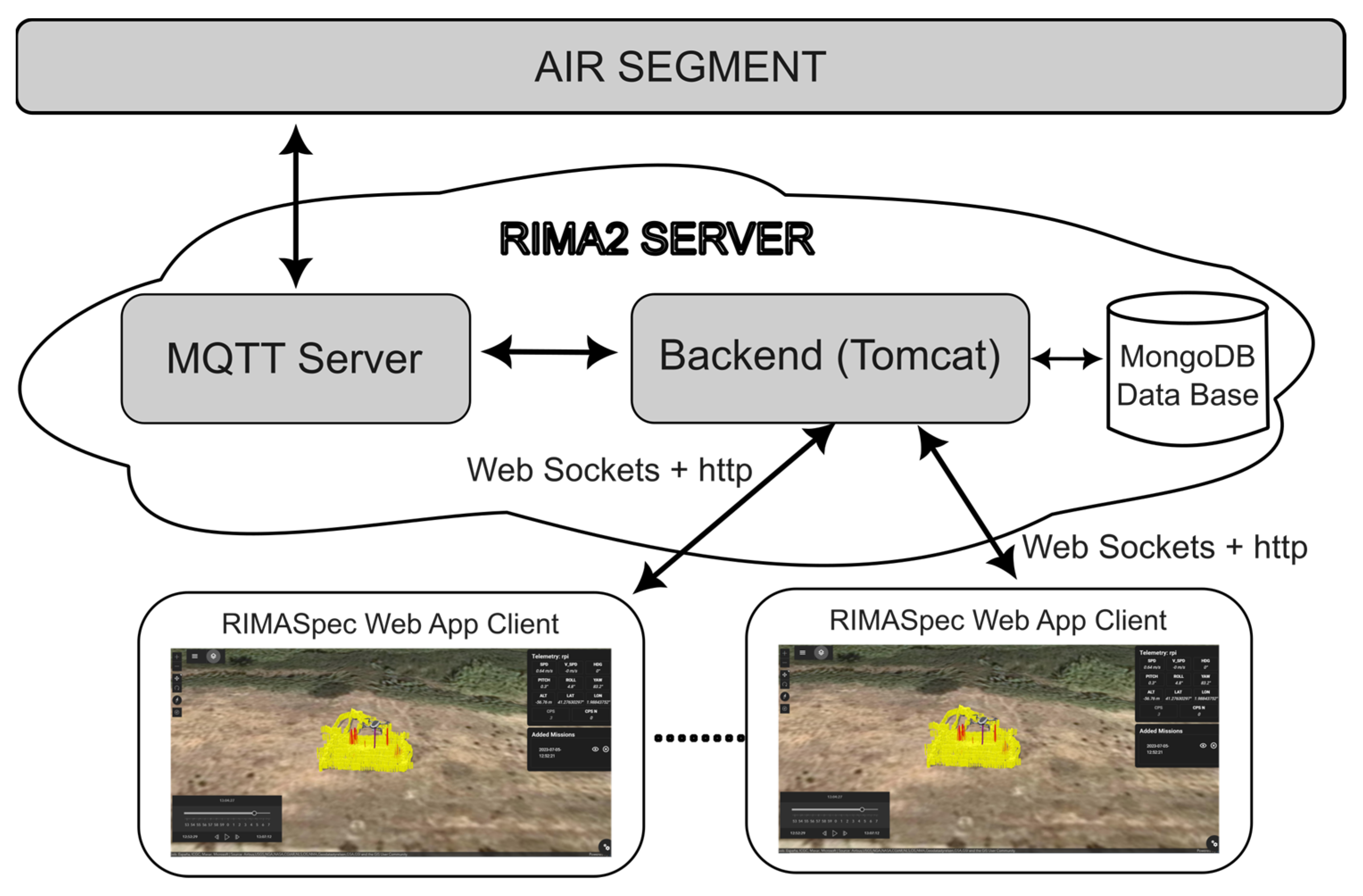
2.3.2. Ground Segment Software Architecture

To visualize the count rate on a map in near real time, a web application was developed. This web application has a backend and a frontend, as shown in Figure 12. The backend has been developed using the Apache Tomcat Server (https://tomcat.apache.org/, accessed on 21 February 2024). Apache Tomcat is a popular open-source web server and Servlet container for Java code. For this work, this server was hosted on the same machine as the MQTT server. The backend is subscribed to the MQTT data, through which all the information from the air segment arrives. The air segment information is processed and ready to be displayed on the different web browser clients (frontend). The communication between the backend and the frontend is facilitated through web sockets and HTTP queries.
The web application allows any computer with an Internet connection and a browser to access the application using a username and a password, requiring no additional software installation to run the RIMASpec ground control station. The web application has a database (MongoDB version 3.6.8) where the users are created and where all the measurements taken by the drone are stored. The application has three user types: the administrator, the operator, and the viewer. The viewer type is intended for users who are only interested in radiological information. In the role of operator, the user has control over the UAS. The administrator can manage user profiles on top of the previously described functionality.
Once logged in, the screen shown in Figure 13 appears with three panels representing application options.
Panel 1 has the tools needed to create and edit a flight plan for the UAS. Through this panel, the user can create or edit an operation area and save it in a file. Then, the software can generate a flight plan over that area: for example, a random flight plan or a flight plan with different parallel tracks. Some of these flight plans are shown in Section 3. Panel 2 presents the tools used to work with the map. This panel allows zooming in and out on the map or centering the map at the UAS location. Finally, Panel 3 alerts the user when it detects a UAS that wants to connect to RIMASpec.
As mentioned above, all flight and detector data are stored in the database, and RIMASpec can replay previous flights, as shown in Figure 14, which displays a screenshot of a flight performed in December 2022. The color and height of the cylinders indicate the counts measured in 0.1 s. The color range and height of the cylinders can be modified to optimize the visualization of the source detection. The detected counts can also be read numerically in the right-hand data box. In this data box, the UAS telemetry is also displayed: speed, pitch, roll, yaw, longitude, latitude, and altitude. Behind the telemetry box, the command box is placed, which contains the dialog for each possible command that can be sent to the UAS. The visualization software also shows the UAS position and the location on the ground where the detector is pointed (violet line). In addition, the UAS path can also be shown on the map but is hidden in Figure 14 to better see the count rate markers.
The RIMASpec software has more extensive functionality beyond the application-related features shown here, such as user management tools, layer visualization, and flight plan editing.

3. Results and Discussion

Before performing the flights with the developed sources (LED and 241Am), the Fresnel lens detector had to be calibrated in terms of the counting efficiency and the field of view. This was necessary since both these parameters are crucial to designing the optimal flight plans to localize the alpha sources.

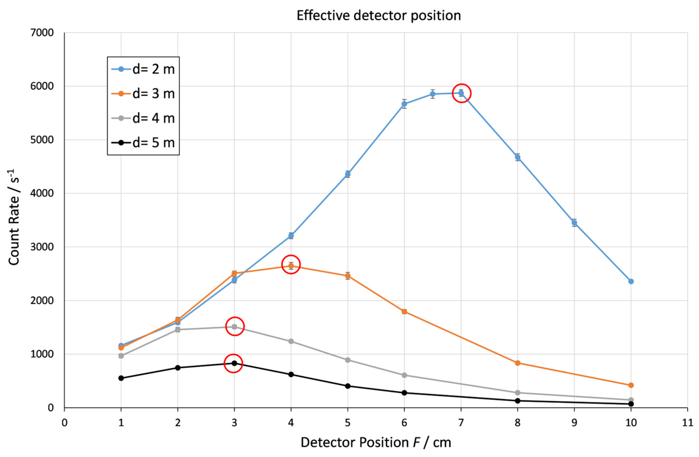
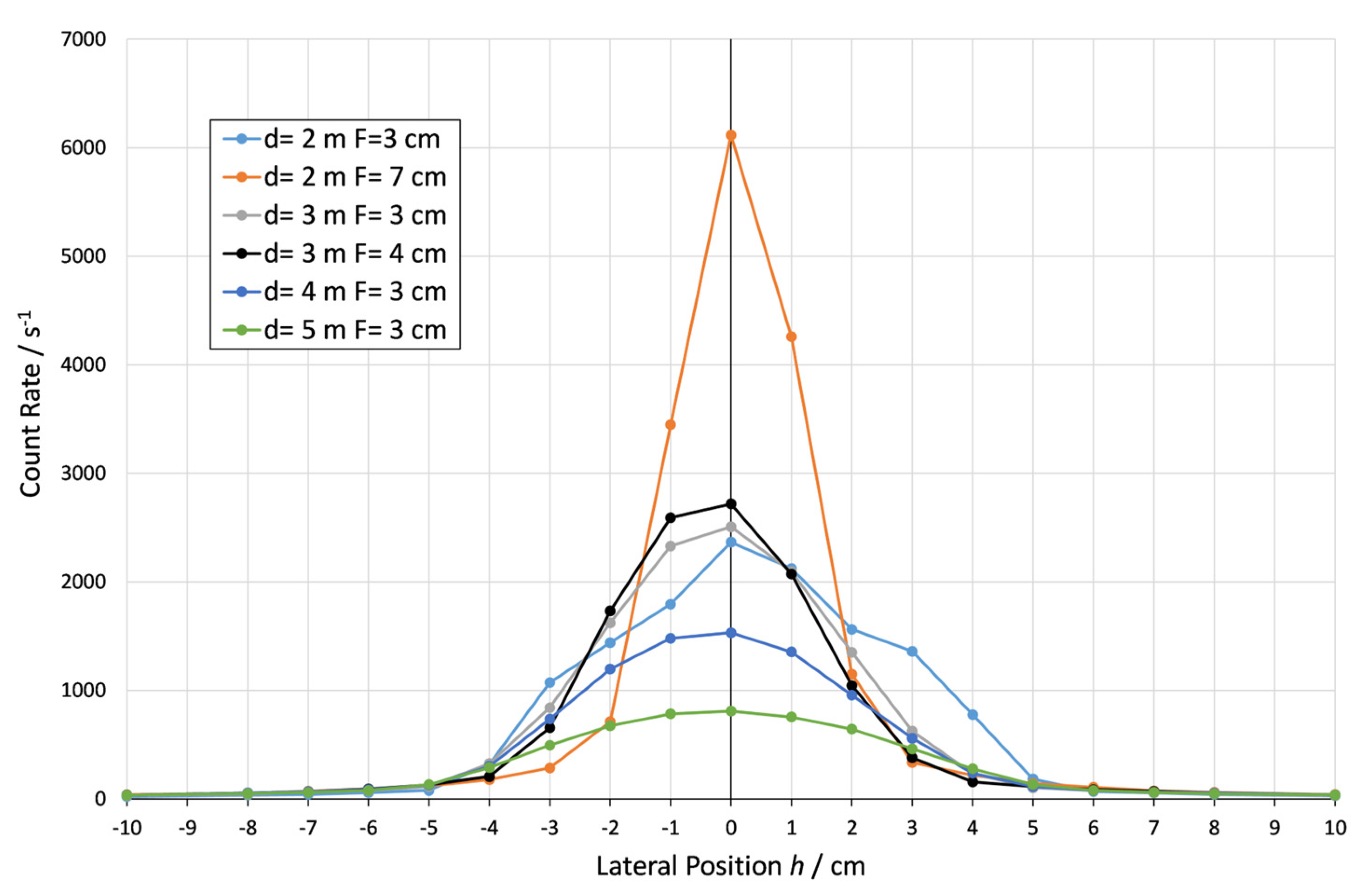
3.1. Focus Configuration and the Field of View

The measurement setup illustrated in Figure 3 has been used to obtain the optimal focus configuration, the detector FOV, and the efficiency. The LED source was placed at a distance d ranging from 2 m to 5 m from the Fresnel lens. The PMT position F defines the detector protrusion from the frame (see Figure 3), which is easily measured with a ruler and represents the focal length according to the following formula:
F = f 40.2   cm
The position F was varied in the range from 1 cm to 10 cm during the tests. The results of the count rates measured at constant LED power simulating 7.3 GBq are shown in Figure 15, with the most effective measured detector position marked with a red circle.
Figure 15 shows the influence of the detector position F on the detected counts for a point source located on the optical axis of the lens. At a distance of 2 m, the detector measures approximately 6000 s−1 at the optimal position between 6 cm and 7 cm; at a distance of 3 m, the count rate drops to 2500 s−1, and F is between 3 cm and 5 cm. At larger distances, the optical detector position F is approximately 3 cm. The maximum count rate at a 5 m distance is around 800 s−1. The dimensions of the laboratory did not allow testing longer distances.
Figure 16 shows the count rates measured for every lateral position h (perpendicular to the optical axis shown in Figure 3) of the LED source used to calculate the FOV and AFOV of the system at different distances from the source and focus configurations F. These parameters were estimated from the Gaussian fits of the corresponding lateral profiles (see Table 2). From Table 2, it is apparent that the FOV is relatively small: for a distance of 5 m and a focus configuration of 3 cm, the FOV is 10.7 cm.
Figure 1 shows the count rates measured at different source–lens distances and lateral positions from the optical axis.
For the scenario where there are point alpha sources, the flight plan tracks should be very close together, the speed of the UAS should be very low, and the integration time should be short to maximize the probability of detecting them. Another concern with this type of scenario is that the UAS is not always completely perpendicular to the ground due to variations in wind and UAS speeds, resulting in changes in the roll and pitch of the whole flying system. These variations in the roll and pitch of the UAS reduce the number of counts acquired compared to a vertical position that is completely aligned with the ground. On the other hand, this variation in roll and pitch increases the probability of detecting the source because the area covered by the detector is larger than when the UAS is in constant vertical alignment.
In the case of an extended source, the detection efficiency can be obtained by laboratory calibration. In this case, the uncertainties of the detector pointing vector are not significant for the source detection and the activity calculation. In such scenarios, the detection count rate per unit activity, i.e., efficiency ε, given in units of s−1 MBq−1, and the FOV are used to calculate the detection efficiency per unit area εs, given in units of s−1 MBq−1 cm2:
ε s = ε   π   FOV 2 2
Table 3 and Table 4 list the detection efficiencies and corresponding source activities calculated according to the Table 2 data for an extended source. With relative uncertainties of the LED source and FOV of 10%, the estimated uncertainty for εs is about 22% [29].
Figure 17 juxtaposes the efficiency per unit area for F = 3 cm and F = MAX focus configurations at different source–lens distances. The reduction in the detection efficiency per unit area can be clearly seen for the F = MAX case: while the count rate is maximized due to the tighter focus, the FOV is reduced, resulting in a lower count rate per unit area compared to the focus configuration maximizing the FOV (F = 3 cm).
Finally, the decision threshold is calculated to decide whether there is a significant count rate increase that indicates the presence of an alpha source. Following ISO11929-4 [30], the decision threshold a *, with a 95% confidence level, is calculated with the following equation:
a * = 1.645 · u ~ 0
where ũ(0) is the standard deviation of background measurements.
During flights with high solar irradiance, typical of the Spanish region, the mean and standard deviation of the UV-C background measured with the Fresnel system is around 26 ± 28 s−1 for an integration time of 0.1 s. Therefore, the decision threshold to identify a possible alpha source is about 46 s−1. This net count rate represents a surface activity decision threshold of about 4.6 MBq cm−2 for an integration time of 0.1 s. The 100 MBq 241Am source with a 20 cm2 active area has an activity per unit of area of 5 MBq cm−2, which is too close to the decision threshold. Therefore, in order to detect the americium source, the radioluminescence intensity had to be amplified. This has been realized by purging the quartz dome enclosure with a N2 and 50 ppm NO gas mixture.

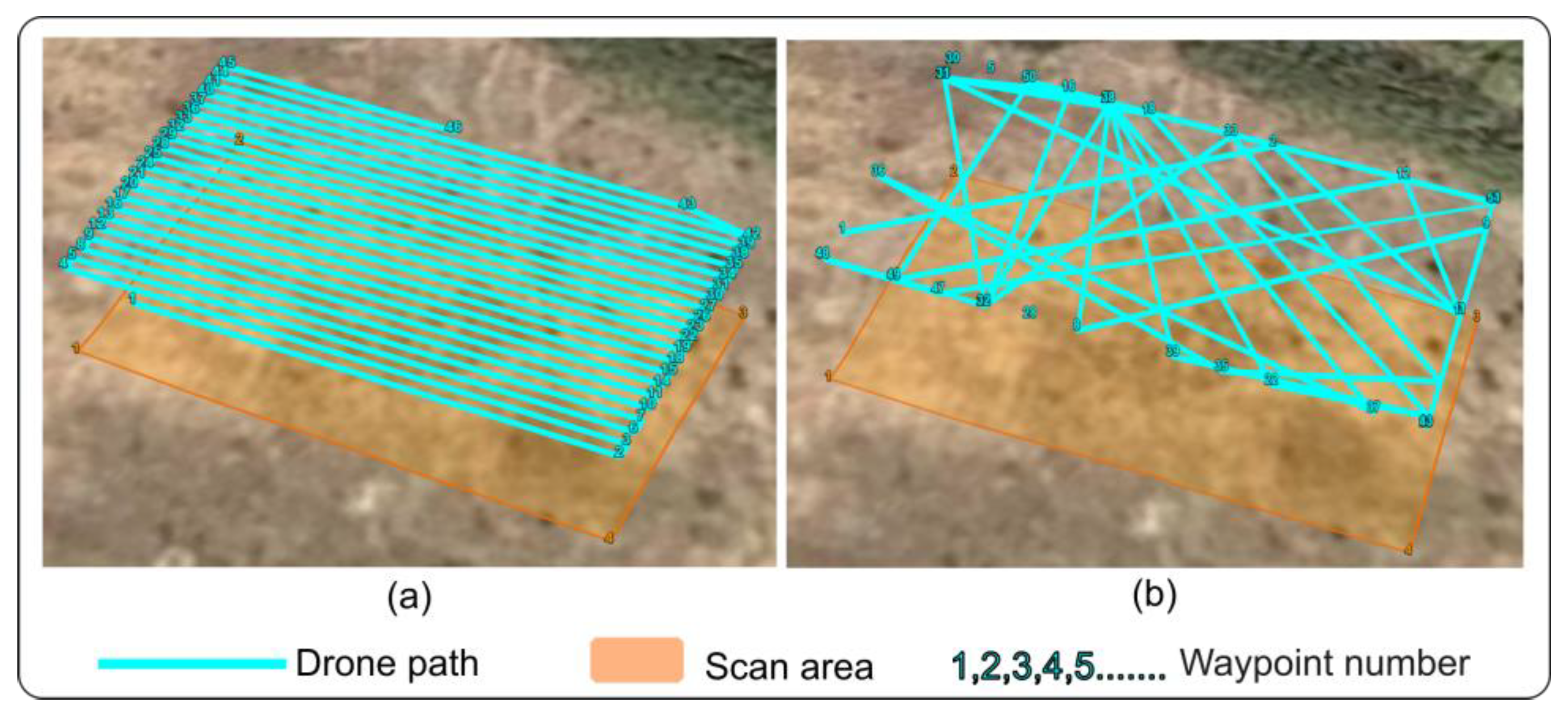
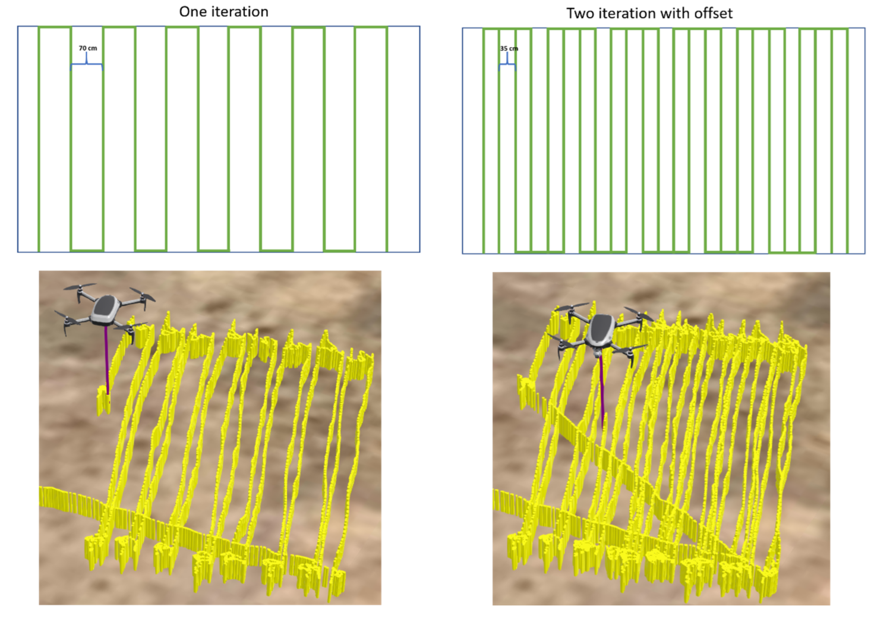
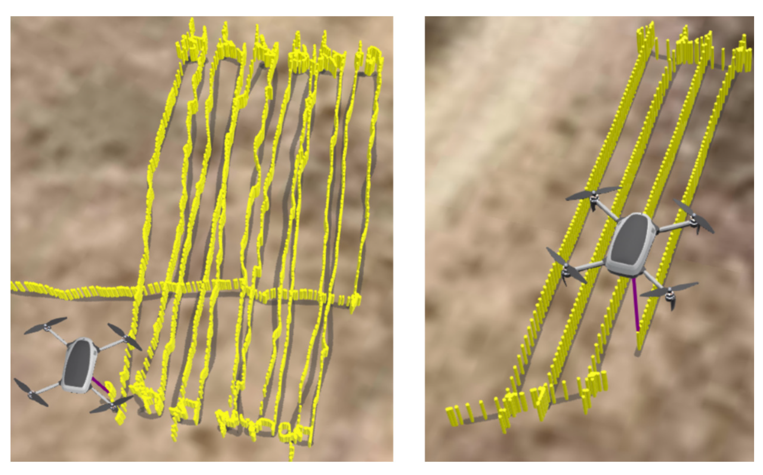
3.2. Optimal Flight Plans for Localization and Mapping of Alpha Emitters

Following the choice of the optimal height of 5 m described in the previous section, another crucial flight plan parameter, the flight speed, is considered. The flight speed is primarily determined by the field of view of the detector. With the FOV of about 10 cm, the measurement time of 100 ms necessitates flying at a speed of 1 m s−1.
The flight planner software module of the RIMASpec ground control station can generate flight plans for a UAS that cover an area with different patterns, such as back and forth (Figure 18a), random, and random with a genetic algorithm (Figure 18b).
For the test flights, a back-and-forth scan pattern was chosen to cover the whole area and to have a certain repeatability in the flight execution that the random algorithm does not offer. To cover the complete area, a distance between parallel lines of 10 cm needs to be used. However, the UAS does not permit placing waypoints in such close proximity; therefore, the shortest distance allowed by the UAS, approximately 70 cm, was selected. Given the manufacturer-specified horizontal positioning error of 1.5 m, it will be necessary to perform several iterations of the parallel line scan pattern with a small offset to ensure that the UAS passes through areas it omitted in the previous iteration. The upper panels in Figure 19 illustrate the scheme of two flight plans, while the bottom panels show real flights conducted according to this idea.
Each cylinder in Figure 19 corresponds to a measurement made by the detector. The markers are placed where the measurement was taken, meaning the projection is made toward the ground, taking into account the roll and pitch of the UAS. Figure 19 demonstrates how the measurements are accumulated at the ends of the flight plan tracks, where the UAS decelerates, stops, and changes its course to continue the path. It can also be observed that decelerating before the turn causes the UAS to perform measurements outside the flight plan due to the pitch change of the UAS. In the different lines of the flight plan, due to the small variation in roll and pitch and the wind effects, the measurements are not completely aligned with the flight plan, as mentioned before. These variations in roll and pitch, together with the GPS errors, make it very difficult to ensure that by following or repeating the flight plan, the whole area will be scanned.
This effect can be seen even more clearly when comparing a real flight with a flight performed with the manufacturer’s simulator. Figure 20 demonstrates the real and simulated flights side by side: in a simulation, the measurements are perfectly aligned.
Considering the mentioned challenges and uncertainties associated with the complete area coverage, the flights in the DroneLab were performed using the following parameters:
  • Speed: 1 m s−1;
  • Altitude above ground level: 5 m;
  • Distance between parallel lines: 70 cm;
  • Detector integration time: 0.1 s;
  • Scan pattern type: back and forth;
  • If the sources are not detected in the first iteration of the flight plan, a second iteration with an offset will be performed.

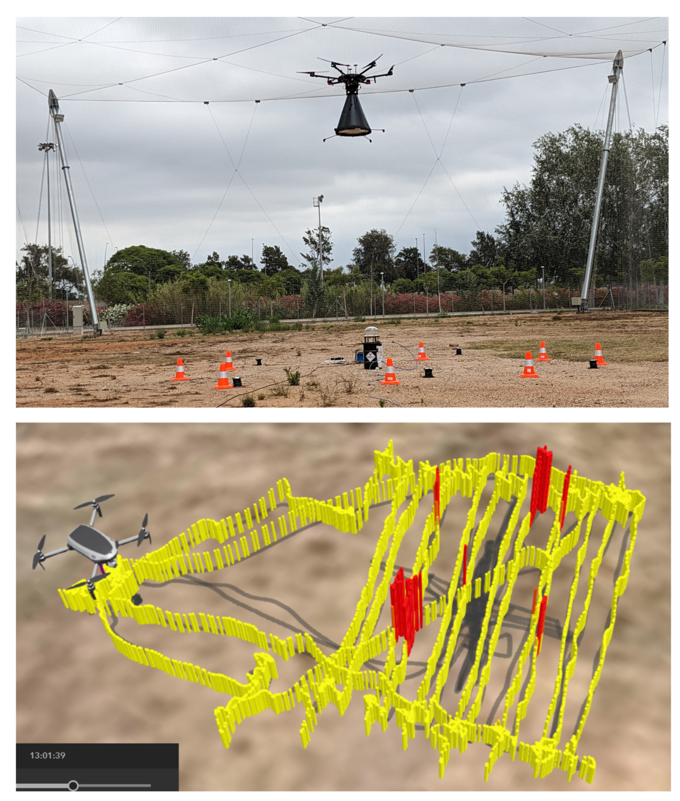
3.3. Defining and Preparing the Flight Area

The flights were carried out at the UPC’s Drone Research Laboratory (DroneLab), located in north-eastern Spain. The DroneLab is a research laboratory in the field of UASs that provides the infrastructure to carry out test flights, validation, and training for any kind of professional or research application based on a UAS. The infrastructure has an 80 × 45 × 15 m3 area, which is secure and separate from the general airspace, covered by a protective net that guarantees safety. The DroneLab allows flying in a controlled environment without the need for authorization from the authorities, despite being in an urban environment and close to the Barcelona city airport.
Figure 21 shows the flight setup with the LED placement and the takeoff/landing area that has been used in the different test flights during the project. The landing pad, made of artificial grass, protects the lens from any potential damage (e.g., dust particles) during landing and takeoff.

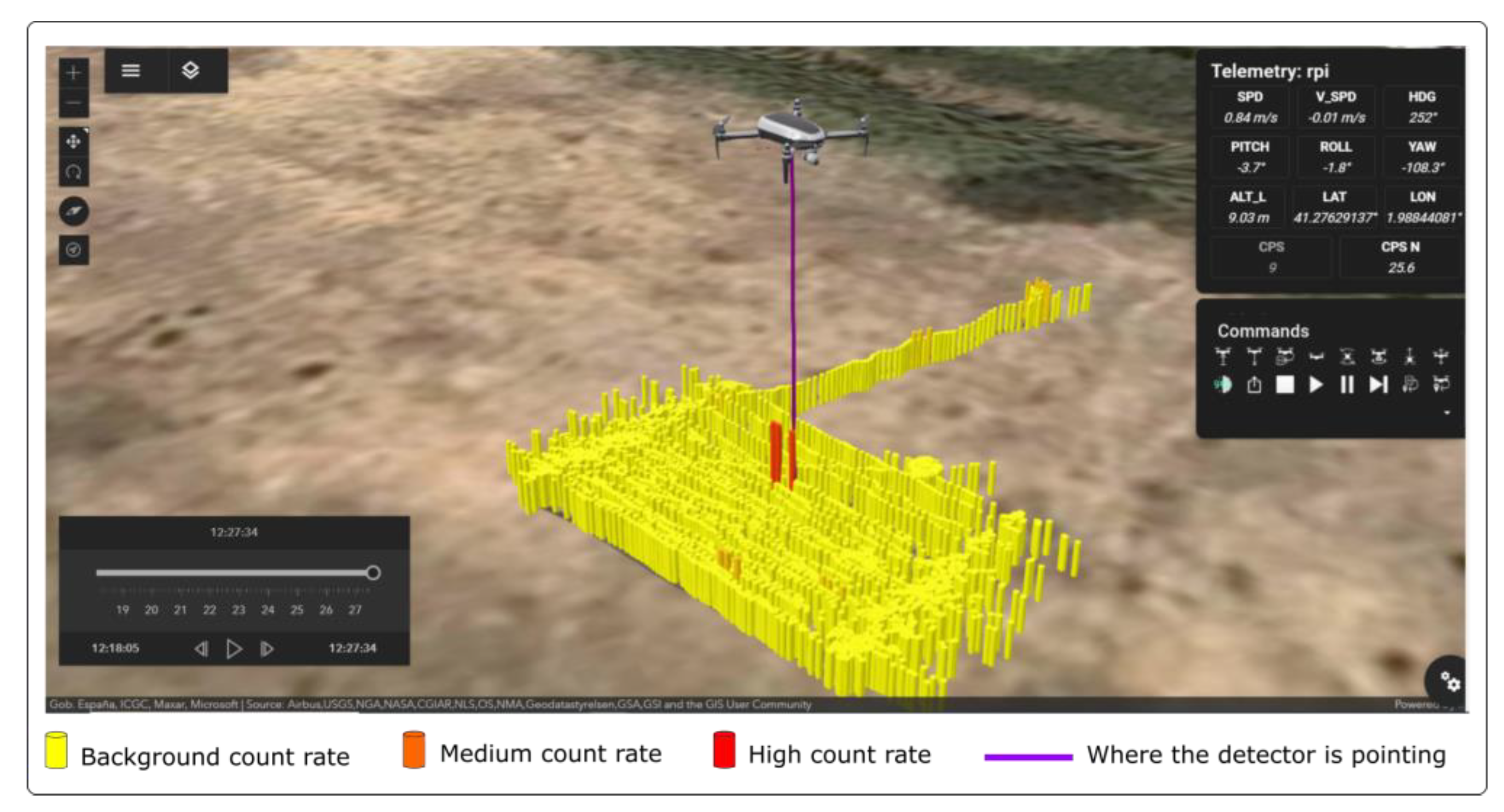
3.4. Flight Test with LEDs and 241Am Source

As mentioned before, due to GPS uncertainties and the wind effects (roll and pitch variations), the same flight plan repeated many times does not cause the UAS to fly exactly over the same place, and, therefore, the measurements are scattered between consecutive runs. Without this repeatability, it is very difficult to obtain the uncertainty of the source location of the point sources.
For instance, during experiments with five LEDs placed in random positions, not all of them were detected during the same iteration. During the first flight, three of the five LEDs were detected. Using the same flight plan in the following flights, either no LEDs or all of them were detected. Concluding the flight results, the probability of detecting a point source constitutes approximately 60%. This probability can be boosted by increasing the field of view of the detection system. However, increasing the FOV also has some other consequences, such as a reduction in the detector efficiency and background light leakage. Extended sources with larger lateral dimensions (e.g., on the order of GPS uncertainty), on the other hand, would not be susceptible to the difficulties encountered in the case of point sources.
Figure 22 shows a flight example with five LEDs surrounding the americium source in the middle. In a single flight plan execution, the measurement system was able to detect the americium source and four out of the five LEDs. In the figure, the colormap is set such that the yellow color (background) is set to 20 s−1, and the red color shows a count rate of 50 s−1 or more, with intermediate count rate values having a color between yellow and red.

4. Conclusions

The main conclusion from the results presented in this manuscript is that alpha particles can be detected remotely from an unmanned aircraft system (UAS) by using optical detectors. To the extent of the authors’ knowledge, this represents the first time that alpha particles have been remotely detected from a UAS. The described prototype system, with certain operational improvements, can be used to assess contaminated areas without the need to put first responders at risk. One potential improvement could be made to the air-to-ground communication system. The presented system assumes that there will always be 4G/LTE coverage available to communicate with the UAS. However, in the event of a nuclear catastrophe, where the 4G/LTE network may not be available, an auxiliary point-to-point communication system that does not rely on the 4G/LTE network should be implemented.
Another important conclusion of this work is that the operational experience gathered with the novel radioluminescence detection system can be readily applied to the extended alpha source detection (spread over the area), while the point source localization needs further hardware improvements. All test flights carried out during this study were performed using point sources—LEDs or the americium source—due to the difficulty of reproducing an extended source. Even though point sources are difficult to detect given the optical constraints, the prototype system was able to detect them with a reasonable probability of about 60% at 5 m height. Extended sources are far less dependent on alignment stability and are therefore much easier to detect.
In the case of a scenario with an extended source, the efficiency is quite similar, from 2 m to 5 m, as shown in Figure 17. Therefore, the 5 m height is a suitable altitude to design the flight plan for this scenario, as it is more operational than lower altitudes. This work also demonstrates that the system allows the measurement of a surface activity down to about 4.6 MBq cm−2 for an integration time of 0.1 s.
It is important to note that the system is currently a prototype and has certain limitations. It would require the improvements mentioned above to be ready for use in any scenario. The most immediate application is in a scenario where a whole area is contaminated. Scenarios involving point source contamination are more complex, as discussed previously.
Based on the results obtained in this study and in the framework of the project RemoteALPHA, the following can be observed:
  • The Fresnel lens detection system used to measure alpha-induced radioluminescence is relatively large. This is because maximizing the radioluminescence throughput while minimizing the background signal requires a compromise between the diameter of the receiving optics (which determines the geometric efficiency of the system) and the focal length (which determines the FOV, which subsequently affects both the number of detected photons and filtering [17]).
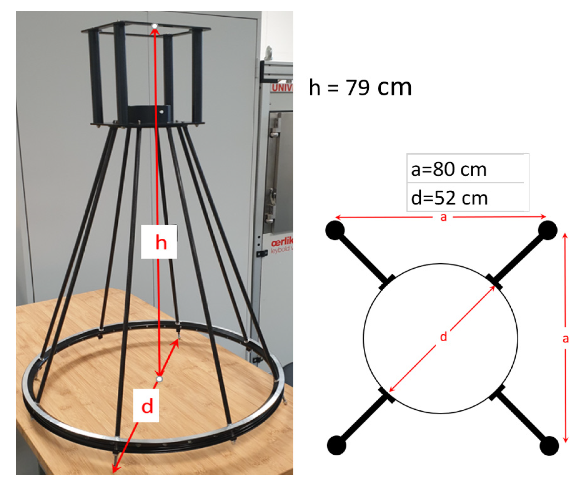
  • The detector’s size makes the drone integration difficult, which means it can only be integrated into medium- and large-sized UASs, with the sensor itself acting as the landing gear. The lens, located at the aircraft’s underbelly, deep below its center of gravity, resists UAS movement. Flight tests conducted in windy conditions revealed significant instabilities in the UAS’s flight. It is not advisable to exchange the landing gear supplied by the manufacturer for incorporating the detector. Therefore, in future iterations, a compact detector design must be implemented.
The major limiting factor of the developed detection system for the localization of point sources is its small field of view. Since the FOV of the detection system (up to 10 cm) is smaller than the uncertainty of the UAS GPS (about a meter), the detection of point sources becomes more difficult. To mitigate this issue, two clear operational improvements are therefore proposed: (i) Equip the UAS with RTK to achieve centimeter-level navigation accuracy. The results show that when the system identifies a point source during different flights, the ground station positions it at nearby locations, but not at the same location. This may be due to the GPS position uncertainties themselves. That is, with the current system, we can affirm that there is alpha activity over that area, but not the exact location and how many point sources there are. With an RTK-ready UAS, the enhanced navigation would allow repeating the same flight plan: this would make passes and identify source positions more consistently and would allow the estimation of the uncertainties related to the source localization. (ii) Increase the FOV of the detector. This would require enlarging the PMT surface, reducing the focal length of the objective, or using mirrors with shorter focal lengths. However, this option would require a tradeoff with background light leakage [17]. An improved FOV would open the possibility of increasing the speed of the UAS and the distance between flight tracks, thus increasing the size of the area scanned with a single flight.
In conclusion, for the first time, a detection system to remotely measure radionuclides emitting alpha particles has been designed, installed on a commercial UAS, and tested in real flights. This developed system opens up the possibility of being used in scenarios that previously posed a high risk for first-response teams.

Author Contributions

Conceptualization, P.R., M.L., A.V., V.D. and F.K.; methodology, P.R., A.V., T.G., D.S., J.P., M.L., V.D. and F.K.; software, P.R., T.G., D.S., J.P. and M.L.; validation, all authors; formal analysis, P.R., A.V., D.R. and M.L.; investigation, all authors; writing—original draft preparation, P.R. and A.V.; writing—review and editing, all authors. All authors have read and agreed to the published version of the manuscript.

Funding

The project 19ENV02 RemoteALPHA has received funding from the European Metrology Programme for Innovation and Research (EMPIR), co-financed by the Participating States and from the European Union’s Horizon 2020 research and innovation program. Funder ID is: 10.13039/100014132.

Data Availability Statement

Data are contained within the article.

Conflicts of Interest

The authors declare no conflicts of interest. The founding sponsors had no role in the design of the study; in the collection, analyses, or interpretation of data; in the writing of the manuscript; or in the decision to publish the results.

References

  1. Gale, R.P.; Armitage, J.O.; Hashmi, S.K. Emergency response to radiological and nuclear accidents and incidents. Br. J. Haematol. 2021, 192, 968–972. [Google Scholar] [CrossRef] [PubMed]
  2. Hogan, D.E.; Kellison, T. Nuclear terrorism. Am. J. Med. Sci. 2002, 323, 341–349. [Google Scholar] [CrossRef] [PubMed]
  3. Royo, P.; Pastor, E.; Macias, M.; Cuadrado, R.; Barrado, C.; Vargas, A. An Unmanned Aircraft System to Detect a Radiological Point Source Using RIMA Software Architecture. Remote Sens. 2018, 10, 1712. [Google Scholar] [CrossRef]
  4. Vargas, A.; Costa, D.; Macias, M.; Royo, P.; Pastor, E.; Luchkov, M.; Neumaier, S.; Stöhlker, U.; Luff, R. Comparison of airborne radiation detectors carried by rotary-wing unmanned aerial systems. Radiat. Meas. 2021, 145, 106595. [Google Scholar] [CrossRef]
  5. Podgorsak, E.B. Radiation Physics for Medical Physicists; Springer: Berlin, Germany, 2006. [Google Scholar]
  6. Burchfield, L.A. Radiation Safety: Protection and Management for Homeland Security and Emergency Response; John Wiley & Sons: Hoboken, NJ, USA, 2009. [Google Scholar]
  7. Crompton, A.J.; Gamage, K.A.A.; Jenkins, A.; Taylor, C.J. Alpha particle detection using alpha-induced air radioluminescence: A review and future prospects for preliminary radiological characterisation for nuclear facilities decommissioning. Sensors 2018, 18, 1015. [Google Scholar] [CrossRef] [PubMed]
  8. Baschenko, S.M. Remote optical detection of alpha particle sources. J. Radiol. Prot. 2004, 24, 75–82. [Google Scholar] [CrossRef] [PubMed]
  9. Sand, J.; Ihantola, S.; Peräjärvi, K.; Toivonen, H.; Toivonen, J. Radioluminiscence yield of alpha particles in air. New J. Phys. 2014, 16, 053022. [Google Scholar] [CrossRef]
  10. Sand, J. Alpha Radiation Detection via Radioluminescence of Air. Ph.D. Thesis, Tampere University of Technology, Tampere, Finland, 2016. Available online: https://trepo.tuni.fi//handle/10024/114881 (accessed on 21 February 2024).
  11. Kerst, T.; Toivonen, J. Intense radioluminescence of NO/N2-mixture in solar blind spectral region. Opt. Express 2018, 26, 33764–33771. [Google Scholar] [CrossRef] [PubMed]
  12. Kerst, T.; Toivonen, J. Dynamic enhancement of nitric oxide radioluminescence with nitrogen purge. Sci. Rep. 2019, 9, 13884. [Google Scholar] [CrossRef] [PubMed]
  13. Krasniqi, F.; Kerst, T.; Leino, M.; Eisheh, J.T.; Toivonen, H.; Röttger, A.; Toivonen, J. Standoff UV-C imaging of alpha particle emitters. Nucl. Instrum. Methods Phys. Res. 2021, 987, 164821. [Google Scholar] [CrossRef]
  14. Remote and Real-Time Optical Detection of Alpha-Emitting Radionuclides in the Environment (RemoteALPHA) Project Official Web-Site. Available online: https://remotealpha.drmr.nipne.ro/ (accessed on 30 August 2023).
  15. Luchkov, M.; Olaru, C.; Lalau, I.; Zadehrafi, M.; Nikolényi, I.R.; Gémesi, Z.; Mihail-Razvan Ioan, M.R.; Krasniqi, F. Radioluminescence mapping of 241Am-doped environmental samples and nuclear materials. J. Radioanal. Nucl. Chem. 2024, 333, 253–262. [Google Scholar] [CrossRef]
  16. Parc Mediterrani de la Tecnologia, DRONELAB Section. Available online: https://pmt.es/ca/dronlab (accessed on 30 August 2023).
  17. Luchkov, M.; Dangendorf, V.; Giesen, U.; Langner, F.; Olaru, C.; Zadehrafi, M.; Klose, A.; Kalmankoski, K.; Sand, J.; Ihantola, S.; et al. Novel optical technologies for emergency preparedness and response: Mapping contaminations with alpha-emitting radionuclides. Nucl. Inst. Meth. 2023, 1047, 167895. [Google Scholar] [CrossRef]
  18. Thorlabs LC4252-UV—Ø1″ Plano-Concave Lens, f = -30.00 mm. Available online: https://www.thorlabs.de/thorproduct.cfm?partnumber=LC4252-UV (accessed on 21 February 2024).
  19. Thorlabs LA4052-UV—f = 35.0 mm, Ø1″ UV Fused Silica Plano-Convex Lens. Available online: https://www.thorlabs.de/thorproduct.cfm?partnumber=LA4052-UV (accessed on 21 February 2024).
  20. Hamamatsu Photonics Web-Site; Photon Counting Head PMT Modules Section. Available online: https://www.hamamatsu.com/us/en/product/optical-sensors/pmt/pmt-module/photon-counting-head/H11870-09.html (accessed on 30 August 2023).
  21. GBS Elektronik GmbH Web Site, Multi-Channel Analyzer Section. Available online: https://www.gbs-elektronik.de/en/nuclear-measurements/multi-channel-analyzer.php (accessed on 30 August 2023).
  22. DJI Matrice 600 Pro. Available online: https://www.dji.com/es/matrice600-pro (accessed on 21 February 2024).
  23. LightWare Lidar LLC Web-Site. Available online: https://lightwarelidar.com/products/sf11-c-100-m (accessed on 30 August 2023).
  24. Raspberry Pi Official Website. Available online: https://www.raspberrypi.com/products/raspberry-pi-4-model-b/ (accessed on 30 August 2023).
  25. Sixfab Official Website. Available online: https://sixfab.com/product/raspberry-pi-4g-lte-modem-kit/ (accessed on 30 August 2023).
  26. Be, M.M.; Chiste, V.; Dulieu, C.; Mougeot, X.; Browne, E.; Chechev, V.; Kuzmenko, N.; Kondev, F.; Luca, A.; Galan, M.; et al. Table of Radionuclides (Vol. 5—A = 22 to 244); Bureau International des Poids et Mesures: Sevres, France, 2010; ISBN 13 978-92-822-2234-8. [Google Scholar]
  27. MQTT Official Website. Available online: https://mqtt.org/ (accessed on 31 August 2023).
  28. RabbitMQ Official Website. Available online: https://www.rabbitmq.com/ (accessed on 31 August 2023).
  29. European Accreditation. EA-4/02 M: 2013 Evaluation of the Uncertainty of Measurement in Calibration. 2013, p. 75. Available online: https://www.twirpx.com/file/1996254/ (accessed on 21 February 2024).
  30. ISO 11929-4:2022; Determination of the Characteristic Limits (Decision Threshold, Detection Limit and Limits of the Coverage Interval) for Measurements of Ionizing Radiation. ISO: Geneva, Switzerland, 2022. Available online: https://www.iso.org/standard/84497.html/ (accessed on 21 February 2024).
Figure 1. The optical system detector developed for the measurement of alpha particles during unmanned aircraft flights is mainly composed of a Fresnel lens, a photomultiplier tube (PMT) detector, and a multichannel analyzer (MCA) counter.
Remotesensing 16 00848 g001
Figure 2. The previously calibrated UV-C LED lamp used during laboratory tests to simulate alpha sources with an energy of about 5.4 MeV and activities up to 7.3 GBq using a power adjustment of level 11. A small Teflon plate was installed to diffuse and attenuate the beam.
Remotesensing 16 00848 g002
Figure 3. Graphical representation of the configuration used for the laboratory tests. The UV-C LED lamp was in a fixed position, where the optical system could move to different distances from the light source.
Remotesensing 16 00848 g003
Figure 4. Left side: The structure of the optical system that shows the total height (h) and bottom circle diameter (d). Right side: A scheme of the landing legs installed at the bottom of the structure.
Remotesensing 16 00848 g004
Figure 5. Pictures of the two unmanned aircraft systems evaluated to be used for the mounting of the optical system to remotely detect alpha particles. The DJI Matrice 600 Pro was finally used in this study.
Remotesensing 16 00848 g005
Figure 6. (Left panel) Cellular modem coupled to the onboard computer installed on the drone (Image source: https://docs.sixfab.com/docs/raspberry-pi-4g-lte-cellular-modem-kit-getting-started (accessed on 21 February 2024). (Right panel) Picture of the onboard computer and its different components.
Remotesensing 16 00848 g006
Figure 7. Image of a field experiment with the optical detection system already integrated within the unmanned aircraft DJI Matrice 600 Pro.
Remotesensing 16 00848 g007
Figure 8. Picture of the five UV-C LEDs designed and fabricated to create light sources during the field flight experiments. On the top of each UV-C LED were located several Teflon sheets to attenuate the beams.
Remotesensing 16 00848 g008
Figure 9. A schematic of a cross-sectional view of the americium source implanted on the surface of a rectangular aluminum plate (red line) and the quartz glass chamber containing it.
Remotesensing 16 00848 g009
Figure 10. (Left panel) Picture of the quartz glass chamber containing the 241Am source in a field experiment during the insertion of N2 + NO (50 ppm) gas into the chamber volume. (Right panel) Plot of the counts observed during tens of seconds by the optical system during a flight experiment without the 241Am source (blue circles), with the 241Am source (orange circles), and with 241Am source plus N2 + NO (50 ppm) gas within the chamber volume (gray circles).
Remotesensing 16 00848 g010
Figure 11. A block schematic of the software architecture used for the recording and sending of the data during the flights and the communication between the drone and the ground station. The software architecture is mainly divided into aerial (upper panel) and ground (bottom panel) segments.
Remotesensing 16 00848 g011
Figure 12. Details of the ground control segment of the software architecture used to obtain the data from the aerial segment and visualize it in real time during the flights. The recorded count rate is placed over the map with different colors in relation to the count rate increase.
Remotesensing 16 00848 g012
Figure 13. A screenshot of the ground station visualization available during flights by using the developed web application.
Remotesensing 16 00848 g013
Figure 14. A screenshot of the ground control station visualization during a test flight. The recorded count rates are displayed over the map with different colors in relation to the count rates increase (example: yellow = background count rates; red = high count rates).
Remotesensing 16 00848 g014
Figure 15. A plot of the light counts recorded during the laboratory test as a function of the focal lens distance (F) and for each light source distance (d). Red circles indicate the maximum number of counts obtained for each distance. Uncertainties in the figure correspond to standard deviations given with a 68% confidence interval (k = 1) and are attributed to the counting statistics of the detection system.
Remotesensing 16 00848 g015
Figure 16. A plot of the light counts measured during the laboratory test at different source–detector distances (d) and for different lateral positions (h) of the source. F represents the focal lens distance.
Remotesensing 16 00848 g016
Figure 17. A plot of the detector efficiency against the distance (d) between the light source and the detector for a focal length F = 3 (blue cycles) and for F = the maximum obtained from Figure 15 results (F = 3, 4, and 7, in orange stars).
Remotesensing 16 00848 g017
Figure 18. Schematics of scan patterns that can be generated by the ground control station during flights.
Remotesensing 16 00848 g018
Figure 19. Examples of one (left panel) or two (right panel) iterations of the unmanned aircraft systems flight plan, where the yellow cylinders represent the count rate measured during the drone flight (example: yellow = background counts).
Remotesensing 16 00848 g019
Figure 20. Images of the unmanned aircraft system’s flight plan for a real plan (left panel) and a simulated flight (right panel), where the yellow cylinders represent the count rate measured on the drone’s path.
Remotesensing 16 00848 g020
Figure 21. A picture of a typical configuration used for test flights carried out at the DroneLab of the Technical University of Catalonia. The five LED sources are the black cylinders located on the soil.
Remotesensing 16 00848 g021
Figure 22. (Upper panel): Picture of the field flight carried out with the new optical system. The five LED sources and the americium source are located on the soil surface. (Bottom panel): An image of the unmanned aircraft system’s ground control station for a real plan carried out using the 5 LEDs and an americium source. The image displays the count rate in various colors, according to the increase in counts (example: yellow = background count rate; red = high count rate).
Remotesensing 16 00848 g022
Table 1. Weight estimation of each component of the unmanned aircraft system’s payload.
ComponentsWeight (g)
Detector structure and landing gear2591
PMT detector408
GBS MCA527OEM + onboard computer +
air–ground communications and wires
468
TOTAL3467
Table 2. The fields of view and angular fields of view estimated for different F positions and source–lens distances.
F (cm)d (m)n (s−1)FOV (cm)AFOV (°)
3222409.62.75
3325107.51.44
3 *415508.61.24
3 *581110.71.22
7 *260704.11.17
4 *327706.41.23
* Indicates the case for F of the maximum measured count rate.
Table 3. The estimation of the detection efficiency in the case of an extended source with a maximum field of view focus configuration of F = 3 cm.
F (cm)d (m)n (s−1)FOV (cm)AFOV (°)ε (s−1 MBq−1)εs (s−1 MBq−1 cm2)
3222409.62.750.3122
3325107.51.440.3415
3415508.61.240.2112
3581110.71.220.1110
Table 4. The estimation of the detection efficiency in the case of an extended source with a maximum count rate focus configuration.
F (cm)d (m)n (s−1)FOV (cm)AFOV (°)ε (s−1 MBq−1)εs (s−1 MBq−1 cm2)
7260704.11.170.8311
4327706.41.230.3812
3415508.61.240.2112
3581110.71.220.1110
Disclaimer/Publisher’s Note: The statements, opinions and data contained in all publications are solely those of the individual author(s) and contributor(s) and not of MDPI and/or the editor(s). MDPI and/or the editor(s) disclaim responsibility for any injury to people or property resulting from any ideas, methods, instructions or products referred to in the content.

