Abstract
An enhanced Doppler resolution and sidelobe suppression have long been practical issues for moving target detection using Golay complementary waveforms. In this paper, Golay complementary waveform radar returns are combined with a proposed processor, the pointwise thresholding processor (PTP). Compared to the pointwise minimization processor (PMP) illustrated in a previous work, which could only achieve a Doppler resolution comparable to existing methods, this approach essentially increases the Doppler resolution to a very high level in theory. This study also introduced a further filtering process for the delay-Doppler map of the PTP, and simulations verified that the method results in a delay-Doppler map virtually free of range sidelobes.
1. Introduction
Due to complementarity, Golay complementary waveforms are effective at producing a satisfactory resolution range in a delay-Doppler map, as well as theoretical free-range side lobes at zero Doppler. Nevertheless, obvious range sidelobes are induced in nonzero Doppler intervals by their sensitivity to Doppler mismatch during matched filtering, and it is hard for conventional sidelobe suppression methods such as windowing to eliminate them.
A decade ago, Calderbank and Pezeshki et al. addressed the above problem by carefully designing Golay complementary waveforms in a specific transmitted order, named the Prouhet–Thue–Morse (PTM) design, which caused a satisfactory reduction in the range sidelobes in a narrow band around zero Doppler in the delay-Doppler map [1,2]. In a similar way, Suvorova et al. extended the idea of transmitted order design from the PTM sequence to the Reed–Müller codes, achieving a minimum range sidelobe level at a given Doppler bin in the delay-Doppler map [3]. This was further studied by Dang et al., who presented a binomial design (BD) algorithm that assigns weights to the matched filtering sequence of Golay complementary waveforms and significantly expands the sidelobe blanking area at the cost of an obvious decrease in the Doppler resolution [4]. Based on these works, Wu et al. employed semidefinite programming as a novel method to design complementary waveforms for improved sidelobe suppression as well as Doppler resolution [5,6].
However, the aforementioned methods only either preserve the Doppler resolution (none of them exceed the resolution of the conventional Golay pair) or enlarge the sidelobe blanking area, but they cannot achieve both at the same time. From another view, pointwise processing [7] (or cell-by-cell processing in some publications [8,9]) has been extensively researched in the processing of radar images to integrate the advantages of two figures and produce a further improvement in the signal-to-noise ratio (SNR). In our early work [10], a pointwise minimization processor (PMP) was proposed to combine the delay-Doppler maps of the BD algorithm with a weighted average Doppler (WD) algorithm under Golay waveforms, which maintained the Doppler resolution as well as a large sidelobe suppression area. However, as described before, the results of the PMP cannot exceed the original Doppler resolution of the waveform. Therefore, another designed pointwise thresholding processor (PTP) is proposed in this research to replace the PMP, which can further increase the Doppler resolution. A further filtering process is then applied based on the delay-Doppler map of the PTP, which almost eliminates the range sidelobes.
In the remainder of the manuscript, a brief introduction to Golay pairs and PMP is first given in Section 2, then the PTP is introduced. Section 3 presents the simulation results of the PMP and the PTP and compares the performance under fixed and randomized scenarios. The delay-Doppler map of a further filtering process after the PTP is also simulated to illustrate the improved sidelobe suppression performance. The conclusion and future directions are discussed in Section 4.
2. Golay Complementary Waveforms and Pointwise Processors
2.1. Golay Pairs
A Golay pair (complementary waveforms) consists of two length L sequences, and , with several unimodular () values/chips in each sequence [11]. The time width of each pair is ( for each chip). This waveform scheme is well known for its complementarity, i.e., the autocorrelation of the sequence pair is
where and are the autocorrelation outputs of and at lag k, respectively, and is the Kronecker delta function.
The sequence pair cannot be transmitted in the time domain before modulating a baseband pulse with unit energy on each chip, which means the transmitted sequences are given as
where
Next, the transmission of either or is determined by a pulse train. Here, is a binary sequence and the transmitted pulses are presented as
where denotes the standard transmission order and T represents the pulse repetition interval (PRI). On the other hand, stands for the positive real number weights on the radar returns, where an all 1 sequence is the standard weighting. Next, the signal for matched filtering is written as
Specifically, the BD algorithm [4] designs Q as a binomial sequence, i.e., .
According to [12], we then calculate the delay-Doppler map of Golay complementary waveforms as follows:
where “*” denotes the complex conjugation.
The first item contains , which is an impulse function due to the complementarity; thus, the sidelobe in the delay-Doppler map is only influenced by the second item.
For transmission order design methods such as standard order and PTM design, is always 1; thus, the sub-item
reaches 0 at , which means it is free of a sidelobe along the -Doppler axes and the Doppler resolution of the target is . However, a significant sidelobe can be observed at other Doppler axes other than . Moreover, for the PTM, it is easy to calculate that is negligible if is small.
For receiving weight design methods, i.e., the BD algorithm, alternates between 1 and 0, while is the coefficient of the binomial. Then, the sub-item is further expressed as
Obviously, the expression does not have zero points (which means the Doppler resolution is poor), while the value is an exponential function and its absolute value exponentially increases as increases. This is the reason why a large sidelobe blanking area is generated.
The delay-Doppler maps of previous works are plotted in Figure 1 for a better understanding. As is demonstrated, the delay-Doppler maps of standard order and PTM design are divided into “grids” by the zero points, while the BD algorithm obtains a large blanking area with an exponential-like sidelobe on the side. The delay resolutions of the aforementioned approaches are all , which is the width of the impulse function.

Figure 1.
Delay-Doppler maps: (a) standard order; (b) PTM design; (c) BD algorithm (the unit of the colorbar is dB, ).
2.2. Pointwise Minimization Procedure
Figure 2 describes the procedure presented in our early work [10], where , and , respectively, stand for the delay-Doppler maps of the BD algorithm, the WD algorithm and this procedure. Specifically the “Pointwise Processor” in [10], represents the pointwise minimization processor (PMP), whose result is denoted as .

Figure 2.
Demonstration of the procedure: pointwise processor PMP or PTP.
The WD algorithm is demonstrated based on [3] to select the the optimal transmission order of Golay complementary waveforms (a standard weighted Q is set for this algorithm), which minimizes the sidelobes near a known Doppler value. Here, we employ the mean target Doppler associated with their amplitudes to bring the sidelobe blanking area closer to the weak targets [13]:
where and are the normalized amplitude and Doppler of the target, respectively, and H is the number of targets in the delay-Doppler map. A tracker is usually used to estimate the target magnitude and Doppler from the past detections [14].
Already existing methods, such as [1,2,3,4], etc., are able to suppress the range sidelobes and improve the signal-to-noise ratio (SNR) near the targets to different extents. However, they cannot reduce the overall sidelobe magnitude in the underlying surveillance window. Therefore, a PMP was proposed in our previous paper as a nonlinear pointwise processor, which achieves sidelobe suppression involving sidelobe power reduction and does not cause target loss, as verified by technical simulations.
The advantage of the PMP is that it maintains the ideal large range sidelobe blanking region (in which the range sidelobes are less than ) provided by the BD algorithm and the acceptable Doppler resolution of the WD algorithm, based on the assumption that the targets are stable during the whole radar illumination. As described before, a drawback of the PMP is that it can only retain the improved Doppler resolution and the lower sidelobes of the two approaches. It still needs further enhancement when the Doppler resolution and sidelobe suppression performance fail to meet the requirements; thus, we propose the PTP in the following.
2.3. Pointwise Thresholding Procedure
The “Pointwise Processor” in Figure 2 is defined as the pointwise thresholding processor (PTP) and is defined as the output of the PTP. Then, the processor is expressed as
where the threshold is artificially delimited considering the magnitude difference of targets and sidelobes. As the most important parameter in the processor, it directly influences the sidelobe level and the resolution (and also the performance of further filtering that will be discussed later). A small value will have no effect on the enhancement in Doppler resolution and sidelobe blanking performance, while a too large threshold may also blank the targets. Obviously 0 dB, and we commonly consider it nonsensical if > 10 dB, since the radar return fluctuation of two illuminations caused by target micro-motion and other interferences normally cannot reach such a high level. In this paper, we choose = 2 dB as an example [15], but further research needs to be performed for better determination of the practical threshold. Under the same assumption, the PTP is expected to bring a further increase in the Doppler resolution and suppress the sidelobe magnitude compared to the PMP, which will be illustrated by the simulations in the next section.
3. Simulation and Further Discussion
The PTP is verified in simulations with the following global parameters when no other demonstration is presented. The targets in the simulations are set as Swerling II targets with fluctuation in the radar cross-section (RCS).
- , carrier frequency: 1 GHz;
- B, bandwidth: 50 MHz;
- , time sampling rate: 2 B;
- , Doppler sampling rate: 0.01 rad;
- T, PRI: 50 μs;
- N, pulse number: 32;
- L, chip number of Golay pair: 64;
- , chip interval: 0.1 μs;
- E∼, complex Gaussian zero-mean white noise: −10 dB (i.e., = 10 dB).
3.1. Fixed Scenario
We first consider a fixed scenario with three targets (one weak and two strong targets), whose ground truth locations and magnitudes are listed in Table 1 and shown in Figure 3. Note that two strong targets can only be separated from the Doppler.

Table 1.
Simulated target locations in the fixed scenario.
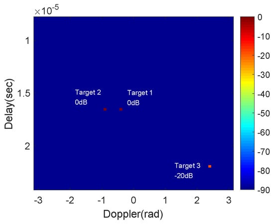
Figure 3.
The ground truth locations and magnitudes of targets.
The delay-Doppler maps of the BD and WD algorithms and the outputs of the PMP and PTP with = 2 dB are given in Figure 4, and the comparison results of PMP and PTP in terms of the delay cross-section and Doppler cross-section, respectively, at all the targets location are then illustrated in Figure 5 and Figure 6. Obviously, though PMP maintains the Doppler resolution of the WD algorithm, it performs much worse than the PTP. In addition, the overall SNR of the PTP in theory is also remarkably higher than the PMP (which may result in a higher performance during target detection). However, the processing times of the PMP and PTP will be twice those of separately using the BD or WD algorithm.
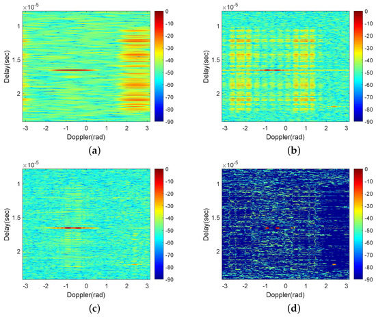
Figure 4.
The results (in dB) of (a) the BD algorithm; (b) the WD algorithm; (c) the PMP; (d) the PTP.

Figure 5.
The delay cross-section of (a) target 1; (b) target 2; (c) target 3 using the PMP and PTP.
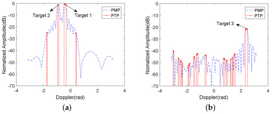
Figure 6.
The Doppler cross-section of (a) target 1 and target 2 and (b) target 3 using the PMP and PTP.
The PTP results at different thresholds are also compared in Figure 7. When = 1 dB, the weak target is nearly blanked by the PTP, while two false targets near the strong targets may be detected if is increased to 8 dB. This further verified the previous illustration of the thresholding.
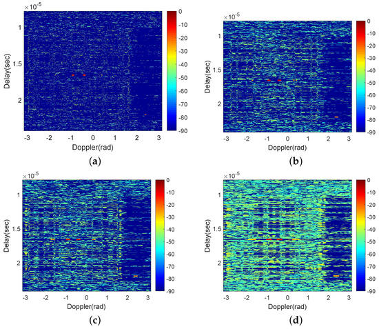
Figure 7.
Delay-Doppler maps of the PTP when (a) = 1 dB; (b) = 2 dB; (c) = 4 dB; (d) = 8 dB (the unit of the colorbar is dB).
3.2. Further Filtering for the PTP
Even though we have discussed the better target detection ability of the PTP than PMP, the targets are still not easily visually detected. Therefore, a further filtering for PTP is proposed in this subsection, which picks the targets through its displayed characters in the map and almost eliminates the range sidelobes after filtering.
According to the delay-Doppler maps we obtain, it is found that the targets are displayed typically (approximate to a rectangle, whose size is related to the threshold as well as the pulse number N) in the results of the PTP, whereas the range sidelobes are usually irregular and cannot be described by the common shape. This character gives us a chance to further filter the targets and suppress the sidelobes in the images. A particular rectangle with a similar size to the target can be employed to search the delay-Doppler map after the PTP, and the target is considered to be found when all the values in the rectangle are higher than (since the original effect of the PTP suppresses some of the range sidelobes lower than ). Note that the size of the target should be evaluated first before the above operation.
Based on the previous illustration in [13] and our subsequent analysis, we learned that the delay resolution of the target after PTP mainly depends on the threshold , while the Doppler resolution is primarily influenced by the pulse number N. On the other hand, the original delay and Doppler resolution of target can be analytically calculated as and , as described in Section 2.1, which means they occupy 20 and 19 pixels in the delay and Doppler axes, respectively. Though it is still hard to analytically calculate the size of this particular rectangle, which is expressed as the number of pixels occupied in the row (delay axis, ) and column (Doppler axis, ) of the delay-Doppler map, a numerical fitting could be adopted to obtain an experimental Equation (13) with a certain calculable basis to illustrate the and of the rectangle. By observing Figure 4 and Figure 7, we find that the delay and Doppler pixels of the target both shrink by about a half after the PTP, while the number of delay pixels needs to be further increased, which is nearly equal to the value of . Therefore, the experimental Equation (13) is written as follows, where the operator “round” means calculating to the nearest integer.
This experimental equation is only used for an explanation of the filtering process that is handled in this work. A more careful deduction of the calculation of this rectangle in practical studies will be the next step of our research.
The outputs of further filtering of the PTP at different thresholds and pulse numbers are demonstrated in Figure 8, which exhibit that further filtering makes the delay-Doppler map almost free of range sidelobes and the targets can be clearly visually recognized. Nevertheless, the lower threshold may lead to a higher probability of miss detection (Target 3 is lost under ), and the increase in pulse number may generate more false targets (some false targets arise when ).


Figure 8.
The outputs of further filtering of the PTP when (a) , ; (b) , ; (c) , ; (d) , ; (e) , ; (f) , ; (g) , ; (h) , (the unit of the colorbar is dB).
3.3. Randomized Scenario
In this scenario, several cases of Swerling II targets with different numbers are uniformly distributed in the delay-Doppler map. Based on the previous global parameters, we consider the following four cases:
- (1)
- Target number: 2 (one strong and one weak);
- (2)
- Target number: 3 (one strong and two weak);
- (3)
- Target number: 4 (two strong and two weak);
- (4)
- Target number: 5 (three strong and two weak).
and N are fixed as and 32, respectively, in all cases.
For the sake of a clearer explanation, the target detection thresholds in these cases are set to the magnitude of the weakest target, which means that all the targets can be detected but false targets may also exist in the range sidelobes. Again, the proper setting of realistic detection thresholds requires further consideration.
A Monte Carlo simulation was operated for 1000 iterations for each case above, and the number of correct detections was calculated. A correct detection is counted when targets are all detected without any false targets. The correct detection occurrences of the PMP, the PTP and the PTP after further filtering are shown in Figure 9.
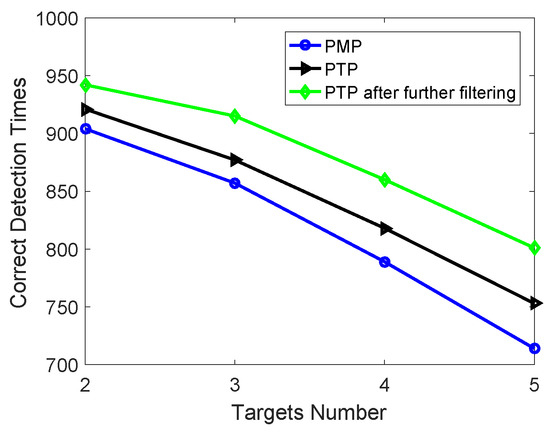
Figure 9.
Correct detection occurrences of the PMP, the PTP and the PTP after further filtering.
As is observed, the PTP provided in this paper outperforms the previous proposed PMP due to a higher overall SNR, as discussed before. The output of the PTP after further filtering has even more correct detection occurrences than the others since the improved range sidelobe effect is achieved.
4. Conclusions
In this paper, a signal processing method involving a PTP is proposed for Golay complementary waveforms to achieve an essentially enhanced Doppler resolution compared to the previously proposed PMP, which can only maintain the original Doppler resolution of this waveform scheme. To solve the visual recognition problem of targets in a delay-Doppler map, further filtering of the PTP by extracting the targets more precisely through a particular rectangle is also employed for a significant improvement in range sidelobe suppression. The performance of the above methods are verified by simulation results. Our future research avenues may concern practical experiments of adaptive thresholding (such as constant false alarm rate, CFAR) and target detection under this waveform scheme, as well as some robust waveform optimization methods for complex target detection [16,17].
Author Contributions
Conceptualization and supervision, X.H.; methodology, J.Z. and Y.S.; software validation, J.Z., N.J. and Z.X.; writing—original draft preparation J.Z.; writing—review and editing, N.J., Z.X. and C.F.; funding acquisition, J.Z. All authors have read and agree to the published version of the manuscript.
Funding
This work was partly supported by the National Natural Science Foundation of China under grant 62101573 and the scientific research project of National University of Defense Technology under grant ZK20-35.
Data Availability Statement
Not applicable.
Acknowledgments
The authors would like to thank Bill Moran and Xuezhi Wang from the University of Melbourne and RMIT University for discussions on this work, and would also like to thank the editors and reviewers for their valuable suggestions for the improvement in this manuscript.
Conflicts of Interest
The authors declare no conflict of interest.
References
- Pezeshki, A.; Calderbank, A.R.; Moran, W.; Howard, S.D. Doppler resilient Golay complementary waveforms. IEEE Trans. Inform. Theory 2008, 54, 4254–4266. [Google Scholar] [CrossRef]
- Calderbank, R.; Howard, S.; Moran, B. Waveform diversity in radar signal processing. IEEE Signal Process. Mag. 2009, 26, 32–41. [Google Scholar] [CrossRef]
- Suvorova, S.; Howard, S.; Moran, B.; Calderbank, R.; Pezeshki, A. Doppler resilience, Reed-Muller codes and complementary waveforms. In Proceedings of the 2007 Conference Record of the Forty-First Asilomar Conference on Signals, Systems and Computers, Pacific Grove, CA, USA, 4–7 November 2007; pp. 1839–1843. [Google Scholar]
- Dang, W.; Pezeshki, A.; Howard, S.; Moran, W.; Calderbank, R. Coordinating complementary waveforms for sidelobe suppression. In Proceedings of the 2011 Conference Record of the Forty Fifth Asilomar Conference on Signals, Systems and Computers (ASILOMAR), Pacific Grove, CA, USA, 6–9 November 2011; pp. 2096–2100. [Google Scholar]
- Wu, Z.; Wang, C.; Jiang, P.; Zhuo, Z. Range-Doppler sidelobe suppression for pulsed radar based on Golay complementary codes. IEEE Signal Process. Lett. 2020, 27, 1205–1209. [Google Scholar] [CrossRef]
- Wu, Z.; Wang, C.; Jiang, P.; Zhuo, Z. Doppler resilient complementary waveform design for active sensing. IEEE Sen. J. 2020, 20, 9963–9976. [Google Scholar] [CrossRef]
- Zhu, J.; Song, Y.; Fan, C.; Huang, X. Nonlinear processing for enhanced delay-Doppler resolution of multiple targets based on an improved radar waveform. Signal Process. 2017, 130, 355–364. [Google Scholar] [CrossRef]
- Richards, M.A.; Scheer, J.A.; Holm, W.A. Principles of Modern Radar Volume I-Basic Principles; Scitech Publishing: Raleigh, NC, USA, 2010. [Google Scholar]
- Ciuonzo, D. On time-reversal imaging by statistical testing. IEEE Signal Process. Lett. 2017, 24, 1024–1028. [Google Scholar] [CrossRef]
- Zhu, J.; Wang, X.; Huang, X.; Suvorova, S.; Moran, B. Range sidelobe suppression for using Golay complementary waveforms in multiple moving target detection. Signal Process. 2017, 141, 28–31. [Google Scholar] [CrossRef]
- Golay, M. Complementary series. IRE Trans. Inform. Theory 1961, 7, 82–87. [Google Scholar] [CrossRef]
- Richards, M.A. Fundamentals of Radar Signal Processing; McGraw-Hill Education: New York, NY, USA, 2005. [Google Scholar]
- Zhu, J.; Wang, X.; Huang, X.; Suvorova, S.; Moran, B. Golay Complementary Waveforms in Reed-Müller Sequences for Radar Detection of Nonzero Doppler Targets. Sensors 2018, 18, 192. [Google Scholar] [CrossRef] [PubMed]
- Dang, W. Signal Design for Active Sensing. Ph.D. Dissertation, Colorado State University, Fort Collins, CO, USA, 2014. [Google Scholar]
- Rasool, S.B.; Bell, M.R. Biologically inspired processing of radar waveforms for enhanced delay-Doppler resolution. IEEE Trans. Signal Process. 2011, 59, 2698–2709. [Google Scholar] [CrossRef]
- Xie, Z.; Fan, C.; Xu, Z.; Zhu, J.; Huang, X. Robust joint code-filter design under uncertain target interpulse fluctuation. Signal Process. 2022, 201, 108687. [Google Scholar] [CrossRef]
- Xie, Z.; Xu, Z.; Fan, C.; Han, S.; Huang, X. Robust radar waveform optimization under target interpulse fluctuation and practical constraints via sequential lagrange dual approximation. IEEE Trans. Aero. Electron. Syst. 2023; accepted for publication. [Google Scholar] [CrossRef]
Disclaimer/Publisher’s Note: The statements, opinions and data contained in all publications are solely those of the individual author(s) and contributor(s) and not of MDPI and/or the editor(s). MDPI and/or the editor(s) disclaim responsibility for any injury to people or property resulting from any ideas, methods, instructions or products referred to in the content. |
© 2023 by the authors. Licensee MDPI, Basel, Switzerland. This article is an open access article distributed under the terms and conditions of the Creative Commons Attribution (CC BY) license (https://creativecommons.org/licenses/by/4.0/).