Abstract
This paper analyzes the possibility of maintaining a circular displaced non-Keplerian orbit around the Sun by means of a Sun-facing diffractive sail. With the goal of monitoring the Earth’s high-latitude regions, the spacecraft is required to track its displaced orbit at an angular velocity equal to the mean motion of the planet. In doing so, the spacecraft keeps a constant average phase shift with respect to Earth’s angular position along its orbit, allowing the objectives of the scientific mission to be achieved. The diffractive sail, recently proposed by Swartzlander and chosen in this paper as the spacecraft’s primary propulsion system, is a special photonic solar sail in which the membrane film is covered by an advanced diffractive metamaterial. In particular, a Sun-facing diffractive sail with a grating at normal incidence generates radial and transverse thrust components of equal magnitude; that is, the thrust vector is tilted 45 degrees from the Sun-spacecraft line. This peculiarity enables the diffractive sail to maintain a family of circular displaced non-Keplerian orbits, each of which is characterized by unique values of radius and a lightness number for an assigned value of spacecraft displacement relative to the Ecliptic. A comparison with the ideal reflecting sail shows that the diffractive sail performs better because for the same overall spacecraft mass, the latter needs about less surface area exposed to the Sun. Finally, this paper discusses the classical stability problem, assuming an error in orbit insertion of the diffractive sail-based spacecraft. In this context, extensive numerical simulations show that such displaced orbits are marginally stable.
1. Introduction
Solar radiation pressure is the basis of the operating principle of photonic solar sails, a class of propellantless propulsion systems that convert solar radiation pressure into thrust []. Among them, the now well-known reflecting solar sails [,] reflect photons thanks to a membrane coated with a highly reflective material. In addition to reflection, other optical phenomena, such as refraction or diffraction [,,], have been studied in recent years to enable momentum transfer between photons from the Sun and the sail-based spacecraft. In particular, a refractive sail generates thrust by deflecting incoming photons through the refraction of sunlight across a thin transparent membrane made of polymeric micro-prisms [,,], while a diffractive sail uses a metamaterial film to diffract incoming photons and deflect them from their natural path [,,]; see Figure 1, which shows a conceptual sketch of a translucent diffractive sail in a low-Earth orbit.
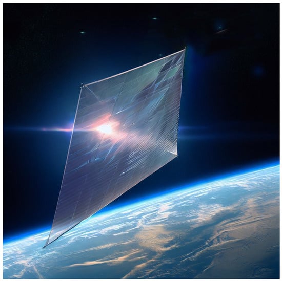
Figure 1.
Conceptual sketch of a diffractive sail in a low-Earth orbit. Digital picture generated with the aid of Bing Image Creator.
In this context, the pioneering work of Swartzlander [] showed that the performance of a sort of translucent diffractive sail is superior (in terms of the required flight time) to a Littrow diffraction configuration or to a more conventional reflecting sail when the spacecraft attitude is constant relative to an orbital reference frame. In particular, Swartzlander [] also determined that a diffraction film with a grating period of one micrometer can convert about of the solar spectrum into spacecraft momentum and described the advantages of diffractive sails by comparing suboptimal orbit-raising trajectories for diffractive and reflecting solar sails. In this context, Dubill and Swartzlander [] proposed exploiting a diffractive sail to increase the orbital inclination and reduce the orbital radius of a spacecraft in a typical interplanetary mission scenario. More recently, building on the above interesting results [,], the authors [,] have analyzed the performance of a Sun-facing diffractive sail in the context of minimum-time interplanetary trajectories. Many other literature works [,,,,] demonstrate the growing interest of scientists in the diffractive sail concept.
According to the recent literature [,], unlike reflecting solar sails, the great advantage of refractive and diffractive sails is that they can generate a large transverse component of thrust, even when facing the Sun, such as when their nominal plane is perpendicular to the Sun–spacecraft line. Bearing in mind this peculiarity, the aim of this work is to study the maintenance of circular displaced non-Keplerian orbits (DNKOs) by means of a Sun-facing diffractive solar sail. Recall that a DNKO does not contain the center of mass of the primary body [], and therefore, although it can be approximated with a sequence of Keplerian arcs connected through impulsive maneuvers [,], it requires the application of a continuous thrust to be maintained. For this reason, the use of propellantless propulsion systems, such as solar sails, is attractive because of the opportunity they offer to achieve long-duration missions. In fact, the most common alternative for orbit maintenance, which is the use of electric propulsion, would limit the duration of the mission and its scientific return based on complete propellant consumption [,].
Maintaining a DNKO is of particular interest for monitoring high-latitude terrestrial regions and is an effective option for many other applications, as extensively discussed in the useful survey paper by McKay et al. []. That is why there are so many articles dealing with the problem of maintaining DNKOs by means of propellantless propulsion systems. For example, McInnes and Bookless [] have proposed using a solar sail to generate families of displaced periodic orbits at planetary bodies, Gong et al. [,] studied the possibility of maintaining elliptic DNKOs by means of solar sails for planetary polar observation and investigated the relative orbit design and control methods for formation flight around displaced solar orbits, while Song et al. [] analyzed solar sail displaced orbits in Hill’s restricted three-body problem. More recently, Bassetto et al. [] studied the performance of the magnetic sail conceived by Robert Zubrin [,,] in maintaining circular DNKOs.
In this paper, a Sun-facing diffractive sail is required to trace a circular DNKO at an angular velocity equal to the mean motion of the Earth [] so as to maintain a constant average phase shift with respect to the angular position of our planet along its heliocentric orbit. The characteristics of the thrust vector of a Sun-facing diffractive sail enable the maintenance of a family of circular displaced non-Keplerian orbits, each of which is characterized by unique values of radius and a lightness number for an assigned value of the elevation angle (i.e., the angle between the Sun–spacecraft line and the Ecliptic), the latter being a design parameter. A comparison with the (ideal) reflecting solar sail option shows that, for the family of feasible displaced orbits considered in this study, the diffractive sail performs better than the more classical reflecting sail. In particular, a case study shows that circular DNKOs based on diffractive sails are marginally stable.
This paper is organized as follows. Section 2 describes a simplified version of the diffractive sail thrust model by using the recent literature results. Section 3 analyzes the characteristics of feasible DNKOs and the performance required by the diffractive sail. In addition, Section 3 provides the distance of the spacecraft from Earth as a function of a set of design parameters, a comparison with the reflecting sail case, and the characteristics of the spacecraft osculating orbit. Section 4 deals with linear stability analysis of the orbit and shows the results of a numerical simulation chosen as an example. Finally, Section 5 contains our concluding remarks.
2. Simplified Diffractive Sail Thrust Model in Sun-Facing Condition
This section summarizes a simplified version of the more general (and refined) thrust model proposed by Swartzlander [], which has been recently used by the authors [,] to analyze the performance in a typical interplanetary mission scenario. In fact, similar to more classical reflecting solar sails [,], the propulsive acceleration vector provided by a diffractive sail depends on the attitude of the sail reference plane relative to the Sun. In this context, an early mathematical model useful to describe the thrust vector characteristics of a diffractive sail as a function of the spacecraft attitude was proposed about six years ago in fundamental work []. A few years later, Dubill and Swartzlander [] specialized that first model to the case of a Sun-facing attitude, which is precisely the case analyzed in this paper.
First of all, we introduce a right-handed body frame , where C coincides with the spacecraft center of mass, while the direction of the three axes is described by the unit vectors , respectively. The reference frame is sketched in Figure 2, which has been adapted from [].
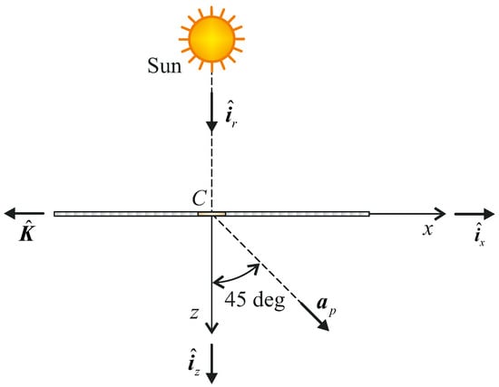
Figure 2.
Diffractive sail of center of mass C facing the Sun, propulsive acceleration vector , grating momentum unit vector , and right-handed body reference frame of unit vectors .
In particular, the plane identifies the nominal plane of the (flat) diffractive sail, and the x-axis direction is opposite to the grating momentum unit vector (i.e., in the figure), which is in turn, aligned with the direction of periodicity of the grating []. Note also that, according to Dubill and Swartzlander [], a Sun-facing diffractive sail with a grating at normal incidence generates radial and transverse thrust components of equal magnitude: that is, the propulsive acceleration vector is tilted 45 degrees with respect to the Sun–spacecraft unit vector , as sketched in Figure 2.
Consequently, when the z-axis is aligned with the Sun–spacecraft line (i.e., when ), the propulsive acceleration vector can be written in a compact form as
where r is the Sun–spacecraft distance, S is the surface area of the sail, c is the speed of light in vacuum, m is the total mass of the spacecraft (which is assumed to be constant), and is the solar constant; that is, the solar irradiance at the reference distance from the Sun. Equation (1) can be rewritten in a more elegant form by introducing the characteristic acceleration [], defined as the maximum value of when . Taking Equation (1) into account, the expression of the characteristic acceleration is then given by
from which one obtains the propulsive acceleration vector as a function of , viz.
where
is the lightness number, that is, a dimensionless form of , being , the Sun’s gravitational parameter.
3. Maintenance of Circular DNKOs
The thrust vector model of a (flat) diffractive sail, described in the previous section, is used here to study the possibility of maintaining circular DNKOs []. With reference to the scheme in Figure 3, we introduce a perifocal reference system , where O is the center of mass of the Sun, the p-axis is aligned with the eccentricity vector of the Earth (omitted in the figure for simplicity), and the w-axis is parallel to the angular momentum of the Earth’s heliocentric orbit. Therefore, the plane coincides with the plane of the Ecliptic, which is represented as a yellow disk in Figure 3.
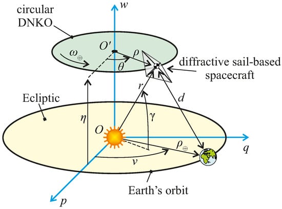
Figure 3.
Conceptual scheme of a circular heliocentric DNKO with a displacement equal to with respect to the Ecliptic. The green disk indicates the plane of the displaced orbit, which the spacecraft covers at a constant angular velocity at distance d from the Earth.
A circular DNKO is a circular orbit centered in , which belongs to the w-axis of constant radius . The plane of the displaced orbit (see the green disk in Figure 3) is parallel to the plane of the Ecliptic (i.e., the yellow disk in Figure 3) and the distance between the two planes is denoted by . Furthermore, the spacecraft travels along the circular DNKO at a constant angular velocity, which corresponds to the mean motion of the Earth around the Sun. For an assigned value of angular velocity, a circular DNKO may also be equivalently characterized by the angle of elevation , that is, the angle between the Sun–spacecraft line and the Ecliptic, and the Sun–spacecraft distance r, as sketched in Figure 3. Without loss of generality and consistently with a monitoring mission of the Earth’s high northern latitudes, in this paper, we assume that lies within the interval . Note that the pair can be written as a function of as
As will be better detailed in Section 3.1, the diffractive sail-based spacecraft is outside the Earth’s sphere of influence (SOI), and therefore, the perturbative effect of our planet can be neglected []. Paralleling the procedure proposed by McInnes [] for the reflecting solar sail and bearing in mind the scheme of Figure 4, the balance between propulsive, gravitational, and centrifugal accelerations acting on the spacecraft results in the following two scalar equations
which describe the spacecraft equilibrium in a rotating reference frame along and , respectively.
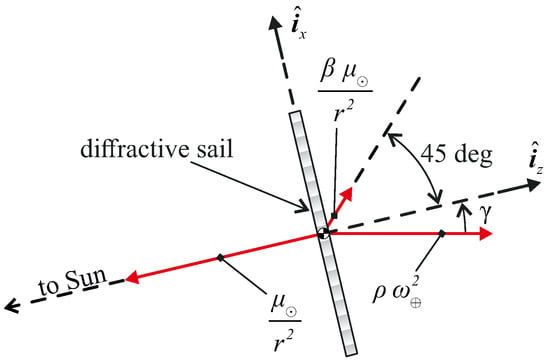
Figure 4.
Scheme of the gravitational, propulsive, and centrifugal forces per unit of mass acting on the diffractive sail-based spacecraft during the flight along the circular displaced orbit.
Now, by substituting Equation (7) into Equation (8) and using Equation (5), we obtain the following analytical result, which expresses the radius of the circular displaced orbit as a function of the angle of elevation and the reference distance , viz.
from which one obtains the values of as
while the required value of the lightness number is obtained by substituting Equations (5) and (9) into Equation (7). In that case, the result is
In this context, Figure 5 shows the variations of as a function of . Note that , , and when , while , , and when .
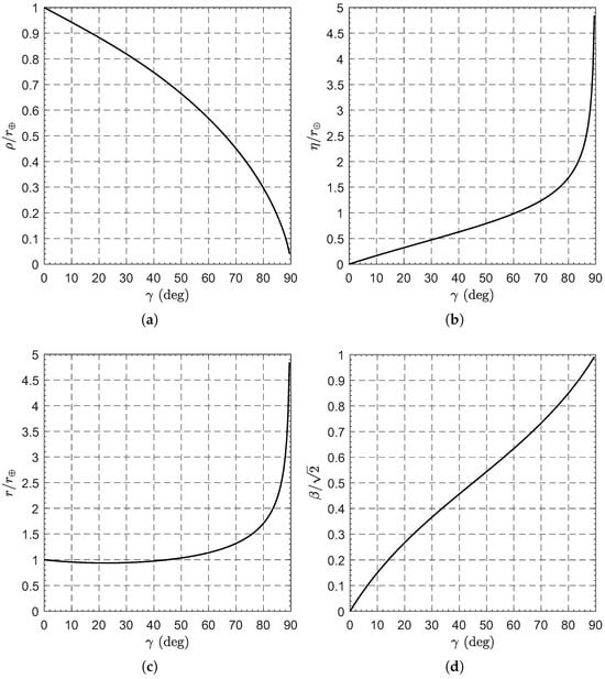
Figure 5.
Variations of with for a diffractive sail-based circular heliocentric DNKO. (a) Orbit radius. (b) Orbit displacement. (c) Sun–spacecraft distance. (d) Lightness number.
3.1. Earth–Spacecraft Distance
The effectiveness of a scientific mission to monitor the Earth’s high latitudes will be related to the distance of the spacecraft from the planet; see Figure 3. Therefore, in this subsection, we will quantify the Earth–spacecraft (instantaneous) distance, showing that it depends on three parameters, namely: the elevation angle, the Earth’s true anomaly, and the point in the Earth’s orbit at which the spacecraft and the Earth have the same angular position in the plane of the Ecliptic. For this purpose, consider the components of the Sun–spacecraft position vector in , that is
where is the angle between the projection of the vector on the Ecliptic and the p-axis, as sketched in Figure 3.
The components of the Sun–Earth position vector in , instead, are given by
where is the Sun–Earth distance, given by
in which is the eccentricity of the Earth’s heliocentric orbit and is the planet’s true anomaly. In particular, the value of is given by
where t is the time and is the angular offset between the diffractive sail-based spacecraft and the Earth at the reference time . The latter is here defined, without loss of generality, as the time instant at which the Earth passes perihelion, that is, . Therefore, the net of multiples of one year, and the time t can be written as a function of as
where is the eccentric anomaly of the Earth, given by
The value of may be determined backward from the value of (namely, ) where , which is the value of (assumed to exist) when the spacecraft and the Earth have the same angular position in the plane of the Ecliptic. Accordingly, the value of E when is given by
the corresponding time instant is
and
Bearing in mind that (see Equations (18) and (19)), then Equation (20) gives , which is plotted in Figure 6. Note that is maximum when and its value is about .
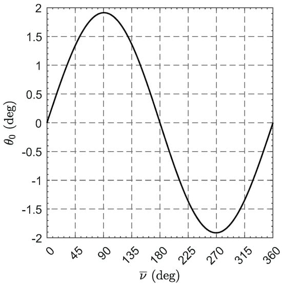
Figure 6.
Variation of with ; see also Equation (20).
In this context, the angular offset between the spacecraft and the Earth, defined as
is an explicit function of according to Equations (16)–(19), so it changes throughout the year. However, its mean integral value with respect to , that is, the function
turns out to coincide with the angular displacement between the diffractive sail-based spacecraft and the Earth when the latter passes to perihelion. In this sense, the distance d between the spacecraft and the Earth’s center of mass, given by
is an explicit function of and is represented in Figure 7 and Figure 8. Note that in the figures the values of d are reported in units of ; that is, in multiples of the Earth’s mean equatorial radius. In addition, Figure 8 also shows the radius of the Earth’s SOI, given by , which is a weak function of , the eccentricity of the Earth’s orbit being much smaller than 1.
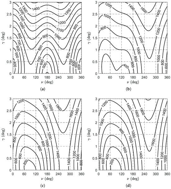
Figure 7.
Variation of the spacecraft–Earth distance d with . The contour lines indicate the values of d expressed in units of . (a) . (b) and . (c) and . (d) and .
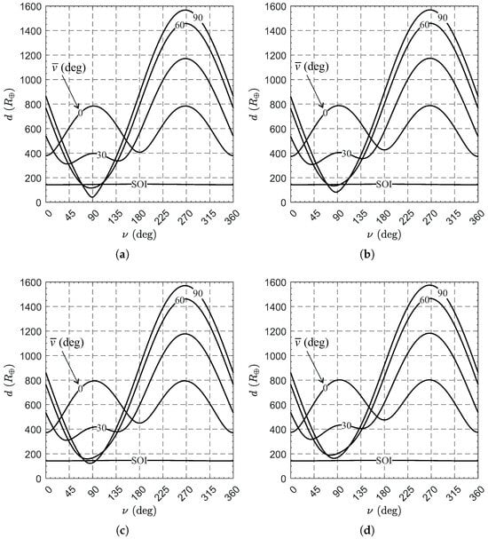
Figure 8.
Variation of the spacecraft–Earth distance d with . (a) , , and . (b) , , and . (c) , , and . (d) , , and .
An interesting result is that the condition , which describes the situation in which the angular offset between the spacecraft and the Earth has a zero mean value during the year, does not necessarily imply that the minimum value of d with respect to (i.e., the value of ) is as small as possible. In this regard, consider Figure 9, which shows the variation of with . Two important conclusions can be drawn from that figure.
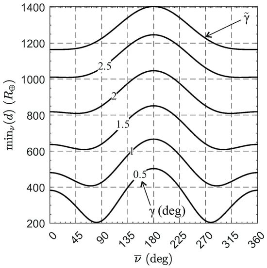
Figure 9.
Variation of the value of with for small values of .
The first is that, when due to , the value of is maximum for all values of . The second is that, when due to , the value of is minimum only over a specific value of , referred to as . Such a value of can be obtained by imposing that (see Equation (9)) is equal to the perihelion radius of the Earth’s orbit. This leads to the following equation
which is (numerically) solved for . For smaller values of (i.e., for ), the radius of the orbit is greater than the perihelion radius of the Earth’s orbit (i.e., ) and, therefore, the value of is minimum when the radius of the orbit is equal to Earth’s orbit, viz.
Figure 10 shows the variation of that minimizes as a function of . In particular, in the limiting case where , the value of is minimized when , that is, when .
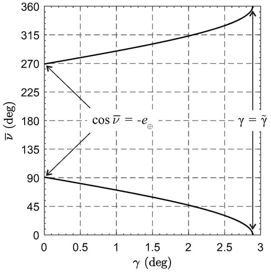
Figure 10.
Values of that minimize as a function of .
Finally, Figure 11 shows the variation of with for very small values of . From this figure it can be concluded that there is a value of (approximately equal to ) beyond which is greater than the Earth’s SOI for any value of .
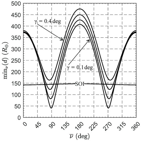
Figure 11.
Variation of the value of with for very small values of .
To summarize, the minimum Earth–spacecraft distance occurs when if and when
if .
3.2. Orbital Parameters of the Osculating Orbit
It is interesting to determine the orbital parameters of the spacecraft’s osculating orbit relative to the Sun. For example, these parameters are important in the study of transfer trajectories from Earth to the target (circular) DNKO. Therefore, consider Equation (10), which gives the Sun–spacecraft distance as a function of , and recall that the magnitude of the inertial velocity of the diffractive sail-based spacecraft is .
Accordingly, the specific mechanical energy () and angular momentum (h) of the spacecraft osculating orbit are given by
from which the semimajor axis (a) and the eccentricity (e) of the osculating orbit are
As far as the true anomaly (f) is concerned, from the orbit equation in polar form we have
or
where r, h, and e are given by Equations (10), (28), and (30), respectively. In particular, Equation (32) states that the spacecraft is at the aphelion or perihelion of its osculating orbit. This is a fairly obvious result since the spacecraft velocity is always perpendicular to its position vector with respect to the Sun.
Finally, the spatial orientation of the osculating orbit may be described with respect to a heliocentric-ecliptic reference frame with the aid of three independent parameters. Specifically, the inclination i describes the angle between the Ecliptic and the osculating orbit plane, the argument of perihelion describes the angle between the eccentricity vector of the osculating orbit and the position vector from the Sun to the ascending node, while the right ascension of the ascending node describes the angle between the p-axis and the position vector from the Sun to the ascending node. Observing that the plane of the osculating orbit is identified by the Sun–spacecraft position vector and the velocity vector of the spacecraft, and recalling Equation (32), it is immediate to conclude that
where is the value of at time . Therefore, five of the six orbital parameters of the spacecraft’s osculating orbit are constant during the monitoring mission, while varies linearly with time. This means that maintaining a circular DNKO is equivalent to achieving a linear precession of the line of nodes of the osculating orbit without changing the other orbital parameters (including the true anomaly).
In this context, Figure 12 shows the variations of of the osculating orbit as a function of ; that is, for values of that entail a closed osculating orbit.
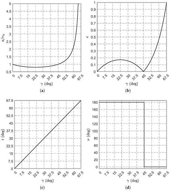
Figure 12.
Constant orbital parameters of the (closed) osculating orbit as a function of . (a) Semimajor axis. (b) Eccentricity. (c) Inclination. (d) True anomaly.
In particular, the spacecraft’s osculating orbit is an ellipse when , a parabola when , and a hyperbola when . Furthermore, the osculating orbit is circular when and, in such cases, . When the osculating orbit is an ellipse, the minimum of a is reached when and its value is , while the corresponding value of e (which is the maximum in the interval ) is . For example, if , then , , , , and .
3.3. Comparison with the Reflecting Solar Sail Case
The same family of circular DNKOs (that is, those maintained with a propulsive acceleration vector inclined by with respect to the Sun–spacecraft line) may also be maintained by means of a more common reflecting solar sail. In this case, assuming that the reflecting sail is ideal, Equations (7) and (8) become
where
is the lightness number of an ideal reflecting sail ( being the required surface area) and is the sail attitude necessary to maintain the desired family of circular DNKOs (subscript stands for “reflecting sail”). Note that the 2 coefficient in the numerator indicates that the sail reflects all incident light specularly. Substituting into Equations (34) and (35) and comparing the result with Equations (7) and (8) gives
For instance, the diffractive sail performs better than an ideal reflecting solar sail because, for the same value of m, an ideal reflecting sail needs an area exposed to the Sun greater by a factor of than that required by a diffractive solar sail.
4. Linear Stability Analysis
An important point to deal with is the stability analysis of the selected circular DNKO, which is addressed here by looking for the conditions that guarantee linearly stable motion. Paralleling the procedure described in Ref. [], consider the diffractive sail-based spacecraft equations of motion in the rotating cylindrical reference frame
where the dot symbol denotes a derivate taken with respect to time.
The perturbative dynamics is obtained by introducing an error in the initial position of the spacecraft, which models a possible error in orbital insertion. For this purpose, the radius and displacement of the initial orbit can be written as
where the subscript i denotes the reference (i.e., nominal) value ( being the start instant of the monitoring mission), while and (with and ) are the errors in orbital radius and displacement, respectively. It is also assumed that there is no error in the initial velocity (i.e., ). Note that, from Equation (39), it follows that is constant. In particular, we have
Using the latter transformation and recalling Equation (43), the linearized expressions of , , , and become
The perturbation equations are obtained from Equations (38) and (40) by subtracting the corresponding equilibrium equation written below
Accordingly, the perturbative equations become
where the prime symbol denotes a derivative taken with respect to the dimensionless time , while the coefficients are given by
Recalling that
The poles of the linearized system are the roots of the associated characteristic polynomial, that is
where
Since the characteristic Equation (61) is biquadratic, the marginal stability of the linearized system requires that its roots are purely imaginary. Therefore, the conditions to be met are and , which are both satisfied for any value of ; see Figure 13.
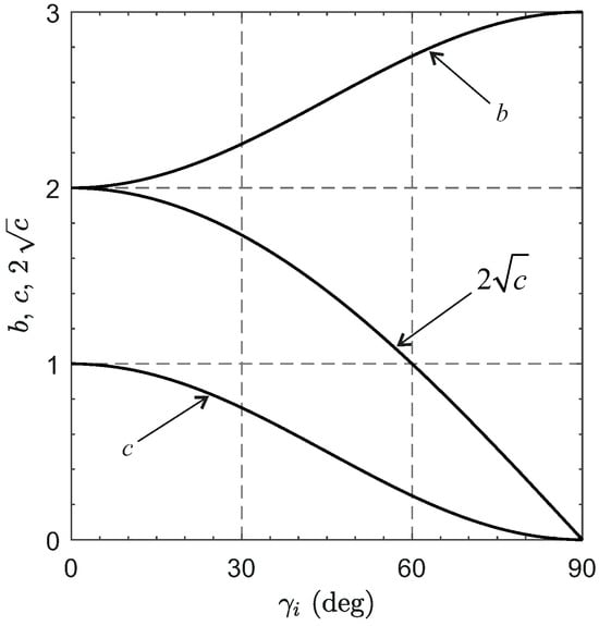
Figure 13.
Variations of with .
Note that the natural frequencies of the two pairs of purely imaginary poles are
According to the Lyapunov linearization method [], the marginal stability of the linearized dynamics is a necessary (but not sufficient) condition for the stability of the nonlinear system. Therefore, a numerical simulation was performed to verify the stability of the nonlinear dynamics, showing that the nonlinear system is indeed marginally stable, as discussed in the next subsection.
Potential Mission Application
Consider the problem of maintaining a diffractive sail-based spacecraft in a circular DNKO to continuously observe the Earth’s high-latitude regions. This case is similar to the pole-sitter mission concept described by Ceriotti et al. [], in which a solar electric thruster or a hybrid propulsion system (i.e., a combination of solar sail and solar electric thruster) is used to maintain an Earth–spacecraft distance of about to ensure proper spatial resolution for the scientific instruments. In this context, assuming , the stability of the complete dynamics is now checked by numerical simulation. In particular, Equations (38)–(40) are integrated in double precision using an Adams–Bashforth–Moulton solver scheme of variable order with absolute and relative errors of and , respectively, and a time interval of . The error in orbit insertion is modeled by assuming . Moreover, an error in the initial velocity is also considered for completeness. In particular, consider the radial (), azimuthal (), and normal () components of the spacecraft velocity, defined as
whose reference values are and , and assume that the errors in are . The simulation results involving normalized distance () and elevation angle () are shown in Figure 14a, while the time-variations of the velocity components are illustrated in Figure 14b. From the results it can be concluded that the system is marginally stable (in fact, no damping source is included in the model), even when errors in spacecraft velocity components are considered.
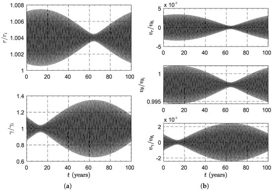
Figure 14.
Simulation results for the case study. (a) Time variations of . (b) Time variations of .
5. Conclusions
In this paper, we have investigated the possibility of maintaining circular displaced non-Keplerian orbits with a Sun-facing diffractive sail. An analytical solution has been proposed that analytically relates the radius of the spacecraft orbit and the required lightness number to the elevation angle. In particular, we have shown that there is a value (approximately equal to ) beyond which the Earth–spacecraft distance is greater than the radius of the Earth’s SOI regardless of the angular offset between the spacecraft and the Earth at the instant our planet passes to perihelion.
For the purpose of generating the same family of displaced non-Keplerian orbits (i.e., those requiring the same radial and transverse thrust components), it has been shown that a diffractive sail performs better than an ideal reflecting sail because, for the same total spacecraft mass, it requires a surface area exposed to the Sun that is smaller by a factor of . Finally, numerical simulations have shown that these orbits are marginally stable. A possible extension of this work is to consider a change in attitude of the diffractive sail during flight in order to generate a displaced elliptical orbit of given characteristics.
Author Contributions
Conceptualization, A.A.Q.; methodology, M.B.; software, M.B.; writing—original draft preparation, M.B. and G.M.; writing—review and editing, all authors. All authors have read and agreed to the published version of the manuscript.
Funding
This research received no external funding.
Institutional Review Board Statement
Not applicable.
Informed Consent Statement
Not applicable.
Data Availability Statement
Data are contained within the article.
Conflicts of Interest
The authors declare no conflict of interest.
References
- Zhao, P.; Wu, C.; Li, Y. Design and application of solar sailing: A review on key technologies. Chin. J. Aeronaut. 2023, 36, 125–144. [Google Scholar] [CrossRef]
- Fu, B.; Sperber, E.; Eke, F. Solar sail technology—A state of the art review. Prog. Aerosp. Sci. 2016, 86, 1–19. [Google Scholar] [CrossRef]
- Gong, S.; Macdonald, M. Review on solar sail technology. Astrodynamics 2019, 3, 93–125. [Google Scholar] [CrossRef]
- Vulpetti, G.; Scaglione, S. The Aurora project: Estimation of the optical sail parameters. Acta Astronaut. 1999, 44, 123–132. [Google Scholar] [CrossRef]
- Rozhkov, M.A.; Starinova, O.L.; Chernyakina, I.V. Influence of optical parameters on a solar sail motion. Adv. Space Res. 2021, 67, 2757–2766. [Google Scholar] [CrossRef]
- Davoyan, A.R.; Munday, J.N.; Tabiryan, N.; Swartzlander, G.A.; Johnson, L. Photonic materials for interstellar solar sailing. Optica 2021, 8, 722–734. [Google Scholar] [CrossRef]
- Firuzi, S.; Gong, S. Refractive sail and its applications in solar sailing. Aerosp. Sci. Technol. 2018, 77, 362–372. [Google Scholar] [CrossRef]
- Firuzi, S.; Song, Y.; Gong, S. Gradient-index solar sail and its optimal orbital control. Aerosp. Sci. Technol. 2021, 119, 107103. [Google Scholar] [CrossRef]
- Bassetto, M.; Quarta, A.A.; Mengali, G. Generalized sail trajectory approximation with applications to MagSails. Aerosp. Sci. Technol. 2021, 118, 106991. [Google Scholar] [CrossRef]
- Swartzlander, G.A., Jr. Radiation pressure on a diffractive sailcraft. J. Opt. Soc. Am. B Opt. Phys. 2017, 34, C25–C30. [Google Scholar] [CrossRef]
- Swartzlander, G.A., Jr. Flying on a rainbow: A solar-driven diffractive sailcraft. JBIS-J. Br. Interplanet. Soc. 2018, 71, 130–132. [Google Scholar]
- Dubill, A.L.; Swartzlander, G.A., Jr. Circumnavigating the Sun with diffractive solar sails. Acta Astronaut. 2021, 187, 190–195. [Google Scholar] [CrossRef]
- Quarta, A.A.; Mengali, G.; Bassetto, M.; Niccolai, L. Optimal interplanetary trajectories for Sun-facing ideal diffractive sails. Astrodynamics 2023, 7, 285–299. [Google Scholar] [CrossRef]
- Quarta, A.A.; Mengali, G. Solar sail orbit raising with electro-optically controlled diffractive film. Appl. Sci. 2023, 13, 7078. [Google Scholar] [CrossRef]
- Svetlana, V.S.; Roberts, D.E.; Hwang, J.Y.; Nersisyan, S.R.; Tabiryan, N.V.; Bunning, T.J.; Steeves, D.M.; Kimball, B.R. Diffractive waveplate arrays. J. Opt. Soc. Am. B Opt. Phys. 2017, 34, 56–63. [Google Scholar] [CrossRef]
- Srivastava, P.R.; Lucy Chu, Y.J.; Swartzlander, G.A., Jr. Stable diffractive beam rider. Opt. Lett. 2019, 44, 3082–3085. [Google Scholar] [CrossRef] [PubMed]
- Srivastava, P.R.; Swartzlander, G.A., Jr. Optomechanics of a stable diffractive axicon light sail. Eur. Phys. J. Plus 2020, 135, 570. [Google Scholar] [CrossRef] [PubMed]
- Chu, Y.; Firuzi, S.; Gong, S. Controllable liquid crystal diffractive sail and its potential applications. Acta Astronaut. 2021, 182, 37–45. [Google Scholar] [CrossRef]
- Lucy Chu, Y.L.; Meem, M.; Srivastava, P.R.; Menon, R.; Swartzlander, G.A., Jr. Parametric control of a diffractive axicon beam rider. Opt. Lett. 2021, 46, 5141–5144. [Google Scholar] [CrossRef]
- McInnes, C.R. Dynamics, stability, and control of displaced non-Keplerian orbits. J. Guid. Control Dyn. 1998, 21, 799–805. [Google Scholar] [CrossRef]
- McInnes, C.R. Displaced non-Keplerian orbits using impulsive thrust. Celest. Mech. Dyn. Astron. 2011, 110, 199–215. [Google Scholar] [CrossRef][Green Version]
- Caruso, A.; Quarta, A.A.; Mengali, G. Elliptic displaced orbit approximation with equally spaced impulses. J. Guid. Control Dyn. 2019, 42, 411–415. [Google Scholar] [CrossRef]
- Pan, X.; Xu, M. Overview of non-Keplerian displaced orbits by low-thrust propulsion. Chin. Space Sci. Technol. 2021, 41, 1–15. [Google Scholar] [CrossRef]
- Pan, X.; Xu, M.; Huang, H.; Pei, X.; Dong, Y. Nonlinear dynamics of displaced non-Keplerian orbits with low-thrust propulsion. Commun. Nonlinear Sci. Numer. Simul. 2019, 66, 61–83. [Google Scholar] [CrossRef]
- McKay, R.J.; MacDonald, M.; Biggs, J.; McInnes, C. Survey of highly-non-Keplerian orbits with low-thrust propulsion. J. Guid. Control Dyn. 2011, 34, 645–666. [Google Scholar] [CrossRef]
- Bookless, J.; McInnes, C.R. Dynamics and control of displaced periodic orbits using solar-sail propulsion. J. Guid. Control Dyn. 2006, 29, 527–537. [Google Scholar] [CrossRef]
- Gong, S.; Baoyin, H.; Li, J. Relative orbit design and control of formation around displaced solar orbits. Aerosp. Sci. Technol. 2008, 12, 195–201. [Google Scholar] [CrossRef]
- Gong, S.; Li, J. Spin-stabilized solar sail for displaced solar orbits. Aerosp. Sci. Technol. 2014, 32, 188–199. [Google Scholar] [CrossRef]
- Song, M.; He, X.; He, D. Displaced orbits for solar sail equipped with reflectance control devices in Hill’s restricted three-body problem with oblateness. Astrophys. Space Sci. 2016, 361, 327. [Google Scholar] [CrossRef]
- Bassetto, M.; Quarta, A.A.; Mengali, G. Magnetic sail-based displaced non-Keplerian orbits. Aerosp. Sci. Technol. 2019, 92, 363–372. [Google Scholar] [CrossRef]
- Zubrin, R.M.; Andrews, D.G. Magnetic sails and interplanetary travel. J. Spacecr. Rocket. 1991, 28, 197–203. [Google Scholar] [CrossRef]
- Andrews, D.G.; Zubrin, R.M. Magnetic sails and interstellar travel. J. Br. Interplanet. Soc. 1990, 43, 265–272. [Google Scholar]
- Zubrin, R.M. The use of magnetic sails to escape from low Earth orbit. J. Br. Interplanet. Soc. 1992, 46, 3–10. [Google Scholar] [CrossRef]
- McInnes, C.R. Solar Sailing: Technology, Dynamics and Mission Applications; Springer-Praxis Series in Space Science and Technology; Springer: Berlin, Germany, 1999; Chapter 2; pp. 46–54. [Google Scholar] [CrossRef]
- Wright, J.L. Space Sailing; Gordon and Breach Science Publishers: Amsterdam, The Netherlands, 1992; pp. 223–233. ISBN 978-2881248429. [Google Scholar]
- Pathak, S. Nanoelectronics: Devices, Circuits and Systems. In Nanoelectronics; Kaushik, B.K., Ed.; Advanced Nanomaterials; Elsevier: Amsterdam, The Netherlands, 2019; Chapter 7; pp. 219–270. [Google Scholar] [CrossRef]
- Mengali, G.; Quarta, A.A. Non-Keplerian orbits for electric sails. Celest. Mech. Dyn. Astron. 2009, 105, 179–195. [Google Scholar] [CrossRef]
- Bate, R.R.; Mueller, D.D.; White, J.E. Fundamentals of Astrodynamics; Dover Publications: New York, NY, USA, 1971; Chapter 1; p. 40. [Google Scholar]
- Slotine, J.E.; Li, W. Applied Nonlinear Control; Prentice-Hall: Englewood Cliffs, NJ, USA, 1991; Chapter 3; pp. 53–57. [Google Scholar]
- Ceriotti, M.; Heiligers, J.; McInnes, C.R. Trajectory and spacecraft design for a pole-sitter mission. J. Spacecr. Rocket. 2014, 51, 311–326. [Google Scholar] [CrossRef]
Disclaimer/Publisher’s Note: The statements, opinions and data contained in all publications are solely those of the individual author(s) and contributor(s) and not of MDPI and/or the editor(s). MDPI and/or the editor(s) disclaim responsibility for any injury to people or property resulting from any ideas, methods, instructions or products referred to in the content. |
© 2023 by the authors. Licensee MDPI, Basel, Switzerland. This article is an open access article distributed under the terms and conditions of the Creative Commons Attribution (CC BY) license (https://creativecommons.org/licenses/by/4.0/).