Article

Optimizing Image Compression Ratio for Generating Highly Accurate Local Digital Terrain Models: Experimental Study for Martian Moons eXploration Mission

1
Department of Systems Innovation, The University of Tokyo, Tokyo 1138656, Japan
2
Department of Physics, Rikkyo University, Tokyo 1718501, Japan
*
Author to whom correspondence should be addressed.
Remote Sens. 2023, 15(23), 5500; https://doi.org/10.3390/rs15235500
Submission received: 14 October 2023 / Revised: 17 November 2023 / Accepted: 23 November 2023 / Published: 25 November 2023
(This article belongs to the Special Issue Planetary Geodesy and Geophysics of Asteroid: Data and Modeling)

Abstract

:
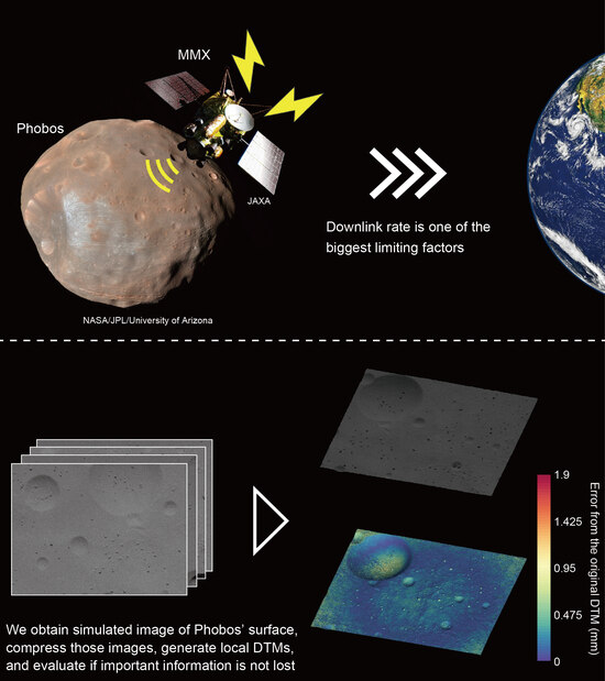
Recent technological advances have significantly increased the data volume obtained from deep space exploration missions, making the downlink rate a primary limiting factor. Particularly, JAXA’s Martian Moons eXploration (MMX) mission encounters this problem when identifying safe and scientifically valuable landing sites on Phobos using high-resolution images. A strategic approach in which we effectively reduce image data volumes without compromising essential scientific information is thus required. In this work, we investigate the influence of image data compression, especially as it concerns the accuracy of generating the local Digital Terrain Models (DTMs) that will be used to determine MMX’s landing sites. We obtain simulated images of Phobos that are compressed using the algorithm with integer/float-point discrete wavelet transform (DWT) defined by the Consultative Committee for Space Data Systems (CCSDS), which are candidate algorithms for the MMX mission. Accordingly, we show that, if the compression ratio is 70% or lower, the effect of image compression remains constrained, and local DTMs can be generated within altitude errors of 40 cm on the surface of Phobos, which is ideal for selecting safe landing spots. We conclude that the compression ratio can be increased as high as 70%, and such compression enables us to facilitate critical phases in the MMX mission even with the limited downlink rate.

Graphical Abstract

1. Introduction

In situ observations from robotic explorations, such as the Hayabusa [1], Hayabusa2 [2], Rosetta [3], and OSIRIS-REx (Origins, Spectral Interpretation, Resource Identification, Security, Regolith Explorer) [4] missions, have significantly contributed to expanding our understanding of the solar system. Subsequently, more deep space exploration missions are planned to be launched [5,6,7,8]. In these exploration missions, we can expect to obtain a large amount of scientific data relatively easily due to recent technological advances. However, the longer distances between spacecraft and the ground, coupled with limited transmission power constrained by several factors such as antenna size and power consumption, often result in significantly low downlink rates. Smart data handling strategies must, in this regard, be considered within the constraints of limited downlink rates to maximize scientific returns from future deep space exploration missions.
The limited downlink speed can be one of the biggest issues for the Japan Aerospace Exploration Agency (JAXA)’s Martian Moons eXploration (MMX) mission, which is scheduled to be launched in 2024 [9]. Specifically, this mission will explore the moons of Mars, Phobos, and Deimos to determine their origins and evolutions. There are several theories on the formation mechanisms of the two moons. The basic parameters, such as their small sizes, low bulk densities, irregular shapes, and low albedos, and the visible to near-infrared reflectance spectra lead to the captured asteroid origin theory, where primitive carbonaceous chondrites originating at the outside of Mars’s system could be captured by Mars’s gravity [10,11,12]. On the other hand, their orbital parameters, including the low orbital inclinations and eccentricities, and some numerical studies support the giant impact origin theory, where ejecta materials could accrete and form the moons after a giant impact on Mars [13,14,15,16,17,18,19].
To conclude this discussion about the origins, the MMX mission is planned to perform landings on Phobos (ideally two times on different sites) and collect surface materials ( 10   g ), which will be returned to Earth in 2029 and analyzed in laboratories [9]. Although previous missions such as the Hayabusa [1], Hayabusa2 [2], and OSIRIS-REx [4] missions performed touchdowns (instant contacts on the surfaces within a second) and collected samples from the surfaces of asteroids, the landing and sampling in MMX missions have become more challenging in that the spacecraft will have to safely land and stay for approximately 2.5 h on Phobos [20], where knowledge of the surface is limited. Nevertheless, Phobos is expected to contain plenty of topographic irregularities including slopes [21], craters [22,23,24,25,26,27], rock particles (i.e., boulders, cobbles, and pebbles) [28], and grooves [23,24,28,29,30,31]. The gravity of Phobos (~1/2000 G [32]) is also relatively higher than on any other small asteroids on which touchdowns were previously performed ( ~ 1 / 10 5 1 / 10 4 G [33,34,35,36,37]), so the landing site selection could be one of the most crucial phases for this mission.
Based on the current specifications of MMX spacecraft, we need to find flat regions with altitude differences smaller than 40 cm [38]. Although previous missions, such as the Mariner-9 [39], Viking-Orbiter [40], Mars Global Surveyor [28], Mars Express [41], Mars Reconnaissance Orbiter [42], and Emirates Mars [43] missions have observed Phobos or Deimos thus far, the resolutions of obtained optical images and three-dimensional shape models are insufficient considering this severe requirement for the landing sites. While some numerical studies have indicated the capability of finding smooth enough regions for the landing on Phobos [38], if we establish the safety of the spacecraft during landing as the ultimate priority, then the most practical strategy is performing in situ observations after the arrival and finding safe regions for the landings.
The MMX spacecraft is thus equipped with two optical cameras: the Telescopic Nadir Imager for GeOmOrphology (TENGOO) and the Optical RadiOmeter Composed of CHromatic Imagers (OROCHI) [44]. The high-resolution image capabilities of these cameras are critical for landing site selection. To map Phobos’s surface with a resolution of ~12 cm/pix from a quasi-satellite orbit (QSO) around the moon, the cameras have been designed to exhibit superior performance in comparison to optical cameras on previous sample return missions, such as AMICA of Hayabusa [45], ONC-T of Hayabusa2 [46], and OCAMS of OSIRIS-REx [47] missions. With a 3296 × 2472 pixel image size and a 16-bit depth, these specifications are significantly advantageous for minutely observing Phobos’s surface. However, this increased resolution results in a substantial image file size growth, with raw images potentially reaching 16.3 MB. Transmitting such large images to the ground could require over 1.1 h when utilizing the MMX’s typical telecommunication system with a speed of ~32 Kbps. This downlink duration is not practical given the limited observational period of the landing site selection, which is scheduled to be performed within approximately half a year and is severely constrained by illumination conditions determined by the relative positions of the spacecraft, Phobos, Mars, and the sun [20]. Additionally, the precise sample collection locations must be determined within the brief 2.5 h landing window, allowing under 1 h for downlinks.
One reasonable operation for transmitting such image data is to utilize data compression techniques, with numerous lossy compression algorithms that have been developed to reduce image file sizes significantly. Nonetheless, highly compressed images can become distorted and scientifically unusable. Optimizing image data handling, which will ensure data volume reduction without compromising scientific value, is, therefore, significant for future deep space exploration missions, including the MMX mission. While previous studies have analyzed the influence of data compression on images of exploration missions [48,49], to fulfill the requirements of the landing operations of the MMX mission, we mainly focus on the effect of image compression on the accuracy of local DTM generation to show whether such compressions lose any critical information necessary for selecting safe landing sites on Phobos (i.e., ~40 cm altitude differences).

2. Materials and Methods

2.1. Experimental Setup

Although previous studies showed the existence of various geological characteristics on Phobos, including craters, grooves, and boulders [23,24,28], the spatial resolutions of the images obtained by previous exploration missions are limited (lower than several meters per pixel), and the detail of the roughness is still unknown [38]. This knowledge gap will remain until the MMX spacecraft arrives at Phobos and reveals detailed surface structures through high-resolution images. Accordingly, we prepared simulated images of Phobos with both rough and smooth surfaces to accurately evaluate the influence of image compression on the selection of landing sites under various surface conditions of Phobos.
For the simulated images of a rough surface, we used the simulator for the OROCHI, an optical chromatic imager onboard the MMX spacecraft [44]. This OROCHI simulator has seven wide-angle bandpass imagers, with a pixel pitch of 5.86 μ m and a focal length of 12.5 mm, achieving an iFoV of 0.469 mrad/pix, which is similar to the iFoV of the OROCHI (0.44–0.46 mrad/pix [44]). The seven band-pass filters have wavelengths of 390 nm, 480 nm, 550 nm, 650 nm, 700 nm, 800 nm, and 950 nm, respectively (Figure 1a). Furthermore, these imagers are mounted on an aluminum frame and can operate simultaneously, allowing the camera to capture the same region on the Phobos surface in seven different colors, which is useful for determining suitable landing sites and identifying the uniformity or nonuniformity of the distribution of surface materials. In this study, we mainly focus on images obtained by the imager with the band-pass filter having the wavelength of 550 nm, a wavelength commonly used in previous exploration missions, including the Hayabusa and Hayabusa2 missions [45,46]. For the surface material, we used the University of Tokyo Phobos Simulant, Tagish Lake Based (UTPS-TB) [50]. This simulated Phobos regolith material is developed and processed using terrestrial soils and materials, exhibiting a reflectance spectrum similar to that of Phobos surface materials, which allows for the acquisition of images that closely resemble those anticipated from the MMX mission.
The images were obtained with the following experimental setup (Figure 1b). UTPS-TB was spread over a foundation with a size of approximately 60 × 120 cm. The OROCHI simulator was fixed to a frame to prevent image blurring due to camera shake. This frame can be moved to capture images from different regions using the same imager. Images were taken from a height of approximately 70 cm directly above the foundation. A halogen lamp, whose wavelength domain was not covered by the seven band-pass filters, served as the light source, with an incidence angle (phase angle) of 30 ° , an optimal angle for observing surface rocks. Each image had a size of 1920 × 1200 pixels. Note that TENGOO and OROCHI use a 14-bit A/D converter, while the data are stored with a bit depth of 16 bits. To simulate this data structure, we converted 8-bit color images from the OROCHI simulator to 16-bit grayscale images, ensuring that each pixel value fell within the 14-bit depth range. Also, the OROCHI simulator images contained a dark surrounding frame due to the band-pass filters, which we excluded in the post-processing, as explained in Section 2.3.
With a similar procedure, we obtained simulated images of Phobos with a smooth surface (Figure 1c). In this experiment, we used a digital camera commercially available to simulate the same image size as OROCHI and TENGOO ( 3296 × 2472 pixels). We used a foundation with a size of 75 × 150 cm having circular depressions, which simulated craters on Phobos. Also, we spread UTPS-TB over the foundation as a surface material. Images were obtained from a height of approximately 188 cm above the foundation. As for the procedure of the simulated images for the smooth surface, we converted 16-bit color images to 16-bit grayscale images to simulate the conditions of TENGOO and OROCHI.

2.2. Image Compression

The compression algorithm used in the MMX mission was specially developed by the manufacturer of the TENGOO and OROCHI. Although this algorithm is proprietary and not publicly available, we have verified that images compressed using this algorithm perfectly match with images compressed by the algorithm defined in the CCSDS 122.0-B-1. CCSDS 122.0-B-1 is a document, generally referred to as Blue Book, showing a recommended standard of image data compression specialized for use in spacecraft. Because the complexity of the algorithm defined in this book is sufficiently low, images can be compressed rapidly even with hardware onboard spacecraft, including the MMX. Thus, we used this algorithm to compress images in this study.
Note that the CCSDS 122.0-B-1 was recently updated to the CCSDS 122.0-B-2. Also, there is another algorithm defined in the CCSDS 123.0-B-2, along with other common algorithms such as JPEG, JPEG2000, JPEG-LS, which may offer better performance compared to the algorithm defined in the CCSDS 122.0-B-1. However, robustness and a significantly low probability of program errors or malfunction during image compression are essential requirements for the MMX mission. The algorithm adopted in the MMX mission, which has consistent outputs with the CCSDS 122.0-B-1, has passed countless severe tests performed by the manufacturer of the MMX spacecraft to show whether the algorithm fulfills these requirements. Therefore, we mainly focused on the algorithm defined in the CCSDS 122.0-B-1 in this work and performance comparisons with other compression algorithms could be a topic for further studies.
Image compression algorithms commonly perform two compression schemes: lossless and lossy compressions. In lossless compression, the original image data can be fully reproduced, while the compression ratio is substantially low (i.e., high data volume of a resulting product). Conversely, in lossy compression, the original image data cannot be fully recovered, but the compression ratio can be significantly high (i.e., low data volume of a resulting product). Considering the limited downlink rate of deep space exploration missions, including the MMX mission, low data volume of a resulting product is important, and thus, we mainly focused on the image-handling strategies using lossy compression. Note that some algorithms, including the one defined in the CCSDS 123.0-B-2, offer near-lossless compression, where the maximum error in the reconstructed image can be limited, while the data volume can be significantly compressed. However, the algorithm adopted in the MMX mission, as well as the one defined in CCSDS 122.0-B-1, does not support near-lossless compression. Therefore, in this study, we did not consider near-lossless compression.
The image compression algorithm defined in the CCSDS 122.0-B-1 (hereafter simply referred to as CCSDS) consists of two functional parts: a Discrete Wavelet Transform (DWT) module that performs decorrelation, and a Bit-Plane Encoder (BPE) which encodes the decorrelated data. The CCSDS supports two different types of DWT: integer-point DWT and float-point DWT, and a choice of DWT leads to slightly different procedures during image compression. The integer-point DWT requires integer arithmetic, and offers lossless compression, but it can also be used in lossy compression. Following the DWT, the wavelet coefficients are scaled using the weight factors before the encoding performed in the BPE. On the other hand, the float-point DWT requires floating-point calculations, and it can be used only for lossy compression. Following the DWT, the wavelet coefficients are rounded to the nearest integer before encoding in the BPE. Importantly, whether these two algorithms have consistent compression performances for images from extraterrestrial bodies, especially Phobos, has yet to be revealed. Therefore, this study examined both algorithms using integer and float points to determine the best compression scheme.
In practice, we used a public script published by the University of Nebraska (http://hyperspectral.unl.edu/download.htm) (accessed on 18 November 2023) for image compression using CCSDS. In this study, the compression ratio p is defined as follows:
p = 1 S c o m p . S o r g . × 100   % ,
where S c o m p . and S o r g . are the file sizes of compressed and original images, respectively. Note that during the CCSDS encoding process, only the number of bits per pixel specified by the user is utilized, leading to a partial reconstruction of the input image, which is essentially the compression process. Therefore, we controlled the compression ratio by adjusting the value that indicates the number of bits per pixel to be used during encoding.

2.3. Image Quality Assessment

We used several evaluation metrics to assess the influence of image compression on image quality, which included Peak Signal-to-Noise Ratio (PSNR), Signal-to-Noise Ratio (SNR), and Strucural SIMilarity (SSIM). PSNR is one of the most widely used image quality indices, representing the ratio between the maximum possible power of the image and the power of distorting noise that affect the quality of the image. PSNR is defined as
P S N R = log 10 2 B 1 M S E   d B ,
where B represents the dynamic range of an image (in bits). Also, M S E is Mean Squared Error, which is expressed as
M S E = 1 w · h i j x i ,   j x ^ i ,   j 2 ,
where w and h denote the image width and height, respectively. x i ,   j and x ^ i ,   j represent the original and reconstructed pixel value in the i th row and j th column of the original and compressed images, respectively. The higher PSNR shows the higher quality of a reconstructed image.
SNR is also a common metric used not only for image quality analysis but for performance analysis of scientific instruments onboard spacecraft. Especially, we introduced SNR to evaluate the influence of image compression with the performance requirements of the camera onboard MMX [44]. In this study, SNR is defined as
S N R = P s i g n a l P n o i s e = 1 w · h i j x i ,   j 2 M S E
where P s i g n a l and P n o i s e show the powers of the original image and the difference between the original and compressed images. The higher SNR also shows the higher quality of a reconstructed image.
Additionally, we analyzed the influence of image compression by using SSIM, which is also one of the most widely used image quality indices [51]. Essentially, the SSIM evaluates image quality based on three comparisons: luminance, contrast, and structure comparisons. SSIM values range from 0.0 to 1.0, where a higher value indicates better image quality. A value of 1.0 shows that a given image is identical to the original image. Importantly, compared to PSNR and SNR, SSIM is more specialized to evaluate image quality in terms of visual perceptions of objects in images [51], which is fundamentally important to recognize hazardous objects on Phobos and to identify the same objects or textures existing in multiple images in order to accurately generate local DTMs (i.e., key point matching, described in Section 2.4).

2.4. Generation of Local DTMs

Structure from Motion (SfM) is one of the most famous and widely used algorithms to generate three-dimensional shape models from images obtained by satellites, drones, and spacecraft, for instance. The planetary science domain has utilized SfM in addition to several other conventional techniques, such as aerial photogrammetric approaches based on stereo pairs [52], and small digital topography/albedo maps (L-map) determined from multiple images with stereophotoclinometry (SPC) [53]. A recent study revealed that the SfM’s accuracy is compatible with SPC [54]. In the MMX mission, SfM is considered a reasonable algorithm for generating local Digital Terrain Models (DTMs). Thus, we used SfM to generate local DTMs.
In practice, we utilized Metashape Pro (ver. 1.6.4), a commercial software program for generating three-dimensional shape models. We utilized parameters that are recommended for generating local DTMs with the highest possible accuracy as shown in Table 1, although they significantly demand computational resources. To address this, we utilized high-end CPUs and GPUs (CPU of Core-i9 12900K and dual GPUs of GeForce RTX 3090) and reduced calculation times. Note that in the MMX mission, once we obtain images from the spacecraft, we need to generate countless local DTMs at the ground stations. This aims to quickly understand the detailed topographies of Phobos’s surface and select the best landing spots using these DTMs. Furthermore, such generation of the models should be performed repeatedly over ~6 months during the landing selection phase [20], as we need to update local DTMs when we obtain images with higher spatial resolutions or better observational conditions. Therefore, the process of generating multiple local DTMs with the highest possible accuracy, combined with the acceleration of processing time, as performed in this study, will be a crucial part of the preparation for the upcoming landing site selection phase in the MMX mission.
Local DTMs were created with Metashape through the following processes:
  • Import images and image masks (i.e., binary images determining the processing areas) and set camera parameters (e.g., focal length and sensor pixel sizes).
  • Georeference cameras by importing camera coordinate files, which define positions (coordinates) and orientations (directions) for each camera.
  • Perform key point matching by identifying distinctive features in images that can be recognized in other images and matching the most prominent features across the image dataset.
  • Perform bundle adjustment for three-dimensional geometry reconstruction using the network of matched features, incrementally adding images to update camera model parameters (e.g., focal length, radial distortion parameters) and camera orientations (i.e., positions, directions), and calculating three-dimensional coordinates for key points.
  • Generate a sparse point cloud representing the three-dimensional coordinates of the most prominent features in the image dataset, realign images with large coordinate errors, and remove outliers by observing the point cloud from various directions.
  • Build a dense point cloud by calculating depth and color information for each camera.
  • Generate polygon meshes from the dense point cloud that express a detailed topography of the target shape.
  • Generate image masks by selecting areas on the mesh with high confidence, created from many points in the dense point cloud. Using those image masks, regenerate the model.
  • Generate the model’s texture by combining the original images seamlessly with the reconstructed polygon meshes.
Note that, to generate local DTMs with high quality, the amount of overlapping area in each image with other images is important. This scenario occurs because the large overlapping area leads to many reconstructed point clouds, resulting in a better quality of local DTMs. Thus, we first created models without any image masks (by Step 7). Then, we selected an area on each model where a large number of point clouds are reconstructed and generated image masks. Using these masks, we processed only portions in each image with large overlaps with others and improved the quality of local DTMs (Step 8).

3. Results

3.1. Phobos Simulated Images and Local DTMs

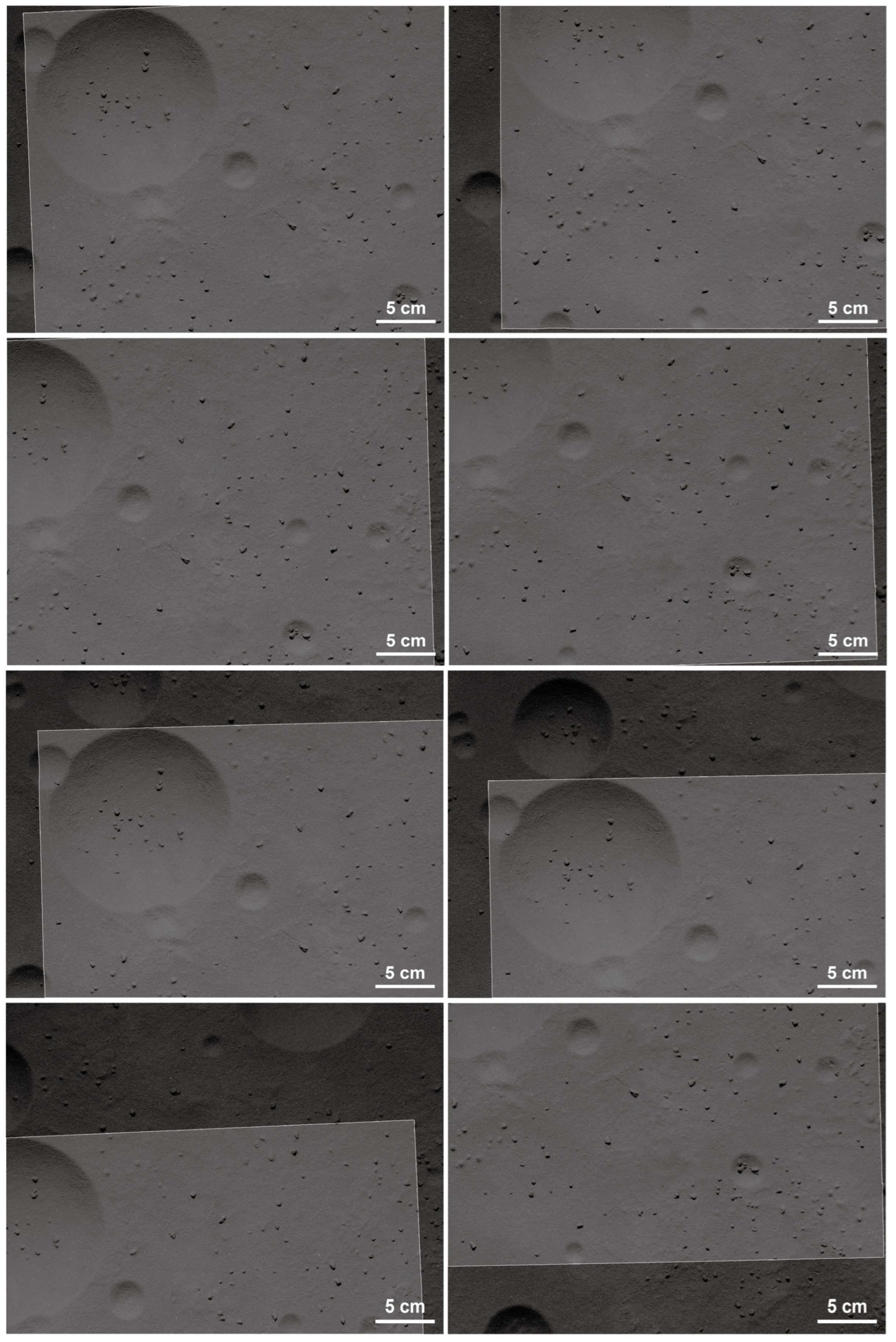
Figure 2 and Figure 3 show examples of the simulated images of Phobos with rough and smooth surfaces, respectively. Using the experimental setup with the rough surface, we obtained 10 images. The spatial resolution of these images is 0.379 mm/pix. On the other hand, by utilizing the experimental setup with the smooth surface, we acquired 44 images at a spatial resolution of 0.112 mm/pix.
Using these simulated images, we generated local DTMs for both rough and smooth surfaces (Figure 4a). For the rough surface model, we created a dense point cloud composed of 3,826,280 points, resulting in a mesh with 2,309,668 facets. The standard deviation of the elevation is 19.2 mm (Figure 5a). On the other hand, for the smooth surface model, we generated a dense point cloud containing 13,265,901 points, resulting in a mesh with 10,012,252 facets (Figure 4b). The standard deviation of the elevation is 8.99 mm, which is smaller than that of the rough surface model and indicates this model’s smoothness (Figure 5b). In this manner, we generated local DTMs having a substantially large number of facets, which are compatible with models that will be generated in the MMX mission. Note that generating local DTMs demanded ~3 min for the rough surface, compared to ~10 min for the smooth surface. They needed approximately 60% longer processing time if they were processed with a single GPU.

3.2. Influence of Image Compressions

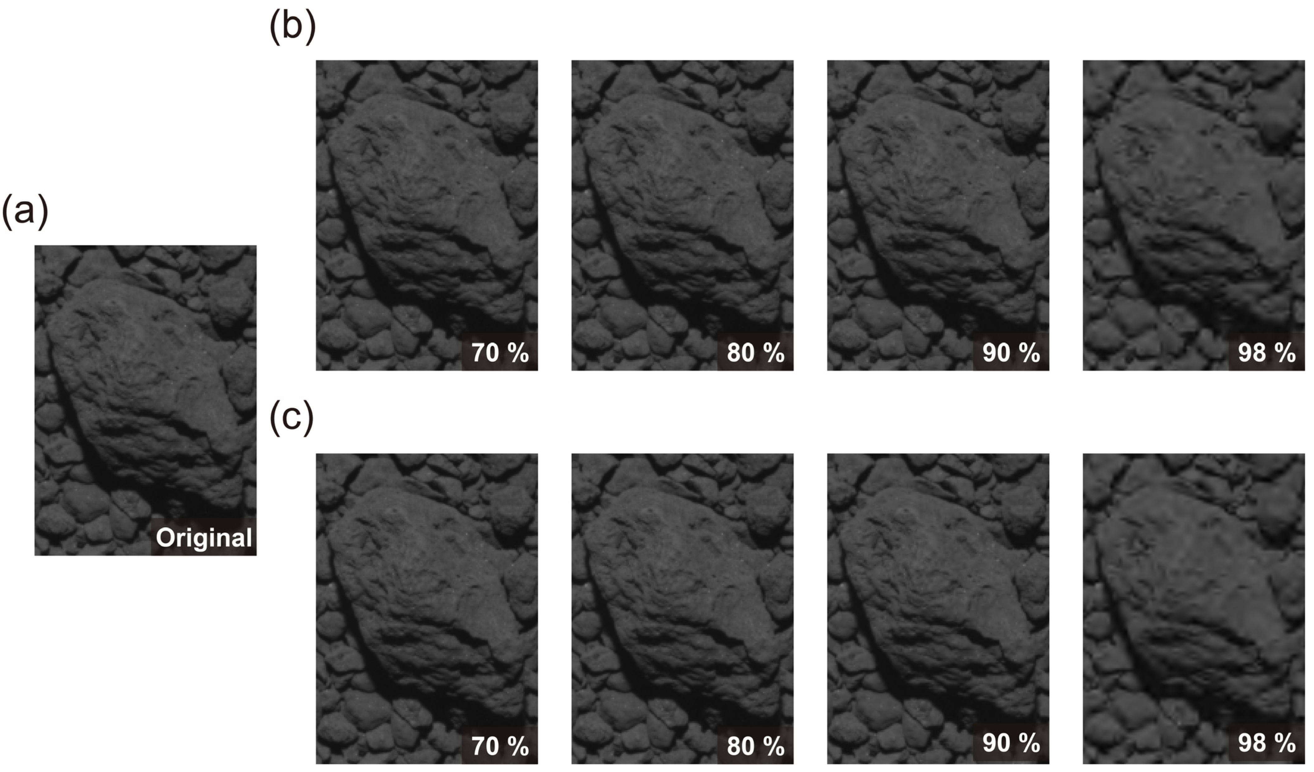
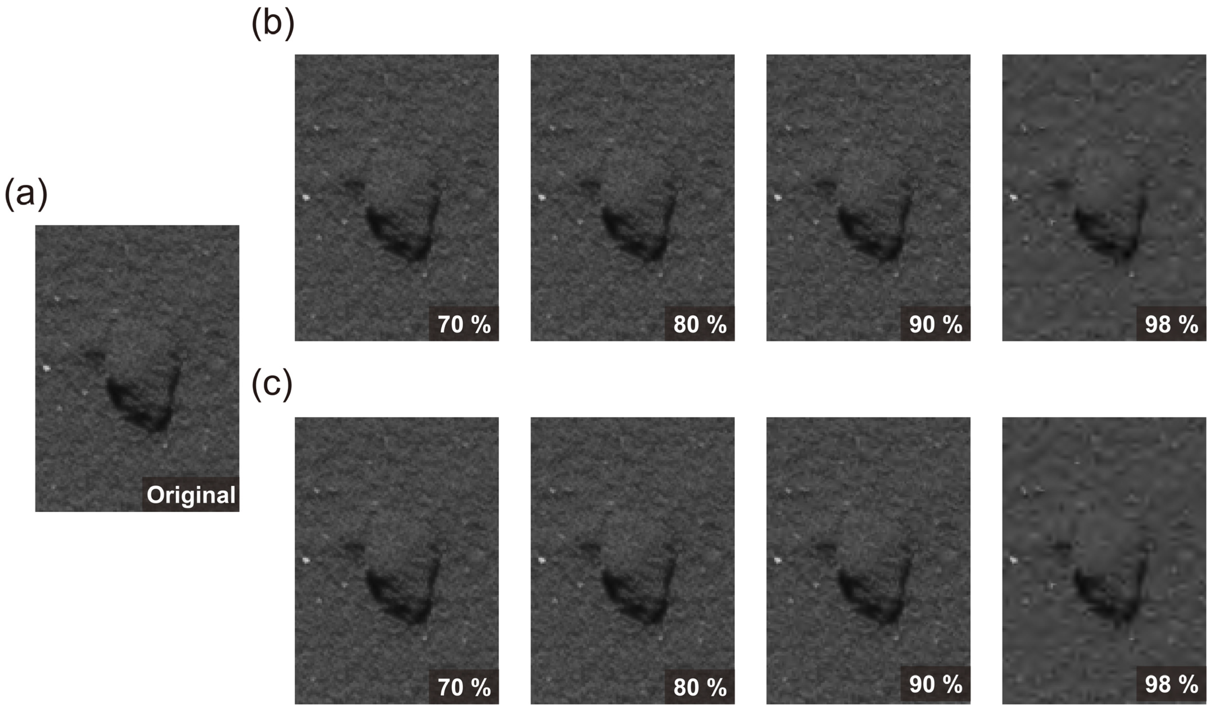
We compressed the simulated images of the rough and smooth surfaces, employing different compression ratios using the two algorithms, CCSDS with float- and integer-point DWT (Figure 6 and Figure 7). Basically, the difference in image compression performance between the two algorithms is limited. In terms of processing speed, ~0.18 sec. was required for the rough surface simulated image and ~0.71 sec. for the smooth surface simulated image, consistently across both algorithms. Moreover, visual changes or distortions in simulated images are not distinctly noticeable until the compression ratio reaches 98%, and this result is consistently observed in both algorithms (Figure 6 and Figure 7).
The image quality evaluation performed using PSNR also demonstrates that the difference in distortion levels between CCSDS with float- and integer-point DWT is considerably limited (Figure 8). However, our quantitative analysis also reveals that image quality can decrease at varying rates as the compression ratio increases, depending on the surface characteristics depicted in the images (i.e., rough vs. smooth surfaces). Our result shows that simulated images of the smooth surface can be significantly affected by image compression even at lower compression ratios, whereas simulated images of the rough surface exhibit fewer distortions even at higher compression ratios, which suggests that the difference in surface roughness can be a more significant factor for the distortion due to image compression, rather than the difference in compression algorithms. Likewise, this result reflects the data processing performed using DWT.
Images inherently consist of both high-frequency and low-frequency structures. High-frequency structures correspond to details and textures in images, while lower-frequency structures represent broader and more gradual changes in an image, such as variations in brightness. In the CCSDS with the DWT, the wavelet coefficients representing the high-frequency structures are more aggressively quantized or truncated, especially at higher compression ratios. Consequently, these high-frequency components are more susceptible to distortion than the low-frequency ones. Figure 6 and Figure 7 also show this effect, where small topographic features and textures, which constitute the highest-frequency structures in our images, are highly distorted by image compression. Essentially, the simulated images for the smooth surface contain more information related to such small topographic features (high-frequency structures) compared to the simulated images for the rough surface. This ratio means the former is more susceptible to image compression at the same compression ratio.
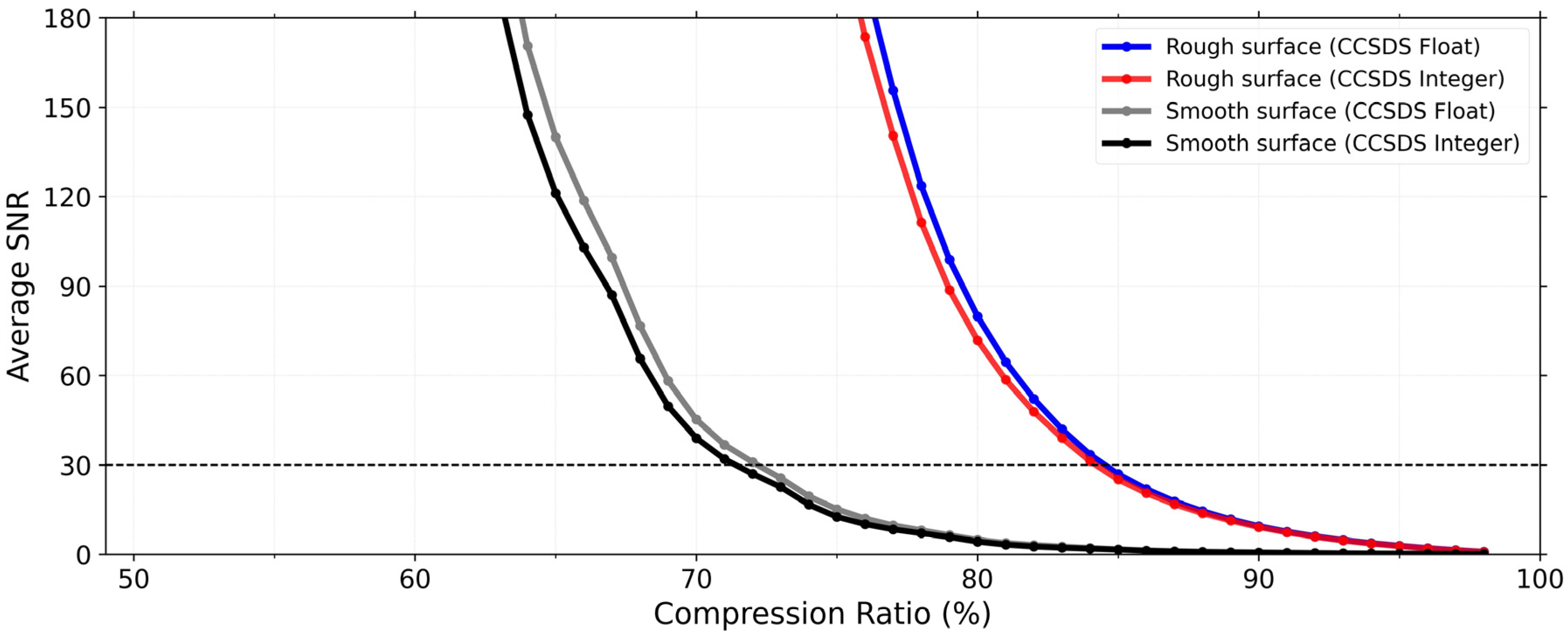
Our analysis using SNR (Figure 9) also shows a consistent result, where the difference in the loss of image quality between the two compression algorithms is minimal and the simulated images for the smooth surface are more susceptible to image compression, compared to the simulated images for the rough surface. In the MMX mission, the OROCHI is mainly planned to be used to obtain high-resolution images of Phobos’s surface, and these images will be used to observe detailed topographies, generating the local DTMs. Kameda et al. [44] set the performance requirement of the OROCHI as SNR > 30 for an effective observation of Phobos’s surface and selection of the landing sites. To fulfill this requirement across all images, the compression ratio should be 70% or lower (Figure 9). Furthermore, our image quality assessment using SSIM (Figure 10) also shows that, if the compression ratio is 70% or lower, quality loss remains constrained across all images. With such compression ratios, we expect significant scientific information to be maintained. Therefore, we recommend compression ratios of 70% or lower to reduce the data volume and simultaneously retain important scientific information in the MMX mission.

4. Discussion

4.1. Effect of Image Compression on the Accuracy of Generating Local DTMs

With a compression ratio of 70%, we analyzed whether local DTMs contain critical errors (that is, over 40 cm altitude errors) to find safe landing sites for the MMX mission. We compared local DTMs generated from compressed images (compressed model) with the model generated from uncompressed images (original model). The error calculations were performed using CloudCompare (ver. 2.11.2), a public 3D point cloud and mesh-processing software. In the model comparison, we first accurately registered the dense point cloud of the compressed models to that of the original model by minimizing the distances between each point. Then, we computed those distances and recorded them as errors.
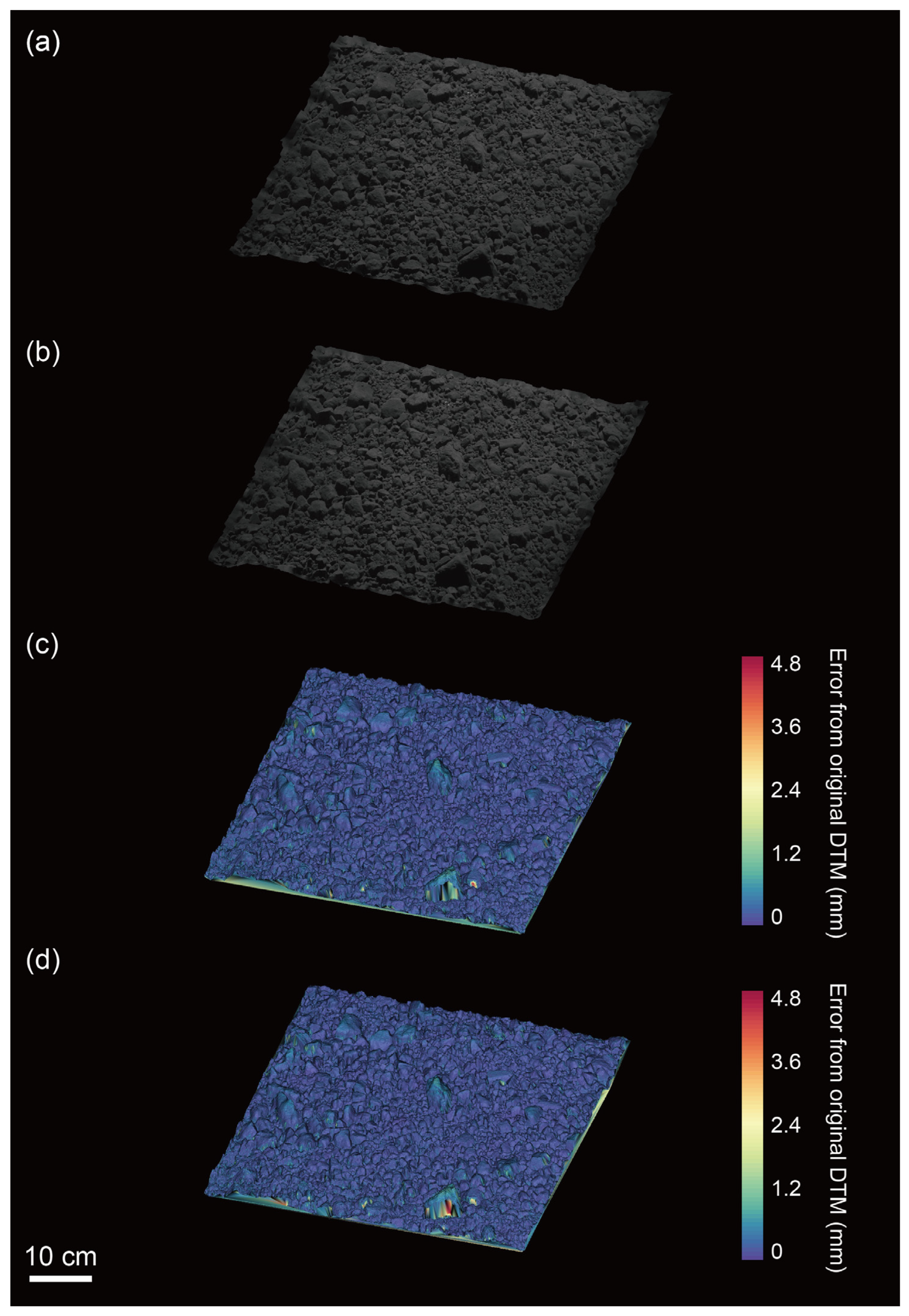
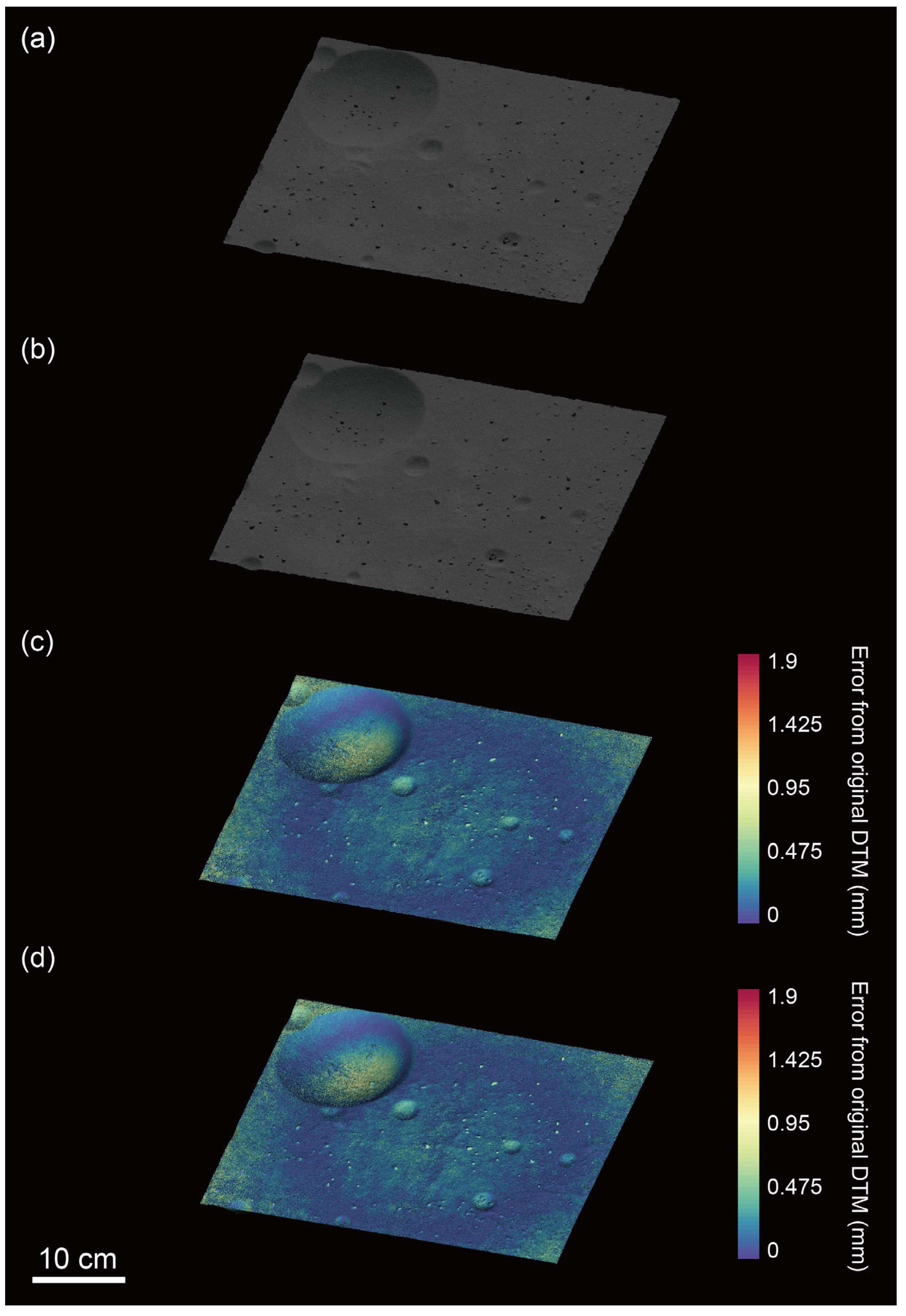
Figure 11 shows the compressed model for the rough surface, generated by 70% compressed images using CCSDS with float- and integer-point DWT. The models were each generated within a 2% difference in the number of dense points and meshes from the original model. Figure 12 represents the result of the smooth surface, with models generated with 3% differences in the number of dense points and meshes compared to those of the original. These results show that the qualities of the model generated are maintained, even when we used 70% compressed images.
Figure 11 and Figure 12 also show the errors of the compressed models from the original models. We showed that the compressed models for the rough surface could be generated with errors of 0.210 ± 0.145 mm (CCSDS with float-point DWT) and 0.208 ± 0.146 mm (CCSDS integer-point DWT), respectively. For the smooth surface, however, we could generate the models with errors of 0.205 ± 0.147 mm (CCSDS with float-point DWT) and 0.200 ± 0.145 mm (CCSDS integer-point DWT), respectively. In particular, the side with tall rock particles or the floors of the circular depressions tended to exhibit greater errors (partly due to inadequate imaging), resulting in a reduced number of dense points generated by the SfM.
In the MMX mission, the equatorial region (i.e., latitude 30 ° ) of Phobos is planned to be primarily observed from the orbit named at QSO, which is approximately 20 km away from the surface, to reveal detailed topography and surface compositions and identify the best landing sites. Assuming the spacecraft typically obtains images with a resolution of ~12 cm/pixel using the TENGOO [20], which is sufficient to observe >20 cm-sized hazardous rock particles, and scaling our image up, the 1 mm errors in our analysis can be equivalent to ~31.7 cm errors for the rough surface and ~107 cm errors for the smooth surface on Phobos. These errors are based on our image resolutions of 0.379 mm/pixel for the rough surface and 0.112 mm/pix for the smooth surface. In this case, for the rough surface, the errors are equivalent to 6.66 ± 4.60 cm (CCSDS with float-point DWT) and 6.59 ± 4.63 cm (CCSDS integer-point DWT), respectively. On the other hand, for the smooth surface, the errors are equivalent to 21.9 ± 15.7 cm (CCSDS with float-point DWT) and 21.4 ± 15.5 cm (CCSDS with integer-point DWT), respectively. This result means that local DTMs generated from compressed images with a compression ratio lower than 70% are expected not to include an error of the altitude larger than 40 cm, regardless of the surface roughness on Phobos. This situation is ideal for determining safe landing and sampling sites on the surface of Phobos. Therefore, we can expect that the compression ratio can be increased as high as 70% in the MMX mission, ensuring the safety of the spacecraft.
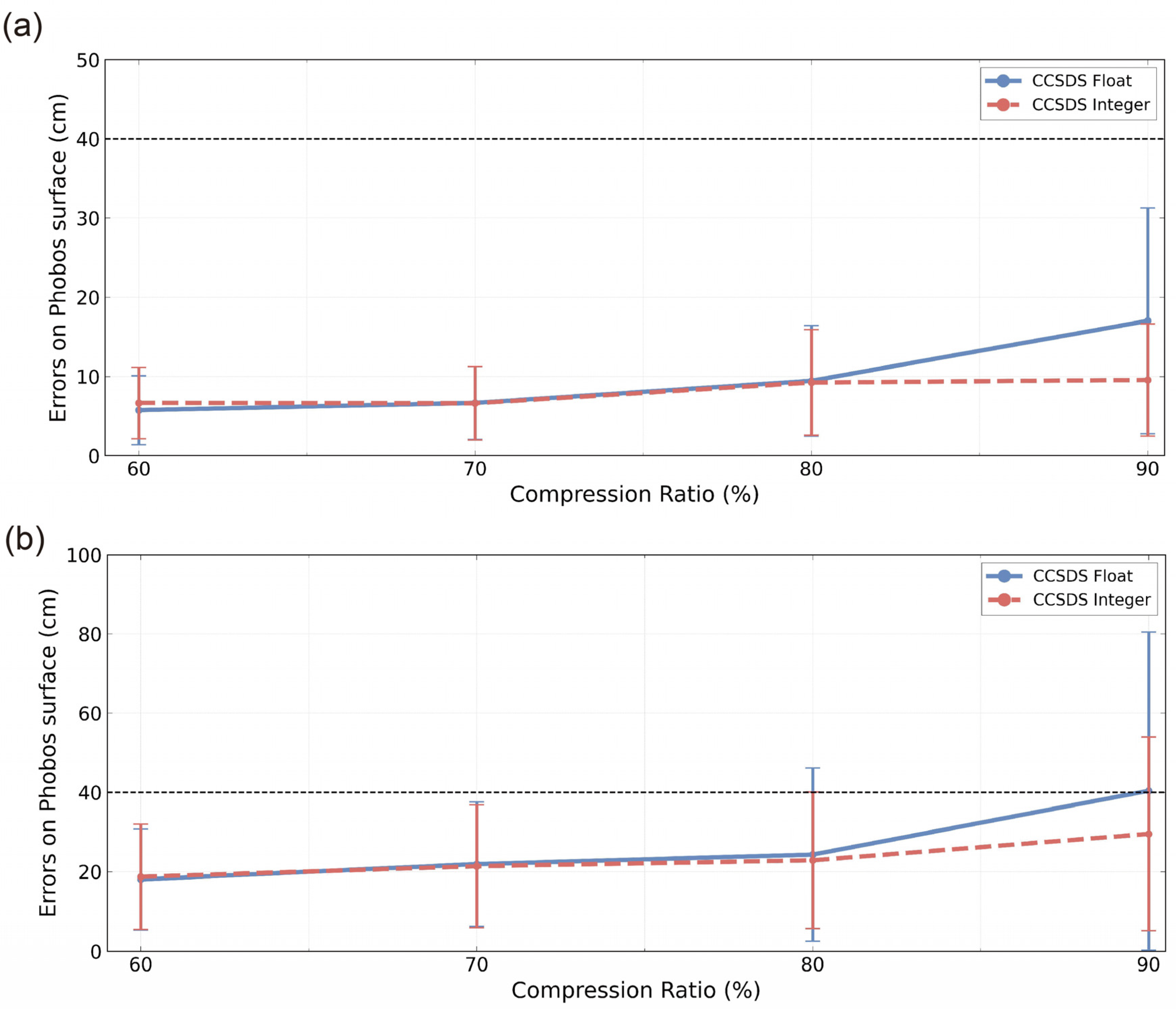
Furthermore, we generated local DTMs using images processed with compression ratios of 60%, 80%, and 90%, to evaluate the feasibility of our recommended compression ratio of 70%. Figure 13a shows the result of an error assessment for the local DTMs of the rough surface, while Figure 13b represents the result for the local DTMs of the smooth surface. Overall, we quantitatively show that the local DTMs for the smooth surface contain larger errors compared to the models for the rough surface, which is consistent with our result of image quality assessment (Section 3.2), indicating that the simulated images for the smooth surface are more susceptible to image compression. For the rough surface, we can generate local DTMs with errors smaller than 40 cm on Phobos’s surface, using images compressed with these four different compression ratios. However, for the smooth surface, the local DTMs can contain errors larger than 40 cm on Phobos’s surface, if the compression ratio is larger than 70%. This result strongly supports the idea that the compression ratio should be 70% or lower, to avoid any critical loss of scientific information especially for selecting the best landing sites, and at the same time to effectively reduce image data volume transmitted to the ground. Note that for both rough and smooth surfaces, the difference in errors of generating local DTMs using CCSDS with float- and integer-point DWT is minimal and these errors fall within the error range of other algorithms. Consequently, we conclude that the compression performances of the two algorithms do not differ significantly, which is consistent with the result from our quantitative analysis of image quality by PSNR, SNR, and SSIM discussed in Section 3.2.

4.2. Implications for the Observation in the MMX Mission

Given the nominal image resolution from the QSO (~12 cm/pix), the image size of the TENGOO ( 3296 × 2472 pixels), and the area of the equatorial region (latitude 30 ° ) of Phobos ( ~ 936   k m 2 ), more than ~3820 images (with >50% overlapping areas in each image for detailed analysis, including DTM reconstruction) are thought necessary to reveal detailed topography on Phobos for landing site selection. Transmitting all of those images would require ~180 days (~6.0 months), but such a duration can be shrunk into ~54 days (~1.8 months) using the compression ratio of 70%. This timescale is preferable for the landing site selection phase, currently planned to last approximately six months. Even so, downlink time for the TENGOO will be further constrained by several factors such as uplink communications, downlink of other science instruments onboard the MMX spacecraft, and availability of deep space communication facilities on the ground.
Note that the best compression ratio could change depending on various factors. These include differences in target image parameters such as image size, bit depth, and brightness/contrast. Also, the nature of the target surface, including the presence of fewer/more geological characteristics like craters, boulders (rocks), as well as varying albedo patterns, can play a crucial role. Furthermore, other criteria with varying acceptable local DTM errors and/or other compression algorithms can lead to a different optimal compression ratio. Therefore, determining the best compression ratio for each critical phase in future deep space exploration missions may require different or appropriate methods/criteria. This matter could be a topic for future research.

5. Conclusions

Low downlink rates can be one of the greatest limiting factors for deep space exploration missions, including the MMX mission. We thus prepared simulated images of Phobos using rough and smooth surfaces in a laboratory. We subsequently compressed those images using the CCSDS with float- and integer-point DWT candidate algorithms that can be used in the MMX mission. The image quality assessment performed by PSNR, SNR, and SSIM shows that the difference in the compression performances between the two algorithms is substantially limited. Notably, the loss of image quality can differ depending on the roughness of the surface in images. But, such loss of quality remains constrained if we compress images with a compression ratio lower than or equal to 70%.
We further compared the local DTMs generated using compressed and uncompressed images. Our result shows that the models can be generated with altitude errors smaller than 40 cm on Phobos, even if we compress images with a compression ratio of 70%. Thus, we can expect that the compression ratio can be increased as high as 70% in the MMX mission. Using this compression ratio, we can reduce the data volume without losing important scientific information. This approach can be significantly effective in the MMX mission, particularly during the landing site selection phase, which is one of the most crucial parts of this mission.

Author Contributions

Conceptualization, Y.S. and H.M.; methodology, Y.S., H.M. and S.K.; software, Y.S.; validation, Y.S. and H.M.; formal analysis, Y.S.; investigation, Y.S., H.M. and S.K.; resources, H.M. and S.K.; data curation, Y.S., H.M. and S.K.; writing—original draft preparation, Y.S. and H.M.; writing—review and editing, Y.S., H.M. and S.K.; visualization, Y.S.; supervision, H.M.; project administration, H.M. All authors have read and agreed to the published version of the manuscript.

Funding

This research was supported by JSPS KAKENHI Grant Numbers JP21J21798, JP23H00279.

Data Availability Statement

The source code for the compression algorithm, CCSDS is available at http://hyperspectral.unl.edu/download.htm (accessed on 18 November 2023). The data presented in this study will be openly available in FigShare at https://doi.org/10.6084/m9.figshare.24251320 (accessed on 18 November 2023).

Conflicts of Interest

The authors declare no conflict of interest. The funders had no role in the design of the study; in the collection, analyses, or interpretation of data; in the writing of the manuscript; or in the decision to publish the results.

References

  1. Saito, J.; Miyamoto, H.; Nakamura, R.; Ishiguro, M.; Michikami, T.; Nakamura, A.M.; Demura, H.; Sasaki, S.; Hirata, N.; Honda, C.; et al. Detailed images of asteroid 25143 Itokawa from Hayabusa. Science 2006, 312, 1341–1344. [Google Scholar] [CrossRef]
  2. Watanabe, S.; Tsuda, Y.; Yoshikawa, M.; Tanaka, S.; Saiki, T.; Nakazawa, S. Hayabusa2 Mission Overview. Space Sci. Rev. 2017, 208, 3–16. [Google Scholar] [CrossRef]
  3. Glassmeier, K.H.; Boehnhardt, H.; Koschny, D.; Kuhrt, E.; Richter, I. The ROSETTA Mission: Flying towards the origin of the solar system. Space Sci. Rev. 2007, 128, 1–21. [Google Scholar] [CrossRef]
  4. Lauretta, D.S.; Balram-Knutson, S.S.; Beshore, E.; Boynton, W.V.; d’Aubigny, C.D.; DellaGiustina, D.N.; Enos, H.L.; Golish, D.R.; Hergenrother, C.W.; Howell, E.S.; et al. OSIRIS-REx: Sample Return from Asteroid (101955) Bennu. Space Sci. Rev. 2017, 212, 925–984. [Google Scholar] [CrossRef]
  5. Lord, P.; Tilley, S.; Oh, D.Y.; Goebel, D.; Polanskey, C.; Snyder, S.; Carr, G.; Collins, S.M.; Lantoine, G.; Landau, D.; et al. Psyche: Journey to a Metal World. In Proceedings of the IEEE Aerospace Conference, Big Sky, MT, USA, 4–11 March 2017. [Google Scholar]
  6. Lorenz, R.D.; MacKenzie, S.M.; Neish, C.D.; Gall, A.L.; Turtle, E.P.; Barnes, J.W.; Trainer, M.G.; Werynski, A.; Hedgepeth, J.; Karkoschka, E. Selection and Characteristics of the Dragonfly Landing Site near Selk Crater, Titan. Planet. Sci. J. 2021, 2, 24. [Google Scholar] [CrossRef]
  7. Levison, H.F.; Olkin, C.B.; Noll, K.S.; Marchi, S.; Bell, J.; Bierhaus, E.; Binzel, R.; Bottke, W.; Britt, D.; Brown, M.; et al. Lucy Mission to the Trojan Asteroids: Science Goals. Planet. Sci. J. 2021, 2, 171. [Google Scholar] [CrossRef]
  8. Michel, P.; Kuppers, M.; Bagatin, A.C.; Carry, B.; Charnoz, S.; de Leon, J.; Fitzsimmons, A.; Gordo, P.; Green, S.F.; Herique, A.; et al. The ESA Hera Mission: Detailed Characterization of the DART Impact Outcome and of the Binary Asteroid (65803) Didymos. Planet. Sci. J. 2022, 3, 160. [Google Scholar] [CrossRef]
  9. Kuramoto, K.; Kawakatsu, Y.; Fujimoto, M.; Araya, A.; Barucci, M.A.; Genda, H.; Hirata, N.; Ikeda, H.; Imamura, T.; Helbert, J.; et al. Martian moons exploration MMX: Sample return mission to Phobos elucidating formation processes of habitable planets. Earth Planets Space 2022, 74, 12. [Google Scholar] [CrossRef]
  10. Pollack, J.B.; Veverka, J.; Pang, K.; Colburn, D.; Lane, A.L.; Ajello, J.M. Multicolor observations of Phobos with the Viking Lander cameras: Evidence for a carbonaceous chondritic composition. Science 1978, 199, 66–69. [Google Scholar] [CrossRef]
  11. Hartmann, W.K. Additional Evidence about An Early Intense Flux of C-asteroids and The Origin of Phobos. Icarus 1990, 87, 236–240. [Google Scholar] [CrossRef]
  12. Pajola, M.; Lazzarin, M.; Ore, C.M.D.; Cruikshank, D.P.; Roush, T.L.; Magrin, S.; Bertini, I.; La Forgia, F.; Barbieri, C. Phobos as A D-type Captured Asteroid, Spectral Modeling from 0.25 to 4.0 μm. Astrophys. J. 2013, 777, 127. [Google Scholar] [CrossRef]
  13. Burns, J.A. Contradictory clues as to the origin of the Martian moons. In Mars; Kieffer, H.H., Jakosky, B.M., Snyder, C.W., Matthews, M.S., Eds.; University of Arizona Press: Tucson, AZ, USA, 1992; pp. 1283–1301. [Google Scholar]
  14. Citron, R.I.; Genda, H.; Ida, S. Formation of Phobos and Deimos via a giant impact. Icarus 2015, 252, 334–338. [Google Scholar] [CrossRef]
  15. Craddock, R.A. Are Phobos and Deimos the result of a giant impact? Icarus 2011, 211, 1150–1161. [Google Scholar] [CrossRef]
  16. Hyodo, R.; Genda, H.; Charnoz, S.; Rosenblatt, P. On the Impact Origin of Phobos and Deimos. I. Thermodynamic and Physical Aspects. Astrophys. J. 2017, 845, 125. [Google Scholar] [CrossRef]
  17. Hyodo, R.; Rosenblatt, P.; Genda, H.; Charnoz, S. On the Impact Origin of Phobos and Deimos. II. True Polar Wander and Disk Evolution. Astrophys. J. 2017, 851, 122. [Google Scholar] [CrossRef]
  18. Hyodo, R.; Genda, H.; Charnoz, S.; Pignatale, F.C.F.; Rosenblatt, P. On the Impact Origin of Phobos and Deimos. IV. Volatile Depletion. Astrophys. J. 2018, 860, 150. [Google Scholar] [CrossRef]
  19. Pignatale, F.C.; Charnoz, S.; Rosenblatt, P.; Hyodo, R.; Nakamura, T.; Genda, H. On the Impact Origin of Phobos and Deimos. III. Resulting Composition from Different Impactors. Astrophys. J. 2018, 853, 118. [Google Scholar] [CrossRef]
  20. Nakamura, T.; Ikeda, H.; Kouyama, T.; Nakagawa, H.; Kusano, H.; Senshu, H.; Kameda, S.; Matsumoto, K.; Gonzalez-Franquesa, F.; Ozaki, N.; et al. Science operation plan of Phobos and Deimos from the MMX spacecraft. Earth Planets Space 2021, 73, 227. [Google Scholar] [CrossRef]
  21. Willner, K.; Shi, X.; Oberst, J. Phobos’ shape and topography models. Planet. Space Sci. 2014, 102, 51–59. [Google Scholar] [CrossRef]
  22. Asphaug, E.; Melosh, H.J. The Stickney impact of Phobos: A dynamical model. Icarus 1993, 101, 144–164. [Google Scholar] [CrossRef]
  23. Basilevsky, A.T.; Lorenz, C.A.; Shingareva, T.V.; Head, J.W.; Ramsley, K.R.; Zubarev, A.E. The surface geology and geomorphology of Phobos. Planet. Space Sci. 2014, 102, 95–118. [Google Scholar] [CrossRef]
  24. Karachevtseva, I.P.; Oberst, J.; Zubarev, A.E.; Nadezhdina, I.E.; Kokhanov, A.A.; Garov, A.S.; Uchaev, D.V.; Malinnikov, V.A.; Klimkin, N.D. The Phobos information system. Planet. Space Sci. 2014, 102, 74–85. [Google Scholar] [CrossRef]
  25. Salamuniccar, G.; Loncaric, S.; Pina, P.; Bandeira, L.; Saraiva, J. Integrated Crater Detection Algorithm and Systematic Cataloging of Phobos Craters. In Proceedings of the 7th International Symposium on Image and Signal Processing and Analysis (Ispa 2011), Dubrovnik, Croatia, 4–6 September 2011; pp. 591–596. [Google Scholar]
  26. Salamuniccar, G.; Loncaric, S.; Pina, P.; Bandeira, L.; Saraiva, J. Integrated method for crater detection from topography and optical images and the new PH9224GT catalogue of Phobos impact craters. Adv. Space Res. 2014, 53, 1798–1809. [Google Scholar] [CrossRef]
  27. Schmedemann, N.; Michael, G.G.; Ivanov, B.A.; Murray, J.B.; Neukum, G. The age of Phobos and its largest crater, Stickney. Planet. Space Sci. 2014, 102, 152–163. [Google Scholar] [CrossRef]
  28. Thomas, P.C.; Veverka, J.; Sullivan, R.; Simonelli, D.P.; Malin, M.C.; Caplinger, M.; Hartmann, W.K.; James, P.B. Phobos: Regolith and ejecta blocks investigated with Mars Orbiter Camera images. J. Geophys. Res. Planets 2000, 105, 15091–15106. [Google Scholar] [CrossRef]
  29. Murray, J.B.; Heggie, D.C. Character and origin of Phobos’ grooves. Planet. Space Sci. 2014, 102, 119–143. [Google Scholar] [CrossRef]
  30. Wilson, L.; Head, J.W. Groove formation on Phobos: Testing the Stickney ejecta emplacement model for a subset of the groove population. Planet. Space Sci. 2015, 105, 26–42. [Google Scholar] [CrossRef]
  31. Thomas, P.; Veverka, J.; Bloom, A.; Duxbury, T. Grooves on Phobos—Their Distribution, Morphology and Possible Origin. J. Geophys. Res. 1979, 84, 8457–8477. [Google Scholar] [CrossRef]
  32. Andert, T.P.; Rosenblatt, P.; Patzold, M.; Hausler, B.; Dehant, V.; Tyler, G.L.; Marty, J.C. Precise mass determination and the nature of Phobos. Geophys. Res. Lett. 2010, 37, 4. [Google Scholar] [CrossRef]
  33. Ballouz, R.L.; Walsh, K.J.; Sanchez, P.; Holsapple, K.A.; Michel, P.; Scheeres, D.J.; Zhang, Y.; Richardson, D.C.; Barnouin, O.S.; Nolan, M.C.; et al. Modified granular impact force laws for the OSIRIS-REx touchdown on the surface of asteroid (101955) Bennu. Mon. Not. R. Astron. Soc. 2021, 507, 5087–5105. [Google Scholar] [CrossRef]
  34. Terui, F.; Ogawa, N.; Ono, G.; Yasuda, S.; Masuda, T.; Matsushima, K.; Saiki, T.; Tsuda, Y. Guidance, navigation, and control of Hayabusa2 touchdown operations. Astrodynamics 2020, 4, 393–409. [Google Scholar] [CrossRef]
  35. Walsh, K.J.; Ballouz, R.L.; Jawin, E.R.; Avdellidou, C.; Barnouin, O.S.; Bennett, C.A.; Bierhaus, E.B.; Bos, B.J.; Cambioni, S.; Connolly, H.C.; et al. Near-zero cohesion and loose packing of Bennu’s near subsurface revealed by spacecraft contact. Sci. Adv. 2022, 8, eabm6229. [Google Scholar] [CrossRef]
  36. Kawaguchi, J.I.; Fujiwara, A.; Uesugi, T. Hayabusa—Its technology and science accomplishment summary and Hayabusa-2. Acta Astronaut. 2008, 62, 639–647. [Google Scholar] [CrossRef]
  37. Yoshikawa, K.; Sawada, H.; Kikuchi, S.; Ogawa, N.; Mimasu, Y.; Ono, G.; Takei, Y.; Terui, F.; Saiki, T.; Yasuda, S.; et al. Modeling and analysis of Hayabusa2 touchdown. Astrodynamics 2020, 4, 119–135. [Google Scholar] [CrossRef]
  38. Takemura, T.; Miyamoto, H.; Hemmi, R.; Niihara, T.; Michel, P. Small-scale topographic irregularities on Phobos: Image and numerical analyses for MMX mission. Earth Planets Space 2021, 73, 213. [Google Scholar] [CrossRef]
  39. Pollack, J.B.; Born, G.H.; Smith, B.A.; Veverka, J.; Sagan, C.; Duxbury, T.C.; Milton, D.J.; Hartmann, W.K.; Noland, M. Mariner 9 Television Observations of Phobos and Deimos. Icarus 1972, 17, 394–407. [Google Scholar] [CrossRef]
  40. Veverka, J.; Duxbury, T.C. Viking observations of Phobos and Deimos: Preliminary results. J. Geophys. Res. 1977, 82, 4213–4223. [Google Scholar] [CrossRef]
  41. Witasse, O.; Duxbury, T.; Chicarro, A.; Altobelli, N.; Andert, T.; Aronica, A.; Barabash, S.; Bertaux, J.L.; Bibring, J.P.; Cardesin-Moinelo, A.; et al. Mars Express investigations of Phobos and Deimos. Planet. Space Sci. 2014, 102, 18–34. [Google Scholar] [CrossRef]
  42. Thomas, N.; Stelter, R.; Ivanov, A.; Bridges, N.T.; Herkenhoff, K.E.; McEwen, A.S. Spectral heterogeneity on Phobos and Deimos: HiRISE observations and comparisons to Mars Pathfinder results. Planet. Space Sci. 2011, 59, 1281–1292. [Google Scholar] [CrossRef]
  43. Amiri, H.E.S.; Brain, D.; Sharaf, O.; Withnell, P.; McGrath, M.; Alloghani, M.; Al Awadhi, M.; Al Dhafri, S.; Al Hamadi, O.; Al Matroushi, H.; et al. The Emirates Mars Mission. Space Sci. Rev. 2022, 218, 46. [Google Scholar] [CrossRef] [PubMed]
  44. Kameda, S.; Ozaki, M.; Enya, K.; Fuse, R.; Kouyama, T.; Sakatani, N.; Suzuki, H.; Osada, N.; Kato, H.; Miyamoto, H.; et al. Design of telescopic nadir imager for geomorphology (TENGOO) and observation of surface reflectance by optical chromatic imager (OROCHI) for the Martian Moons Exploration (MMX). Earth Planets Space 2021, 73, 218. [Google Scholar] [CrossRef]
  45. Ishiguro, M.; Nakamura, R.; Tholen, D.J.; Hirata, N.; Demura, H.; Nemoto, E.; Nakamura, A.M.; Higuchi, Y.; Sogame, A.; Yamamoto, A.; et al. The Hayabusa Spacecraft Asteroid Multi-band Imaging Camera (AMICA). Icarus 2010, 207, 714–731. [Google Scholar] [CrossRef]
  46. Kameda, S.; Suzuki, H.; Takamatsu, T.; Cho, Y.; Yasuda, T.; Yamada, M.; Sawada, H.; Honda, R.; Morota, T.; Honda, C.; et al. Preflight Calibration Test Results for Optical Navigation Camera Telescope (ONC-T) Onboard the Hayabusa2 Spacecraft. Space Sci. Rev. 2017, 208, 17–31. [Google Scholar] [CrossRef]
  47. Rizk, B.; d’Aubigny, C.D.; Golish, D.; Fellows, C.; Merrill, C.; Smith, P.; Walker, M.S.; Hendershot, J.E.; Hancock, J.; Bailey, S.H.; et al. OCAMS: The OSIRIS-REx Camera Suite. Space Sci. Rev. 2018, 214, 1–55. [Google Scholar] [CrossRef]
  48. Re, C.; Simioni, E.; Cremonese, G.; Roncella, R.; Forlani, G.; Langevin, Y.; Da Deppo, V.; Naletto, G.; Salemi, G. Effects of image compression and illumination on digital terrain models for the stereo camera of the BepiColombo mission. Planet. Space Sci. 2017, 136, 1–14. [Google Scholar] [CrossRef]
  49. Shimizu, Y.; Kamiyoshihara, H.; Niihara, T.; Miyamoto, H. Experimental Study to Determine the Best Compression Ratio of High-Resolution Images of Small Bodies for the Martian Moons eXploration Mission. Trans. Jpn. Soc. Aeronaut. Space Sci. 2020, 63, 212–221. [Google Scholar] [CrossRef]
  50. Miyamoto, H.; Niihara, T.; Wada, K.; Ogawa, K.; Senshu, H.; Michel, P.; Kikuchi, H.; Hemmi, R.; Nakamura, T.; Nakamura, A.M.; et al. Surface environment of Phobos and Phobos simulant UTPS. Earth Planets Space 2021, 73, 214. [Google Scholar] [CrossRef]
  51. Wang, Z.; Bovik, A.C.; Sheikh, H.R.; Simoncelli, E.P. Image quality assessment: From error visibility to structural similarity. IEEE Trans. Image Process. 2004, 13, 600–612. [Google Scholar] [CrossRef]
  52. McEwen, A.S.; Eliason, E.M.; Bergstrom, J.W.; Bridges, N.T.; Hansen, C.J.; Delamere, W.A.; Grant, J.A.; Gulick, V.C.; Herkenhoff, K.E.; Keszthelyi, L.; et al. Mars Reconnaissance Orbiter’s High Resolution Imaging Science Experiment (HiRISE). J. Geophys. Res. Planets 2007, 112, 40. [Google Scholar] [CrossRef]
  53. Gaskell, R.W.; Barnouin-Jha, O.S.; Scheeres, D.J.; Konopliv, A.S.; Mukai, T.; Abe, S.; Saito, J.; Ishiguro, M.; Kubota, T.; Hashimoto, T.; et al. Characterizing and navigating small bodies with imaging data. Meteorit. Planet. Sci. 2008, 43, 1049–1061. [Google Scholar] [CrossRef]
  54. Watanabe, S.; Hirabayashi, M.; Hirata, N.; Noguchi, R.; Shimaki, Y.; Ikeda, H.; Tatsumi, E.; Yoshikawa, M.; Kikuchi, S.; Yabuta, H.; et al. Hayabusa2 arrives at the carbonaceous asteroid 162173 Ryugu-A spinning top-shaped rubble pile. Science 2019, 364, 268–272. [Google Scholar] [CrossRef] [PubMed]
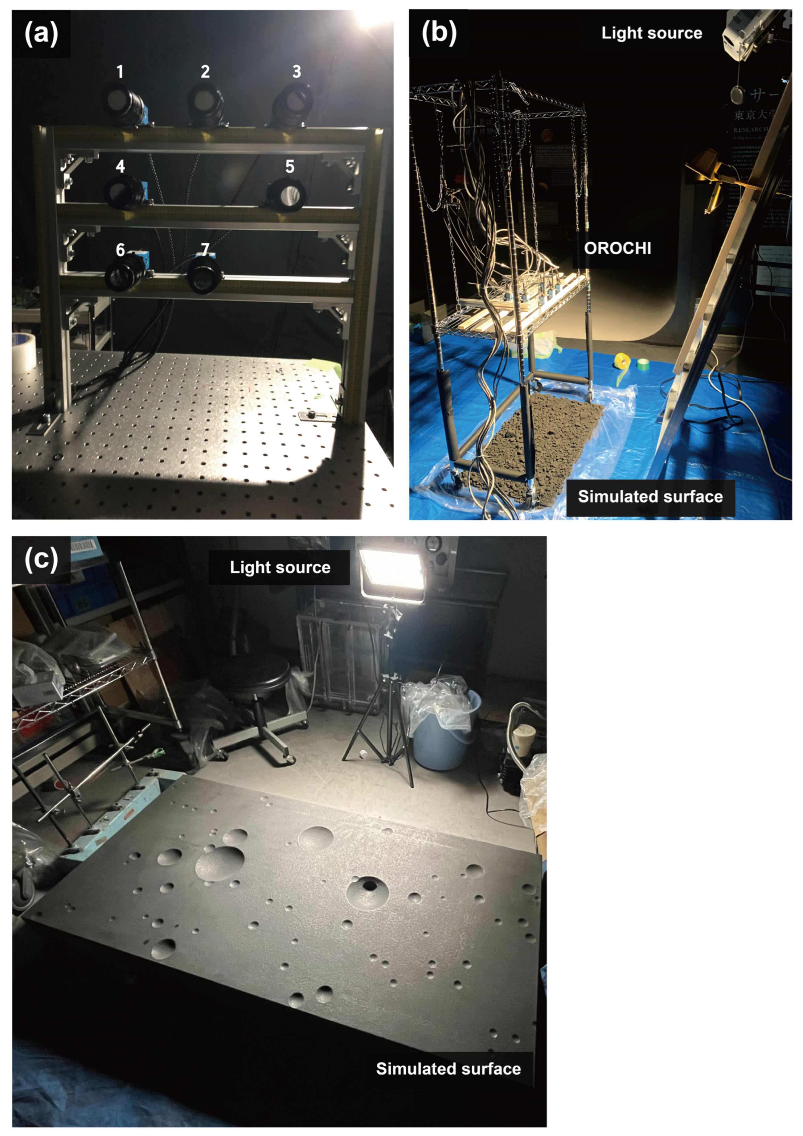
Figure 1. OROCHI simulator and experimental setups. (a) OROCHI simulator. Each number represents an imager with the corresponding band-pass filters: 1: 390 nm, 2: 480 nm, 3: 550 nm, 4: 650 nm, 5: 700 nm, 6: 800 nm, 7: 950 nm. (b) Experimental setup for simulated Phobos images with a rough surface. The OROCHI simulator model was fixed to a movable frame, enabling the capture of images of the same region from different camera positions. (c) Experimental setup for simulated Phobos images with a smooth surface. For a simulated surface, we used a foundation with circular depressions, resembling the actual cratered Phobos surface.
Remotesensing 15 05500 g001
Figure 2. Examples of the simulated images for the rough surface. The image size is 1920 × 1200 pixels and the color space is grayscale. The spatial resolution is 0.379 mm/pix. Note that dark regions surrounded by white lines represent image masks, which show ignored regions while generating the local DTMs. A total of 10 simulated images were prepared for the rough surface.
Remotesensing 15 05500 g002
Figure 3. Examples of the simulated images for the smooth surface. The image size is 3296 × 2472 pixels, and they are expressed in grayscale. The average spatial resolution is 0.112 mm/pix. Dark regions represent image masks, which show ignored regions while generating the local DTMs. A total of 44 simulated images were prepared for the smooth surface.
Remotesensing 15 05500 g003
Figure 4. Local DTMs of the rough and smooth surfaces (a) Local DTM for the rough surface. The model is composed of 3,826,280 points and 2,309,668 facets. (b) Local DTM for the smooth surface. The model has 13,265,901 points, resulting in 10,012,252 facets. Those two models express simulated surfaces in a three-dimensional space with a substantially high resolution.
Remotesensing 15 05500 g004
Figure 5. Elevations of the local DTMs for the rough and smooth simulated surfaces. (a) Elevation of the model for the rough surface. The standard deviation of the elevation is 19.2 mm. (b) Elevation of the model for the smooth surface. The standard deviation of the elevation is 8.99 mm, which represents the smoother surface of the model, compared to the model for the rough surface.
Remotesensing 15 05500 g005
Figure 6. Image compression effects on the simulated image of the rough surface. (a) Original image. (b) Images compressed with CCSDS with float-point DWT. (c) Images compressed with CCSDS with integer-point DWT. The difference in the distortion level of the two different compression algorithms is minimal. From this simple visual analysis, distortions caused by image compression are not readily apparent until the compression ratio reaches 98%. Those distortions are basically found on small roughness or textures, which correspond to high-frequency structures in image processing using DWT.
Remotesensing 15 05500 g006
Figure 7. Image compression effects on the simulated image of the smooth surface. (a) Original image. (b) Images compressed with CCSDS with float-point DWT. (c) Images compressed with CCSDS with integer-point DWT. The difference in the distortion level of the two different compression algorithms is limited. Also, from this simple visual analysis, image distortion caused by compression cannot be confirmed clearly until the compression ratio reaches 98%. Such distortions, overall, exist in small roughness or textures, which correspond to high-frequency structures in the image-processing using DWT.
Remotesensing 15 05500 g007
Figure 8. Image quality assessment using PSNR. The differences in the loss of image quality between the two algorithms, CCSDS with float- and integer-point DWT, are consistently limited, in both simulated images for the rough and smooth surfaces. With the same compression ratio, the simulated images for the smooth surface have lower image qualities, compared to the simulated images for the rough surface. This result represents the characteristic of image processing using DWT, where small roughness or textures (high-frequency structures) are more affected by image compression.
Remotesensing 15 05500 g008
Figure 9. Image quality assessment using SNR. Similar to the assessment by PSNR, the difference in the compression performances between the CCSDS with float- and integer-point DWT is minimal, and the simulated images for the smooth surface have lower image qualities. The black dotted line represents SNR = 30, which is a performance requirement determined by Kameda et al. [44] to conduct an effective landing site selection on the surface of Phobos. If the compression ratio is 70% or lower, SNR is expected to be larger than 30, which is preferable to perform the landing site selection in the MMX mission.
Remotesensing 15 05500 g009
Figure 10. Image quality assessment using SSIM. The difference in the image quality decrease between CCSDS with float- and integer-point DWT is consistently minimal across all compression ratios, which is consistent with the assessments using PSNR and SNR. Our quantitative analysis shows that the quality of simulated images for the smooth surface is more susceptible to image compression, even at lower compression ratios, compared to those for the rough surface, which is also consistent with the results from the analyses performed by PSNR and SNR. Furthermore, we reveal that compression ratios equal to or lower than 70% exhibit limited loss of image quality.
Remotesensing 15 05500 g010
Figure 11. Compressed models for the rough surface and their error analysis. The error analysis shows the error of compressed models from the original models. (a) Local DTM generated by using compressed images processed by CCSDS with float-point DWT. The model is composed of 3,872,302 dense points and 2,317,660 meshes. (b) Local DTM generated by using compressed images processed by CCSDS with integer-point DWT. The model is composed of 3,873,461 dense points and 2,303,035 meshes. (c) The error analysis of the model shown in (a). The error of this model is 0.210 ± 0.145 mm, equivalent to the error of 6.66 ± 4.60 cm on Phobos. (d) The error analysis of the model shown in (b). The error of this model is 0.208 ± 0.146 mm, equivalent to the error of 6.59 ± 4.63 cm on Phobos. Both analyses show that the compressed models can be generated within 2% error of the number of dense points and meshes from the original model. Further, the altitude errors can be smaller than 40 cm on Phobos, which means that 70% compressed images effectively reduce file sizes without losing important scientific information, especially for determining safe landing sites.
Remotesensing 15 05500 g011
Figure 12. Compressed models for the smooth surface and their error analysis. The error analysis shows the error of compressed models from the original models. (a) Local DTM generated by using compressed images processed by CCSDS with float-point DWT. The model is composed of 13,074,155 dense points and 9,848,738 meshes. (b) Local DTM generated by using compressed images processed by CCSDS with integer-point DWT. The model is composed of 12,964,085 dense points and 9,902,717 meshes. (c) The error analysis of the model shown in (a). The error of this model is 0.205 ± 0.147 mm, equivalent to the error of 21.9 ± 15.7 cm on Phobos. (d) The error analysis of the model shown in (b). The error of this model is 0.200 ± 0.145 mm, which is equivalent to the error of 21.4 ± 15.5 cm on Phobos. Both analyses show that the compressed models can be generated within 3% errors of the number of dense points and meshes from the original model. Meanwhile, the altitude errors can be smaller than 40 cm on Phobos. As such, 70% compressed images effectively reduce file sizes without losing important scientific information, especially to determine the safe landing sites. Note that the circular error patterns observed in (c), (d) are related to the difference in the estimated camera parameters (i.e., focal length and radial distortion parameters) between the original and compressed models.
Remotesensing 15 05500 g012
Figure 13. Error assessment for the local DTMs of the rough and smooth simulated surfaces of Phobos. The errors represent the distances between the compressed models and the original model. The error bars show the standard deviation of the errors. The black dotted line indicates the error of 40 cm on Phobos’s surface, which can be critical for the safety of spacecraft when we select suitable landing sites in the MMX mission. (a) Error assessment for the local DTMs of the smooth surface. Across four compression ratios, the local DTMs can be generated within the error of 40 cm. (b) Error assessment for the local DTMs of the rough surface. When the compression ratio becomes larger than 70%, the local DTMs can contain the critical errors larger than 40 cm, which is not preferable for the landing site selection in the MMX mission.
Remotesensing 15 05500 g013
Table 1. Parameters used to generate local DTMs with high accuracy using Metashape.
ProcessParameterSettingComments
Align photosAccuracyHighestThe program aligns photos with the highest accuracy.
Generic preselectionOnThe program makes low-resolution images and finds key points in order to decrease the process time.
Reference preselectionOnThe program generates a sparse point cloud by using the camera coordinates information input a priori.
Key point limit0Key points will be generated without the limitation of the number of points.
Tie point limit0Tie points will be generated without the limitation of the number of points.
Adaptive camera model fittingOffWhen this parameter is set to be On, the camera parameters for fitting the distortion of the lenses will be determined, which is not necessary in this research.
Build dense cloudAccuracyUltra highThe dense cloud is generated with the highest accuracy.
Depth filteringMildHow aggressively the program filters outliers obtained from the depth computation. “Mild” is recommended.
Build meshSurface typeArbitrary (3D)“Arbitrary (3D)” means that the program generates a closed 3D shape model without any holes.
SourceDepth mapsThe program generates the mesh using all the information from the input images including assumed depth maps, which is recommended to use.
QualityUltra highThe mesh is generated with the highest accuracy.
Face count100,000,000We set the parameter large enough in order to generate meshes without any limitations of the number or meshes.
Disclaimer/Publisher’s Note: The statements, opinions and data contained in all publications are solely those of the individual author(s) and contributor(s) and not of MDPI and/or the editor(s). MDPI and/or the editor(s) disclaim responsibility for any injury to people or property resulting from any ideas, methods, instructions or products referred to in the content.