Abstract
Spoofing interference poses a significant challenge to the Global Navigation Satellite System (GNSS). To effectively combat intermediate spoofing signals, this paper presents an enhanced spoofing detection method based on abnormal energy of the quadrature (Q) channel correlators. The detailed principle of this detection method is introduced based on the received signal model under spoofing attack. The normalization parameter used in this method was the estimation of the noise floor. The performance of the proposed Q energy detector is validated through simulations, the Texas Spoofing Test Battery dataset and field tests. The results demonstrate that the proposed detector significantly enhances detection performance compared to signal quality monitoring methods, particularly in overpowered scenarios and dynamic scenarios. By increasing the detection probability in the presence of spoofing signals and decreasing the false alarm probability in the absence of spoofing signals, the proposed detector can better meet the requirements of practical applications.
1. Introduction
The Global Navigation Satellite System (GNSS) is the foundation of the future ubiquitous space–time system, offering positioning, navigation and timing (PNT) services for users across various fields. However, GNSS is particularly vulnerable to spoofing interference due to its open signal structure and low signal power [1]. The spoofing signals are intentionally designed to mimic the authentic signals, with the aim of substituting them at the signal level. Consequently, this manipulation results in false positioning and timing solutions at the receiver level. When malicious spoofers take control of the position and time information, industries, such as communication, electricity and transportation, will suffer severe damage [2,3].
The complexity of spoofing designs is positively related to its approximation to the authentic signals. Spoofing designs can be divided into three categories: simplistic design, intermediate design and sophisticated design [4]. The simplistic design employs a GNSS signal source and a radio frequency front end. The simplistic spoofing signals can be re-captured by receivers after destroying the receiving link of the true signals with high power. This method is simple and effective but easy to be detected. The intermediate spoofing signal makes the tracking loop converge to it without destroying the loop state by precisely controlling its parameters, such as power and code phase [5,6]. The intermediate design has little effect on the received power and other characteristic quantities, making it less likely to be detected and more harmful to practical applications compared with the former design. The sophisticated design uses multiple intermediate spoofers to approximate the authentic signals in the spatial dimension. However, this design is difficult and costly to implement as it requires time synchronization and communication between spoofers [7]. Therefore, this paper focuses on the detection of the intermediate design due to its greatest threat.
Spoofing defenses aim to detect spoofing interference and notify the victim receiver about the unreliable solution, enabling the recovery of a reliable positioning and timing result [8]. One class of methods used in these defenses is the utilization of external hardware resources or modifications to the space segment. For example, multiantenna/receiver techniques [9,10], spreading code authentication and navigation message authentication fall under this category [11]. However, the feasibility of these methods is limited by the high cost and complexity associated with them. Another category of defense techniques focuses on characteristic quantities in the signal processing and the navigation solution process. This includes factors such as the number of correlation peaks [12], received signal power [13,14], carrier-to-noise ratio (CNR) [15], correlator output distribution [16,17], ephemeris data and pseudo-range differences [18]. These methods have been verified against the simplistic spoofing design and part scenarios of the intermediate spoofing. Among them, signal quality monitoring (SQM) is one of the most effective spoofing detection methods for the intermediate spoofing by monitoring the complex correlation function of received signals [19,20,21].
The recent spoofing detection methods based on SQM can be categorized into three types. The first category combines different SQM detection quantities in two ways: “AND” and “OR”, similar to logical circuits. However, neither combination meets the need to simultaneously decrease the false alarm probability and increase the detection probability [17,22,23]. The second type monitors the moving variance of SQM metrics, which effectively improves detection performance at the expense of latency in the transition from the null to the alternate hypothesis [24]. The last category extends the SQM metrics into other branches or dimensions. For instance, it is feasible to monitor the symmetry of correlator outputs in the frequency domain, where the correlation function is a sinc function [25,26]. Additionally, the Q channel SQM metric is effective in detecting spoofing interference, as the misalignment between the true and false signal carrier phases results in abnormal energy of the Q channel correlator [27]. However, this method does not perform well in overpowered scenarios and dynamic scenarios.
In this study, we propose a spoofing detection method based on the Q channel correlator outputs to address the aforementioned problems. This method is suitable for GNSS signals of various modulation modes, including BPSK and BOC modulations. To maintain simplicity and general applicability in this paper, we used the BPSK signal as an illustrative example. The basic principle of this method is introduced based on the received signal model. The normalization parameter is independent of the correlator output fluctuation and aims to improve the detection performance compared to traditional SQM metrics. The simulation results demonstrate that the proposed method outperforms the traditional SQM metrics. The performance of this proposed detector in spoofing detection is verified on the widely accepted Texas Spoofing Test Battery (TEXBAT) dataset, which records a battery of intermediate spoofing scenarios and has become the standard benchmark for evaluating GNSS signal authentication technologies [28]. Specifically, it exhibits greater robustness in high-power scenes and dynamic scenes of the TEXBAT dataset, in comparison to the Q channel SQM metric introduced in reference [27]. In addition, a fixed interval detection strategy, known as the M of N technique, was employed to optimize the detection performance for practical applications. To further confirm the method’s effectiveness, we conducted a field experiment involving the actual transmission of a spoofing signal in the air.
2. Received Signal Model under Intermediate Spoofing Attack
This section first analyzes the process of how the spoofing signal effectively drags off the tracking loop. Then, it presents a derived model of the GNSS signal when impacted by spoofing interference.
2.1. Spoofing Attack Pattern
The intermediate spoofing attack can be divided into two categories as illustrated in Figure 1, which are named power pulling and in-phase pulling and introduced in reference [5] and reference [6], respectively. Both invasion strategies can be concluded as three stages. Firstly, in the capture stage (T0–T1), the spoofing signal gradually captures the tracking loop by aligning its parameters with the authentic one. Secondly, in the drag-off stage one (T1–T2), the spoofed velocity, the code frequency difference between the false signal and the true one, is set. In this stage, the synthetic complex signal fluctuates dramatically, resulting in significantly abnormal correlator outputs. Finally, in the drag-off stage two (T2–T3), the tracking points are mainly controlled by the spoofing signal, pulling the tracking loop away from the authentic signal. The intermediate spoofing, as mentioned before, can covertly capture and drag off the tracking points without causing loop loss of lock.
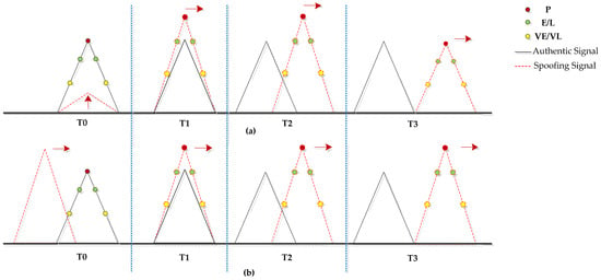
Figure 1.
Intermediate spoofing procedure: (a) Power-pulling strategy; (b) In-phase pulling strategy.
Both attack strategies are effective, primarily differing in the capture stage. The power-pulling strategy captures the receiver channel by precisely adjusting the false signal power, requiring the spoofing signal to have the same code delay and Doppler frequency as the authentic signal. In contrast, the other strategy synchronizes the spoofing signal by traversing the periodic code phase interval, without the need for exact knowledge of the received power and code phase of the authentic signal.
The in-phase pulling strategy is more feasible to implement with a larger effective area, as it only needs to set a certain spoofed velocity and power advantage at the beginning. On the other hand, the power-pulling strategy is less likely to be detected, as its spoofing signals are more approximated to the authentic signals. In this work, both the power-pulling strategy and the in-phase pulling strategy were utilized to verify spoofing detection methods.
2.2. Received Signal Model
The spoofing signal’s effect can be characterized by three parameters: the power advantage, code phase and carrier phase relative to the authentic signal. Assuming that the relative code phase is within ±2 chips, the received signal after frequency down-conversion in the front end can be modeled as:
where
and are the authentic signal and the spoofing signal, respectively;
is the authentic signal data bit stream;
is the spreading code of both signals;
is the received power of the authentic signal;
is the code phase of the authentic signal;
is the carrier phase of the authentic signal;
and are the intermediate frequency and Doppler frequency of the authentic signal, respectively;
, , and have the same meanings for the spoofing signal with time-varying properties;
is the additive white Gaussian noise with a one-sided power spectral density (PSD) of .
The locally generated replica signal can be modeled as:
where Tc is the chip duration, dTc is the code phase spacing between the local correlator and the prompt correlator and d is a unitless quantity. and are code phase and Doppler frequency estimates of the composite signal under an intermediate spoofing attack.
Assuming that the integration time is T, and the navigation data bit does not change in the integration interval, the kth correlation result can be expressed as:
where and are the parameter differences between the authentic signal and the local replica signal at the initial time of the kth integration. That is to say, and . and have the same meanings for the spoofing signal. is the average power of the fake signal over the kth integration interval. Moreover, the frequency estimation errors, and , can be converted into power loss by the correlation shape in the frequency domain.
is the complex Gaussian noise after integration, which can be modeled as:
is the thermal noise with a power of after integration. is the cross-correlation interference of the local signal with other PRN signals, because the code waveforms cannot be completely orthogonal. According to the large number theorem, can be approximated as white Gaussian noise with the power expression [29]:
Taking GPS L1 C/A signal as an example, s. If the integration time T equals the period of this spreading code, the power coefficient is . The received signal follows a nonstationary random distribution with a time-varying mean and variance. However, the cross-correlation can be ignored when the received power of fake signals approximates to that of true signals under an intermediate spoofing attack. In this case, the ambient noise floor far exceeds the cross-correlation level of the received signals.
Let parameter represent the power loss of frequency error, and Equation (3) can be simplified as:
where and . is the normalized autocorrelation function of an ideal BPSK modulation signal defined as:
Therefore, the post-correlation values in the in-phase (I) and quadrature (Q) channels can be written as:
where and are the in-phase and orthogonal components of Equation (6), respectively. and are the independent noise on these two branches.
3. Spoofing Detection
This section introduces the mechanism of spoofing detection and the setting of the corresponding threshold. The effect of correlator spacing is discussed. A detection strategy named as the M of N technique was adopted for the proposed test quantity in order to improve the effectiveness in practical applications.
3.1. Establishment of Test Quantity and Threshold
The synchronization of the carrier phase domain is difficult to realize for spoofing interference. Taking the GPS L1 C/A signal as an example, a cycle of the carrier phase corresponds to 19 cm, while a chip of the spreading code phase corresponds to about 300 m. Therefore, under an intermediate spoofing attack (H1), there will be abnormal energy in the Q channel correlators due to the carrier phase misalignment between the authentic signal and the fake signal. In the absence of the spoofing signal (H0), the correlator outputs of the Q channel primarily consist of noise components, given that the signal energy concentrates in the I channel. It is important to note that in practical applications, the spoofing detector needs to further determine whether the alarmed signal is a multipath signal or a spoofing signal. However, this specific aspect is beyond the scope of this paper and will not be addressed here.
We established a new spoofing detection quantity by monitoring the abnormal energy within the Q channel. The test quantity is defined as:
where and are the early and the late correlator outputs of the Q channel, respectively, is the calibration of the Q channel noise floor. The whole calculation process of is discussed in Section 3.3.
Taking the early correlator output as example and assuming that the receiver channel has already tracked the authentic signal and and are equal to zero, the output in the presence of the spoofing signal can be simplified as:
where is the Q channel additive Gaussian noise. The output follows the normal distribution . Therefore, the noise power-normalized output satisfies the distribution under H0 and H1 as:
where the noncentral parameter represents the ratio of power leakage of the spoofing signal in the Q channel to the noise, calculated as:
Assuming that the correlator spacing , so that and are mutually independent, the cumulative distribution function (cdf) of the test quantity satisfies:
The probability density function (pdf) of the test quantity is calculated under H0 and H1 as:
The probability of a false alarm under H0 and probability of detection can be calculated by:
where Th is the detection threshold.
The normalized outputs and both follow a central chi-squared distribution with 1 degree of freedom under H0. Hence, the threshold of the CFAR detector is determined by:
where is the right-tail probability for a chi-squared random variable with 1 degree of freedom, defined as [30]:
To validate the correctness of the probability analysis, we used the TEXBAT clean signal file “cleanStatic.bin”, which records the authentic signals received from the reference antenna. The test quantity was calculated during a tracking period of 60 s, and the statistical distribution is shown in Figure 2. It can be observed that the statistical result aligns well with the theoretical pdf curve of the detection statistic.
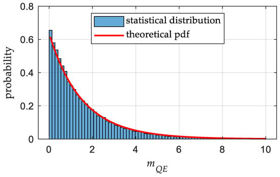
Figure 2.
Histogram and theoretical pdf curve of the normalized detection statistic.
3.2. Effect of Correlator Spacing
In the above statistical analysis, we assumed that the correlator spacing d was equal to 0.5, resulting in mutually independent early and late correlator outputs. However, when we have a narrower spacing, the early and late samples are correlated as [31]:
This correlation introduces complexities in analyzing the probabilities of related events and variables. From the perspective of limit theory, we can consider the effect of d on the test quantity, which can be regarded as the prompt correlator output:
where represents the prompt correlator output. The outputs , and follow the same normal distribution under H0.
Therefore, the pdf of the test quantity is calculated under H0 and H1 as:
where represents the ratio of power leakage of the spoofing signal in the Q channel to the noise.
According to Equation (17), the threshold of this detector is determined by:
In order to analyze the effect of correlator spacing on detection performance, the detection probabilities of these detectors from Equations (10) and (22) with the ratio are illustrated in Figure 3. With a given , the detection probability of these detectors can be obtained according to Equations (16), (18), (24) and (25). It is evident that the detector with d = 0 has a higher sensitivity to the ratio . From Figure 3, it is determined that the detection gain of the latter detector with d = 0 is 0.4 dB when , .
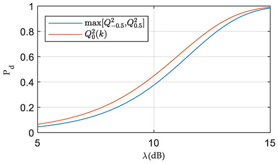
Figure 3.
Theoretical detection performance with the ratio of power leakage to the noise. ().
As the correlator spacing decreases, the correlation of the early and late samples is stronger. Compared to the detector with d = 0.5, which uses two independent variables with the OR fusion rule, the detector with a narrower spacing is less prone to false alarms under H0. Consequently, the CFAR threshold of the latter detector is lower with the same . As a result, the detection probability under H1 slightly increases as the correlator spacing decreases.
The selection of correlator spacing depends not only on the detection sensitivity, defined by the ratio of power leakage to the noise, but also on the detection effectiveness and receiver dynamics. Detection effectiveness refers to the ability of the spoofing detector to alarm when the spoofing signal has induced a significant error on the range measurement. With a narrower spacing, the spoofing detector has a lower detection effectiveness as it cannot alarm when the correlation curve of the spoofing signal is away from the tracking correlator. Moreover, the receiver dynamics may also cause slight leakage of the signal energy in the absence of spoofing attacks. According to Equations (9) and (10), a smaller correlator spacing d increases the likelihood of detection errors due to the carrier phase tracking error caused by dynamics. Therefore, we tended to choose a larger correlator spacing to avoid false alarms and missed alarms at the expense of detection sensitivity loss. In addition, the multicorrelator techniques may also improve the detection sensitivity and effectiveness [32]. For simplicity, we fixed the value of the correlator spacing d to 0.5 for all simulations and experiments.
3.3. Estimation of Noise Level
The noise floor, as indicated in Equations (4) and (5), is influenced by various factors, including thermal noise and cross-correlation between PRNs. It is necessary to obtain accurate calibration of the noise uncertainty. The noise channel technique was adopted to estimate the noise level. This technique involves correlating the received signal with a noise pseudocode, which belongs to the same family of codes used for GNSSs. The local reference signal of the noise channel is modeled as:
where is the noise pseudocode. The variance of correlation results represents the estimated noise level:
where is the kth correlation result, and are the code phase and Doppler frequency of the noise channel and M is the number of estimated points. The noise channel’s Doppler frequency matches the monitoring signal’s frequency.
In order to save the correlator resource, we utilized the parallel code phase correlation technique primarily employed for signal acquisition to calculate the correlation results. These results provide an estimation of the noise level:
where represents the sampling time and is the number of estimated points during the cyclic cross-correlation.
The noise floor was estimated and averaged first when the receiver channel was activated. It was assumed that the receiver initially tracks the authentic signal. Therefore, a reasonable estimation of the noise power under the null hypothesis can be obtained, which is applicable to the intermediate spoofing scenarios.
3.4. Detection Strategy
A detection strategy named as the M of N technique was adopted to optimize the detection performance, avoiding false alarms caused by noise fluctuations and platform dynamics, etc. This strategy is equivalent to a low-pass filtering process to the detection results at the expense of decision latency. The detection process is illustrated in Figure 4.
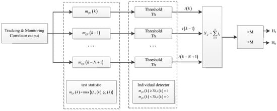
Figure 4.
Block diagram of spoofing detection.
The M of N detector is a sliding window of length N, based on current and preceding N−1 samples. If there is M or more samples that exceed the detection threshold, the detector outputs 1 or else 0. The overall probability of a false alarm under H0 is denoted as:
where is the cdf for a binomial random variable and is the false alarm probability in each trial.
Rearranging Equation (29) yields the single-trial probability in terms of the desired overall probability of false alarms, M and N [33]:
Then, we can obtain the detection threshold Th according to Equation (19).
The selection of N and M is critical to the detection performance. By a proper selection of M and N, this strategy can decrease the false alarm probability under H0 and increase the detection probability under H1, at the price of latency in the transition from the null to the alternate hypothesis and vice versa. Their appropriate values were determined based on the desired false alarm probability and spoofed velocity.
4. Simulation Results
This section numerically compares the detection performance of the proposed Q channel energy test quantity with the traditional SQM metrics. The conventional “Ratio” and “Delta” metrics were considered here as they are the base SQM metrics [32]. The correlation curve is usually distorted by the intermediate spoofing signal as shown in Figure 1. These SQM metrics, normalized by the I channel prompt value, are approximately normal distributed [22]. Their definition and theoretical statistics are shown in Table 1.

Table 1.
Definition of SQM metrics and theoretical statistics.
In the simulation test, we only considered the detection performance under a time-invariant parameter set, assuming that the tracking errors of the authentic signal were equal to 0. The influence of the Doppler difference can be mapped into the power advantage of the spoofing signal. Therefore, to facilitate the intuitive comparison of detection performance using different detection statistics, the influence of detection strategy on detection probability was disregarded by setting M = 1 and N = 1.
4.1. Evaluation Criterion
A good spoofing detection method is expected to be uniformly sensitive to a large range of relative code phases and carrier phases, considering that the relative code phase and carrier phase between the spoofing signal and its authentic counterpart vary during an intermediate spoofing attack. To evaluate the effectiveness of detection methods, we adopted the detectable area and overall detection ratio as evaluation indicators [22].
The detection area was composed of the relative code phase and carrier phase. The detectable area consisted of the detectable points whose detection probability (Pd) exceeded a preset threshold for a given . Additionally, the overall detection ratio was the ratio of the detectable area to the total detection area. A larger ratio indicates that the method is more robust to the variation of time-varying parameters.
4.2. Performance Evaluation
The Monte Carlo simulation process adopts a correlation domain simplified model introduced in reference [34]. The I and Q data are directly generated by this model avoiding massive correlation and spreading code generation. Two signal conditions with different CNRs of the authentic signal were considered to verify the effect of the noise level, and the integration time 10 ms. In the simulation process, a spoofing signal with 0.5 dB power advantage was added to the authentic signal whose tracking errors were equal to 0. The effect of the relative code phase and carrier phase for each detection method is shown in Figure 5 and Figure 6. The is fixed at 0.01, and the minimum acceptable equals 0.8.
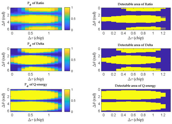
Figure 5.
Detection result and detectable area for each test quantity (CNR = 40 dB·Hz).
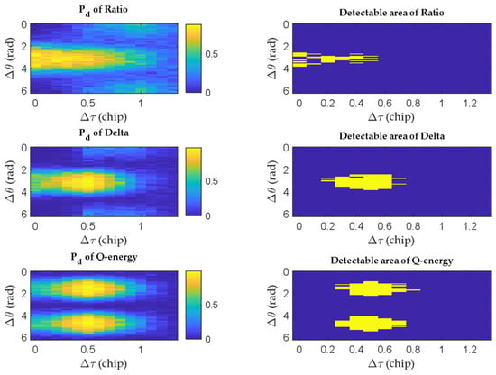
Figure 6.
Detection result and detectable area for each test quantity (CNR = 30 dB·Hz).
The left subfigures show the detection results of different methods, while those on the right show the detectable areas highlighted in yellow. It is obvious that the proposed test quantity has the largest detectable area under both signal conditions. The Q energy detector is much more robust to the relative code phase and carrier phase between the spoofing signal and the authentic counterpart compared to the traditional SQM metrics. The traditional SQM metrics have approximate detectable areas, with the Delta metric slightly outperforming the Ratio metric. However, the detection performance of the Q energy detector is poor when . That is to say, this detector is unable to detect the spoofing signal that is approximately in-phase or 180 degrees out-of-phase with the authentic signal under the same Doppler frequency. In these cases, both the fake signal and real signal concentrate in the I channel. But these cases are quite difficult for the spoofer to maintain, requiring calibration of various physical parameters. Even the Doppler frequency alignment is difficult to achieve.
Additionally, the Q energy detector can detect the spoofing signal when the traditional SQM detectors are ineffective for . The detectable area of the Q energy detector complements the shape of traditional SQM metrics because it utilizes different information for spoofing detection. This complementarity makes it possible to improve the spoofing detection performance by using different spoofing detectors jointly. However, the potential false alarm risk cannot be ignored.
From Figure 5 and Figure 6, we can see that the detectable area is sensitive to CNR. The decrease in CNR corresponds to either a drop in signal power due to the satellite elevation decreasing or an increase in the noise level caused by suppression jamming. The decrease in CNR would deteriorate the detection performance of all detectors. Table 2 shows the computed overall detection ratios for various signal conditions, with a spoofing power advantage of 0.5 dB and a correlator spacing of d = 0.5.

Table 2.
Overall detection ratios of different detectors under different signal conditions.
Table 2 demonstrates that the proposed detector significantly enhances detection performance compared to the traditional SQM metrics methods. When the CNR is less than 34 dB·Hz, the overall detection ratio of the traditional SQM metrics is less than 0.2. However, the Q energy detector exhibits a notable improvement in the overall detection ratio of at least 20% when the CNR exceeds 32 dB·Hz compared to the traditional SQM metrics. Furthermore, at a CNR of 38 dB·Hz, the detection ratio of the Q energy detector is comparable to that of the SQM metrics at a CNR of 44 dB·Hz.
5. Tests with TEXBAT Dataset
This section evaluates the detection performance of our proposed Q energy detector with a real spoofing dataset. This dataset, named the TEXBAT dataset, was provided by the University of TEXAS Radionavigation Laboratory [28]. This intermediate spoofing attack utilized the power-pulling strategy, as depicted in Figure 1a. The spoofing scenarios used in this paper are summarized in Table 3. In these spoofing attack scenarios, the GPS L1 C/A signals were analyzed. The spoofing signals were injected from 100 s. “Power Adv” indicates the power advantage of spoofing signals.

Table 3.
TEXBAT scenarios.
In the default mode of the carrier phase generation, which is the frequency locked mode, the spoofing signal maintains its carrier frequency identical to the authentic signal with a fixed carrier phase offset. This mode is designed to avoid large amplitude variations resulting from the varying relative carrier phase. On the other hand, in the frequency unlocked mode, a carrier frequency offset proportionate to the spoofed velocity is induced to ensure the consistency of the Doppler frequency between the carrier phase and code phase. However, the frequency unlocked mode may lead to the spoofing signal’s energy transition between the I and Q channels.
Considering the limitations of space, we used PRN 13 as an example for the static scenarios and PRN 22 for the dynamic scenarios. The dataset was processed by a modified version of the GPS software receiver discussed in reference [35]. The software receiver uses independent second-order carrier and code loops to track the received signal. The parameters of the tracking loop are as follows: the integration time 1 ms, the unitless correlator spacing 0.5, the DLL noise bandwidth 1 Hz and the PLL noise bandwidth 20 Hz, and the common loop gain and damping factor for both loops are 1 Hz and 0.707, respectively.
This section compares the proposed detector with the Delta metric, which outperforms the Ratio metric as shown in Table 2. Furthermore, we considered another SQM metric that relies on Q channel correlators and exhibits excellent detection performance in Scenarios 2 and 3 [27]. Its definition and theoretical statistics are shown in Table 4. This metric, normalized by the I channel prompt value, is distributed Rayleigh.

Table 4.
Definition of the Q channel SQM metrics and theoretical statistics.
At the beginning of each test, a 10-s calibration phase was conducted to calibrate the CNR and noise level under H0. This calibration enabled the calculation of detection thresholds for different test quantities.
5.1. Evaluation Criterion
This section evaluates the detection performance changes throughout the drag-off process by adopting the detection rate (DR) as the performance indicator. Unlike Section 4, which only considers the detection performance under a time-invariant parameter set, the detection probability cannot be used as an evaluation index. The parameters of the spoofing signal are time-varying in a drag-off process. The detection rate (DR) is similar to the overall detection ratio and is calculated by:
where represents the number of the test quantity that exceeds the threshold and L is the total number of the test quantity within the detection window.
It is worth noting that the M of N detection strategy would introduce a processing delay. When calculating the detection rate, the detection strategy was not used in order to accurately compare the detection performance changes of different detection methods. In this case, both of the M and N were set to 1 in this case.
The detection strategy was used to display the detection results, as it is crucial to minimize false alarms in practical application. The parameters for the detection strategy were determined as follows: the single-trial probability , and . That is to say, the M of N detector indicates a positive detection if there are more than 15 samples within 0.2 s exceeding the detection threshold. Therefore, the overall probability of false alarms satisfies according to Equation (29).
5.2. Static Power-Matched Scenarios
Taking Scenario 3 as an example, the spoofing signal’s power advantage is less than 2 dB. The corresponding detection results are shown in Figure 7. The M of N detection strategy was utilized to display the detection results. While some samples surpass the thresholds prior to the spoofing attack launched at 100 s, the spoofing detector will not generate a false alarm unless there are over 15 samples within 0.2 s that exceed the detection threshold.
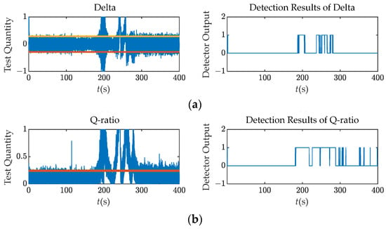

Figure 7.
Test quantities and detection results (M = 15, N = 200) over Scenario 3: (a) Delta; (b) Q ratio; (c) Q energy.
At around 200 s, the test quantities fluctuate dramatically due to the interaction between the spoofing and authentic signals. This interaction causes the energy leakage in the Q channel. The tracking loop finally locks onto the spoofing signal after the 300 s mark, resulting in a stable behavior of the test quantities. Moreover, at the time interval, the relative code phase is more than 1 chip, making it hard for these detectors to detect the spoofing attack as the correlation peaks are separate.
Figure 7 demonstrate that the Q channel detectors perform better than the Delta metric. The correlator outputs of Q-channel are only noise in the absence of the intermediate spoofing attack. When the relative code phase between the spoofing and authentic signals is within 2 chips, the abnormal energy in the Q channel due to the interaction is obvious. Therefore, it is much easier to monitor the abnormal energy within the Q channel than to monitor it within the I channel.
To provide a more comprehensive evaluation of their detection performance, Figure 8 presents the detection rates with a window length 10 and Receiver Operating Characteristic (ROC) curves for each detector. The ROC vertical axis uses the detection rate instead of the detection probability, and the detection window spans from 200 s to 300 s, corresponding to the drag-off stage one as discussed in Section 2.1. In Scenario 3, it is observed that the Q energy detector exhibits the highest sensitivity to the spoofing signal with a detection rate of 4.7% at 150 s. However, the overall detection performance of the Q energy detector is slightly inferior to that of the Q ratio detector.
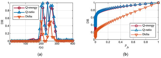
Figure 8.
Detection performance over Scenario 3: (a) Detection rates; (b) ROC curves.
5.3. Overpowered Scenarios
In Scenarios 1 and 4, the spoofer’s power advantage over the authentic signal ensemble is about 10 dB. The strong spoofing signal does not interact significantly with the authentic signal as the drag-off stage is smooth.
Taking the static case as an example, the detection results are shown in Figure 9. The Q energy detector outperforms the other two detectors for the entire period. This detector uses the calibration of the noise level, which is independent of the spoofing signal’s power, to normalize the test quantity. Meanwhile the SQM metrics use the I channel prompt correlator output to normalize. Because the spoofing signal is much stronger than the authentic one, the tacking loop fast approaches the spoofing signal, resulting in rapidly containing the energy of the spoofing signal. Consequently, the SQM metrics are relatively small. Therefore, in the high-power scenarios, the SQM metrics are less sensitive to the spoofing signal due the large normalization parameter.
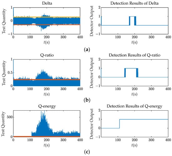
Figure 9.
Test quantities and detection results (M = 15, N = 200) over Scenario 1: (a) Delta; (b) Q ratio; (c) Q energy.
The detection rates and ROC curves for each detector over Scenario 1 are illustrated in Figure 10. The ROC detection interval spans from 150 s to 250 s, which corresponds to the drag-off stage one. It is observed that the Q energy detector exhibits the highest detection rate throughout the attacking process and is the earliest to detect the spoofing signal. Moreover, the detection rate of this detector remains above 40% after 250 s, indicating its ability to detect the spoofing signal even when the relative code phase exceeds 1 chip. In the overpowered scenarios, the cross-correlation interference caused by the spoofing signals cannot be overlooked, unlike the power-matched scenarios. The increased noise floor results in abnormal Q channel correlator output.
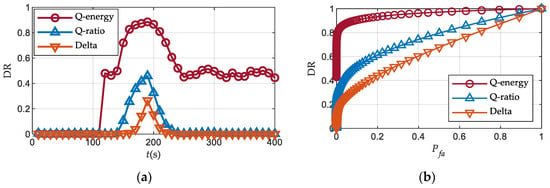
Figure 10.
Detection performance over Scenario 1: (a) Detection rates; (b) ROC curves.
Compared with Figure 8, it is evident that the Q energy detector performs better in the overpowered scenario with a detection rate exceeding 0.8 for . Conversely, the Q ratio detector performs even worse, mainly due to the differences in normalization parameters between these two methods. The performance of the Delta metric remains relatively unchanged.
5.4. Dynamic Scenarios
This subsection takes Scenario 5, the dynamic power-matched scenario, as an example. The detection results are shown in Figure 11. It is visible that compared with Figure 7, the test quantities are more unstable regardless of the spoofing signals.
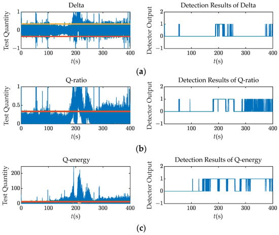
Figure 11.
Test quantities and detection results (M = 15, N = 200) over Scenario 5: (a) Delta; (b) Q ratio; (c) Q energy.
The platform dynamics may cause a slight leakage of the signal energy in the Q channel or deformation of the correlation peak due to the hysteresis characteristics of the tracking loop, leading to false alarms. Even the M of N detection strategy is considered to satisfy the overall probability of a false alarm , and the Delta and Q ratio detectors cannot avoid false alarms in dynamic scenarios. The M of N detectors using the SQM metrics output 1 at around 60 s when the spoofing signal has not been injected. In addition, it is important to note that the multipath signals, which result in similar distortions as the spoofing signals, can also increase the probability of spoofing false alarms. The multipath and spoofing classification techniques are beyond the scope of this paper and will not be addressed here.
Figure 12 demonstrates the detection rates and ROC curves with a detection window from 170 s to 270 s for each detector over Scenario 5. At 60 s, the Delta detector and the Q ratio detector exhibit detection rates of 2.6% and 4.0%, respectively, resulting in false alarms. Conversely, the Q energy detector achieves an almost negligible detection rate. Furthermore, the Q energy detector maintains its ability to detect the spoofing signal even after the 300 s mark when the tracking loop has essentially locked onto the spoofing signal, exhibiting a detection rate of approximately 20%. During this interval, the detector identifies the energy leakage of the spoofing signal due to dynamics. Specifically, the energy leakage of the authentic signal does not trigger alarms, whereas the slightly higher-power leakage of the spoofing signal does. The Q energy detector performs effectively in the dynamic scenario.
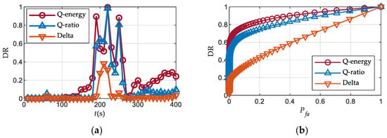
Figure 12.
Detection performance over Scenario 5: (a) Detection rates; (b) ROC curves.
In comparison to Figure 8, both the Q energy detector and the Delta detector exhibit minimal changes, while the performance of the Q ratio detector declines in the dynamic situation. This confirms the robustness of the Q energy detector.
Table 5 summarizes the detection rates for each detector under different scenarios with . The selection of the 100 s detection interval follows the same criteria as the above tests. It is evident that the Q energy detector exhibits superior performance in high-power scenarios and dynamic scenarios. The Q ratio detector also detects the abnormal energy in the Q channel and shows similar detection performance to the Q energy detector in static power-matched scenarios. However, the Q ratio detector utilizes the I channel prompt correlator output as the normalization parameter. This correlator output may rapidly increase, incorporating the energy of the spoofing signal when it is much stronger than the authentic signal. Consequently, the relatively small normalized test quantity causes a deterioration in the detection performance in the presence of an overpowered spoofing signal. In Table 5, its detection rate in the overpowered scenarios is at least 56% lower than that of the Q energy detector.

Table 5.
Detection rates over TEXBAT scenarios.
6. Field Data Analysis
This section presents a preliminary experiment conducted in the sky to test the applicability of the proposed method in real-world scenarios. This field experiment injects the spoofing signals in a different way compared to the TEXBAT dataset. Unlike the TEXBAT dataset, where the spoofing signals are injected into the receiver front end through a cable connection to the spoofer, this experiment involves the actual transmission of a spoofing signal at the BDS B1I frequency over the air. The B1I signals also adopt BPSK modulation as the GPS L1 C/A signals, except that the B1I signals are modulated with an additional 1 kbps secondary code, which has minimal influence on the spoofing detectors. Moreover, the intermediate spoofing attack utilizes the in-phase pulling strategy, as depicted in Figure 1b.
6.1. Experimental Setup
The test platform and scheme are shown in Figure 13 and Figure 14, respectively. The details of the equipment used in this experiment are shown in Table 6. In this experiment, IF samples were collected at a sampling rate of 25 MHz using a 2-bit quantizer. The spoofing signal was generated offline, requiring power calibration and parameter estimations beforehand. Therefore, we considered the PRN 3 signal transmitted by a geostationary satellite, as its change rate of the Doppler frequency is relatively small. In the initial 20 s of the experiment, no spoofing signal was transmitted to ensure that the receiver initially locks onto the authentic signal. It is worth noting that the focus of the preliminary experiment was on the drag-off process of the tracking loop. In order to clearly show that the loop was successfully pulled by the spoofing signal, we set all the data bits of the spoofing signal to 1. The data bits of the spoofing signal had little effect on the pull-off process. The spoofed velocity was 10 Hz in order to achieve the code-phase alignment in a relatively short time.
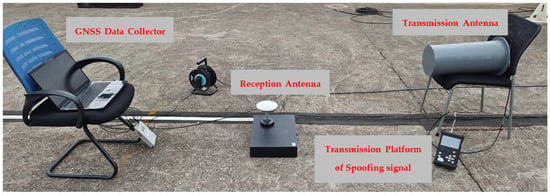
Figure 13.
Wireless test platform of the intermediate spoofing.
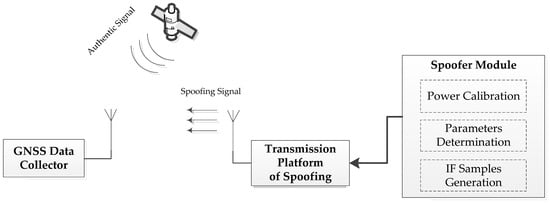
Figure 14.
Scheme of the spoofing attack.

Table 6.
Equipment list and model.
The software receiver was identical to that of Section 5, except that the local code was the B1I ranging code and the DLL’s noise bandwidth was increased from 1 Hz to 15 Hz. The PLL’ s noise bandwidth was still 20 Hz. The loop bandwidth was one of the key factors for the spoofing signals to pull off the tracking loop successfully. The spoofing signal can successfully drag off the tracking loop whose DLL bandwidth is comparable to the spoofed velocity. The acquisition and tracking results are shown in Figure 15 and Figure 16, respectively.

Figure 15.
Acquisition results: (a) t = 15 s; (b) t = 25 s.
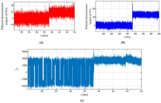
Figure 16.
Tracking results: (a) Filtered discriminator output of DLL; (b) Filtered discriminator output of PLL; (c) I channel prompt correlator output.
In the acquisition process, the local pseudocode was zero-padded with 1 ms to prevent data bit flip. The navigation message of the authentic signal was modulated with a 1 kbps secondary code. We only need to pay attention to the former code period in Figure 15. In this figure, two peaks can be observed in the correlation domain after the spoofing signal is transmitted. The new peak in Figure 15b, slightly higher than the original one, indicates that the spoofing signal is power-matched with the authentic signal.
Figure 16 shows that the spoofing signal successfully pulls off the tracking loop at around 38 s. The output of the loop filter corresponds to the time derivative of the local code/carrier phase. Figure 16a shows that the code frequency difference between the spoofing signal and the authentic signal is about 10 Hz, which is consistent with the preset spoofed velocity. Figure 16b indicates that the relative Doppler frequency is approximately 15 Hz, corresponding to the error of frequency calibration. The I channel prompt correlator output represents the data bit, and it is visible that the data bits of the tracked signal are all 1 after the 38 s mark. Additionally, the amplitude variation of the I channel correlator output suggests that the spoofing signal’s power approximates that of the authentic signal.
6.2. Performance Verification
Multiple data scenarios were collected by controlling the power attenuation of the spoofing signal, as shown in Table 7. The data collection process and the processing results of Scenario 1 are described in Section 6.1. The spoofing signal’s power advantage was calculated based on the estimated carrier-to-noise ratio before and after loop invasion.

Table 7.
Field data scenarios.
All these three scenarios in Table 4 belong to the Static Matched-Power Scenario with similar detection results. Taking Scenario 1 as an example, the effectiveness of the Q energy detector in the real world can be observed from Figure 17. This figure displays the outputs of the M of N detector and the proposed test quantities from 35 s to 45 s. Due to the high spoofed velocity of 10 Hz, the interval of correlator output fluctuation is short. Therefore, the N = 50 samples (or 0.05 s) and M = 5 samples were selected. The other configuration and process of this experiment are identical to those described in Section 5.
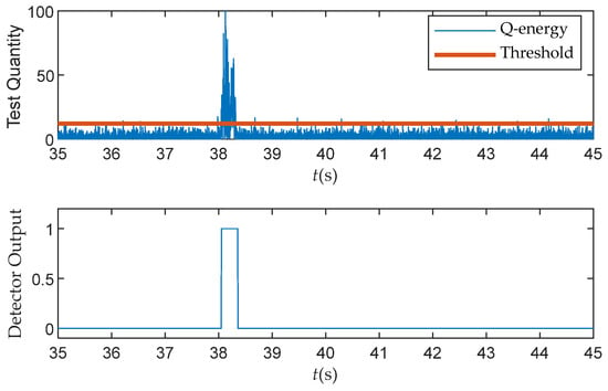
Figure 17.
Test quantity and detection result (M = 5, N = 50) over the real dataset.
In order to further evaluate the detection performance of different detectors, Figure 18 shows the detection rates with a window length of L = 100 ms in Scenario 1. The implementation process and details main consistent with those presented in Section 5. As can be seen from Figure 18, it is evident that in the static power-matched detection scenario, the detectors based on the Q channel energy outperform the traditional SQM metrics.
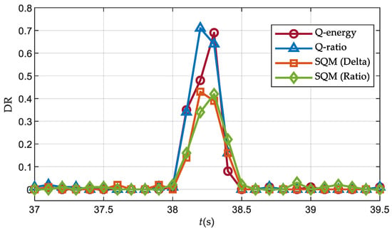
Figure 18.
Detection rates over Scenario 1 (J/S = 0.5 dB).
It is worth noting that the spoofing signal was not synchronized with the real signal until 38 s, and the loop remained unaffected during this period. Therefore, for the intermediate spoofing detection method, the detection rate can be considered as the false alarm probability at this time. Therefore, the Q ratio and Delta detectors exhibit false alarms at 37.1 s and 37.6 s, respectively, with an approximate false alarm rate of 2%.
Figure 19 and Figure 20 display the detection rates in Scenario 2 and Scenario 3, respectively, revealing the impact of the power advantage of the spoofing signal. The results indicate that a higher power of the spoofing signal leads to superior detection performance with the Q energy detector, in comparison to the Q ratio detector.
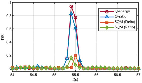
Figure 19.
Detection rates over Scenario 2 (J/S = 2.0 dB).
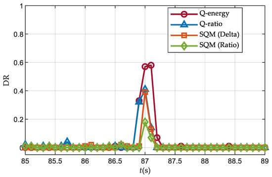
Figure 20.
Detection rates over Scenario 3 (J/S = 3.5 dB).
It should be noted that the detection rate of the Q energy detector decreases when the power advantage of the spoofing signal is 3.5 dB. This is because with much higher spoofing signal power, the carrier loop quickly converges to the deception signal, resulting in less energy of the deception signal on the orthogonal branch. Unlike the overpowered scenario in Section 5.3, the field experiment conducted in this section only transmitted the PRN 3 satellite signal, so the noise introduced by the cross-correlation interference of the deception signal was not significant.
7. Conclusions
This article proposes a spoofing detector based on the quadrature channel energy, which uses the estimation of the noise level as the normalization parameter. The simulation results numerically validate its robustness to the variation of the relative code phase and carrier phase. The Q energy detector improves the overall detection ratio by at least 20% when the CNR exceeds 32 dB·Hz, as compared to the traditional SQM metrics. Furthermore, this detector outperforms the traditional I channel SQM metric in all scenarios of the TEXBAT dataset. It exhibits superior performance in high-power scenarios and robustness to receiver dynamics, successfully avoiding false alarms caused by the dynamics. Additionally, field tests are conducted to verify the applicability of the proposed method in the real world. The results show that increasing the power of the spoofing signal improves the relative detection performance of the Q energy detector compared to other SQM detectors.
This detector can be an effective defense technique against spoofing attacks without modifying the baseband correlators. It provides an enhanced detection at the onset of the intermediate spoofing attack.
Further developments could focus on discriminating the spoofing signal from the multipath signal. The multipath signals, which result in similar distortions as the spoofing signals, can also increase the probability of spoofing false alarms. Additionally, further research is needed to effectively execute intermediate spoofing attacks in the air. This requires real-time and accurate estimation of the signal parameters.
Author Contributions
Conceptualization, J.W. (Jiaqi Wang) and X.T.; methodology, J.W. (Jiaqi Wang); software, J.W. (Jiaqi Wang) and C.M.; validation, J.W. (Jiaqi Wang) and J.W. (Jian Wu); formal analysis, J.W. (Jiaqi Wang); investigation, all; resources, X.T. and G.S.; data curation, J.W. (Jiaqi Wang) and P.M.; writing—original draft preparation, J.W. (Jiaqi Wang), X.T. and P.M.; writing—review and editing, C.M., G.S. and J.W. (Jian Wu); visualization, J.W. (Jiaqi Wang); supervision, X.T., C.M. and J.W. (Jian Wu); project administration, X.T., P.M. and C.M.; funding acquisition, X.T. and G.S. All authors have read and agreed to the published version of the manuscript.
Funding
This research was funded by the National Natural Science Foundation of China (Grant No. U20A0193) and the Science and Technology Innovation Program of Hunan Province (Grant No. 2021RC3073).
Data Availability Statement
The Texas Spoofing Test Battery (TEXBAT) dataset was provided by the University of TEXAS Radionavigation Laboratory and is available from https://rnl-data.ae.utexas.edu/datastore/texbat/ (accessed on 20 April 2022). In addition, the processed field test dataset can be requested up on the author.
Acknowledgments
The authors would like to thank the editors and reviewers for their efforts to help the publication of this paper.
Conflicts of Interest
The authors declare no conflict of interest.
References
- Jafarnia-Jahromi, A.; Broumandan, A.; Nielsen, J.; Lachapelle, G. GPS vulnerability to spoofing threats and a review of antispoofing techniques. Int. J. Navig. Obs. 2012, 2012, 127072. [Google Scholar] [CrossRef]
- Shepard, D.P.; Humphreys, T.E. Characterization of receiver response to spoofing attacks. In Proceedings of the 24th International Technical Meeting of the Satellite Division of The Institute of Navigation (ION GNSS 2011), Portland, OR, USA, 20–23 September 2011; pp. 2608–2618. [Google Scholar]
- Bhatti, J.; Humphreys, T.E. Hostile control of ships via false GPS signals: Demonstration and detection. NAVIGATION J. Inst. Navig. 2017, 64, 51–66. [Google Scholar] [CrossRef]
- Ma, C.; Yang, J.; Chen, J.; Qu, Z.; Zhou, C. Effects of a navigation spoofing signal on a receiver loop and a UAV spoofing approach. GPS Solut. 2020, 24, 76. [Google Scholar] [CrossRef]
- Humphreys, T.E.; Ledvina, B.M.; Psiaki, M.L.; O’Hanlon, B.W.; Kintner, P.M. Assessing the spoofing threat: Development of a portable GPS civilian spoofer. In Proceedings of the 21st International Technical Meeting of the Satellite Division of the Institute of Navigation, Savannah, GA, USA, 16–19 September 2008; pp. 2314–2325. [Google Scholar]
- Gao, Y.; Li, G. A new asynchronous traction signal spoofing algorithm for PLL-assisted DLL receiver. GPS Solut. 2023, 27, 141. [Google Scholar] [CrossRef]
- Wang, Y.; Sun, F.P.; Hao, J.M.; Zhang, L.D.; Wang, X. Reduction research on performance index system of satellite navigation system spoofing. GPS Solut. 2022, 26, 43. [Google Scholar] [CrossRef]
- Psiaki, M.L.; Humphreys, T.E. GNSS spoofing and detection. Proc. IEEE 2016, 104, 1258–1270. [Google Scholar] [CrossRef]
- Daneshmand, S.; Jafarnia-Jahromi, A.; Broumandon, A.; Lachapelle, G. A low-complexity GPS anti-spoofing method using a multi-antenna array. In Proceedings of the 25th International Technical Meeting of the Satellite Division of the Institute of Navigation (ION GNSS 2012), Nashville, TN, USA, 17–21 September 2012; pp. 1233–1243. [Google Scholar]
- Psiaki, M.L.; O’Hanlon, B.W.; Bhatti, J.A.; Shepard, D.P.; Humphreys, T.E. Civilian GPS spoofing detection based on dual-receiver correlation of military signals. In Proceedings of the 24th International Technical Meeting of the Satellite Division of the Institute of Navigation (ION GNSS 2011), Portland, OR, USA, 20–23 September 2011; pp. 2619–2645. [Google Scholar]
- Günther, C. A survey of spoofing and counter-measures. NAVIGATION J. Inst. Navig. 2014, 61, 159–177. [Google Scholar] [CrossRef]
- Huang, L.; Lu, Z.; Ren, C.; Liu, Z.; Xiao, Z.; Song, J.; Li, B. Research on detection technology of spoofing under the mixed narrowband and spoofing interference. Remote Sens. 2022, 14, 2506. [Google Scholar] [CrossRef]
- Hu, Y.; Bian, S.; Cao, K.; Ji, B. GNSS spoofing detection based on new signal quality assessment model. GPS Solut. 2018, 22, 28. [Google Scholar] [CrossRef]
- Wesson, K.D.; Gross, J.N.; Humphreys, T.E.; Evans, B.L. GNSS signal authentication via power and distortion monitoring. IEEE Trans. Aerosp. Electron. Syst. 2017, 54, 739–754. [Google Scholar] [CrossRef]
- Jafarnia Jahromi, A.; Broumandan, A.; Nielsen, J.; Lachapelle, G. GPS spoofer countermeasure effectiveness based on signal strength, noise power, and C/N0 measurements. Int. J. Satell. Commun. Netw. 2012, 30, 181–191. [Google Scholar] [CrossRef]
- Jafarnia-Jahromi, A.; Lin, T.; Broumandan, A.; Nielsen, J.; Lachapelle, G. Detection and mitigation of spoofing attacks on a vector based tracking GPS receiver. In Proceedings of the 2012 International Technical Meeting of the Institute of Navigation, Newport Beach, CA, USA, 30–31 January 2012; pp. 790–800. [Google Scholar]
- Troglia Gamba, M.; Truong, M.D.; Motella, B.; Falletti, E.; Ta, T.H. Hypothesis testing methods to detect spoofing attacks: A test against the TEXBAT datasets. GPS Solut. 2017, 21, 577–589. [Google Scholar] [CrossRef]
- Liu, K.; Wu, W.; Wu, Z.; He, L.; Tang, K. Spoofing detection algorithm based on pseudorange differences. Sensors 2018, 18, 3197. [Google Scholar] [CrossRef] [PubMed]
- Gao, W.; Li, H.; Lu, M. Multi-channel joint signal quality monitor method for detecting GNSS time synchronization attacks. In Proceedings of the 34th International Technical Meeting of the Satellite Division of the Institute of Navigation (ION GNSS+), St. Louis, MO, USA, 20–24 September 2021; pp. 4274–4287. [Google Scholar]
- Yang, Y.; Li, H.; Lu, M. Performance assessment of signal quality monitoring based GNSS spoofing detection techniques. In Proceedings of the China Satellite Navigation Conference (CSNC) 2015 Proceedings, Xi’an, China, 13–15 May 2015; pp. 783–793. [Google Scholar]
- Jahromi, A.J.; Broumandan, A.; Daneshmand, S.; Lachapelle, G.; Ioannides, R.T. Galileo signal authenticity verification using signal quality monitoring methods. In Proceedings of the 2016 International Conference on Localization and GNSS (ICL-GNSS), Barcelona, Spain, 28–30 June 2016. [Google Scholar]
- Sun, C.; Cheong, J.W.; Dempster, A.G.; Zhao, H.; Feng, W. GNSS spoofing detection by means of signal quality monitoring (SQM) metric combinations. IEEE Access 2018, 6, 66428–66441. [Google Scholar] [CrossRef]
- Benachenhou, K.; Bencheikh, M.L. Detection of global positioning system spoofing using fusion of signal quality monitoring metrics. Comput. Electr. Eng. 2021, 92, 107159. [Google Scholar] [CrossRef]
- Sun, C.; Cheong, J.W.; Dempster, A.G.; Demicheli, L.; Cetin, E.; Zhao, H.; Feng, W. Moving variance-based signal quality monitoring method for spoofing detection. GPS Solut. 2018, 22, 83. [Google Scholar] [CrossRef]
- Pirsiavash, A.; Broumandan, A.; Lachapelle, G. Two-dimensional signal quality monitoring for spoofing detection. In Proceedings of the ESA/ESTEC NAVITEC 2016 Conference, Noordwijk, The Netherlands, 14–16 December 2016. [Google Scholar]
- Pirsiavash, A.; Broumandan, A.; Lachapelle, G.; O’Keefe, K. Detection and classification of GNSS structural interference based on monitoring the quality of signals at the tracking level. In Proceedings of the 6th ESA International colloquium of Scientific and Fundamental Aspects of Galileo, Valencia, Spain, 25–27 October 2017. [Google Scholar]
- Sun, C.; Cheong, J.W.; Dempster, A.G.; Zhao, H.; Bai, L.; Feng, W. Robust spoofing detection for GNSS instrumentation using Q-channel signal quality monitoring metric. IEEE Trans. Instrum. Meas. 2021, 70, 8504115. [Google Scholar] [CrossRef]
- Humphreys, T.E.; Bhatti, J.A.; Shepard, D.; Wesson, K. The Texas spoofing test battery: Toward a standard for evaluating GPS signal authentication techniques. In Proceedings of the 25th International Technical Meeting of the Satellite Division of the Institute of Navigation (ION GNSS 2012), Nashville, TN, USA, 17–21 September 2012. [Google Scholar]
- Holmes, J.K. Spread Spectrum Systems for GNSS and Wireless Communications; Artech House Inc.: Norwood, MA, USA, 2007; pp. 179–181. [Google Scholar]
- Kay, S.M. Fundamentals of Statistical Signal Processing: Detection Theory; Prentice Hall PTR: Hoboken, NJ, USA, 1993; pp. 21–26. [Google Scholar]
- Van Dierendonck, A.J.; Fenton, P.; Ford, T. Theory and performance of narrow correlator spacing in a GPS receiver. Navigation 1992, 39, 265–283. [Google Scholar] [CrossRef]
- Pirsiavash, A. Receiver-Level Signal and Measurement Quality Monitoring for Reliable GNSS-Based Navigation. Ph.D. Thesis, University of Calgary, Calgary, AB, Canada, 2019. [Google Scholar]
- Ward, P.W. GPS receiver search techniques. In Proceedings of the Position, Location and Navigation Symposium-PLANS’96, Atlanta, GA, USA, 22–25 April 1996; pp. 604–611. [Google Scholar]
- Langer, M.; Kiesel, S.; Kief, K.F.; Trommer, G.F. Simulation and efficient implementation of a multipath estimating delay locked loop using FIMLA algorithm. In Proceedings of the 24th International Technical Meeting of the Satellite Division of the Institute of Navigation (ION GNSS 2011), Portland, OR, USA, 20–23 September 2011; pp. 1152–1161. [Google Scholar]
- Borre, K.; Akos, D.M.; Bertelsen, N.; Rinder, P.; Jensen, S.H. A Software-Defined GPS and Galileo Receiver: A Single-Frequency Approach; Springer Science & Business Media: Berlin, Germany, 2007; pp. 81–84. [Google Scholar]
Disclaimer/Publisher’s Note: The statements, opinions and data contained in all publications are solely those of the individual author(s) and contributor(s) and not of MDPI and/or the editor(s). MDPI and/or the editor(s) disclaim responsibility for any injury to people or property resulting from any ideas, methods, instructions or products referred to in the content. |
© 2023 by the authors. Licensee MDPI, Basel, Switzerland. This article is an open access article distributed under the terms and conditions of the Creative Commons Attribution (CC BY) license (https://creativecommons.org/licenses/by/4.0/).