Abstract
The Land Surface GNSS Reflection Simulator (LAGRS)-Soil model represents a significant advancement in soil moisture detection with the aid of Global Navigation Satellite System (GNSS) Occultation Sounder-Reflectometry (GNOS-R) technology, which is one payload of the Fengyun-3E (FY-3E) satellite that was launched on 5 July 2021. To fully exploit the properties of noncoherent scattering, the LAGRS-Soil model has the capability to calculate DDM information for different observational geometries, which relies on the random surface scattering models employed in LAGRS-Soil. This will provide a comprehensive understanding of soil moisture dynamics across diverse terrains and environments. One of the most notable features of LAGRS-Soil is its ability to obtain DDMs for full polarizations, which enhances soil moisture retrievals compared to current methods that only utilize the commonly used LR polarization (left-hand circular polarization received and right-hand circular polarization transmitted). Meanwhile, the model can also capture frozen soil DDMs which holds immense potential for near-surface Freezing/Thawing (F/T) detection, opening up new research and application opportunities in cold climate regions. LAGRS-Soil is built on microwave scattering models, making it a robust and efficient theoretical model for the FY-3E GNOS-R payload. This model can support ongoing soil moisture retrieval efforts by combining physical models with investigations of diffuse scattering and polarization capabilities for soil moisture detection.
1. Introduction
Over the past three decades, Global Navigation Satellite System-Reflectometry (GNSS-R) has evolved into a promising remote sensing technique, benefiting from the ready availability of transmitters [1]. A pioneering spaceborne GNSS-R experiment was conducted using the United Kingdom-Disaster Monitoring Constellation (UK-DMC), launched in September 2003, which was successful in recording reflected signals not only from the ocean surface but also from the land surface [2]. Subsequently, the TechDemoSat-1 GNSS-R satellite was launched on 8 July 2014, and its GNSS-R receiver performs real-time navigation and generates delay Doppler maps (DDMs) for Earth-reflected Global Positioning System (GPS) L1 C/A ranging signals [3]. NASA launched the Cyclone Global Navigation Satellite System (CYGNSS) in 2016, which comprises eight microsatellites. The scientific applications of this constellation have expanded beyond the detection of ocean parameters to include monitoring and retrieval of soil moisture, vegetation biomass, flood inundation, wetlands, and near-surface soil freeze/thaw state [4,5,6,7,8,9,10,11,12,13,14,15,16,17,18,19,20,21]. It is worth noting that the two GNSS-R CubeSats recently launched by Spire also have the capability to provide soil moisture products [22]. On 5 July 2021, China launched its Fengyun-3E (FY-3E) meteorological satellite. One of the payloads onboard this satellite is the GNSS Occultation Sounder (GNOS)-II, which combines GNSS-R and GNSS radio occultation techniques [23,24].
As spaceborne GNSS-R missions continue to increase, previous research has demonstrated the feasibility and significant potential for soil moisture retrieval using this approach [25]. Therefore, one of the primary scientific objectives of the Fengyun-3E (FY-3E) GNOS-R is to detect soil moisture. However, due to the relatively recent development of this technique for soil moisture detection using spaceborne GNSS-R, some uncertainties remain, such as the definition and utility of coherent and noncoherent signals, and the dependence on external auxiliary data during the inversion process, including Soil Moisture Active Passive (SMAP) data [25]. Despite the uncertainties, further research focused on the mechanism level could help address most of the current issues in soil moisture retrieval using spaceborne GNSS-R [26].
This paper presents a full-polarization GNSS-R model, specifically the Land Surface GNSS Reflection Simulator (LAGRS)-Soil model, which is suitable for use with the FY-3E GNOS-R payload [27]. The direct signals from GNSS constellations and the reflected signals by the Earth’s surface operate similarly to a bistatic radar. Coherent signals are commonly used for the present soil moisture retrieval. However, noncoherent scattering signals derived from observational geometries other than the specular point should also be captured and fully utilized. To account for this, the LAGRS-Soil model includes calculations of both coherent and noncoherent scattering.
One potential application of GNOS-R is for near-surface soil F/T detection, and therefore the innovative capability of the LAGRS-Soil model to develop frozen soil DDMs will provide theoretical support in the near future for GNOS-R mapping of F/T in global cold regions.
The full polarization calculation is another important novelty of the LAGRS-Soil model. This allows for a more comprehensive analysis of the signals received from the Earth’s surface, taking into account not only LR polarization but also RR (right-hand circular polarization received and left-hand circular polarization transmitted) polarization and other linear-circular combined polarization components [28]. The LAGRS-Soil model takes into account the unique polarization characteristics of the signals transmitted by GNSS constellations, which are right-hand circulation polarization (RHCP). This is different from the traditional linear polarization used in monostatic radars and radiometers, and the polarization can flip following reflection from the Earth’s surface. The polarization characteristics of electromagnetic waves are influenced by various factors such as the dielectric constant, physical properties, geometric shapes, and orientation. Therefore, research on GNSS-R polarization is important for the extraction of target parameters and the improvement of soil moisture detection and retrieval processes.
In Section 2, we provide an overview of the FY-3E GNSS-R payload, i.e., GNOS-R. A flowchart and a description of the unique features of LAGRS-Soil are presented in Section 3. The results and validation of simulations using FY-3E GNOS-R data are presented in Section 4. Finally, the derived conclusions are stated in Section 5.
2. Overview of FY-3E GNOS-R Payload
The FY-3E satellite was successfully launched on 5 July 2021 and is the fifth of China’s second-generation polar-orbiting meteorological satellites. It includes the GNOS-II payload, which has the capability for multiple GNSS calculations and can produce not only GPS-Reflectometry data but also China’s Beidou-Reflectometry data. The GNOS-II system consists of eight reflected channels, including four GPS channels and four Beidou Navigation Satellite System channels. Following the completion of the test phase, Galileo reflection products will also be provided. The inclination of FY-3E is 98.8°, which provides a global coverage capability (±85° latitude) compared to the pan-tropical coverage of CYGNSS. The intervals in delay and Doppler dimensions of TechDemoSat-1 and CYGNSS’s Level 1 data are uniform. This means that data from around the specular point are often used for soil moisture retrieval, while other information derived from the glistening zone is neglected. However, this phenomenon will be resolved by the design of the nonuniform DDM of GNOS-R that is intended to obtain full utilization of the GNSS-R correlator resource. There are 12 hot points designed to receive raw sampling data, the locations of which are presented in Figure 1.
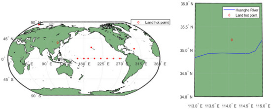
Figure 1.
Locations of hot points (red dots) for receiving raw sampling data. The land surface hot point is shown by the diamond.
3. Simulator Structure and Theoretical Formulas
The KA-GO (Kirchhoff Approach-Geometrical Optics)-based Z-V scattering model is widely used in the GNSS-R field. This model establishes a physical connection between observation geometric parameters, environmental parameters, and received measurement outputs. The essence of the model is the bistatic radar integral form, and the Kirchhoff approximation under the double-scale model is used to calculate the bistatic scattering characteristics on the ocean surface [29]. According to Masters’ Ph.D. thesis, forward scattering on land is very close to that on the ocean surface, and they believe that theoretical simulations on the ocean surface are also applicable to land surfaces (Z-V-M) [30]. The main difference between the ocean surface and land surface is the difference in dielectric constants. For land surfaces, surface roughness and vegetation cover are the main factors affecting scattering characteristics. This model was extended to soil moisture applications [30], where the ground reflectance was calculated using the GO model. Both models used LR polarization.
Under the sponsorship of the LEIMON project, Pierdicca et al. developed the SAVERS (Soil and Vegetation Reflection Simulator) model, which built a basic framework of the Z-V model frame [29]. The signal-dependent output energy of DDMs is a function of time delay and Doppler frequency shift. The model is divided into two parts [31]: an observation geometry calculation module and a ground reflectance calculation module. The coherent and noncoherent scattering coefficients of bistatic scattering were modified, and the coherent and noncoherent scattering properties of bare soil were calculated using Fung and Eom’s coherent scattering coefficients and advanced integral equation (AIEM) model, respectively [31]. Vegetation scattering was calculated using Tor Vergata’s model [31]. After determining the transmitter and receiver positions and velocities, they were put into the geometric module of the model to obtain the image reflection point, as well as the antenna pattern and Doppler range. After coupling with the scattering coefficient module that obtained the reflectance surface scattering characteristics, the final DDM was obtained. The polarization used in the model includes RR and LR polarization.
The SCoBi-Veg (Signals of opportunity Coherent Bistatic scattering model for Vegetated terrains) is a bistatic model designed for SoOP-R vegetation remote sensing applications. The framework of this model is Monte Carlo, which can simulate the polarized reflectance characteristics of vegetation canopies on flat surfaces [32]. The model assumes that the signal incident source is a navigation satellite or digital communication satellite signal, and the frequency coverage includes P-band and S-band. The model is fully polarized.
The LAGRS-Veg model is an on-board DDM simulation and analysis system for vegetation [33]. This model can calculate the impact of tall forests and low shrubs on scattering characteristics, and then analyze their impact on DDM waveforms. The model is mainly based on the first-order radiation transfer equation model, modified to obtain a full-polarization scattering model. It establishes a physical mechanism model between the navigation satellite signal and vegetation and then obtains the corresponding scattering mechanism model.
The LAGRS-Soil model is a GNOS-R simulation and analysis system for soil that includes three novelties. Firstly, it can calculate DDM waveforms that include specular scattering and diffuse scattering characteristics. Secondly, it has a fully polarized calculation function, which is an extension module designed for future space-borne payload designs. The DDM module for surface freeze–thaw characteristics is the third new feature designed for soil moisture inversion and monitoring of near-surface freeze–thaw conditions in cold regions. Specifically, the comparison between the above models and this model is shown in Table 1.

Table 1.
Comparison between space-borne DDM simulators.
The LAGRS-Soil model developed for FY-3E GNOS-R has two major improvements compared to previous models. Firstly, it takes into account both the coherent scattering properties of bare soil and the diffuse scattering properties, which are determined based on accurate observational geometry. This improvement is made by improving the coherent scattering model and random surface scattering models. Secondly, the LAGRS-Soil model is capable of performing calculations of full polarization, which will benefit soil moisture retrieval and future improvements to the GNOS-R payload. A polarization synthesis technique is used for these calculations. The details of the employed models and the corresponding formulas are explained in this section.
3.1. General Structure of the Model
The LAGRS simulator was developed based on the ocean surface GPS scattering model, which is an integral form of the bistatic radar equation. This model describes the behavior of electromagnetic waves as they propagate from the transmitter to the receiver and takes into account factors such as the Earth’s curvature, altitude, and dielectric properties [29]. LAGRS has two main modules: one is the geometry module obtained from the velocity and the position of the transmitter and receiver, and the other is the bistatic scattering cross-section module. Most forms of the Z-V (Zenith-Vertical) model used for bare soil applications use a modification of Fresnel reflectivity to obtain the surface coherent scattering properties. However, few models consider polarization calculations. The LAGRS model, which was developed for FY-3E GNOS-R, can perform both full polarization calculations and noncoherent scattering calculations using random surface scattering models. A flowchart of the simulator is presented in Figure 2.
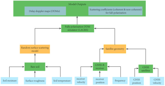
Figure 2.
LAGRS flowchart.
By inputting the basic parameters of bare soil (i.e., soil moisture, temperature, and roughness) into bare soil scattering models, the dielectric constants of the bare soil can be achieved. They are inserted into the corresponding scattering models, and the related scattering coefficients can be obtained. This information should be combined with the details of the satellite geometry and input into the FY-3E GNOS-R DDM module. The geometry information is obtained from the position and the velocity of the GNSS transmitters and the corresponding GNOS-R receiver. The core of LAGRS for the generation of the DDMs is the Z-V model [29]. The output of LAGRS is the DDMs and the intermediate values of the scattering coefficients can also be determined. The final power of LAGRS has two components: coherent and noncoherent components [31]:
The coherent part can be calculated as follows:
While the noncoherent part can be expressed by the following formula:
where R is the distance (subscript t and t1 mean the distance from the reflection point to the transmitter, and r and r1 indicate the distance from the reflection point to the receiver), as the velocity and position of the transmitter and receiver are fixed, the corresponding distances for R can be clearly calculated; the transmitted power of the GNSS satellite is PT; GT and GR represent the antenna gain of the transmitter and the receiver, respectively; is the area of the facet; and represent the coherent reflection coefficient and the noncoherent scattering coefficient, respectively; p and q indicate the received or transmitted polarization, respectively; and and represent the core part of LAGRS development.
3.2. Observational Geometry and Coordinate Systems
The observational geometry coordinate system used by LAGRS is presented in Figure 3 [34]. In this system, hr and ht represent the height of the GNSS satellite receiver (R) and transmitter (T), respectively, above the Earth’s surface, and Re is the local Earth radius (using the circular Earth model, Re is 6,378,137 m). Parameters G and L are the distances from transmitter T and receiving platform R to the center of the Earth, respectively, α is the angle between the geocentric connection of the GNSS satellite and the specular reflection point O, is the angle between the GNSS satellite receiving platform and the geocentric connection, ε is the angle between the receiver, the specular reflection point O, and the line connecting to the center of the Earth, and θ is the elevation angle of the scattered signal relative to the local section, i.e., the satellite altitude angle. Parameters d and D represent the distances from the receiver and the transmitter to the specular reflection point, respectively. The relationship between these variables is shown in the following formulas:
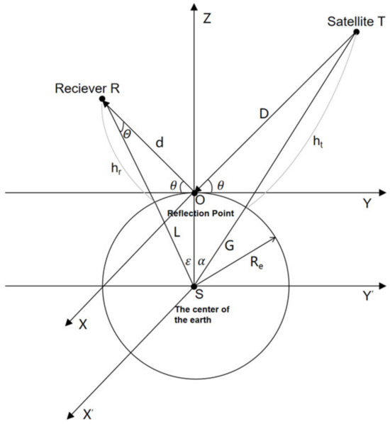
Figure 3.
Observational geometry of LAGRS.
The positions of R and T in the local coordinate system are (0, ,) and (0,,), respectively, while their positions in the geocentric coordinate system are (0, , + ) and (0,, + ), respectively.
3.3. Bare Soil Scattering Models
The most important part of the developed model is the soil scattering computation module. In GNSS-R, it is commonly assumed that the scattering of bare soil is from the specular direction; therefore, the coherent scattering model developed by Fung and Eom [35] is used in the LAGRS-Soil model. As surface roughness increases, diffuse scattering becomes important. Therefore, the diffuse scattering obtained from the random rough surface scattering model is employed to calculate the scattering properties in this direction [36].
3.3.1. Concepts of the Random Rough Surface Scattering Models
As for the integral area, the observation geometry (incidence angles and scattering zenith and azimuth angles) for each grid varies with the GNSS transmitter and corresponding receiver movement. For the specular point, we use the Fung and Eom equation to calculate the specular scattering coefficient, while random rough surface scattering models are employed for other diffuse scattering directions. The roughness of a random surface can be characterized by its root-mean-square (rms) surface height and the surface correlation function . The vertical characteristic of the surface can be represented by , while the horizontal characteristic can be expressed through the surface correlation length , if its form is specified. The commonly used models to obtain the noncoherent contribution from a random rough surface include the Geometrical Optics (GO) model, Physical Optics (PO) model, Small Perturbation Model (SPM), Integral Equation Model (IEM), and Advanced Integral Equation Model (AIEM). Table 2 presents the valid and recommended conditions for different LAGRS-Soil models.

Table 2.
Valid and recommended conditions for different LAGRS-Soil models, where is the surface root mean square slope, is the surface correlation length, s is the surface rms height, and is the GNSS wavelength [26].
The first three models are suitable for different surface roughness. The Geometrical Optics (GO) model is best suited for very rough surfaces, the Physical Optics (PO) model is suitable for intermediate surface roughness, and the Small Perturbation Model (SPM) should be adopted for short correlation lengths. It is important to note that the roughness scale of a natural surface varies continuously; therefore, the more recently developed Integral Equation Model (IEM) and Advanced Integral Equation Model (AIEM) are best suited for the calculation, although the latter provides greater accuracy. In our simulator, all of the above-mentioned models are used to perform the noncoherent scattering calculation.
3.3.2. Frozen Soil Models
The freeze–thaw cycle is an important process in soil moisture in cold regions. It refers to the repeated freezing and thawing of the active layer soil in permafrost and seasonal frozen soil areas due to cyclic temperature changes. The freeze–thaw process affects the water and heat characteristics of soil, during which liquid water and vapor in soil migrate, and the freezing and melting of water will inevitably exchange heat, while the temperature of the soil will also change accordingly. Therefore, the LAGRS-Soil model should also include the ability to model frozen soil DDMs. When the temperature of soil falls below zero degrees Celsius, its dielectric constant is influenced by various factors, including soil properties (such as texture, organic matter content, and salinity), water content, temperature, and frequency. Among these factors, temperature variations play a significant role in the transformation of soil freeze–thaw (F/T) processes. To calculate frozen soil DDMs, the Zhang-Zhao dielectric constant model is included in the LAGRS-Soil model to combine with the random roughness surface model [37,38].
While and are the real part and imaginary part of the dielectric constant. The subscripts m, s, fw, and i represent the moist soil, mineral particles, frozen water (containing free and bound water), and ice, respectively. The subscripts u and i represent volume proportions of unfrozen water and ice, respectively. α is the shape factor. β′ and β″ are empirical parameters related to soil texture to express the effect of bound water. The relationship between the real part and imaginary part of the dielectric constant with soil temperature is shown in Figure 4. We can observe that there is a noticeable shift as the soil transitions from a frozen state to a thawing state.
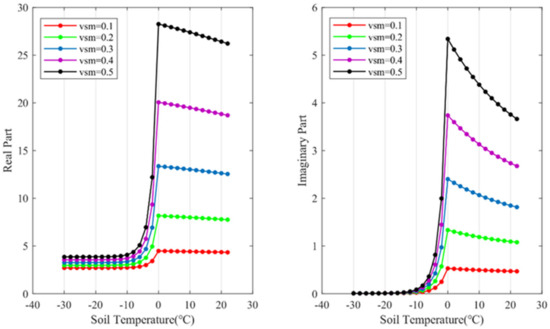
Figure 4.
The dielectric constant of the real part (shown in the left figure) and imaginary part (shown in the right figure) versus soil temperature at different soil moisture contents for GPS L1 frequency band.
This enables the LAGRS-Soil model to have the ability to calculate frozen soil DDMs and extend its application to soil moisture retrieval in cold regions and near-surface soil freeze/thaw process detection for future polarization-enabled GNSS-R payloads.
3.3.3. Methodology of Polarization Calculations
The conventional random surface scattering models are primarily designed for linear polarization calculations. These models are not directly applicable to GNSS-R data due to the complex nature of the signal in GNSS-R systems, and therefore modifications may be necessary when applying them to GNSS-R remote sensing.
When considering scattering from an object, there are two main conventions for defining the polarization of the GNSS-R wave: Forward Scatter Alignment (FSA) and Back Scatter Alignment (BSA). The differences between the BSA and FSA conventions are presented in [39,40]. In the field of radar polarimetry, the BSA convention has become the standard. However, since many scattering formulations employ the FSA convention, it is important to be able to convert the wave synthesis results between the BSA and FSA conventions.
The polarization state of a wave can be expressed in terms of modified Stokes vectors, which are related to the standard Stokes vectors by a simple transformation matrix. In developing a random scattering model suitable for full-polarization GNSS-R study, we adopted a 4 × 4 real matrix relating the incident and scattered Stokes vectors. This enables the calculation of the bistatic scattering cross section for any combination of transmitted and received polarizations using wave synthesis techniques, as shown in Equation (14) [39,40].
where and are the modified stokes vectors of the received and transmitted polarization, respectively, which are functions of the orientation and ellipticity angles.
For the coherent scattering part, in accordance with the above-mentioned models and the wave synthesis technique, we adopted the specular reflectivity:
where Re and Im represent the real part and the imaginary part of the corresponding equations, respectively, R is the Fresnel reflectivity, subscripts v and h are the vertical and horizontal polarizations, respectively, and * denotes the conjunctive values. The random surface scattering models, according to the complex formulas, are employed to derive the corresponding Mueller matrix; thus, we can obtain the scattering properties at various polarizations, where the general form of the Mueller matrix M is as follows:
While S is the average scattering amplitude coefficient at pq polarization, where pq can be either vertical (v) or horizontal (h) polarization. Re and Im are used to obtain the real and imaginary parts of the dielectric constant, respectively, while * is the conjugate.
4. Model Simulations and Validations
The capability of the model and the validity of the corresponding simulations are considered in this section. It should be noted that the extension with full-polarization capability is also illustrated. One important point that should be noted is that the other components used for FY-3E GNOS-R, such as the observational geometry and the noise portion, are all set to ideal conditions. In this way, the effects of the scene generation components can be elucidated.
4.1. Capability of Noncoherent Scattering Waveform
Using the scattering models presented in Section 2, it is possible to obtain the surface scattering properties at various observational geometries, including not only the scattering coming from the specular point but also the noncoherent scattering from the glistening zone. Figure 5 illustrates the scattering at various polarizations and observational geometries. With our developed models, the energy derived under different observational geometries can be determined. This means that with the information from different scattering azimuth angles, we can obtain the observational geometry. The incident angle is typically between 8° and 9°.
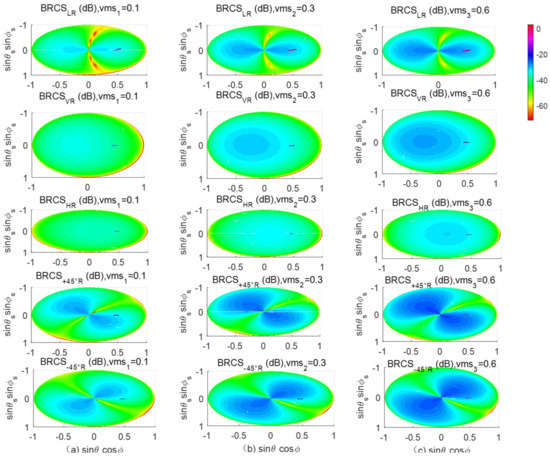
Figure 5.
Scattering coefficients at various polarizations for all possible observational geometries [36,39] the soil moisture content for a, b, c are 0.1, 0.3 and 0.6, respectively.
The distributions of the scattering zenith angle and the azimuth angles are shown in Figure 6.

Figure 6.
Scattering observational geometries used for the simulations. (a) is for the incidence angle, (b) is the scattering zenith angle and (c) is the scattering azimuth angle.
The settings of coherent and noncoherent scattering will affect the final DDMs. It was mentioned in the previous section that different scattering models are employed for coherent and noncoherent scattering; however, defining coherent and noncoherent scattering is very important. Strictly, scattering only in the direction of θi = θs or φi = φs can be defined as in the specular direction, where θ is the scattering zenith angle and φ is the scattering azimuth angle, and subscripts i and s are the incidence angle and scattering angle, respectively. However, if we ignore the effect of the scattering azimuth angle, and believe that the angles are in the form of θi = θs, then the scattering from the specular cone is coherent scattering. Thus, we can adopt the scattering coefficients of Fung and Eom to obtain the coherent scattering.
The details of the settings of the observational geometry are shown in Table 3, and the tolerances of different scattering azimuth angles are also provided for the final simulations. The settings of the observational geometry and the tolerance of the scattering azimuth angles will affect the final DDMs.

Table 3.
Settings of the observational geometry.
The simulations corresponding to the setting listed in Table 3 are shown in Figure 7. It can be seen that if we want to derive the noncoherent scattering and obtain full utilization of the scattering information at the noncoherent part, then definite settings for the observational geometry will benefit the classification of the noncoherent DDMs.
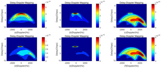
Figure 7.
DDMs illustrating noncoherent components. The observational geometry settings are shown in Table 3, while the setting for (a) is case 1, (b) is case 2, (c) is case 3, (d) is case 4, (e) is case 5, and (f) is case 6.
4.2. Capability of Full Polarizations
Because we modified the surface scattering model to obtain the scattering at various polarization combinations, LAGRS-Soil can calculate the polarization DDMs. With LAGRS-Soil, we can derive the full-polarization spaceborne outputs. This means that if the transmitted signals are RHCP, then the reflected signals of RHCP, LHCP, H, V, +45°, and −45° polarizations can all be calculated using our developed models, where the aforementioned polarizations can be denoted RR, LR, HR, VR, +45°R, and −45°R, respectively. Of course, the calculations for linear polarization can also be achieved, i.e., HH, VV, HV, and VH. This is the unique feature of LAGRS-Soil.
Although the FY-3E GNOS-R payload was not originally designed for polarization GNSS-R, we have extended LAGRS-Soil to provide polarization calculation capability. This allows us to investigate polarization GNSS-R and potentially improve our understanding of soil moisture retrieval. A companion paper to this one discusses this topic in detail [37]. Figure 8 provides an initial illustration of the DDMs at LR, VR, and HR polarizations.
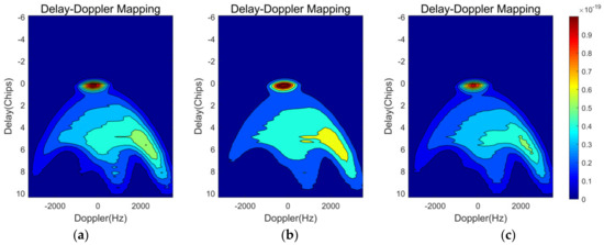
Figure 8.
DDMs at LR polarization (a), VR polarization (b), and HR polarization (c).
Different polarizations can affect the DDM waveforms not only in the specular direction but also in the diffuse direction. By combining the polarization information, we can potentially retrieve soil moisture with greater accuracy and effectively remove the effects of surface roughness and vegetation coverage.
4.3. Responses of Different Soil Parameters
The physical characteristics of bare soil, such as moisture content, texture, temperature, salinity, and surface roughness, can all affect the dielectric constants, which are the most important influencing factors of surface reflectivity and scattering coefficients. With our developed LAGRS-Soil model, we can investigate these effects to better understand how they impact remote sensing applications. In this section, we consider the effects of soil moisture and temperature because we hope to use spaceborne GNSS-R data to retrieve soil moisture content and the soil freeze/thaw state. Figure 9 illustrates the effect of soil moisture on the final DDMs as the soil moisture content is changed from 0.1 to 0.6.
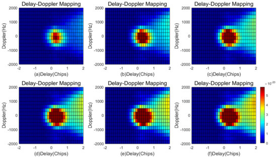
Figure 9.
Effect of soil moisture on the final DDMs: (a–f) volumetric soil moisture content from 0.1 to 0.6 in intervals of 0.1.
It can be observed that the soil moisture content not only affects the scattering at the center of the coherent direction but also affects the edges and pattern of the scattering in the diffuse direction. This phenomenon becomes more pronounced as the delay (Chips) increases, as shown in Figure 10. The simulated correlation power versus delay (Chips) for different soil moisture contents clearly illustrates this effect. By understanding how soil moisture affects the scattering behavior of GNSS-R signals, we can potentially improve our ability to accurately retrieve soil moisture information from spaceborne GNSS-R data.
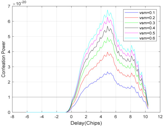
Figure 10.
Simulated correlation power versus delay (Chips) for different soil moisture contents.
It should also be noted that LAGRS-Soil can calculate frozen soil DDMs, which means it could be used to retrieve the soil freeze/thaw state. This is potentially one of the most important applications of the FY-3E GNSS-R payload. Figure 10 and Figure 11 show obvious differences in the DDMs obtained for frozen and thawed soil. For soil moisture content of 0.3, the soil temperature was set to −1 °C for the frozen soil and 1 °C for the thawed soil; all other input parameters were set to the same values as in the previous section. Therefore, the change in soil temperature from below freezing to above freezing was responsible for the change in the DDMs. The complex dielectric constant at −1 °C is 8.64 + 1i, while that at 1 °C is 21.05 + 3.54i. The substantial difference in the dielectric constant affects the final DDMs.
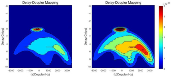
Figure 11.
Simulated correlation power versus delay (Chips) for (a) frozen and (b) thawed soil.
The DDM patterns at the center point of the delay and Doppler frequency, shown in Figure 11, are evidently different and show that frozen soil has higher values. The DDM patterns at delays (Chips) larger than two are also illustrated, from which apparent changes can be identified.
4.4. Data Validation
Data validation is crucial for ensuring the accuracy of a developed model. We selected areas of the Sahara desert for data validation. We excluded areas with topography and large water bodies to ensure that our model could accurately represent the behavior of bare soil in these conditions.
To validate our model, we tested it on three points in the Sahara desert where GNOS-R data are available. These locations are detailed in Table 4. By using these specific locations, we can ensure that our model’s performance is not affected by variations in terrain or water availability that may exist elsewhere in the desert.

Table 4.
Details of locations of GNOS-R data in the Sahara Desert.
SMAP (Soil Moisture Active Passive) data were used as ancillary information for validating our model. Specifically, we obtained the roughness coefficient from SMAP L1 data for three of the tested sites, which had a roughness coefficient of 0.15. Additionally, we analyzed the clay fraction and soil moisture content for these sites, as shown in Figure 12. From the figure, it is clear that the soil was almost dry at the tested sites. To calculate the dielectric constant for the desert, we used the Zhang-Zhao semi-empirical model. The model takes into account the bulk density of the soil, which was set to 1.6 g/cm3. Using this model, we were able to obtain an accurate estimate of the dielectric constant for the Sahara desert, which will be useful for further analysis and model development. From the DDMs shown in Figure 13, we use the following equation to obtain the surface reflectivity (SR):
where is the SR, and are the distances from the specular point to the receiver and to the transmitter, respectively, is the peak DDM power, refers to noise, and is the DDM bistatic radar cross section factor.
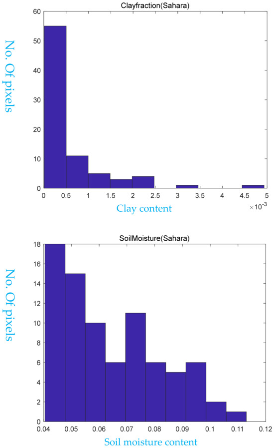
Figure 12.
Clay fraction and soil moisture information of the Sahara Desert from 15–18 July 2021.

Figure 13.
FY-3E GNOS-R DDMs.
Comparison of the SR derived from the DDMs in Figure 13 with that of the model outputs revealed reasonable consistency with a correlation coefficient as high as 0.90.
5. Conclusions
This paper presents a novel full-polarization GNSS-Reflectometry model for bare soil applications in the FY-3E GNOS-R payload, i.e., the LAGRS-Soil model. The model is specifically designed to simulate and analyze spaceborne DDMs in the presence of bare soil. Three advancements and novelties of the models are noncoherent scattering for different observation geometries, the ability to calculate the frozen soil DDMs, and the calculations of full polarization. LAGRS-Soil’s unique feature is its use of microwave scattering models to provide a physical connection between the received signals and the GNSS transmitted source. This allows for a more accurate interpretation of spaceborne DDMs and enhanced retrieval of soil moisture information. The physical characteristics of bare soil, including soil moisture, temperature, and surface roughness, directly impact the derived spaceborne DDMs. The LAGRS-Soil model takes these factors into account when simulating and analyzing DDMs in the FY-3E GNOS-R payload. The LAGRS-Soil model includes a polarization extension module that encompasses not only LR polarization but also RR polarization and other linear-circular polarization combinations. This design feature is expected to support future polarization upgrades for GNSS-R and related GNOS-R applications. The LAGRS-Soil model includes a surface temperature module that accounts for the impact of surface temperature on DDM waveforms. This feature, along with the polarization extension module, is expected to provide a theoretical framework for the future use of GNOS-R for monitoring surface freeze–thaw conditions and enhancing our understanding of soil moisture dynamics in various environments. To verify and validate the LAGRS-Soil model, three cases of typical desert land surface were simulated using FY-3E GNOS-R data and ancillary data calculated from SMAP. The results showed good agreement between the simulated and actual DDMs, indicating that the model can effectively capture the physical characteristics of bare soil and provide accurate predictions of DDMs. In future research, semi-physical parameterized models will be developed using the LAGRS-Soil model for soil moisture retrievals. These models will build upon the physical connections established by the LAGRS-Soil model and provide a more comprehensive toolset for analyzing soil moisture dynamics in various environments.
Author Contributions
Methodology, X.W. and F.W.; Software, X.O.; Validation, J.X. and Z.Y. All authors have read and agreed to the published version of the manuscript.
Funding
This research was funded by the National Natural Science Foundation of China (No. 42061057).
Data Availability Statement
Data are available from the references as presented in the paper.
Conflicts of Interest
The authors declare no conflict of interest.
References
- Zavorotny, V.U.; Gleason, S.; Cardellach, E.; Camps, A. Tutorial on Remote Sensing Using GNSS Bistatic Radar of Opportunity. IEEE Geosci. Remote Sens. Mag. 2014, 2, 8–45. [Google Scholar] [CrossRef]
- Gleason, S.; Adjrad, M.; Unwin, M. Sensing ocean, ice and land reflected signals from space: Results from the UK-DMC GPS reflectometry experiment. In Proceedings of the 18th International Technical Meeting of the Satellite Division of The Institute of Navigation, Long Beach, CA, USA, 13–16 September 2005; pp. 1679–1685. [Google Scholar]
- Camps, A.; Vall·llossera, M.; Park, H.; Portal, G.; Rossato, L. Sensitivity of TDS-1 GNSS-R Reflectivity to Soil Moisture: Global and Regional Differences and Impact of Different Spatial Scales. Remote Sens. 2018, 10, 1856. [Google Scholar] [CrossRef]
- Li, W.; Cardellach, E.; Fabra, F.; Ribo, S.; Rius, A. Assessment of Spaceborne GNSS-R Ocean Altimetry Performance Using CYGNSS Mission Raw Data. IEEE Trans. Geosci. Remote Sens. 2020, 58, 238–250. [Google Scholar] [CrossRef]
- Clarizia, M.P.; Ruf, C.S. Wind Speed Retrieval Algorithm for the Cyclone Global Navigation Satellite System (CYGNSS) Mission. IEEE Trans. Geosci. Remote Sens. 2016, 54, 4419–4432. [Google Scholar] [CrossRef]
- Yi, Y.; Johnson, J.T.; Wang, X. Diurnal Variations in Ocean Wind Speeds Measured by CYGNSS and Other Satellites. IEEE Trans. Geosci. Remote Sens. 2022, 19, 1–5. [Google Scholar] [CrossRef]
- Asharaf, S.; Waliser, D.E.; Posselt, D.J.; Ruf, C.S.; Zhang, C.; Putra, A.W. CYGNSS Ocean Surface Wind Validation in the Tropics. J. Atmos. Oceanic Technol. 2021, 38, 711–724. [Google Scholar] [CrossRef]
- Yueh, S.H.; Shah, R.; Chaubell, M.J.; Hayashi, A.; Xu, X.; Colliander, A. A Semiempirical Modeling of Soil Moisture, Vegetation, and Surface Roughness Impact on CYGNSS Reflectometry Data. IEEE Trans. Geosci. Remote Sens. 2022, 60, 1–17. [Google Scholar] [CrossRef]
- Loria, E.; O’Brien, A.; Zavorotny, V.; Downs, B.; Zuffada, C. Analysis of Scattering Characteristics from Inland Bodies of Water Observed by CYGNSS. Remote Sens. Environ. 2020, 245, 111825. [Google Scholar] [CrossRef]
- Ghasemigoudarzi, P.; Huang, W.; De Silva, O.; Yan, Q.; Power, D. A machine learning method for inland water detection using CYGNSS data. IEEE Geosci. Remote Sens. Lett. 2022, 19, 1–5. [Google Scholar] [CrossRef]
- Morris, M.; Chew, C.; Reager, J.T.; Shaw, R.; Zuffada, C. A novel approach to monitoring wetland dynamics using CYGNSS: Everglades case study. Remote Sens. Environ. 2019, 233, 111417. [Google Scholar] [CrossRef]
- Kim, H.; Lakshmi, V. Use of Cyclone Global Navigation Satellite System (CyGNSS) Observations for Estimation of Soil Moisture. Geophys. Res. Lett. 2018, 45, 8272–8282. [Google Scholar] [CrossRef]
- Clarizia, M.P.; Pierdicca, N.; Costantini, F.; Floury, N. Analysis of CYGNSS data for soil moisture retrieval. IEEE J. Sel. Top. Appl. Earth Obs. Remote Sens. 2019, 12, 2227–2235. [Google Scholar] [CrossRef]
- Carreno-Luengo, H.; Luzi, G.; Crosetto, M. Above-Ground Biomass Retrieval over Tropical Forests: A Novel GNSS-R Approach with CyGNSS. Remote Sens. 2020, 12, 1368. [Google Scholar] [CrossRef]
- Chew, C.; Reader, J.T.; Small, E. CYGNSS data map flood inundation during the 2017 Atlantic hurricane season. Sci. Rep. 2018, 8, 9336. [Google Scholar] [CrossRef]
- Chew, C.; Small, E. Estimating inundation extent using CYGNSS data: A conceptual modeling study. Remote Sens. Environ. 2020, 246, 111869. [Google Scholar] [CrossRef]
- Zhang, S.; Ma, Z.; Li, Z.; Zhang, P.; Liu, Q.; Nan, Y.; Zhang, J.; Hu, S.; Feng, Y.; Zhao, H. Using CYGNSS Data to Map Flood Inundation during the 2021 Extreme Precipitation in Henan Province, China. Remote Sens. 2021, 13, 5181. [Google Scholar] [CrossRef]
- Zeiger, P.; Frappart, F.; Darrozes, J.; Prigent, C.; Jiménez, C. Analysis of CYGNSS Coherent Reflectivity over Land for the Characterization of Pan-tropical Inundation Dynamics. Remote Sens. Environ. 2022, 282, 113278. [Google Scholar] [CrossRef]
- Wu, X.; Dong, Z.; Jin, S.; He, Y.; Song, Y.; Ma, W.; Yang, L. First Measurement of Soil Freeze/Thaw Cycles in the Tibetan Plateau Using CYGNSS GNSS-R Data. Remote Sens. 2020, 12, 2361. [Google Scholar] [CrossRef]
- Carreno-Luengo, H.; Ruf, C.S. Retrieving freeze/thaw surface state from CYGNSS measurements. IEEE Trans. Geosci. Remote Sens. 2021, 60, 1–13. [Google Scholar] [CrossRef]
- Carreno-Luengo, H.; Ruf, C.S. Mapping Freezing and Thawing Surface State Periods With the CYGNSS Based F/T Seasonal Threshold Algorithm. IEEE J. Sel. Top. Appl. Earth Obs. Remote Sens. 2022, 15, 9943–9952. [Google Scholar] [CrossRef]
- Freeman, V.; Esterhuizen, S.; Jales, P.; Masters, D. Spire’s new GNSS-R soil moisture products collected from small and innovative Earth observing satellites. In Proceedings of the SPIE 11528, Remote Sensing for Agriculture, Ecosystems, and Hydrology XXII, San Francisco, CA, USA, 20 September 2020; p. 115280F. [Google Scholar] [CrossRef]
- Yang, G.; Bai, W.; Wang, J.; Hu, X.; Zhang, P.; Sun, Y.; Xu, N.; Zhai, X.; Xiao, X.; Xia, J.; et al. FY3E GNOS II GNSS Reflectometry: Mission Review and First Results. Remote Sens. 2022, 14, 988. [Google Scholar] [CrossRef]
- Liu, X.; Bai, W.; Xia, J.; Huang, F.; Yin, C.; Sun, Y.; Du, Q.; Meng, X.; Liu, C.; Hu, P.; et al. FA-RDN: A Hybrid Neural Network on GNSS-R Sea Surface Wind Speed Retrieval. Remote Sens. 2021, 13, 4820. [Google Scholar] [CrossRef]
- Lei, F.; Senyurek, V.; Kurum, M.; Gurbuz, A.; Boyd, D.; Moorhead, R. Quasi-Global GNSS-R Soil Moisture Retrievals at High Spatio-Temporal Resolution from Cygnss and Smap Data. In Proceedings of the 2021 IEEE International Geoscience and Remote Sensing Symposium IGARSS, Brussels, Belgium, 11–16 July 2021; pp. 6303–6306. [Google Scholar] [CrossRef]
- Fung, A.K. Microwave Scattering and Emission Models and Their Applications; Artech House: Norwood, MA, USA, 2009; pp. 1–450. [Google Scholar]
- Wu, X.; Xia, J. A Land Surface GNSS Reflection Simulator (LAGRS) FORFY-3E GNSS-R Payload: Part I. Bare Soil Simulator. In Proceedings of the 2021 IEEE Specialist Meeting on Reflectometry Using GNSS and Other Signals of Opportunity (GNSS + R), Beijing, China, 14–17 September 2021; pp. 90–92. [Google Scholar] [CrossRef]
- Wu, X.; Shi, J. Polarization GNSS-Reflectometry: Potential and Possibility. In Proceedings of the 2021 IEEE Specialist Meeting on Reflectometry Using GNSS and Other Signals of Opportunity (GNSS + R), Beijing, China, 14–17 September 2021; pp. 29–31. [Google Scholar] [CrossRef]
- Zavorotny, V.U.; Voronovich, A.G. Scattering of GPS signals from the ocean with wind remote sensing application. IEEE Trans. Geosci. Remote Sens. 2000, 38, 951–964. [Google Scholar] [CrossRef]
- Masters, D.S. Surface Remote Sensing Applications of GNSS Bistatic Radar: Soil Moisture and Aircraft Altimetry; University of Colorado: Denver, CO, USA, 2004. [Google Scholar]
- Pierdicca, N.; Guerriero, L.; Giusto, R.; Brogioni, M.; Egido, A. SAVERS: A Simulator of GNSS Reflections From Bare and Vegetated Soils. IEEE Trans. Geosci. Remote Sens. 2014, 52, 6542–6554. [Google Scholar] [CrossRef]
- Kurum, M.; Deshpande, M.; Joseph, A.T.; O’Neill, P.E.; Lang, R.H.; Eroglu, O. SCoBi-Veg: A Generalized Bistatic Scattering Model of Reflectometry From Vegetation for Signals of Opportunity Applications. IEEE Trans. Geosci. Remote Sens. 2019, 57, 1049–1068. [Google Scholar] [CrossRef]
- Wu, X.; Wang, F. LAGRS-Veg: A spaceborne vegetation simulator for full polarization GNSS-reflectometry. GPS Solut. 2023, 27, 107. [Google Scholar] [CrossRef]
- Yang, D.K.; Zhang, Q. GNSS Reflected Signal Processing: Fundamentals and Applications; Publishing House of Electronics Industry: Bejing, China, 2012. [Google Scholar]
- Fung, A.; Eom, H. Coherent scattering of a spherical wave from an irregular surface. IEEE Trans. Antennas Propag. 1983, 31, 68–72. [Google Scholar] [CrossRef]
- Chen, K.S.; Wu, T.D.; Tsang, L.; Li, Q.; Shi, J.C.; Fung, A.K. Emission of rough surfaces calculated by the integral equation method with comparison to three-dimensional moment method simulations. IEEE Trans. Geosci. Remote Sens. 2003, 41, 90–101. [Google Scholar] [CrossRef]
- Zhang, L.; Zhao, T.; Jiang, L.; Zhao, S. Estimate of phase transition water content in freeze–thaw process using microwave radiometer. IEEE Trans. Geosci. Remote Sens. 2010, 48, 4248–4255. [Google Scholar] [CrossRef]
- Wu, S.; Zhao, T.; Pan, J.; Xue, H.; Zhao, L.; Shi, J. Improvement in modeling soil dielectric properties during freeze-thaw transitions. IEEE Geosci. Remote Sens. Lett. 2022, 19, 1–5. [Google Scholar] [CrossRef]
- Wu, X.; Jin, S. Models and Theoretical Analysis of SoOp Circular Polarization Bistatic Scattering for Random Rough Surface. Remote Sens. 2020, 12, 1506. [Google Scholar] [CrossRef]
- Ulaby, F.T.; Sarabandi, K.; Mcdonald, K.; Whitt, M. Michigan microwave canopy scattering model. Int. J. Remote Sens. 1990, 11, 1223–1253. [Google Scholar] [CrossRef]
Disclaimer/Publisher’s Note: The statements, opinions and data contained in all publications are solely those of the individual author(s) and contributor(s) and not of MDPI and/or the editor(s). MDPI and/or the editor(s) disclaim responsibility for any injury to people or property resulting from any ideas, methods, instructions or products referred to in the content. |
© 2023 by the authors. Licensee MDPI, Basel, Switzerland. This article is an open access article distributed under the terms and conditions of the Creative Commons Attribution (CC BY) license (https://creativecommons.org/licenses/by/4.0/).