Abstract
The problem of accurately measuring the motion parameters of low radar cross-section (RCS) maneuvering targets has long been a hurdle in the radar technology landscape. Small targets, due to their elusive characteristics, are particularly difficult to detect with conventional radar systems. In this paper, we investigate the capabilities of dechirp-receiving stepped-frequency radar, a modern system using a linear frequency modulation signal for downconversion. This permits the radar to function at reduced sampling rates while maintaining the transmission of large-bandwidth signals and achieving synthetic imaging. Our primary contribution is introducing the stepped dechirp generalized Radon–Fourier transform (stepped DGRFT) algorithm. This novel approach allows the radar system to perform coherent accumulation, enhancing the accuracy of motion parameter estimates for low-RCS maneuvering targets. Results from our simulations and measured data analysis validate the effectiveness of our proposed algorithm, demonstrating its superiority over other methods.
1. Introduction
Low radar cross-section (RCS) targets, which have been continuously emerging over the past few years, pose significant threats and challenges to radar detection [1,2,3]. To achieve high-resolution imaging and accurate motion parameter estimation of low-RCS maneuvering targets, radar systems must employ wideband or ultrawideband signals. This approach enables the acquisition of more target information, thereby enhancing target classification and identification [4,5].
Ideally, radar can directly transmit and receive large-bandwidth linear frequency modulation (LFM) signals and use dechirping processing to obtain a high-resolution range profile (HRRP) [6]. However, current limitations in radio frequency (RF) unit design and sampling rate make it difficult to directly dechirp ultrawideband signals. Furthermore, the use of large-bandwidth signals can easily produce issues such as amplitude and phase distortion. Direct dechirping processing of such signals is not conducive to refined processing, such as amplitude, phase and velocity compensation, which affects the imaging quality of the target. By contrast, stepped-frequency signals can be processed coherently in multiframes to realize larger-bandwidth synthetic imaging by using a small subpulse bandwidth [7,8], and multiple subpulses can be processed separately to realize amplitude, phase, and velocity compensation to enhance the imaging quality [9]. Consequently, subpulse wideband dechirping can be integrated with a stepped frequency [10] to realize dechirping of stepped-frequency large-bandwidth signals, that is, the transmission of wideband chirp signals in subpulses, dechirping of the echoes, and performing frequency hopping between pulses. Targets can thus be imaged using large-bandwidth signals by integrating coherent methods, such as spectrum splicing, time-domain splicing, and amplitude, and phase and velocity compensation.
A target with a low RCS has an extremely low signal-to-noise ratio (SNR); hence, the radar system needs to extend the coherent processing interval (CPI) to obtain a sufficient coherent accumulation gain to stably detect maneuvering weak targets [11,12]. However, extending the coherent accumulation time for maneuvering targets often leads to the across-range unit (ARU) phenomenon. This, in turn, results in a sharp drop in the performance of conventional moving target detection (MTD) techniques based on the slow-time Fourier transform. Therefore, a novel coherent accumulation method must be developed for maneuvering weak targets.
Many early methods for coherent target accumulation were based on the keystone transform. The concept of the keystone transform was first proposed in [13]. By scaling the slow-time and fast-time frequency plane, the keystone transform can be applied to correct the ARU phenomenon of a target. Subsequently, the Fourier transform can be used to perform coherent accumulation of the target energy. The keystone transform has been widely applied to pulse-Doppler radar [14,15,16,17]. The basis of the correction of the target ARU phenomenon by the keystone transform is the accurate estimation of the target velocity (the velocity ambiguity number), usually through parameter search methods, such as the noncoherent Radon transform, which requires heavy computation and exhibits unstable performance at extremely low target SNRs. In addition, the keystone transform is typically implemented using sinc interpolation, resulting in loss of the coherent accumulation gain [18].
Only the ARU phenomenon induced by the target velocity is considered in the abovementioned coherent accumulation methods based on the keystone transform. However, when a target has a nonnegligible acceleration, phase compensation must also be performed on the acceleration induced across the Doppler unit (ADU). Ref. [19] analyzed the relationship between the target ARU phenomenon and motion parameters of various orders, proposed the generalized Radon–Fourier transform (GRFT), and achieved full coherent accumulation of weak targets by constructing a Doppler filter bank. The wideband-scaled Radon–Fourier transform (WSRFT) was proposed in [20], which combined the wideband motion model with the Radon–Fourier transform (RFT) to realize the coherent accumulation of weak targets for instantaneous wideband systems. An adaptive RFT (ARFT) algorithm was proposed in [21], which combined the space–time adaptive theory with the RFT to realize the unified processing of clutter suppression and weak target detection. Refs. [22,23] enhanced target coherent accumulation by considering the scenario where a target enters or exits a radar beam at an unknown time during the coherent accumulation period. Ref. [24] proposed a new coherent integration approach based on the product scale zoom discrete chirp Fourier transform (PSZDCFT). The method is a linear transform without energy loss and is suitable for SNR environments. Ref. [25] proposed a novel long-time coherent integration method based on segmented compensation to detect dim targets. The proposed method can integrate the energy of the target more effectively than MTD and RFrFT, and the novel method has better detection performance for complex moving targets under a low signal-to-clutter ratio situation. A wideband coherent accumulation method based on the stepped generalized Radon–Fourier transform (stepped GRFT: using the GRFT in conjunction with a stepped-frequency signal) was proposed in [26]. Ref. [27] conducted an analysis on several phenomena, including frequency mismatch, modulation frequency mismatch, residual video phase (RVP), and across-range Doppler unit (ARDU). To address these issues and achieve long-time accumulation of echoes, Ref. [27] proposed a dechirp generalized Radon–Fourier transform (DGRFT) algorithm. The proposed algorithm employs fast-time time-domain dechirp-mismatch compensation and fast-time frequency-domain RVP compensation, as well as compensation of the envelope phase along the slow time dimension.
The dechirp-receiving stepped-frequency radar system is designed to precisely estimate the motion parameters of a target. These parameters are subsequently utilized for motion compensation and coherent accumulation of the target echo. Through synthetic wideband processing, this procedure allows for the generation of a high-resolution range profile (HRRP) with superior focusing capabilities, particularly for maneuvering weak targets. This enhancement, in turn, aids in target detection and identification. However, the current dechirping estimation methods pose challenges in meeting the demands for estimating the motion parameters of maneuvering weak targets. The DGRFT algorithm has been proposed for a radar system with a constant carrier frequency. Furthermore, while the dechirp-receiving stepped-frequency signal can be treated as a single carrier frequency signal after synthetic wideband processing, the coherent accumulation algorithm used to estimate the motion parameters for target motion compensation through synthetic wideband processing conflicts with the steps required to construct an ideal HRRP (see Figure 1 and Figure 2).
Figure 1.
Application of existing long-term accumulation methods to a dechirp-receiving stepped-frequency signal.
Figure 2.
Steps for constructing an ideal HRRP for a dechirp-receiving stepped-frequency signal.
Therefore, a modified DGRFT method (i.e., stepped DGRFT) for dechirp-receiving stepped-frequency signals is proposed in this study for the long-term coherent accumulation and accurate estimation of the motion parameters of maneuvering weak targets before synthetic wideband processing. By integrating motion compensation and synthetic wideband processing, this method effectively improves HRRP focusing for maneuvering weak targets.
The remainder of this paper is organized as follows. Section 2 introduces the dechirp-receiving stepped-frequency signal model and proposes the stepped DGRFT for estimating the motion parameters and generating an HRRP. Section 3 presents a simulation to validate the proposed algorithm. Measured data results are provided in Section 4 to verify the practical performance of the proposed algorithm. In Section 5, the conclusions are drawn.
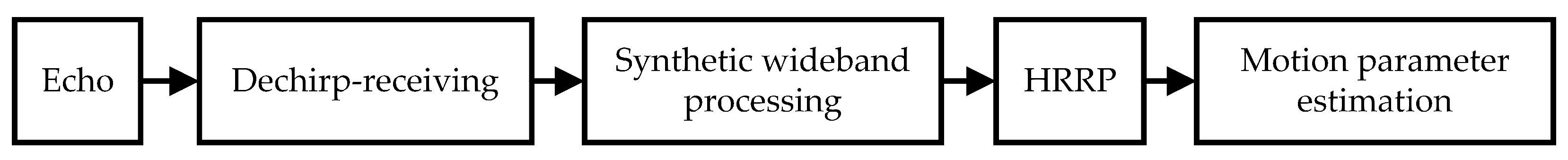
2. An Algorithm Based on Stepped DGRFT for Estimating Motion Parameters and HRRP Focusing
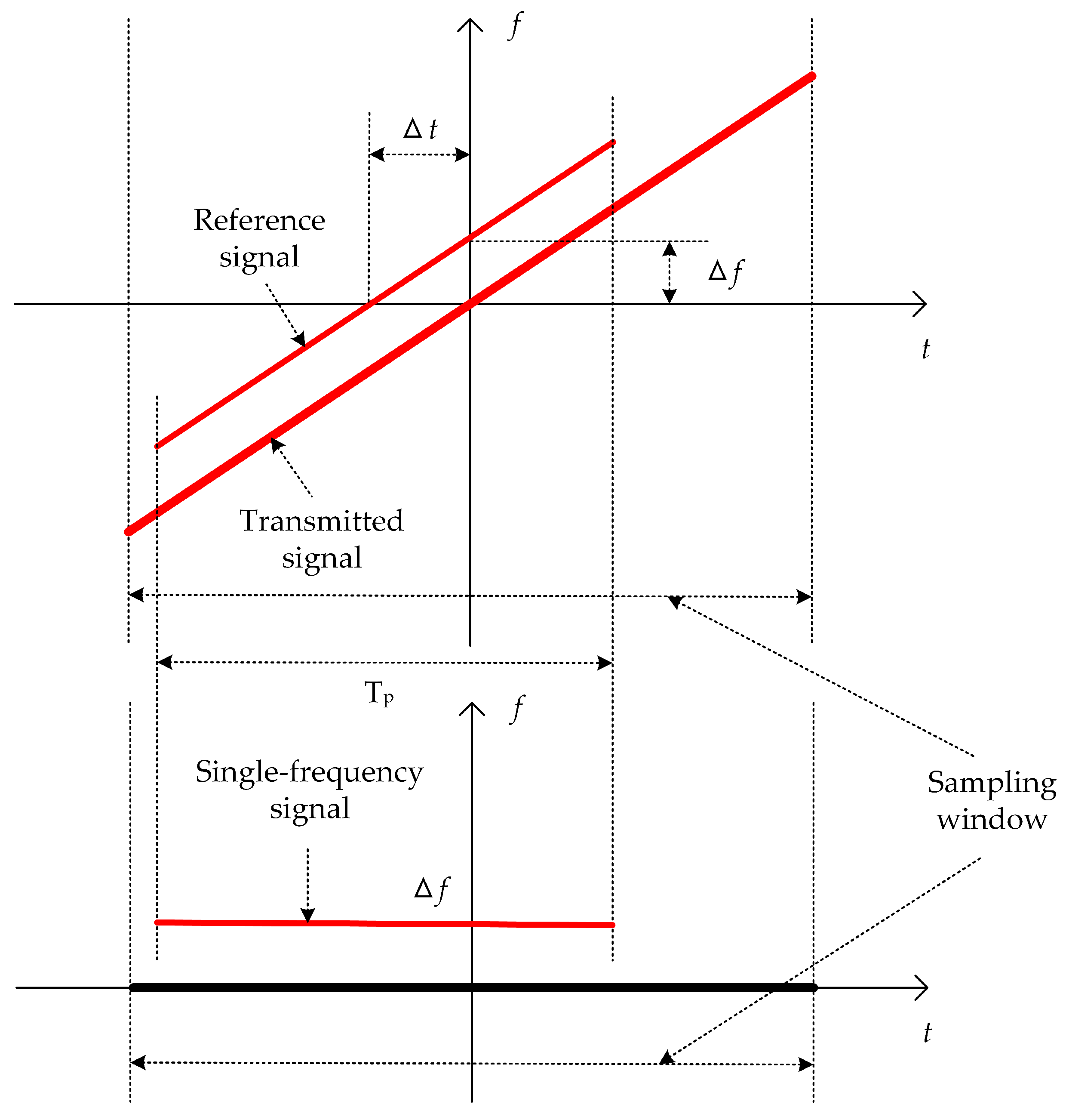
2.1. Principle of Dechirp Receiving
The dechirp-receiving technique employs a linear frequency-modulated (LFM) signal that is coherent with the frequency of the transmitted signal for the purpose of downconversion. In this downconversion stage, the echo is multiplied by the conjugate of the reference signal in the time domain. The dechirping process effectively eliminates the frequency modulation present in the LFM echo, subsequently narrowing the signal bandwidth. This facilitates operation at a reduced sampling frequency while still accommodating the transmission of signals with large bandwidths.
The frequency modulation slope of the transmitted signal is denoted by k, the original bandwidth of the signal is denoted by B, the pulse width is denoted by , and denotes the stepped-frequency interval. The echo received after dechirping can be approximated as a single-frequency signal, as shown in Figure 3.
Figure 3.
Single-frequency echo produced by dechirping.
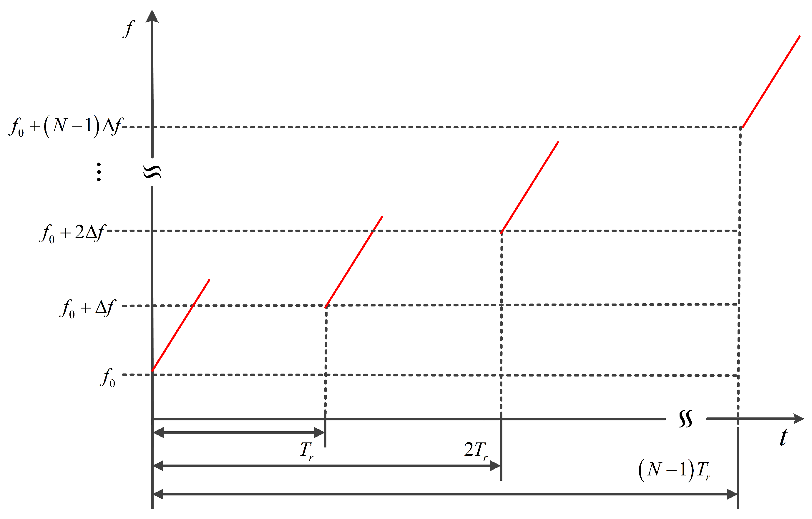
2.2. Principle of the Stepped DGRFT Algorithm
The dechirp-receiving stepped-frequency transmitted radar signal can be expressed as
where is the subpulse number, m is the frame number (), M is the total number of frames used for coherent accumulation, N is the number of subpulses in each frame of the echo, and h is the sequence number of the subpulse in the frame. is the fast time, is the pulse width, and . is the frequency modulation slope. is the carrier frequency of each subpulse (); is the initial carrier frequency. is the stepped-frequency interval, is the pulse repetition period (PRT), and the accumulation time is .
Within a single-point target scenario, the target motion parameters of each order are represented by the set , where , , , …, denote the initial radial range, initial velocity, initial acceleration, etc., of the target. The slow time can be expressed as . Then, the instantaneous radial range of the target can be expressed as
where is the slow time and K is the order of motion parameters.
The stop-and-go model can be used to obtain the target echo after downconversion to the baseband as
where is the amplitude factor of the target echo, which is assumed to remain unchanged between pulses in the same CPI, and c is the speed of light. The following reference signal is used for dechirping:
where is the reference range. The downconversion process consists of multiplying the echo by the conjugate of the reference signal in the time domain, where the dechirp-receiving echo can be expressed as
In the formula above, the first phase term is the range phase produced by dechirping that changes linearly with the instantaneous radial range of the target ; the second term is the azimuth phase that changes with , namely, the Doppler phase history; and the third term is the RVP term. Figure 4 shows the time–frequency relationship of the dechirp-receiving stepped-frequency signal. To elaborate, each subpulse transmits a wideband LFM signal, which is subsequently processed using dechirping. In the intervals between these pulses, frequency hopping takes place.
Figure 4.
Time–frequency relationship of the dechirp-receiving stepped-frequency signal.
To achieve effective coherent accumulation of multiframe signals, it is necessary to compensate the term in (5), where the corresponding filter bank, namely, the phase compensation factor, is
Then, the modified DGRFT algorithm for the dechirp-receiving stepped-frequency signal can be obtained as
where is the fast-time frequency and is the fast time sampling frequency.
The echo produced by dechirping is subjected to the fast Fourier transform (FFT) in the time domain to obtain the HRRP of the target after compensation through the filter bank . After compensation using the filter bank, the peaks of the HRRPs of all the dechirped subpulses are aligned to the reference distance. By traversing and searching the target motion parameters, we obtain the coherent accumulation output of the target echo. If and only if the set of search parameters satisfies , the output is largest at the reference distance after HRRPs in (7) are coherently superimposed; that is, complete coherent accumulation of the target is achieved. Each group of parameters in the search parameter set corresponds to the value at the reference distance after accumulation. Peak detection is performed on the resulting matrix to accurately estimate the target motion parameters in the parameter search space. Unlike classical DGRFT, the proposed DGRFT algorithm for modifying the dechirp-receiving stepped-frequency signal defined by (7) considers the hopping characteristics of the carrier frequency between the pulses of the dechirp-receiving stepped-frequency signal and is therefore named stepped DGRFT.
For most application scenarios, the radial target velocity can be regarded as constant during the accumulation time. In this case, only the initial radial range and of the target need to be estimated. The stepped DGRFT algorithm is thus simplified to stepped dechirp Radon–Fourier transform (stepped DRFT) as
where
is the degenerated filter bank, r is the initial radial range of the target, and v is the radial velocity.
2.3. Discretized Stepped DRFT
Let the search range of the initial radial range of the target be . For time-domain windowed data, usually and , where is the range gate length. The velocity search range is . As the coherent accumulation time is , the Doppler resolution of the Doppler frequency filter [19] can be expressed as
Therefore, the maximum velocity search interval can be obtained as
where the velocity search interval decreases with increasing carrier frequency. For the convenience of calculation, the following velocity search interval is selected:
where is the average carrier frequency. Then, the velocity search number can be obtained as
where round() represents a rounding operation.
For a given system sampling rate , the range search interval is
Therefore, the number of range searches is
The velocity dimension and range dimension search vector can be expressed as [19]
Substituting (16) into (9) yields the discretized phase compensation factor
where is the fast time sampling point.
After the radar echo is processed by the discretized stepped DRFT, the resulting matrix output is subjected to coherent superposition within the reference range, and then maximum detection is performed to obtain the estimated target motion parameters and .
2.4. A Dechirp-Receiving Stepped-Frequency Imaging Algorithm Based on Time-Domain Splicing and Synthesis
Dechirp-receiving stepped-frequency imaging algorithms are primarily categorized into spectrum splicing and time-domain splicing techniques. The spectrum splicing approach involves initially multiplying the dechirped echo at a singular frequency point with the reference signal utilized for dechirping. This produces the original wideband echo, also referred to as the directly sampled signal. Subsequently, this signal undergoes intrapulse first-order Doppler compensation. Thereafter, spectrum splicing across multiple frequency points is employed to generate an ultrawideband signal. In contrast, time-domain splicing imaging offers greater convenience compared to spectrum splicing imaging. The latter encompasses a more intricate procedure and presents numerous challenges in applications. The procedure for time-domain splicing imaging is described below. The target is assumed to be stationary to simplify the analysis. Using (5), the local dechirped baseband echoes of the i-th and (i + 1)-th subpulses are
We let and . As . The local dechirped baseband echo processed by time-domain delayed splicing is
Comparing (19) and (21) reveals that time-domain splicing changes the time-domain pulse width of the local dechirped processed baseband echo from the original value of to . When , i.e., , according to the principle of dechirping, the equivalent bandwidth is .
The analysis presented above demonstrates that for multiple subpulses, time-domain splicing yields the following baseband echo of the dechirp-receiving stepped-frequency ultrawideband signal:
Equation (22) indicates that the equivalent bandwidth after time-domain splicing and synthesis is . Note that the motion of the echo envelope and the quadratic phase term caused by the target motion considerably affect each dechirped subpulse, making it necessary to finely compensate for the synthesized echo using a high-precision velocity measurement before performing time-domain splicing and synthesis to enhance the imaging quality.
2.5. Motion Compensation and HRRP Focusing
Correct motion compensation is a prerequisite for HRRP focusing. The motion parameters estimated using stepped DGRFT are used to perform motion compensation of the maneuvering weak target in the time-domain:
Next, extraction-based time-domain splicing is used to synthesize the wideband to yield the HRRP of each frame signal. As the target is weak with a low SNR, the HRRPs of M frames of signals must be summed in the slow time dimension, thus achieving the HRRP after coherent accumulation; that is, the HRRP of the maneuvering weak target is focused.
3. Simulation Verification and Analysis
The proposed stepped DGRFT method is verified and the algorithm performance is comparatively analyzed against that of existing DGRFT methods by performing simulation experiments on two scenarios: target maneuvering motion with a constant velocity and constant acceleration.
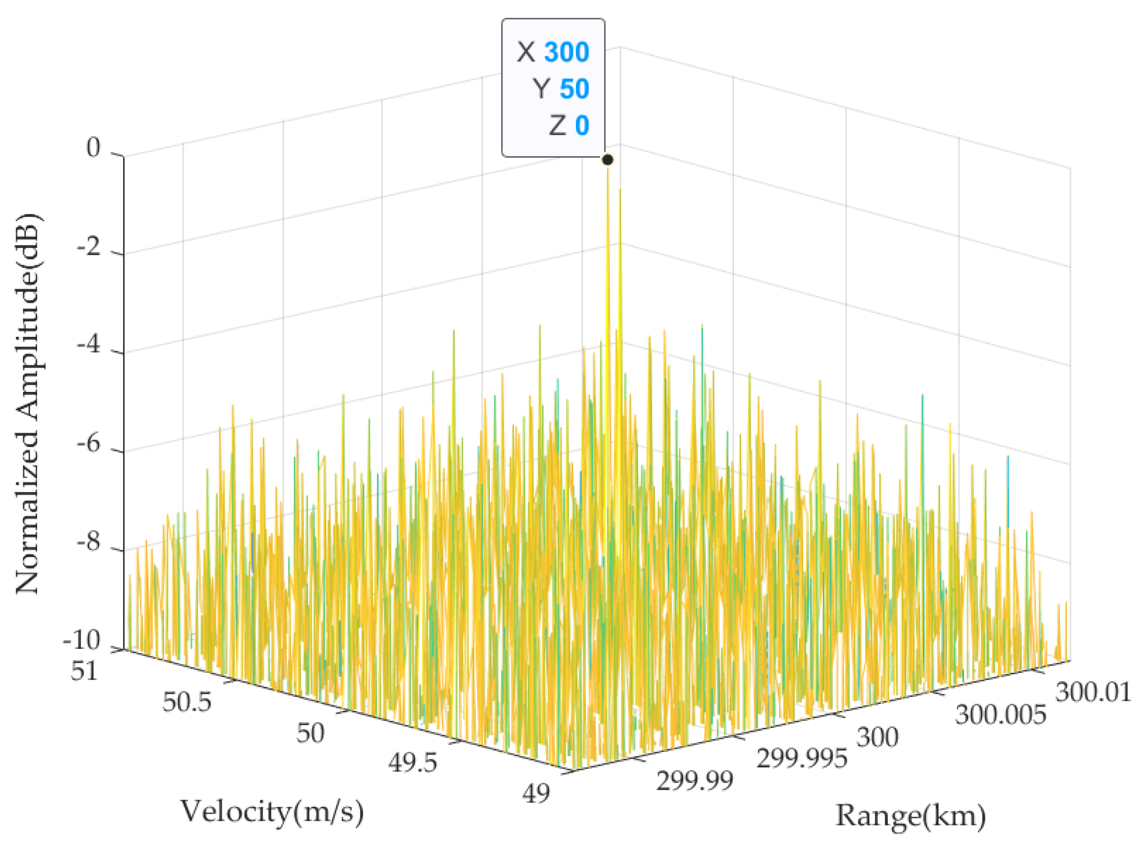
3.1. Algorithmic Performance Analysis for a Target with a Constant Velocity
3.1.1. Simulation Parameters
Table 1 shows the main parameters and target characteristics of the simulated radar system. To carry out a detailed comparison of the performances of the stepped DRFT and conventional DRFT algorithms, the signal carrier frequency in the simulation was set to hop linearly at a fixed stepped-frequency interval within a step cycle. The target moved at a constant velocity and consisted of two equal-intensity scattering points with initial radial ranges of 300 km and 300.000625 km. The target spanned a total of 12 range units throughout the entire accumulation period, and there was a clear ARU phenomenon. To endow the target with weak characteristics, Gaussian white noise was added to the echo such that the dechirp-receiving FFT yielded an echo with an SNR of −10 dB.
Table 1.
Simulation parameters.
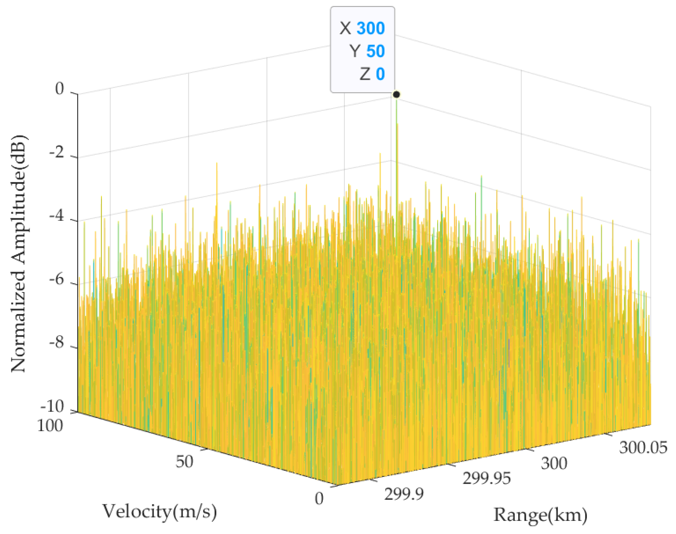
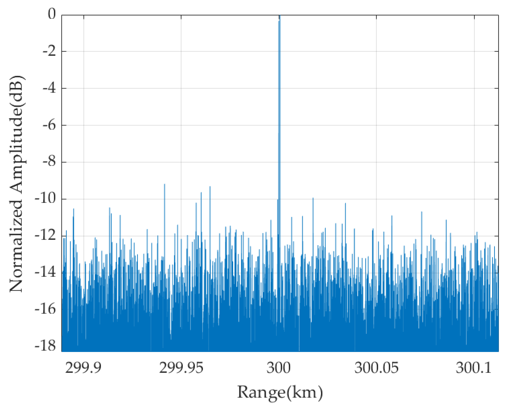
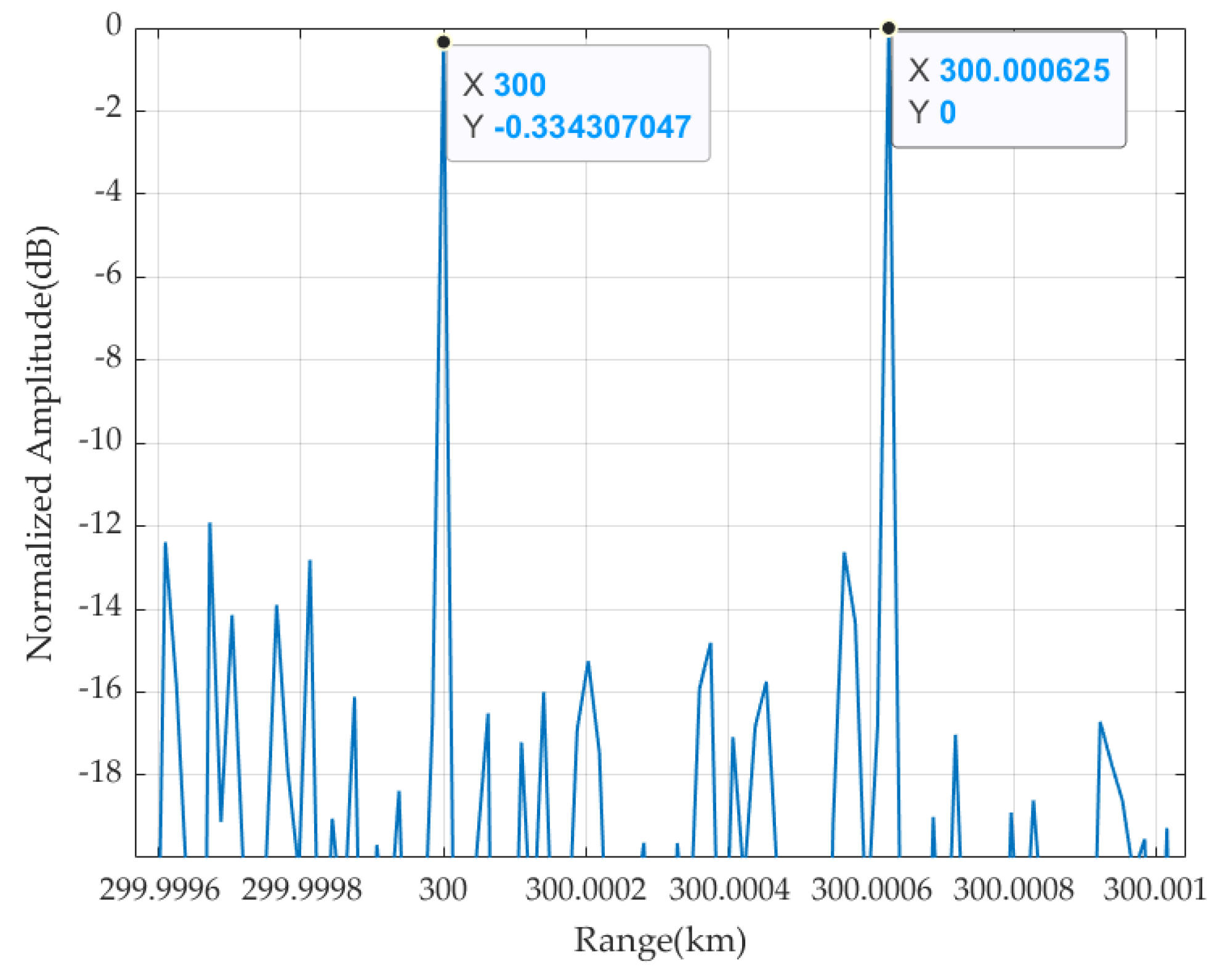
3.1.2. Performance Analysis of Stepped DRFT and Conventional DRFT
The velocity search range for stepped DRFT and conventional DRFT was set from 0 m/s to 200 m/s. Figure 5 shows the estimated target motion parameters obtained using the stepped DRFT algorithm (the estimated target velocity is 50 m/s with an error of 0 m/s). Figure 6 and Figure 7 show the target HRRP obtained after motion compensation, time-domain splicing, synthetic wideband processing, and coherent accumulation. The results indicate that the proposed algorithm achieves accurate estimation and compensation of the target parameters. For the target HRRP obtained after coherent accumulation, the positions of the two scattering points of the target are accurate with an amplitude difference of approximately 0.07 dB. Therefore, the HRRP is well-focused.
Figure 5.
Target motion parameters estimated using the stepped DRFT algorithm.
Figure 6.
HRRP-focusing results obtained using the stepped DRFT algorithm.
Figure 7.
Magnified view of the HRRP focusing results obtained using the stepped DRFT algorithm.
For conventional DRFT, synthetic wideband processing without motion compensation was first used to obtain the target HRRP, which was then accumulated over a long period of time using the DRFT. Figure 8 shows the target motion parameters estimated using the DRFT algorithm. The estimated target velocity is 44.32 m/s with an error of 5.68 m/s. Figure 9 shows the target HRRP obtained after motion compensation, time-domain splicing, synthetic wideband processing and coherent accumulation. The following results were obtained using conventional DRFT: the two scattering points of the target were submerged in noise, the two HRRP peaks appeared at 300.061714 km and 299.983333 km, and the HRRP was not correctly focused.
Figure 8.
Target motion parameters estimated using the conventional DRFT algorithm.
Figure 9.
HRRP-focusing results obtained using the conventional DRFT algorithm.
In summary, based on our use of a stepped-frequency transmitted signal and dechirp receiving for a constant-velocity target, the proposed stepped DRFT algorithm outperforms the conventional DRFT algorithm in terms of the estimation accuracy of the target motion parameters and the HRRP-focusing effect.
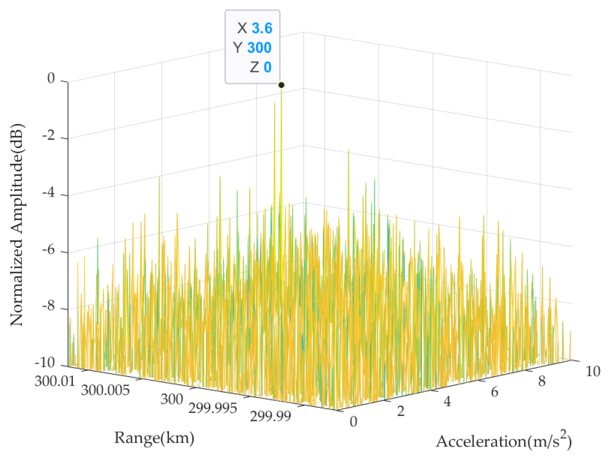
3.2. Algorithmic Performance Analysis for a Target under Constant Acceleration
3.2.1. Simulation Parameters
Table 2 shows the main parameters and target characteristics used for the simulated radar system. The performances of the stepped DGRFT and conventional DGRFT algorithms were compared in detail for a target under constant acceleration. The target consisted of two equal-intensity scattering points with initial radial ranges of 300 km and 300.000625 km. The target spanned a total of 12 range units over the entire accumulation period, and there was a clear ARU phenomenon. The target was endowed with weak characteristics by adding Gaussian white noise to the echo such that the dechirp-receiving FFT yields an echo with an SNR of −10 dB.
Table 2.
Simulation parameters.
3.2.2. Performance Analysis of Stepped DGRFT and Conventional DGRFT
For stepped DGRFT and conventional DGRFT, the velocity search range was set to 0–200 m/s, and the acceleration search range was set to −10 to 10 m/s. Figure 10 and Figure 11 show the target motion parameters estimated using stepped DGRFT. The initial target velocity is estimated at 50 m/s with an error of 0 m/s, and the target acceleration is estimated at 3.6 m/s with an error of 0 m/s. Figure 12 and Figure 13 show the target HRRPs obtained after motion compensation, time-domain splicing, synthetic wideband processing, and coherent accumulation. The results indicate that the proposed algorithm achieves accurate estimation and compensation of the target parameters. In the target HRRP obtained after coherent accumulation, the two scattering points of the target are accurately located with an amplitude difference of approximately 0.33 dB. Therefore, the HRRP is well-focused.
Figure 10.
Target motion parameters estimated using the stepped DGRFT algorithm plotted on the range–velocity plane.
Figure 11.
Target motion parameters estimated using the stepped DGRFT algorithm plotted on the acceleration-range plane.
Figure 12.
HRRP focusing results obtained using the stepped DGRFT algorithm.
Figure 13.
Magnified view of the HRRP focusing results obtained using the stepped DGRFT algorithm.
Figure 14 and Figure 15 show the target motion parameters estimated by the DGRFT algorithm. The initial target velocity is estimated at 18.97 m/s with an error of 31.03 m/s, and the target acceleration is estimated at 9.10 m/s with an error of 4.10 m/s. Figure 16 shows the target HRRP obtained after motion compensation, time-domain splicing, synthetic wideband processing, and coherent accumulation. The following results were obtained using the conventional DGRFT algorithm: the two scattering points of the target were submerged in noise, and the two peaks of HRRP appeared at 300.090351 km and 300.115840 km. Therefore, the HRRP was not correctly focused.
Figure 14.
Target motion parameters estimated using the conventional DGRFT algorithm plotted on the range–velocity plane.
Figure 15.
Target motion parameters estimated using the conventional DGRFT algorithm plotted on the acceleration–range plane.
Figure 16.
HRRP focusing results obtained using the conventional DGRFT algorithm.
In summary, based on a stepped-frequency transmitted signal and dechirp receiving for maneuvering constant-acceleration targets, the proposed stepped DGRFT algorithm outperforms conventional DGRFT in terms of the estimation accuracy of motion parameters and HRRP focusing.
4. Measured Data Verification and Analysis
4.1. Measured Data Parameters
The proposed stepped DGRFT algorithm was verified for use in practical applications by performing experiments and analyzing the measured data. The experiments were carried out using a Ka-band radar, a stepped-frequency transmitted signal, an instantaneous bandwidth of the subpulse of the stepped-frequency signal of 2 GHz, dechirp receiving, and a civil aircraft as the detection target. A weak target was simulated by adding Gaussian white noise to the measured data such that the dechirped echo after transformation to the frequency domain had an SNR of −10 dB. The target did not move at a constant velocity during the observation period and could be approximated as a maneuvering target because of high-order motion parameters. Table 3 shows the main parameters and target characteristics of the radar system used in the experiment. The target spanned a total of 18 range units over the entire accumulation period, and there was a clear ARU phenomenon.
Table 3.
Measured data parameters.
4.2. Performance Analysis of Stepped DGRFT and Conventional DGRFT
For stepped DGRFT and conventional DGRFT, the velocity search range was set to 0–200 m/s, and the acceleration search range was set to −10 to 10 m/s. Figure 17 and Figure 18 show the target motion parameters estimated using the stepped DGRFT algorithm. The initial target velocity was estimated at 49.639 m/s, and the target acceleration was estimated at −2.528 m/s. The estimated motion parameters were used to perform motion compensation on the target. Figure 19 and Figure 20 show the target HRRP obtained after motion compensation, time-domain splicing, synthetic wideband processing, and coherent accumulation, where the target position was 18.107392 km. No noise was added to the measured data, and the target ranging method based on the peak points was used to measure the target. The initial range of the target obtained by fitting is 18.107981 km. The fitted ranging results are shown in Figure 21. The proposed algorithm achieves accurate estimation and compensation of the target parameters. The main scattering point of the target HRRP obtained after coherent accumulation is accurately located, and the HRRP is well focused.
Figure 17.
Target motion parameters estimated using the stepped DGRFT algorithm plotted on the range–velocity plane.
Figure 18.
Target motion parameters estimated using the stepped DGRFT algorithm plotted on the acceleration–range plane.
Figure 19.
HRRP focusing results obtained using the stepped DGRFT algorithm.
Figure 20.
Magnified view of the HRRP focusing results obtained using the stepped DGRFT algorithm.
Figure 21.
Target ranging results obtained using peak points.
Figure 22 and Figure 23 show the target motion parameters estimated using conventional DGRFT: the initial target velocity was estimated at 86.19 m/s, and the target acceleration was estimated at −2.73 m/s. Figure 24 shows the target HRRP obtained after motion compensation, time-domain splicing, synthetic wideband processing, and coherent accumulation. The following results were obtained using conventional DGRFT: the signal of the target civil aircraft is submerged in noise, and an HRRP peak appears at 18.192220 km, which differs by 84.24 m from the result obtained using the target ranging method based on the peak points with no added noise. Therefore, the HRRP is not properly focused.
Figure 22.
Target motion parameters estimated using the conventional DGRFT algorithm plotted on the range–velocity plane.
Figure 23.
Target motion parameters estimated using the conventional DGRFT algorithm plotted on the acceleration–range plane.
Figure 24.
HRRP focusing results obtained using conventional DGRFT.
Figure 25 shows the detection probabilities of targets at varying SNRs using both the stepped DGRFT and traditional DGRFT algorithms. From the figure, it is evident that the stepped DGRFT algorithm achieves a detection probability exceeding 0.8 when the SNR is above −13 dB. Furthermore, its detection probability reaches 1 when the SNR is higher than −10 dB. On the other hand, the traditional DGRFT algorithm can only attain a detection probability of 0.8 when the SNR surpasses −2 dB.
Figure 25.
Detection probabilities with different SNRs.
5. Discussion
Based on the analysis of measured data, it is evident that the proposed algorithm, which employs a transmitted stepped-frequency signal paired with dechirp receiving, offers superior performance over conventional DGRFT in estimating target motion parameters and in focusing the target’s HRRP. The stepped DGRFT algorithm can achieve stable detection of the target when the SNR is above -10dB. The conventional DGRFT method relies on the coherent accumulation of HRRP following synthetic wideband processing. This approach fails to effectively compensate for distortions in the range profile arising from target motion. Consequently, there is a notable reduction in the target’s SNR after coherent accumulation. Such diminished SNR subsequently leads to the echo being overwhelmed by noise, making it less distinguishable.
6. Conclusions
In this study, we introduce the stepped DGRFT algorithm for dechirp-receiving stepped-frequency radar. This algorithm achieves long-term coherent accumulation, accurately estimates the motion parameters of maneuvering weak targets, and enhances the focusing of HRRP. We conduct a comparative analysis to evaluate the performance of the stepped DGRFT and conventional DGRFT in terms of motion parameter compensation and HRRP focusing. The effectiveness and superiority of the proposed algorithm over conventional DGRFT are verified through simulations and measurements. Our results demonstrate that the stepped DGRFT algorithm significantly improves the imaging capability of dechirp-receiving stepped-frequency radar for maneuvering weak targets.
Author Contributions
Conceptualization, Y.S.; methodology, Y.S. and Q.L.; software, Y.S., S.C. and Q.L.; validation, Q.L.; formal analysis, Y.S. and Q.L.; investigation, Q.L.; resources, S.C.; data curation, Y.S. and Q.L.; writing—original draft preparation, Y.S.; writing—review and editing, S.C., B.C., Q.L. and D.W.; visualization, Y.S.; supervision, S.C. and B.C.; project administration, S.C.; funding acquisition, S.C. All authors have read and agreed to the published version of the manuscript.
Funding
This research was funded by the Beijing Institute of Technology Research Fund Program for Young Scholars (Grant No. XSQD202205012) and the Natural Science Foundation of Chongqing, China (Grant No. cstc2020jcyj-msxmX0260).
Data Availability Statement
Not applicable.
Conflicts of Interest
The authors declare no conflict of interest.
References
- Huang, P.; Xia, X.; Liao, G.; Yang, Z.; Zhang, Y. Long-Time Coherent Integration Algorithm for Radar Maneuvering Weak Target with Acceleration Rate. IEEE Trans. Geosci. Remote Sens. 2019, 57, 3528–3542. [Google Scholar] [CrossRef]
- Chen, X.; Guan, J.; Chen, W.; Zhang, L.; Yu, X. Sparse Long-Time Coherent Integration–Based Detection Method for Radar Low-Observable Maneuvering Target. IET Radar Sonar Navig. 2020, 14, 538–546. [Google Scholar] [CrossRef]
- Gao, C.; Tao, R.; Kang, X. Weak Target Detection in the Presence of Sea Clutter Using Radon-Fractional Fourier Transform Canceller. IEEE J. Sel. Top. Appl. Earth Obs. Remote Sens. 2020, 14, 5818–5830. [Google Scholar] [CrossRef]
- Xu, S.Z.; Kooij, B.J.; Yarovoy, A. Joint Doppler and DOA estimation using (Ultra-)Wideband FMCW signals. Signal Process. 2020, 168, 107259. [Google Scholar] [CrossRef]
- Pan, M.; Liu, A.; Yu, Y.; Wang, P.; Li, J.; Liu, Y.; Lv, S.; Zhu, H. Radar HRRP target recognition model based on a stacked CNN–Bi-RNN with attention mechanism. IEEE Trans. Geosci. Remote Sens. 2022, 60, 1–14. [Google Scholar] [CrossRef]
- Xue, B.; Zhang, G.; Leung, H.; Dai, Q.; Fang, Z. An Applied Ambiguity Function Based on Dechirp for MIMO Radar Signal Analysis. IEEE Trans. Geosci. Remote Sens. Lett. 2022, 19, 4021005. [Google Scholar] [CrossRef]
- Wang, L.; Huang, T.; Liu, Y. Phase Compensation and Image Autofocusing for Randomized Stepped Frequency ISAR. IEEE Sens. J. 2019, 19, 3784–3796. [Google Scholar] [CrossRef]
- Li, W.J.; Fan, H.Y.; Ren, L.X.; Mao, E.K.; Liu, Q.H. A High-Accuracy Phase-Derived Velocity Measurement Method for High-Speed Spatial Targets Based on Stepped-Frequency Chirp Signals. IEEE Trans. Geosci. Remote Sens. 2021, 59, 1999–2014. [Google Scholar] [CrossRef]
- Liu, S.; Cao, Y.; Yeo, T.; Wang, F.; Han, J. Range Sidelobe Suppression for Randomized Stepped-Frequency Chirp Radar. IEEE Trans. Aerosp. Electron. Syst. 2021, 57, 3874–3885. [Google Scholar] [CrossRef]
- Liu, M.; Chen, J. Synthesizing of Stretched Chirp-Step Signal: Theory and Application Techniques. Electron. Opt. Control 2019, 26, 71–75. [Google Scholar]
- Pang, C.; Liu, S.; Han, Y. Coherent detection algorithm for radar maneuvering targets based on discrete polynomial-phase transform. IEEE J. Sel. Top. Appl. Earth Obs. Remote Sens. 2019, 12, 3412–3422. [Google Scholar] [CrossRef]
- Zhang, S.; Zhou, Y.; Zhang, L.; Zhang, Q.; Du, L. Target Detection for Multistatic Radar in the Presence of Deception Jamming. IEEE Sens. J. 2021, 21, 8130–8141. [Google Scholar] [CrossRef]
- Perry, R.; DiPietro, R.; Fante, R. SAR Imaging of Moving Targets. IEEE Trans. Aerosp. Electron. Syst. 1999, 35, 188–200. [Google Scholar] [CrossRef]
- Fang, X.; Li, J.; Zhang, Z.; Xiao, G. FMCW-MIMO Radar-Based Pedestrian Trajectory Tracking Under Low-Observable Environments. IEEE Sens. J. 2022, 22, 19675–19687. [Google Scholar] [CrossRef]
- Ding, T.; Zhang, J.; Tang, S.; Zhang, L.; Li, Y. A Novel Iterative Inner-Pulse Integration Target Detection Method for Bistatic Radar. IEEE Trans. Geosci. Remote Sens. 2022, 60, 5114915. [Google Scholar] [CrossRef]
- Yuan, Z.; Wang, J.; Zhao, L.; Gao, M. An MTRC-AHP Compensation Algorithm for Bi-ISAR Imaging of Space Targets. IEEE Sens. J. 2020, 20, 2356–2367. [Google Scholar] [CrossRef]
- Liang, M.; Su, W.; Gu, H. Focusing High-Resolution High Forward-Looking Bistatic SAR with Nonequal Platform Velocities Based on Keystone Transform and Modified Nonlinear Chirp Scaling Algorithm. IEEE Sens. J. 2018, 19, 901–908. [Google Scholar] [CrossRef]
- Deng, T.D.; Jiang, C.S. Evaluations of Keystone Transforms Using Several Interpolation Methods. In Proceedings of the 2011 IEEE CIE International Conference on Radar, Chengdu, China, 24–27 October 2011; Volume 2, pp. 1876–1878. [Google Scholar]
- Xu, J.; Yu, J.; Peng, Y.; Xia, X.G. Radon–Fourier Transform for Radar Target Detection, I: Generalized Doppler Filter Bank. IEEE Trans. Aerosp. Electron. Syst. 2011, 47, 1186–1202. [Google Scholar] [CrossRef]
- Qian, L.; Xu, J.; Xia, X.; Sun, W.; Long, T.; Peng, Y. Wideband-Scaled Radon-Fourier Transform for High-Speed Radar Target Detection. IET Radar Sonar Navig. 2014, 8, 501–512. [Google Scholar] [CrossRef]
- Xu, J.; Yan, L.; Zhou, X.; Long, T.; Xia, X.-G.; Wang, Y.-L.; Farina, A. Adaptive Radon-Fourier Transform for Weak Radar Target Detection. IEEE Trans. Aerosp. Electr. Syst. 2018, 99, 686–697. [Google Scholar] [CrossRef]
- Li, X.; Sun, Z.; Yeo, T.S. Computational Efficient Refocusing and Estimation Method for Radar Moving Target with Unknown Time Information. IEEE Trans. Comput. Imag. 2016, 2, 13–26. [Google Scholar] [CrossRef]
- Li, X.; Sun, Z.; Zhang, T.; Yi, W.; Cui, G.; Kong, L. Computational Efficient Refocusing and Estimation Method for Radar Moving Target with Unknown Time Information. Signal Process. 2020, 166, 544–557. [Google Scholar] [CrossRef]
- Xia, L.; Gao, H.; Liang, L.; Lu, T.; Feng, B. Radar Maneuvering Target Detection Based on Product Scale Zoom Discrete Chirp Fourier Transform. Remote Sens. 2023, 15, 1792. [Google Scholar] [CrossRef]
- Zhao, Z.; Zhang, Y.; Wang, W.; Liu, B.; Wu, W. Long-Time Coherent Integration for Marine Targets Based on Segmented Compensation. Remote Sens. 2023, 15, 4530. [Google Scholar] [CrossRef]
- Liu, Q.; Guo, J.; Liang, Z.; Long, T. Motion Parameter Estimation and HRRP Construction for High-Speed Weak Targets Based on Modified GRFT for Synthetic-Wideband Radar with PRF Jittering. IEEE Sens. J. 2021, 21, 23234–23244. [Google Scholar] [CrossRef]
- You, P.; Ding, Z.; Liu, S.; Zhang, G. Dechirp-receiving Radar Target Detection Based on Generalized Radon-Fourier Transform. IET Radar Sonar Navig. 2021, 15, 1096–1111. [Google Scholar] [CrossRef]
Disclaimer/Publisher’s Note: The statements, opinions and data contained in all publications are solely those of the individual author(s) and contributor(s) and not of MDPI and/or the editor(s). MDPI and/or the editor(s) disclaim responsibility for any injury to people or property resulting from any ideas, methods, instructions or products referred to in the content. |
© 2023 by the authors. Licensee MDPI, Basel, Switzerland. This article is an open access article distributed under the terms and conditions of the Creative Commons Attribution (CC BY) license (https://creativecommons.org/licenses/by/4.0/).