Abstract
Due to a lack of geographical reference information, complex panoramic camera models, and intricate distortions, including radiation, geometric, and land cover changes, it can be challenging to effectively apply the large number (800,000+) of high-resolution Corona KH-4B panoramic images from the 1960s and 1970s for surveying-related tasks. This limitation hampers their significant potential in the remote sensing of the environment, urban planning, and other applications. This study proposes a method called 2OC for the automatic and accurate orientation and orthorectification of Corona KH-4B images, which is based on generalized control information from reference images such as Google Earth orthophoto. (1) For the Corona KH-4B panoramic camera, we propose an adaptive focal length variation model that ensures accuracy and consistency. (2) We introduce a robust multi-source remote sensing image matching algorithm, which includes an accurate primary orientation estimation method, a multi-threshold matching enhancement strategy based on scale, orientation, and texture (MTE), and a model-guided matching strategy. These techniques are employed to extract high-accuracy generalized control information for Corona images with significant geometric distortions and numerous weak texture areas. (3) A time-iterative Corona panoramic digital differential correction method is proposed. The orientation and orthorectification results of KH-4B images from multiple regions, including the United States, Russia, Austria, Burkina Faso, Beijing, Chongqing, Gansu, and the Qinghai–Tibet Plateau in China, demonstrate that 2OC not only achieves automation but also attains a state-of-the-art level of generality and accuracy. Specifically, the standard deviation of the orientation is less than 2 pixels, the mosaic error of orthorectified images is approximately 1 pixel, and the standard deviation of ground checkpoints is better than 4 m. In addition, 2OC can provide a longer time series analysis of data from 1962 to 1972, benefiting various fields such as environmental remote sensing and archaeology.
1. Introduction
The Corona program, as a reconnaissance satellite initiative aimed at acquiring military strategic and weapon intelligence, collected over 860,000 images of the Earth’s surface [,]. The highest-quality images from the Corona program, the KH-4B images [], have a resolution of 1.8 m, which can be used for the identification and mapping of historic road systems [], architectural structures [], and historic landscapes []. They are also valuable for studying urban expansion [], creating historical land cover maps [,], reconstructing historical ecological data [], and assessing glacier area changes []. Nevertheless, the original KH-4B images suffer from intricate panoramic geometric distortions due to the absence of georeferencing, preventing their direct use in scientific research. Moreover, because of complex distortions, such as radiation distortion, geometric distortion, land cover changes, and weak texture, the current georeferencing process for KH-4B imagery is achieved through expensive and time-consuming manual rectification, significantly limiting their practical utility.
In recent years, some scholars [] have attempted to fit the Corona panoramic camera model using traditional frame-based camera models to correct the panoramic distortions. However, the rectification accuracy of these methods is low because of significant differences in camera models. To address this issue, Jacobsen et al. [] proposed a perspective framework camera model that incorporates geometric panoramic transformation terms. This model was applied on a large scale and achieved an orientation mean error of approximately 11.4 pixels. A fisheye camera model was used by Lauer et al. [] to fit the panoramic distortions of Corona images, achieving a planimetric positioning accuracy of 17 m on local Corona images. Additionally, Sohn [] proposed the use of a second-order rational function model (RFM) to georectify Corona KH-4B images. However, the limited number of manually extracted generalized control points resulted in lower accuracy. Sohn [] also proposed two rigorous mathematical models, which are a modified projection model based on the frame-based model and a time-related exterior orientation elements projection model. The time-related exterior orientation elements projection model, as a complex and rigorous panoramic camera model, achieved sub-2-pixel orientation accuracy on a local region with around 30 manually extracted generalized control points. However, this camera model cannot adapt to focal length variations, and the experiments show that the official design focal length is not always optimal for all image orientations, leading to increased errors and even orientation failure. Furthermore, the aforementioned approaches had a significant drawback: the need for manual extraction of generalized control points []. We aim to automatically extract match points between KH-4B images and reference images using image matching techniques. However, traditional image matching techniques (such as SIFT [], SURF [], and UR-SIFT []) are unable to extract stable and accurate control information from Corona images due to the complexity of multiple distortions arising from differences in satellite orbits, sensor characteristics, and large temporal gaps. For instance, Bhattacharya et al. [] manually selected generalized control points and used remote sensing software (Graz) to generate a Corona KH-4B digital elevation model (DEM). These methods improve orientation accuracy with enhanced mathematical models but are only suitable for small datasets because of their reliance on manually extracted control information.
This study proposes a universal method, named 2OC, for the automatic orientation and orthorectification of Corona KH-4B images. First, a 14-parameter panoramic mathematical model and a time-iterative orthorectification technique are introduced to correct the panoramic geometric distortion and fit the focal length distortions of Corona panoramic images. Second, to address the complex distortions of Corona images, a robust image-matching method is proposed to extract correspondences between Corona images and reference images, generating generalized control points. Specifically, (1) A robust feature matching algorithm, NIFT, is proposed to estimate the transformation relationship between images, considering radiation and geometry distortions. (2) A multi-threshold matching enhancement strategy, MTE, is developed to optimize the distribution and quantity of generalized control points in areas with weak textures and land cover changes, thus improving the overall accuracy of the control information. (3) A model-guided matching strategy is introduced to reduce the impact of panoramic distortions.
The main contributions of this study are as follows:
- We propose an automatic orientation and orthorectification method (2OC) for Corona KH-4B images. To validate its effectiveness, we apply 2OC to a large number of multi-regional KH-4B images with various sources of references, and the detailed information is given in Table 1. The orientation accuracy is better than 2 pixels, the stitching error of orthorectified images is approximately 1 pixel, and the ground checkpoints have an RMSE accuracy better than 4 m. This demonstrates that 2OC is capable of processing KH-4B images with different regions, terrains, and image distortions using multiple reference images.
- We propose a 14-parameter corona panoramic camera model and a time-iterative panoramic orthorectification method. First, to address the focal length and panoramic distortions of KH-4B images, we propose a 14-parameter panoramic camera model. Second, to obtain an analytical solution for back-projecting ground coordinates to image coordinates, we propose a novel time-iterative panoramic orthorectification method.
- We introduce a robust control information extraction algorithm for extracting match points between KH-4B images and reference images to generate control information. To overcome land cover changes and geometric distortions (rotation, scale, panoramic), we propose a robust feature matching algorithm, a multi-threshold matching enhancement strategy (MTE) based on local texture, scale, and orientation, and a model-guided matching strategy.

Table 1.
The details of the KH-4B images and the reference images used in the experiments.
2. Related Work
In this section, we first provide an overview of current methods for processing Corona images and then briefly review the matching techniques for multi-source remote sensing images.
2.1. Geometric Processing of the Corona Images
Non-panoramic camera model-based methods: Altmaier et al. [] directly used frame-based image processing software (ERDAS IMAGE OrthoBASE Pro) to process Corona images, obtaining digital surface models with elevation and planimetric accuracy of 10 m and 3 m, respectively. Casana [] also used this method to process Corona images in the Middle East and achieved orientation errors of approximately 5 pixels within a small image size of less than 5000 × 5000 pixels. Nita et al. [] utilized match points between panoramic images for relative orientation, followed by absolute orientation using manually extracted generalized control points to generate DSMs and orthorectified images with a planimetric error of around 14 m. Rizayeva et al. [] applied the method presented in [] to produce orthorectified images with a resolution of 2.5 m and achieved a planimetric error of 16.3 ± 10.4 m. Furthermore, Bhattacharya et al. [] used Graz (RSG) software to process KH-4B images, resulting in a triangulation error of approximately 2.5 pixels. Moreover, Jacobsen et al. proposed a perspective framework camera model that incorporates panoramic transformation terms, but it exhibited a high standard deviation of 11.4 pixels in orientation. After all, non-panoramic camera models, although simple, suffer from lower accuracy.
Panoramic camera model-based methods: To better fit the Corona KH-4B panoramic camera, Sohn [] proposed two approaches: (1) modifying the panoramic camera model based on the differences between frame-based imaging and panoramic imaging models by analyzing their transformation equations, (2) developing a time-dependent panoramic camera model by analyzing the panoramic imaging process and considering camera and platform motions. Based on the manually extracted generalized control points, they achieved orientation accuracy of approximately 1.5 pixels for small-scale KH-4B images. Additionally, Shin and Schenk [] proposed a simplified panoramic camera model, assuming that the internal parameters of the camera only undergo motion along the sensor direction during exposure and the external parameters experience motion along the flight direction. They obtained a height error of approximately 12 m in Corona stereo pairs. Although the fisheye camera model is different from the Corona panoramic camera model, Lauer et al. [] attempted to apply the fisheye camera model to process Corona images and achieved a planimetric accuracy of approximately 17 m. These methods improve orientation accuracy with enhanced mathematical models but are only suitable for small datasets because of their reliance on manually extracted control information.
2.2. Image Matching Techniques
In recent years, scale-invariant feature transform (SIFT) [] has been widely used as a classical local feature extraction algorithm for image registration in remote sensing. However, the non-linear intensity distortion between multi-temporal and multi-sensor remote sensing images severely degrades the performance of SIFT. Therefore, Ye et al. proposed some region-based matching algorithms, such as HOPC [] and CFOG [], which have been successfully applied to multi-sensor image registration. These methods rely on prior information about the image position. To address this issue, Li et al. proposed feature-matching algorithms, namely RIFT [] and LNIFT [], which do not depend on prior location information. These algorithms exhibit good performance in combating non-linear radiometric distortion but have limited robustness regarding rotation and scale distortion. Additionally, with the rapid development of deep learning techniques, Ghuffar et al. [] employed the deep model Superglue [], designed for matching natural scene images, to automatically extract control information from Landsat images, achieving a sub-pixel level of median error. However, it cannot adapt well to the unique complex distortions in KH-4B images. Therefore, the current image-matching techniques are not robust enough to handle the complex distortions of KH-4B images for orientation and rectification tasks.
Based on this, 2OC is proposed for the orientation and orthorectification of Corona KH-4B images with complex distortions. First, a 14-parameter panoramic mathematical model and a digital differential orthorectification method are proposed to effectively fit the panoramic and focal length distortions of KH-4B images. Second, a robust image-matching algorithm is developed for the automatic extraction of control information. Extensive experimental results demonstrate that 2OC achieves orientation accuracy better than 2 pixels, with a mosaic error of approximately 1 pixel for orthorectified images and a median error of less than 4 m for ground checkpoints.
3. Corona KH-4B Image Processing
The 2OC process consists of multiple modules: a panoramic camera model, image orientation, orthorectification, and a generalized control information extraction algorithm. The detailed workflow is shown in Figure 1: First, the images are downsampled (❶), and a feature-matching algorithm is used to estimate the transformation matrix between KH-4B images and reference images (❷). Second, an image pyramid is constructed, and template matching (❸) and multi-threshold matching enhancement strategy (❸) are employed to obtain reliable match points (❹) for generating generalized control information (❹). Then, image orientation (❺) is performed, and model-guided matching (❻) is used to re-optimize the generalized control information (❻) and image orientation results (❼). Finally, the KH-4B orthorectified images are obtained using orthorectification based on iterative scanning time (❽).

Figure 1.
The flowchart of 2OC. M represents the transformation matrix between images, and GCP is the abbreviation for generalized control points.
3.1. Introduction of the Corona Images
As shown in Table 2, the Corona missions include KH-1, KH-2, KH-3, KH-4, KH-4A, and KH-4B. According to U.S. Executive Order 12951 [], these images were released to the National Archives and Records Administration (NARA) and the U.S. Geological Survey (USGS) on 23 February 1995. The complete panoramic image has a size of approximately 70 × 745 mm, and the USGS scanned the image at resolutions of 7 or 14 μm. However, due to the large size of the image, it was divided into four overlapping sections for scanning, labeled as a, b, c, and d, and generated four sub-images. Detailed information on Corona KH images is provided in Table 2.

Table 2.
The detailed information of KH images.
KH images have complex distortions, making them hard to process. (1) The Corona KH-4 camera rotates steadily in the across-track direction within an expansion of 70° while sequentially exposing a static film, obtaining a series of instantaneous strip images with significant panoramic distortions. (2) The KH-4B images may experience varying levels of deformation. Fortunately, the additional markings, panoramic geometry (PG) stripes, on the image can assist in evaluating the deformation. Specifically, during the photography process, the lamps mounted on the lens form straight lines at the edges of the image, as shown in Figure 2. Therefore, the PG stripes bend with film deformation. However, KH-4 and KH-4B images do not include PG stripes but rather feature shrinkage marks and format center indicators. (3) The scanning process of the image is not precisely calibrated, requiring the estimation of rotation and translation components using the overlapping areas of adjacent image blocks for accurate sub-image stitching. A previous study [] has shown that there are varying levels of block-wise deformations within the images, which can result in incorrect sub-image transformations. These errors accumulate during the stitching process, affecting the overall accuracy. Therefore, we process the sub-images separately before stitching to avoid stitching errors and correct scanning errors, considering that the interior and exterior orientation elements of image orientation compensate for the rotation and translation of sub-images.

Figure 2.
Schematic of film and PG reference data in KH-4B missions. All dimensions are in meters unless otherwise stated.
3.2. The Imaging Model of Corona KH-4B Panoramic Cameras
The imaging process of a KH-4B camera is depicted in Figure 3. While the satellite moves swiftly along its orbit, the camera rapidly rotates to sequentially expose the static film. This dynamic process results in time-varying exterior orientation elements of the camera. To better fit the imaging procedure of the KH-4B panoramic camera, a 14-parameter mathematical model is proposed. This model includes 12 exterior orientation elements associated with time, the dynamic correction parameter, and the image focal length. The derivation of the imaging model at any arbitrary time is provided below.
- (1)
- Exterior orientation of the KH-4B panoramic camera at time

Figure 3.
The imaging of KH-4B images. (a) The imaging process; (b) the imaging geometric relationship.
First, the change in exterior orientation elements, including position coordinate and orientation elements , caused by the satellite motion can be expressed using the following equations by assuming that they are linearly related to the time .
where and are the exterior orientation elements at time 0 and , where after normalization. are the variation coefficients with respect to . represents the coordinate of the instantaneous image on the panoramic image in the horizontal direction, represents the length of the film.
Second, we introduce a change in the exterior orientation elements caused by camera rotation along the cross-track direction with , which is elaborated in Figure 3b and can be expressed using Equation (8).
where is the rotation angle in the cross-track direction, and is the camera focal length.
Therefore, the exterior orientation elements of the camera at are }.
- (2)
- The imaging model of instantaneous strip images
Given that the instantaneous strip image width at time is extremely narrow, the instantaneous strip image satisfies the following collinearity equation:
where represents the scale factor, and are the rotation matrices caused by the camera rotation and satellite motion, respectively, where can be obtained using in Equations (4)–(6). are the coordinates of a ground point, is the vertical coordinate of the corresponding image point.
Furthermore, the rapid motion along the track direction of the camera will produce dynamic deformation in the vertical direction during the exposure process. Considering this, we employ a displacement to mitigate this deformation, which can be expressed using Equation (11).
where and represent the satellite’s velocity and orbit altitude, respectively. represents the angular velocity of the lens in the cross-track direction. Therefore, the imaging model can be described as follows.
By multiplying the left equation with
If we define , and as follows:
where represents the element at the i-th row and j-th column of the rotation matrix . Moreover, the scale factor can be eliminated by dividing the first and second rows of the equation by the third row of the Equation (14).
Then, we can obtain the panoramic camera coordinates () based on the following collinearity function.
After all, the relationship between the ground coordinates (, , and panoramic camera coordinates () can be modeled with the following 14 parameters: the camera’s initial exterior orientation parameters , coefficients for its linear variation over , image dynamic deformation coefficient , and the camera focal length .
3.3. Automated Orientation of Corona KH-4B Images Based on Generalized Control
We orient the KH-4B images by solving the 14 parameters using the generalized control points. Specifically, the image matching technique proposed in Section 4 is employed to automatically obtain a large number of well-distributed match points between KH-4B images and reference images. Here, we set the coordinates of a pair of match points as in the KH-4B image and in the reference image. Using the geographic information of the reference image, the object coordinates corresponding to can be obtained, and the elevation information can be obtained from the Digital Elevation Model (DEM). This results in the generalized control information .
Given that the imaging model has 14 parameters and each generalized control point can provide two equations, at least seven points are required to solve the parameters using Equations (20) and (21). When more generalized control points are available, these parameters can be solved using a least squares adjustment, which will enhance the calculation accuracy and reliability. Additionally, as the collinearity equations are non-linear, they must be linearized and require relatively accurate initial parameters.
However, Corona KH-4B images do not provide orientation parameters or auxiliary information that can be used to calculate the orientation parameters, such as the primary point coordinates, lens distortion coefficients, reference coordinates, satellite position, satellite velocity, and satellite attitude. As described in Section 3.1, we orient the sub-image separately instead of the whole image. Even though the primary point coordinates of the sub-image will deviate from the original photographic primary point; however, this deviation will be compensated by the external orientation elements of the pose parameters. In this study, the initial values of and are set to the average geographical coordinates (, ) of all generalized control points, is set to 170,000 m based on the satellite orbit, w is set to {−15°, 15°} based on the forward and backward perspectives. Focal length f is set to 0.609602 m based on a default value provided by [], and the other nine parameters are set to 0.
3.4. Orthorectification of KH-4B Panoramic Images Based on Iteration over Time
Orthorectification is the process of mapping image points from panoramic KH-4B images to orthophoto. First, we calculate the corresponding ground coordinates for the image point of orthophoto. Then, we compute the corresponding panoramic coordinates for ground point based on the imaging model and the solved 14 parameters. However, the solution of require the exposure time t and the exterior orientation elements at , which are unknown. To address the circular dependency problem, we formulate it as an optimization problem of minimizing an objective function . describes the error between and the panoramic image coordinates computed based on (), , and .
where represents the image coordinate point, is the length of the film, and are the scan time and rotation angle of the instantaneous strip image at , respectively. are the ground point coordinates, and and are the image coordinates calculated based on the time and ground point . To find the image coordinates that minimize the objective function , this study adopts an iterative approach to update the exterior orientation elements as well as the image coordinates.
The specific steps of the orthorectification process are as follows:
- (1)
- We create a grid for the orthorectified image based on the coverage range of the KH-4B image and the desired resolution , and interpolate the elevation values for the grid points using DEM.
- (2)
- We initially set to 0.5, to half of the film length and to 0 for each ground point.
- (3)
- We first calculate and based on and the solved 14 parameters. Then, we calculate the and of Equation (26) according to Equations (20) and (21). Finally, we adjust according to . Repeat this step until is minimized. We summarize the process in Algorithm 1.
- (4)
- We interpolate the grayscale values of on the KH-4 image and assign them to the orthorectified image.
Algorithm 1: The specific steps of orthorectification |
Input: ground point coordinates ; solved 14 parameters: ,,,,,, ,,,,,,,,; film length: . |
Output: . |
|
|
← |
←// is the Equations (20) and (21) |
←; , ←← |
← |
End |
|
4. Extraction of Generalized Control Information
Differences in satellite orbit, sensors, and acquisition times result in radiometric, rotational, and scale distortions and changes in ground features between KH-4B images and reference images. To address this issue, this section proposes a robust algorithm for extracting generalized control information.
4.1. Feature Matching of the Corona Image and the Reference Image
4.1.1. Multiscale GU-FAST Feature Detection
To address radiometric distortion and feature point clustering, a method called GU-FAST is proposed. Specifically, GU-FAST first detects edges using the Sobel [] operator and then applies the FAST algorithm with a low threshold to extract corner points ( > is the number of feature points to be detected), which are sorted based on the Harris [] score. Next, within a range of , where and are the width and height of the image, respectively, GU-FAST searches for neighboring points and removes them from the set. Finally, the top key points with the largest responses are selected. To handle scale distortion, a scale space is constructed based on [], and multiscale GU-FAST corner points are applied.
4.1.2. Rotation-Invariant Feature Description
Image rotation and non-linear radiometric distortion pose inevitable challenges in the matching of KH-4B images and references with non-linear intensity change, considering that the traditional feature description methods cannot handle non-linear intensity change and are sensitive to image rotation. To address this, a feature descriptor based on multi-directional features is proposed, which utilizes a multiscale, multi-directional Log–Gabor filter to construct multi-directional structural features (MR).
where represents the filter feature of Log–Gabor, where and denote the scale and orientation of the Log–Gabor filter, respectively. represents norm values.
A. Primary Orientation Estimation
Since the initial orientation of the Log–Gabor filter is fixed, the order of MR layers is highly sensitive to rotation distortion. Towards this, a primary orientation estimation algorithm based on the weighted norm feature of multiple-directional filtering is proposed. The specific algorithm follows the steps below:
- (1)
- Extract the norm values of a circular area around the feature point and apply Gaussian weighting to the area.
- (2)
- Identify evenly distributed multiple sectors with same-size overlapping regions within the circular area, as shown in Figure 4a. Specifically, we randomly create the first sector with a size of degrees, then rotate the sector sequentially by degrees clockwise. The adjacent sectors will have an overlapping of angles. In this study, we set and as 5 and 30, respectively, obtaining 72 sectors in total.
- (3)
- Calculate the sum of weighted norms of all pixels within a sector for all for each sector.
- (4)
- Find the sector with the largest norm value and take the orientation of the central axis corresponding to this sector as the primary orientation according to the following equations.

Figure 4.
The Estimation process of primary orientation with , . (a) computes weighted norm sums for pixels in each sector, while (b) identifies the sector with the highest norm value and assigns its central axis orientation as the primary orientation.
Additionally, the orientation of the central axis corresponding to the sector with the second largest norm is taken as the secondary primary orientation if the value exceeds 70% of the maximum norm value. We also build a feature descriptor with the secondary primary orientation.
B. Feature Descriptor Construction
Note that the primary orientation of each feature point has been obtained, and the order of the layers of the MR feature is adjusted according to the primary orientation, as shown in Table 3. Furthermore, because of the symmetry in the multi-directional filters, the order of each layer in MR remains consistent with the primary orientation of θ and θ + 180 degrees. For example, the third layer is moved to the first layer if the primary orientation is within the intervals 50–75° and 230–255°.

Table 3.
The relationship between the layers order of MR and primary orientation.
After that, the process of feature description is described as follows. First, multiple sampling points (12 directions, 3 concentric circles) are determined within the neighborhood of the feature point, as shown in Figure 5a. Second, for each sampling point, the multi-directional filter features (MR) within the circular neighborhood are weighted and summed using a Gaussian kernel, resulting in an o-dimensional sampling vector (Figure 5b). Finally, as shown in Figure 5c, starting from the primary orientation, the sampling vectors of each sampling point are concatenated clockwise to form a complete feature descriptor.

Figure 5.
The pipeline of feature description. (a) shows sampling point distribution and numbering; (b) illustrates the construction of the sampling vector for point (3,1); (c) demonstrates feature vector construction by concatenating sampling vectors.
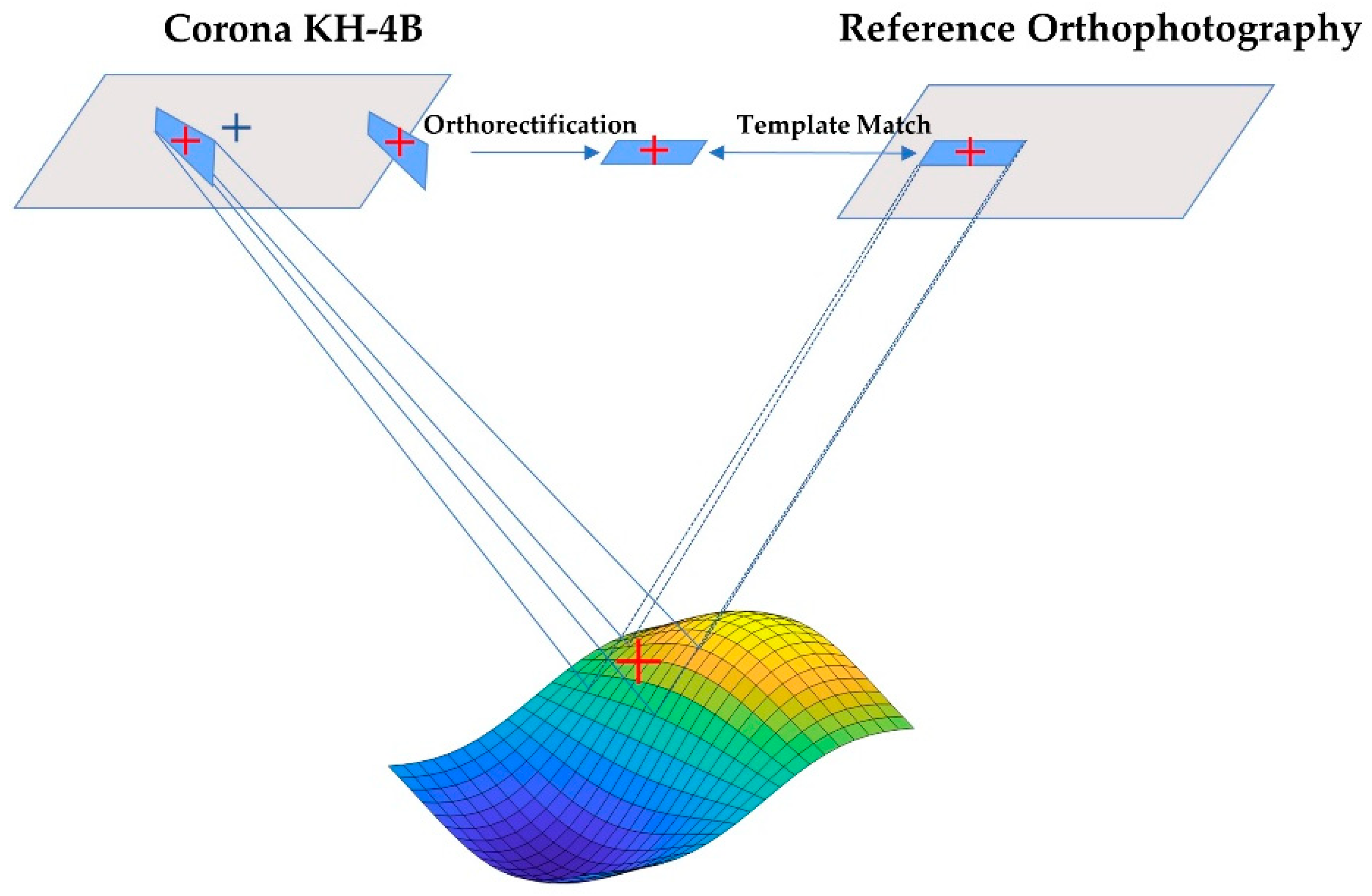
4.1.3. Feature Matching
We first perform pairwise matching using the nearest neighbor distance ratio [] (NNDR) for each level of the image pyramid to obtain initial matches. Then, the mismatches are removed using the Forward Selection and Consistency [] (FSC) method. Subsequently, the matches of all pyramid images are aggregated, and the FSC method is conducted on the fused match set. As a result, the final feature-matching results are obtained, and the transformation between the image pair is estimated.
4.2. Pyramid-Wise Template Matching
To further improve the matching performance, a pyramid-wise template matching strategy is applied. First, the reference image is resampled based on the estimated transformation matrix. Then, two image pyramids are constructed for the reference image and the KH-4B image, respectively. Finally, a template matching algorithm called CFOG [] is employed for precise matching at each layer of pyramid images. The detailed process is as follows.
- At the top level of the pyramid, the corner features of the KH-4B image gradient map are extracted using the GU-FAST algorithm.
- The corner points detected on the KH-4B image are mapped to the reference image based on the transformation matrix, and template matching is performed using the CFOG [].
- The matches are mapped to the next level of the image pyramid based on the resolution difference of different levels of the pyramid.
- The process 1–3 is repeated until the original resolution is reached.
4.3. Multi-Threshold Matching Enhancement
Local changes in the scene are an inevitable problem in matching multi-temporal remote sensing images, which can cause template matching to fall into local optima, producing erroneous matches. This significantly reduces the accuracy of control information and may even lead to failure in image orientation. Traditional match filtering methods struggle to eliminate these unreliable matches due to the following reasons: (1) The global reprojection error thresholds tend to be large due to the complex imaging model of KH-4B images, even when the matching points are completely correct. (2) Setting similarity thresholds becomes challenging due to non-linear radiometric distortions. (3) The panoramic camera model fails to converge when relatively low-accuracy generalized control points (16–32 m) from low-resolution layers in the image pyramid are used.
Aiming at eliminating the incorrect matches accurately, this study proposes a multi-threshold matching enhancement strategy (MTE) based on the scale and rotation change in a group of local feature points. Upon jointly considering a wide range of feature points, the unreliable points located in the change areas can be effectively removed, and more correct matches are found. The specific steps are as follows.
For a matching pair in the KH-4B image and in the reference image, we detect feature points with the FAST operator in a local area (~500 pixels) around , a group of feature points can be obtained. Considering the scale change and rotation between the KH-4B image and the reference image have been roughly eliminated, the offsets of the newly detected points and can be directly applied to to predict the corresponding points of the detected points on the reference images. Specifically, for a new feature point Pi, its initial corresponding point can be calculated as . After that, we use template matching to optimize the initial matching points and estimate a local transformation matrix using the refined matches. Based on the estimated transformation matrix, the scale change and rotation angle in the local area can be calculated. We set scale and rotation thresholds at 20% and 5°, respectively, based on the largest possible differences between KH-4B and reference imagery. If differences in scale and rotation are within these limits, we consider the local structures to be unchanged, and the new matches are retained; otherwise, the land cover has changed, and the new matches are discarded.
4.4. Model-Guided Matching
After obtaining sufficient relatively high-accuracy matches from the above matching process, we calculate the 14 parameters using the image model described in Section 3.2 and orthorectify the KH-4B image. Until now, notable geometric distortions caused by the intricate image process have been significantly reduced. We rematch the orthorectified image and the reference image to improve the accuracy. As shown in Figure 6, we first retain the previously obtained matching points in the reference image as feature points and discard the previous corresponding points on the KH-4B image. Second, we project the feature points to the KH-4B image with the calculated imaging parameters. Finally, we take the feature points as input and employ template matching on the reference image and coarsely orthorectified image to refine the matching results. The projected point on the KH-4B image in the second step and the adjusted feature point on the reference image in the last step are taken as a pair of generalized control points.

Figure 6.
Model-guided image matching. First, translate the reference image’s feature points to the panoramic image. Then, reapply the template matching between the orthorectified local KH image block and the reference image. Finally, utilize these matching results as generalized control points.
5. Experiments and Results
To thoroughly evaluate the accuracy and generalization of 2OC, KH-4B images (listed in Table 4) from different locations with diverse terrain features and complex distortions were used as validation data. The evaluation was conducted by quantifying the accuracy of orientation and orthorectification.

Table 4.
The details of multi-region Corona images and reference images.
5.1. The Accuracy of Orientation
We first assess the accuracy of image orientation, which was evaluated using residual orientation and pose parameters. All obtained correspondences between the KH image and the reference orthophoto are used as generalized control points. The calculation of root mean square error (RMSE) of generalized control points is as follows:
where is the image coordinate of the generalized control point, are the image coordinates calculated using the panoramic camera model, is the number of generalized control points, and is the RMSE of residual. In Figure 7, the generalized control points required for DS1101-1069DF090b image orientation are depicted and extracted using the 2OC method.

Figure 7.
The matches, namely the generalized control points, between the DS1101-1069DF090b image (c) and the reference Google orthophoto image (d), and the green dots indicate the control points, and the red numbers indicate the point numbers. (a,b,e,f) are the corresponding zoomed-in areas in (c,d).
Figure 7 shows the generalized control points required for DS1101-1069DF090b image orientation, extracted using 2OC. Overall, the 2OC approach demonstrates advantages in terms of both generalized control point quantity and distribution that manual extraction methods cannot achieve. In the zoomed-in view, the precision of these generalized control points has reached a level comparable to human recognition accuracy. The experimental results in Table 5 indicate that: (1) The overall accuracy is better than 2 pixels, with significantly higher accuracy in the central image blocks compared to the edge image blocks. This may be attributed to severe panoramic distortion and image deformation at the edges. (2) Model-guided matching effectively reduces the impact of panoramic distortion on the accuracy of control information, improving the orientation accuracy by 30% to 45%. For comparison with state-of-the-art work [], we conducted experiments on the DS1117-2071DF008 dataset. The results show that the generalized control points extracted by 2OC outperform [] in terms of quantity and distribution. The orientation accuracies are as follows: a (1.54), b (1.17), c (1.3), d (1.56), which are better than 1.94 of [].

Table 5.
The RMSE of orientation.
Furthermore, to verify the generalization capability, we applied 2OC to the KH-4B images in Table 5 and presented the orthorectified images and mean errors of orientation in Figure 8. The overall accuracy is better than 2 pixels. The Gansu Province, known for its Loess Plateau, exhibits characteristics of weak texture, repetitive patterns, and significant speckle noise. Beijing and Vermont, USA, represent cases with land cover changes and radiometric distortions. The snow-covered region in Tibet leads to overexposure and severe non-linear radiometric distortion. The KH-4B images in Burkina Faso exhibit considerable noise due to camera and terrain factors. The area near the Ob River in Russia has numerous small lakes, where frozen water bodies in the KH-4B images are overexposed. In contrast, the water bodies in the reference image are underexposed, resulting in severe radiometric distortion. Moreover, changes in the lake edges over a 50-year period are observed. Figure 9 provides a detailed demonstration of complex distortions, including non-linear radiometric distortion, land cover changes, image noise, weak texture, cloud cover, and repetitive patterns. These results demonstrate that 2OC exhibits high generalization capability and can handle KH-4B images with various terrain types and complex distortions.

Figure 8.
The orientation accuracy in various areas. The red font in the yellow square represents the orientation mean square error of each panoramic image. (a) The orthophoto of Russia; (b) The orthophoto of Gansu, China; (c) The orthophoto of Beijing, China; (d) The orthophoto of Vermont, USA; (e) The partial map of Russia; (f) The partial map of USA; (g) The world map; (h) The China Map; (i) The orthophoto of Chongqing, China; (j) The orthophoto of Arizona, USA; (k) The Burkina Faso map; (l) The Ethiopia map; (m) The orthophoto of Burkina Faso; (n) The orthophoto of Ethiopia; (o) The orthophoto of the Qinghai–Tibet Plateau.

Figure 9.
The registration checkboard of the KH-4B orthophoto and reference image with complex image contents, where the image with a red dot is the KH-4B Orthophoto. (a–c) are located at the Qinghai–Tibet Plateau, and Beijing, China, with large NID; (d,e) are located in America and Beijing with land cover change; (f,h) are both located in Burkina Faso with noises; (g) is located in Gansu province, China with few textures; (i) is located in Ethiopia with large cloud coverage; (j) is located in Chongqing, China with repetitive textures.
Table 6 shows detailed attitude parameters for the DS1101-1069DF090 dataset. The attitude parameters between sub-images vary due to different primary point coordinates but should follow certain patterns. Here, X represents the east–west direction, Y represents the north–south direction, and Z represents the plumb line direction. The true scan time for a panoramic image is approximately 0.36 s (84,000 pixels), so the scan time for sub-images is approximately 0.154 s (36,000 pixels)/0.103 s (24,000 pixels). However, in this experiment, the scan time for sub-images is normalized to 1. Therefore, Ys1 should be around ~1.2 /0.8 (equivalent to approximately 77.7 for a true panoramic camera), with an orbital altitude of around 170 km. represents the rotation around the Y-axis, which represents the camera’s scanning angle. represents the rotation around the X-axis and should be around −15 degrees. However, the experimental results show variations between −10° and −20°. This may be due to the satellite’s attitude not strictly aligning with the plumb line on the ground, resulting in a deviation in the scanning direction of the camera. represents the rotation around the Z-axis (plumb line direction), and from the distribution of generalized control points in Figure 7d of the Google image, a deviation of approximately 10° can be observed. The P (vertical height difference) for a and d is larger than that of b and c, which may be attributed to more severe image deformation at the ends.

Table 6.
The 14 parameters of the four sub-images of DS1101-1069DF090.
5.2. The Accuracy of Orthorectification
In this section, we present the registration checkerboard image between DS1101-1069DF092c and the reference image, as shown in Figure 10, and test the accuracy of the orthophoto generated using the proposed model. Orthorectified images are closely related to attitude parameters, and their accuracy reflects the accuracy of the attitude parameters. For a comprehensive evaluation, two metrics, the mosaic error and the error of the generalized control points, are applied. Specifically, we evaluate the mosaic accuracy based on three aspects: standard deviation (SD), maximum value (Max), and mean value (Mean) of the differences between the coordinate match points located in the overlapping regions of adjacent sub-image blocks. Table 7 provides detailed information accounting for the mosaic accuracy between the orthorectified image blocks of DS1101-1069DF089 and DS1101-1069DF090.

Figure 10.
The registration results of the KH-4B image, DS1101-1069DF092c, and the reference image. (a–c) show the zoomed-in registration results of unchanged mountains; (d) shows the zoomed-in registration result of changed rivers. (e) The registration checkboard of the KH-4B orthophoto and reference image. (f) shows the zoomed-in registration result of the changed mountains area. (g,h) show the zoomed-in registration results of the changed plain area, where rivers have transformed into farmland and roads have undergone alterations. (i) shows the zoomed-in registration result of partially unchanged mountainous regions where rivers have experienced minor changes.

Table 7.
The detailed mosaic error of DS1101-1069DF089 and DS1101-1069DF090.
According to Table 7, the mosaic errors in the orthorectified images are mostly within 1 pixel, with the maximum value ranging from 1 to 4 pixels and the average value being better than 1 pixel. The mosaic errors at the edges of the image blocks are larger than those in the middle, which is consistent with the image orientation accuracy. This indicates that the proposed 14-parameter panoramic camera model accurately reverts the panoramic imaging process and can be used for orthorectification.
To obtain accurate ground checkpoints, sub-images were first stitched into a complete orthorectified image using the recovered georeferenced information. Then, 43 ground checkpoints were manually selected. Figure 11 shows the detailed distribution of these checkpoints. The root mean square error (RMSE) of the ground checkpoints in the X-direction is 3.89 m, and in the Y-direction is 3.29 m. The average RMSE in the X-direction is 2.69 m, and in the Y-direction is 2.52 m.

Figure 11.
The orthophoto of DS1101-1069DF089, along with 42 checkpoints marked with red-cross dots.
6. Discussion
This section provides a detailed discussion of three critical steps in 2OC that may significantly affect the orientation and orthorectification accuracy, which are the PG stripe correction accuracy, the stability of the feature matching algorithm (NIFT), and the robustness of multi-threshold matching enhancement (MTE) to resist complex distortions.
6.1. The Impact of PG Stripe Correction on Orientation Accuracy
As described in Section 3.2, estimating rotation and translation components using the overlapping regions between adjacent image blocks may be affected by local image deformations, leading to stitching errors and a decrease in orientation accuracy. To simultaneously avoid stitching errors and scanning errors, this study adopts a method of processing individual image blocks before stitching. This is because the rotation and translation components of the image blocks are compensated for in the attitude parameters, including the angular and linear elements.
As shown in Table 8, the improvement in accuracy due to PG stripe correction for compensating image distortion is not as significant as []. Therefore, we constructed the PG stripe curves for each sub-image and found that this is mainly because the PG stripe curves of the sub-images are almost linear (as shown in Figure 12, Figure 13 and Figure 14), similar to image rotation. Hence, they can be compensated for using the angular elements of the attitude parameters. However, in the stitched complete image (with rotation and translation), as depicted in Figure 15, the PG stripe becomes more intricate. This complexity is likely due to the estimation bias in the rotation component. Consequently, PG stripe correction proves to be significant for the approach that involves image stitching followed by correction [].

Table 8.
The orientation accuracy for the four sub-images of DS1101-1069DF089 with/without film deformation adjustment based on PG stripe.

Figure 12.
The PG stripe curves of the four sub-images, a, b, c, d, of DS1101-1069DF089.

Figure 13.
The PG stripe curves of the four sub-images, a, b, c, d, of DS1101-1069DF090.

Figure 14.
The PG stripe curves of sub-images, a, b, c, d, of DS1105-1071DF141.
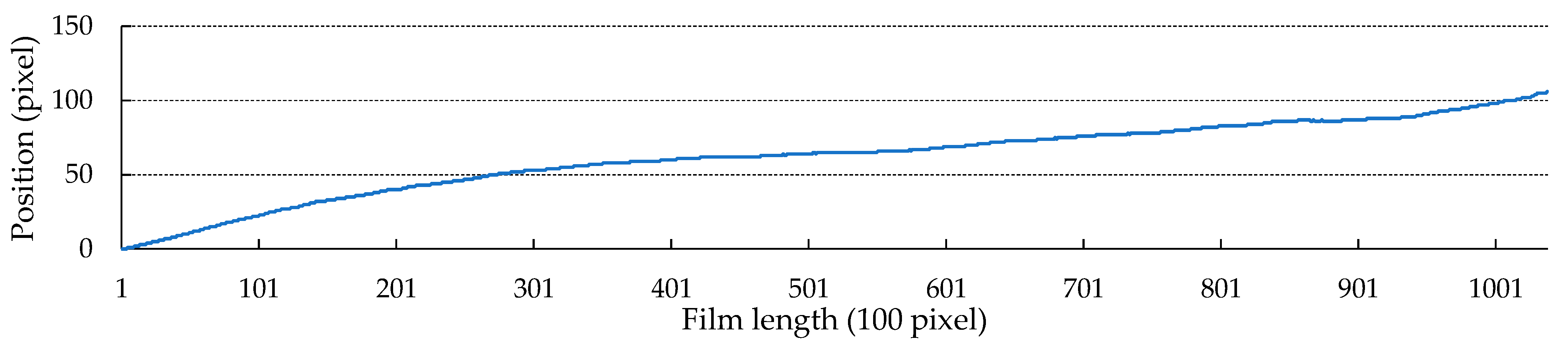
Figure 15.
The PG stripe curve of the stitched panoramic image DS1105-1071DF141.
6.2. The Evaluation of NIFT
To evaluate the performance of NIFT, we created a dataset consisting of 30 pairs of down-sampled KH-4B images and reference images (as shown in Table 9) and compared it with SIFT [], LNIFT [], and RIFT []. For the comparative methods, the default parameters provided by the authors are used. For NIFT, the scale factor, orientation factor, descriptor orientation, and the number of concentric circles were set to {4, 6, 12, 3}, respectively. Accuracy rate (SR) and the number of correct matching points (NCM) were used as evaluation metrics. SR can be calculated as follows:
where is the number of successfully matched image pairs, is the total number of image pairs involved, and SR represents the robustness of the matching algorithm.

Table 9.
The details of the dataset used in feature matching.
Table 10 gives the detailed matching results for the four algorithms. Among them, SIFT, as a classical method, only achieved a correctness rate of 6.6%. LNIFT algorithm obtained a higher number of NCM with 108. However, its SR was only 3.3%. RIFT had the same NCM as LNIFT but achieved higher robustness, with an SR of 53%. In comparison, NIFT successfully matched all image pairs and achieved more than three times NCM compared with the other algorithms.

Table 10.
The compared matching results.
To further evaluate the robustness of NIFT against rotation, we selected two representative images from Dataset 3 and manually rotated the images in steps of 5° within the range of [0, 360], creating 73 pairs of images with different rotation distortions. The matching results in Figure 16 demonstrate that although the NCM fluctuates to some extent due to the multi-directional filtering features, the algorithm is still able to obtain more than 190 correct matching points at any angle.

Figure 16.
The NCM curve of NIFT under various rotational distortions.
6.3. The Evaluation of MTE
To evaluate the effectiveness of the multi-threshold matching enhancement strategy (MTE), we designed a series of experiments. To be simple, the 2OC without any matching enhancement strategy is referred to as ; the 2OC using the strategy of eliminating incorrect points based on reprojection error is referred to as , where the reprojection error threshold is adaptively adjusted using three times the mean error; the 2OC enhanced with MTE is referred to as . All three methods were applied to the same image dataset, which consists of DS1101-1069DF090 Corona image, Google Earth orthophoto, and 30 m STRM DEM data of the same area.
The experimental results in Table 11 show that there is no significant difference between the three methods in pairs a and b of image blocks, with an accuracy difference of less than 1 pixel. This is because the a and b regions are mountainous areas with little variation in land features and only a few low-quality generalized control points. In Region C, and achieved an accuracy of 3–4 pixels, while had an error of only 1.3 pixels. This is mainly due to the presence of two rivers with significant changes in Region C, resulting in a number of low-quality generalized control points and a large number of matching errors in image orientation. In Region D, where land feature changes are the most pronounced and low-quality generalized control points dominate, both and failed, while achieved an error of 1.4 pixels. This indicates that: (1) Complex distortions in the images indeed generate a large number of low-reliability match points, severely affecting the accuracy of image orientation and even preventing proper convergence. (2) The multi-threshold matching enhancement strategy effectively reduces the proportion of low-quality match points in the overall set of match points by eliminating low-reliability match points and increasing high-reliability match points, resulting in the correct convergence of the panoramic camera model estimation.

Table 11.
The RMSE of orientation for DS101-1069DF90 of three methods. a, b, c, and d represent the sub-image of DS101-1069DF90.
7. Conclusions
This study presents a method for orientation and rectification of Corona KH-4B images (referred to as 2OC). First, to eliminate the focal length and panoramic distortion in KH-4B images, a panoramic mathematical model with 14 parameters and a time-iterative orthorectification method are proposed. Second, to counter complex distortions (radiometric/geometric distortions, weak texture, land changes, etc.) and automatically extract control information, a robust generalized control information extraction algorithm is proposed. Specifically, this includes the Maximum Sector Norm-based Primary Direction Estimation (NIFT), the Multi-Threshold Matching Enhancement Strategy (MTE) based on local texture, scale, and orientation, and the Model-Guided Matching.
Next, the generalization of 2OC is validated using KH-4B images with diverse terrain features (plateaus, glaciers, plains, hills, basins, etc.) and complex distortions from different locations worldwide (USA, Russia, Ethiopia, Burkina Faso, China) (Table 5). The results demonstrate superior orientation accuracy of better than 2 pixels, orthorectification accuracy of approximately 1 pixel, and planimetric accuracy of better than 4 m. Furthermore, detailed ablation and comparative experiments are conducted on the proposed NIFT, MTE, and Model-Guided Matching modules, highlighting their significant contributions to the generalization of 2OC. For example, allowing temporal differences (50 years) between the reference image and KH-4B image, non-linear radiometric distortion, rotational distortion ([0, 360)), scale distortion (1:4), and local land changes. Additionally, the rationality of separately processing sub-images and the impact of PG stripe correction are analyzed in detail.
Finally, the application of 2OC is not limited to handling Corona KH-4B images. By replacing the image mathematical model, it can be applied to a wider range of historical remote sensing images with complex multi-source and multi-temporal differences. In future studies, we will (1) attempt to use the rational function model commonly used in the remote sensing field to rectify KH-4B images for handling other historical remote sensing images with significant temporal differences and (2) explore the combination of manual features and deep learning features to extract control information more rapidly.
Author Contributions
Conceptualization, Z.H., Y.L. and L.Z.; methodology, Z.H., Y.L. and L.Z; validation, Z.H., Y.L. and L.Z.; formal analysis, Z.H. and Y.S.; investigation, X.H. and Z.H.; data curation, Z.H., H.A. and Y.S.; writing—original draft preparation, Z.H. and Y.L.; writing—review and editing, Z.H., Y.L., C.Z. and L.Z.; supervision, Y.L. and L.Z.; project administration, Y.L.; funding acquisition, Y.L. All authors have read and agreed to the published version of the manuscript.
Funding
This research was funded by the Basic scientific research project of the Chinese Academy of Surveying and Mapping (CASM), grant number AR2305.
Data Availability Statement
Not applicable.
Conflicts of Interest
The authors declare no conflict of interest.
References
- Dashora, A.; Lohani, B.; Malik, J.N. A repository of earth resource information—CORONA satellite programme. Curr. Sci. 2007, 92, 926–932. [Google Scholar]
- Madden, F. The CORONA camera system-iteks contribution to world security. J. Br. Interplanet. Soc. 1999, 52, 379–396. [Google Scholar]
- Cloud, J. Imaging the World in a Barrel: CORONA and the Clandestine Convergence of the Earth Sciences. Soc. Stud. Sci. 2001, 31, 231–251. [Google Scholar] [CrossRef]
- Ur, J. CORONA satellite photography and ancient road networks: A northern Mesopotamian case study. Antiquity 2003, 77, 102–115. [Google Scholar] [CrossRef]
- Casana, J. Global-Scale Archaeological Prospection using CORONA Satellite Imagery: Automated, Crowd-Sourced, and Expert-led Approaches. J. Field Archaeol. 2020, 45, S89–S100. [Google Scholar] [CrossRef]
- Philip, G.; Donoghue, D.; Beck, A.; Galiatsatos, N. CORONA satellite photography: An archaeological application from the Middle East. Antiquity 2002, 76, 109–118. [Google Scholar] [CrossRef]
- Watanabe, N.; Nakamura, S.; Liu, B.; Wang, N. Utilization of Structure from Motion for processing CORONA satellite images: Application to mapping and interpretation of archaeological features in Liangzhu Culture, China. Archaeol. Res. Asia 2017, 11, 38–50. [Google Scholar] [CrossRef]
- Rizayeva, A.; Nita, M.D.; Radeloff, V.C. Large-area, 1964 land cover classifications of Corona spy satellite imagery for the Caucasus Mountains. Remote Sens. Environ. 2023, 284, 113343. [Google Scholar] [CrossRef]
- Narama, C.; Shimamura, Y.; Nakayama, D.; Abdrakhmatov, K. Recent changes of glacier coverage in the western Terskey-Alatoo range, Kyrgyz Republic, using Corona and Landsat. Ann. Glaciol. 2006, 43, 223–229. [Google Scholar] [CrossRef]
- Andersen, G.L. How to detect desert trees using corona images: Discovering historical ecological data. J. Arid Environ. 2006, 65, 491–511. [Google Scholar] [CrossRef]
- Narama, C.; Kääb, A.; Duishonakunov, M.; Abdrakhmatov, K. Spatial variability of recent glacier area changes in the Tien Shan Mountains, Central Asia, using Corona (~1970), Landsat (~2000), and ALOS (~2007) satellite data. Glob. Planet. Change 2010, 71, 42–54. [Google Scholar] [CrossRef]
- Altmaier, A.; Kany, C. Digital surface model generation from CORONA satellite images. ISPRS J. Photogramm. Remote Sens. 2002, 56, 221–235. [Google Scholar] [CrossRef]
- Jacobsen, K. Calibration and Validation of Corona kh-4b to Generate Height Models and Orthoimages. ISPRS Ann. Photogramm. Remote Sens. Spat. Inf. Sci. 2020, 2020, 151–155. [Google Scholar] [CrossRef]
- Lauer, B. Exploiting Space-Based Optical and Radar Imagery to Measure and Model Tectonic Deformation in Continental Areas. Ph.D. Thesis, Université Paris Cité, Paris, France, 2019. [Google Scholar]
- Sohn, H.G.; Kim, G.-H.; Yom, J.-H. Mathematical modelling of historical reconnaissance CORONA KH-4B Imagery. Photogramm. Rec. 2004, 19, 51–66. [Google Scholar] [CrossRef]
- Dashora, A.; Sreenivas, B.; Lohani, B.; Malik, J.N.; Shah, A.A. GCP collection for corona satellite photographs: Issues and methodology. J. Indian Soc. Remote Sens. 2006, 34, 153–160. [Google Scholar] [CrossRef]
- Lowe, D.G. Distinctive image features from scale-invariant keypoints. Int. J. Comput. Vis. 2004, 60, 91–110. [Google Scholar] [CrossRef]
- Bay, H.; Ess, A.; Tuytelaars, T.; Van Gool, L. Speeded-Up Robust Features (SURF). Comput. Vis. Image Underst. 2008, 110, 346–359. [Google Scholar] [CrossRef]
- Sedaghat, A.; Mokhtarzade, M.; Ebadi, H. Uniform Robust Scale-Invariant Feature Matching for Optical Remote Sensing Images. Ieee Trans. Geosci. Remote Sens. 2011, 49, 4516–4527. [Google Scholar] [CrossRef]
- Bhattacharya, A.; Bolch, T.; Mukherjee, K.; King, O.; Menounos, B.; Kapitsa, V.; Neckel, N.; Yang, W.; Yao, T. High Mountain Asian glacier response to climate revealed by multi-temporal satellite observations since the 1960s. Nat. Commun. 2021, 12, 4133. [Google Scholar] [CrossRef]
- Casana, J.; Cothren, J. Stereo analysis, DEM extraction and orthorectification of CORONA satellite imagery: Archaeological applications from the Near East. Antiquity 2008, 82, 732–749. [Google Scholar] [CrossRef]
- Nita, M.D.; Munteanu, C.; Gutman, G.; Abrudan, I.V.; Radeloff, V.C. Widespread forest cutting in the aftermath of World War II captured by broad-scale historical Corona spy satellite photography. Remote Sens. Environ. 2018, 204, 322–332. [Google Scholar] [CrossRef]
- Shin, S.W.; Schenk, T. Rigorous Modeling of the First Generation of the Reconnaissance Satellite Imagery. J. Remote Sens. 2008, 24, 223–233. [Google Scholar]
- Ye, Y.; Shan, J.; Bruzzone, L.; Shen, L. Robust Registration of Multimodal Remote Sensing Images Based on Structural Similarity. IEEE Trans. Geosci. Remote Sens. 2017, 55, 2941–2958. [Google Scholar] [CrossRef]
- Ye, Y.X.; Bruzzone, L.; Shan, J.; Bovolo, F.; Zhu, Q. Fast and Robust Matching for Multimodal Remote Sensing Image Registration. IEEE Trans. Geosci. Remote Sens. 2019, 57, 9059–9070. [Google Scholar] [CrossRef]
- Li, J.; Hu, Q.; Ai, M. RIFT: Multi-Modal Image Matching Based on Radiation-Variation Insensitive Feature Transform. IEEE Trans. Image Process. 2020, 29, 3296–3310. [Google Scholar] [CrossRef] [PubMed]
- Li, J.; Xu, W.; Shi, P.; Zhang, Y.; Hu, Q. LNIFT: Locally Normalized Image for Rotation Invariant Multimodal Feature Matching. IEEE Trans. Geosci. Remote Sens. 2022, 60, 1–14. [Google Scholar] [CrossRef]
- Ghuffar, S.; Bolch, T.; Rupnik, E.; Bhattacharya, A. A Pipeline for Automated Processing of Declassified Corona KH-4 (1962–1972) Stereo Imagery. IEEE Trans. Geosci. Remote Sens. 2022, 60, 1–14. [Google Scholar] [CrossRef]
- Sarlin, P.-E.; DeTone, D.; Malisiewicz, T.; Rabinovich, A. Superglue: Learning feature matching with graph neural networks. In Proceedings of the IEEE/CVF Conference on Computer Vision and Pattern Recognition, New Orleans, LA, USA, 21–24 June 2020; pp. 4938–4947. [Google Scholar]
- Woolsey, R.J. CORONA and the Intelligence Community. Stud. Intell. 1996, 39, 14. [Google Scholar]
- Kanopoulos, N.; Vasanthavada, N.; Baker, R.L. Design of an image edge detection filter using the Sobel operator. IEEE J. Solid-State Circuits 1988, 23, 358–367. [Google Scholar] [CrossRef]
- Harris, C.G.; Stephens, M.J. A Combined Corner and Edge Detector. In Proceedings of the Alvey Vision Conference, Manchester, UK, 31 August–2 September 1988. [Google Scholar]
- Leutenegger, S.; Chli, M.; Siegwart, R.Y. BRISK: Binary Robust invariant scalable keypoints. In Proceedings of the 2011 International Conference on Computer Vision, Barcelona, Spain, 6–13 November 2011; pp. 2548–2555. [Google Scholar]
- Wu, Y.; Ma, W.; Gong, M.; Su, L.; Jiao, L. A Novel Point-Matching Algorithm Based on Fast Sample Consensus for Image Registration. IEEE Geosci. Remote Sens. Lett. 2015, 12, 43–47. [Google Scholar] [CrossRef]
Disclaimer/Publisher’s Note: The statements, opinions and data contained in all publications are solely those of the individual author(s) and contributor(s) and not of MDPI and/or the editor(s). MDPI and/or the editor(s) disclaim responsibility for any injury to people or property resulting from any ideas, methods, instructions or products referred to in the content. |
© 2023 by the authors. Licensee MDPI, Basel, Switzerland. This article is an open access article distributed under the terms and conditions of the Creative Commons Attribution (CC BY) license (https://creativecommons.org/licenses/by/4.0/).