Article

An In-Vehicle Smartphone RTK/DR Positioning Method Combined with OSM Road Network

School of Transportation, Southeast University, Nanjing 211189, China
*
Author to whom correspondence should be addressed.
Remote Sens. 2023, 15(2), 398; https://doi.org/10.3390/rs15020398
Submission received: 13 November 2022 / Revised: 29 December 2022 / Accepted: 6 January 2023 / Published: 9 January 2023
(This article belongs to the Special Issue Remote Sensing in Urban Positioning and Navigation)

Abstract

:
In vehicle navigation scenarios, the RTK positioning results of smartphones are prone to jumps due to the interference of complex urban environments, and the heading angle of dead reckoning (DR) is prone to divergence. In order to obtain more stable and high-precision smartphone positioning results, this paper proposes an RTK/DR positioning method combined with the OpenStreetMap road network. The OpenStreetMap road network data are used to correct the heading angle during the linear motion phase to improve heading angle accuracy. In order to reduce the impact of RTK results jumping on subsequent DR, it is possible to set up a measurement update switch, which combines the RTK covariance matrix, vehicle motion state, and RTK heading angle change information to determine whether to perform a measurement update. The research uses two smartphones to carry out four vehicle positioning tests. The eight sets of test results show that the heading angle correction method based on the OpenStreetMap road network can effectively control the accumulation of heading angle errors and allow DR trajectory to be more consistent with the benchmark. Compared with RTK, the forward accuracy of RTK/DR positioning method is almost unchanged, even though the direction accuracy and lateral positioning accuracy are significantly improved. The RTK/DR horizontal positioning accuracy of both smartphones is approximately 1.3 m, which is better rather than the RTK results. The proposed RTK/DR positioning method can obtain more reliable orientation and position information than RTK.

1. Introduction

Vehicle navigation is an indispensable item in the rapid development of intelligent transportation and intelligent vehicles related to practical needs, such as fast wayfinding, avoiding traffic congestion, and improving traffic operation rate [1]. Following the widespread use of hardware sensors in intelligent vehicle systems, the method of vehicle positioning has also expanded from single GNSS (global navigation satellite systems) positioning to fusion positioning using GNSS receivers, inertial navigation systems [2], LIDAR (light detection and ranging) devices [3], and odometers [4,5]. For most drivers, smartphones, as indispensable devices for travel, perform the task of vehicle navigation in most driving environments.
Currently, some smartphone GNSS receivers can output pseudorange, Doppler, carrier phase, and other satellite observation data in real time at 1 Hz frequency. At the same time, the smartphone can receive observation data broadcast by the reference station through the network. By differencing the decoded reference station observation data and satellite observation data, RTK positioning of the smartphone can be achieved [6,7,8]. At present, the RTK positioning of smartphones has been used in some models and can play a stable role in an open-air environment. However, in the complex urban canyon environment, the interference of errors, such as multipath and non-line-of-sight [9,10] make it challenging to guarantee smartphone positioning accuracy and stability. The inertial sensor integrated inside the smartphone provides the possibility for dead reckoning (DR) [11,12,13,14]. In practical applications, the low-cost inertial navigation equipment has relatively high data noise and the short-time integral operation introduces significant errors in velocity, attitude, and position [15,16]. Therefore, the RTK/DR method result will change with the RTK result, and it is not easy to effectively improve the positioning accuracy. Therefore, improving DR accuracy becomes the critical point in order to solve the problem.
Velocity and heading angle are the main factors affecting DR. Since the accelerometer noise of the smartphone is relatively large, the velocity obtained by RTK calculation is more reliable than updating velocity through the acceleration integral. Similarly, the heading angle error accumulates through the angular velocity, and acceleration integral update is fast, in addition to being needed to correct the heading angle in real time. The correction of the heading angle is generally based on the information of vehicle motion state and road environment. There is a range of available methods, e.g., zero velocity correction [17], road line constraints [18], straight line detection [19], and map matching [20]. Considering the in-vehicle navigation of smartphones, positioning is often used in conjunction with maps so that it is more practical to correct the heading angle through the road direction. According to the reference [21], the currently available open-source OSM (OpenStreetMap) road network data have an overall directional similarity of 95% and an accuracy level sufficient to correct the heading angle. Therefore, this paper proposes a method for computing the heading angle using the OSM road direction and designs a point-to-line map matching scheme, which combines the vehicle motion state and the change of the DR heading angle to select an appropriate timing for correction.
Smartphone RTK uses a robust Kalman filter to adapt to complex urban environments. RTK/DR uses a combination method and estimates velocity and position based on the standard Kalman filter. After heading angle correction, DR has high directional accuracy. However, when RTK seriously jumps, the error affecting RTK/DR combination will cause the overall offset of subsequent DR. In order to solve this problem, it is possible to set up a measurement update switch in the combination filter: according to the covariance matrix Pk calculated by RTK, vehicle motion state and RTK positioning heading angle change information, and it is possible to determine whether it is necessary to perform a measurement update.

2. Materials and Methods

This section introduces RTK robust Kalman filter solution, DR, heading angle correction method, and RTK/DR positioning method based on the Kalman filter.

2.1. Smartphone RTK Model

This work researches mainly the RTK positioning model under the short baseline, which means that the distance between the smartphone and the reference station is generally within 10 km. The smartphone connects to the reference station through the network and decodes the observation data of the reference station itself in real time. Firstly, the raw smartphone and reference station observations are matched. Then, the inter-satellite and inter-station differences are computed in order to obtain the pseudorange double difference equation and the carrier phase double difference equation. Additionally, the velocity is measured using Doppler observations from smartphones. Finally, the Doppler inter-satellite single difference equation, pseudorange double difference equation, and carrier phase double difference equation are combined to obtain the observation equation of the Kalman filter [22]. The observation equation is as follows:
L = H X + V
where
X = [ x y z v x v y v z a x a y a z N ˜ 1 N ˜ 2 ]
H = [ l 1 m 1 w 1 0 0 l 1 m 1 w 1 1 0 l v 1 m 1 0 0 0 l n m n w n 0 0 l n m n w n 0 1 l v n m n 0 0 0 ]
m i = l i d t
w i = 1 2 l i d t 2
In the above formula, L represents the observations of pseudorange double difference, carrier phase double difference, and Doppler single difference. X represents the parameter to be estimated, including position, velocity, acceleration, and double difference ambiguity. l i represents the direction cosine of the satellite. l v i represents the satellite velocity cosine.
Smartphones generally use low-cost GNSS receivers, which lack modules for anti-jamming. In order to adapt to the complex urban environment, this work uses a robust Kalman filter that accomplishes parameter estimation. During dynamic positioning, there are many cycle slips in the carrier phase data of the smartphone, and it is difficult to fix the ambiguity, so the ambiguity parameter in the model is a floating-point solution. The robust Kalman filter scheme used in this work is as follows [23]:
R ¯ i = R i / α
α i = { 1 | v ˜ i | k 0 k 0 | v ˜ i | ( k 1 | v ˜ i | k 1 k 0 ) 2 k 0 < | v ˜ i | k 1 10 8 | v ˜ i | > k 1
v ˜ i = v i v ¯ σ v
In the above formula, R ¯ i represents the equivalent variance; R i represents the variance of the highest residual v i corresponding to the observed value; α i represents the variance amplification factor; v ˜ i represents the standardised residual; and k 0 and k 1 represent the thresholds: in this work, k 0 = 1.2 and k 1 = 3.0 . Every epoch is solved by a robust iteration. When α i is equal to 10−8, the corresponding observations are removed, and the iteration is carried out until no observation is removed.
The RTK positioning model designed in this work does not limit the number of constellations and satellites. All valid satellite data received by the smartphone participate in the positioning process, and the constellations used include GPS, BD, Galileo, and GLONASS. Other conventional optimisation methods are also used in smartphone RTK, e.g., gross error detection between epochs of satellite observations, smoothing pseudorange with Doppler data, and selection of reference satellites according to elevation mask and carrier-to-noise ratio information.

2.2. Smartphone DR Model

Dead reckoning (DR) is a relative positioning technology. Its basic principle is to calculate the attitude, velocity, and position of the vehicle in the next time, according to the information collected by the sensor after initialising the attitude, velocity, and position of the starting point. DR includes four processes: starting point initialisation, attitude update, velocity update, and position update. The attitude update frequency is the same as the IMU (inertial measurement unit) sampling frequency, while the velocity and position update frequency is the same as the RTK positioning frequency.
The first step is to initialise the starting point. This work uses the dynamic alignment method to initialise the smartphone’s attitude, velocity, and position. The absolute value of the forward acceleration of the smartphone is generally lower than 0.01 m/s2 when it is stationary. When the forward acceleration is higher than 0.5 m/s2, the vehicle can be considered as not stationary. When the forward acceleration is higher than 0.5 m/s2 and the horizontal distance between adjacent RTK results is higher than 2 m, the initialisation process of the starting point is triggered. The specific formula is as follows:
{ P O S D R = P O S R T K v n D R = v n R T K v e D R = v e R T K v u D R = 0 t x = cos ( B k 1 R T K ) sin ( B k R T K ) sin ( B k 1 R T K ) cos ( B k R T K ) cos ( L k R T K L k 1 R T K ) t y = sin ( L k R T K L k 1 R T K ) cos ( B k R T K ) ψ D R = ψ R T K = arctan ( t y t x )
In the above formula, P O S represents the latitude, precision, and geodetic height; v n , v e , and v u represent the velocity in the E, N, and U directions, respectively; t x and t y represent the temporary variables; k represents RTK positioning epoch number; and ψ represents the heading angle.
Smartphones can directly output attitude quaternions. By converting the raw attitude quaternion into Euler angles, it is possible to find that the heading angle has a systematic deviation from the actual value, due to the disturbance of the vehicle magnetic field. Therefore, ψ D R was used to replace the raw heading angle during the initialisation phase. The roll and pitch angles are directly output by using the smartphone. Finally, the new Euler angles are converted into quaternions.
The second step is attitude update. The attitude update was carried out through the Mahony complementary filter algorithm, which uses the cross product of acceleration and gravity to compensate for gyroscope data. In the carrier phase coordinate system (b coordinate system), the acceleration of the smartphone is normalised to obtain:
a b , n o r m = 1 | a b | [ a x a y a z ]
When the carrier phase is at rest, the normalised gravity of the navigation coordinate system (n coordinate system) is g n = [ 0 0 1 ] T , which is transformed into the carrier phase coordinate system:
g b = ( C b n ) g n = [ 2 ( q 1 q 3 q 0 q 2 ) 2 ( q 2 q 3 + q 0 q 1 ) q 0 2 q 1 2 q 2 2 + q 3 2 ]
The cross product of a b , n o r m and g b is the error correction amount of the gyroscope:
e a c c = a b , n o r m × g b
Finally, the PI controller is used to compensate for the angular velocity:
g y r o = g y r o + k s e a c c + k i e a c c
In the above formula, g y r o represents the angular velocity in the carrier coordinate system; k s = 1 and k i = 0.001 .
The compensated angular velocity was used to update the attitude quaternion and convert the updated attitude quaternion into Euler angles in order to accomplish the attitude update process.
The third step is velocity update. There are two ways to measure the velocity of smartphones, i.e., acceleration integration and the Doppler velocimetry. Figure 1 shows the velocity obtained using the two methods. The blue line represents the velocity obtained through acceleration integration. The orange line represents the velocity obtained through Doppler velocimetry, and the red line represents the actual velocity. It can be found that because the accelerometer noise of smartphones is significant, the velocity and actual value of the integral acceleration calculation are high. The velocity measured using Doppler data is more consistent with the actual value. Therefore, the Doppler velocimetry is used to update the velocity.
The Doppler velocity measurement is related to RTK positioning results, and the direction of velocity is inconsistent with the RTK positioning heading angle, so DR velocity cannot be directly assigned. In the actual positioning process, RTK velocity is measured in the WGS84 coordinate system. Firstly, it is converted to the ENU (East, North, Up) coordinate system in order to calculate horizontal velocity. Then, the horizontal velocity is projected to the DR heading angle direction and decomposed into the N and E directions. In DR, only the horizontal position is focused, so the geodetic height is not updated, and the RTK geodetic height is directly assigned to DR. The velocity update formula is as follows:
{ v n D R = v p R T K cos ( d ψ ) cos ( ψ r D R ) v e D R = v p R T K cos ( d ψ ) sin ( ψ r D R ) v u D R = 0
In the above formula, v p R T K represents the horizontal velocity of the smartphone RTK solution; ψ r D R represents the DR heading angle corrected using the OSM road direction; and d ψ represents the angle between ψ r D R and ψ R T K .
The last step is the position update:
{ B k D R = B k 1 D R + v n D R R m + H k 1 D R d t L k D R = L k 1 D R + v e D R ( R n + H k 1 D R ) cos B k 1 D R d t H k = H k R T K
In the above formula, R m represents the main curvature radius of the meridian circle; and R n represents the main radius of curvature of the unitary circle.

2.3. Corrected Heading Angle Method

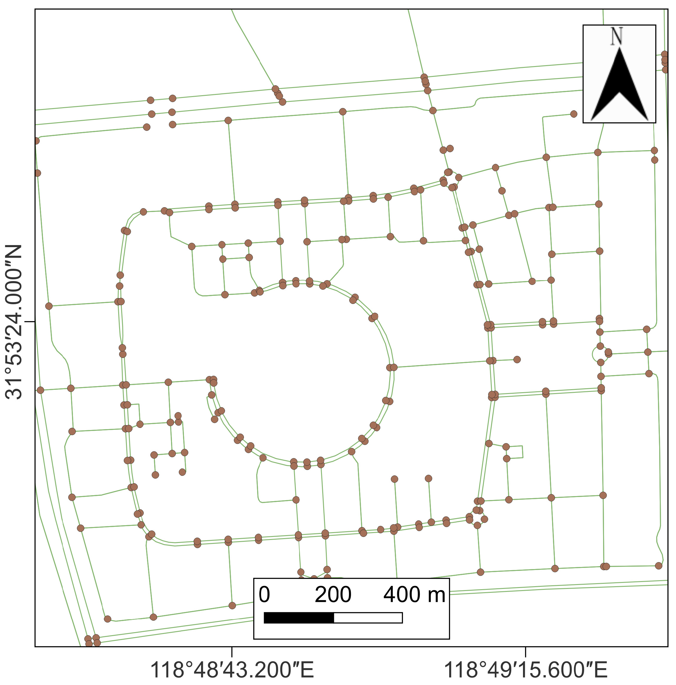
The heading angle correction strategy is aimed at obtaining the line segment of the road where the vehicle is located through map matching and using the road direction to correct the DR heading angle. After using the “osm2 gmns” library to process the raw OSM data, it is possible to produce a road network map that contains only line segments and points, as shown in Figure 2. It can be found that the straight road of the OSM network consists of short line segments, and most of the routes do not allow the lane information to be distinguished. In the curved part, the number of line segments of the OSM road network is higher, and the length is lower. When the vehicle is be driven along a curve, the heading angle of the OSM road drastically changes and cannot accurately represent the actual moving direction of the vehicle itself. Compared with curved roads, straight roads have longer line segments, while the direction changes of vehicles are fewer when driving. Therefore, the heading angle is corrected when driving along straight roads.
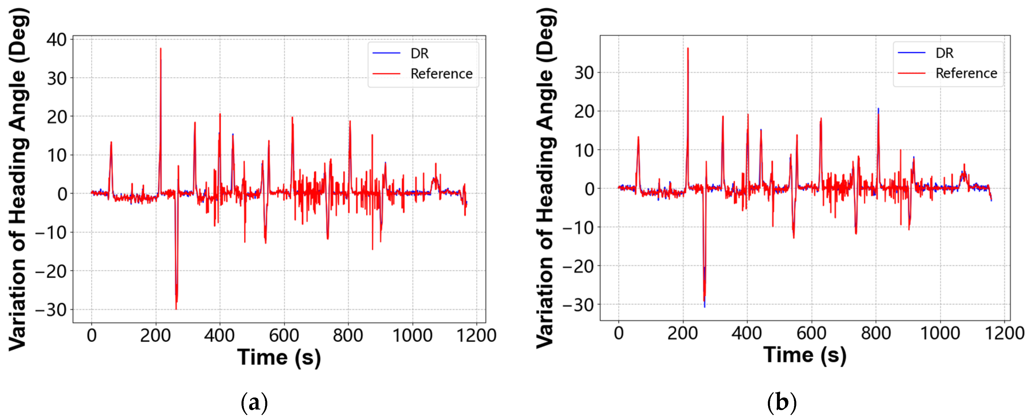
The first step is to assess the motion state of the vehicle, which is divided into two cases: straight and turning. Figure 3 shows the change of heading angle per second. The DR heading angle is obtained by updating the IMU data of the smartphone, while the reference heading angle is obtained through the difference between the adjacent positioning results of the vehicle-mounted geodetic GNSS receiver. When the vehicle turns, the actual heading angle change has a peak. Figure 3 shows that the peak of the DR heading angle change is the same as that of the geodetic GNSS receiver, indicating that the DR heading angle change can be used to determine whether the vehicle is turning.
In this work, the latest 5 s change of the DR heading angle is obtained. Then the cumulative change s u m ( d ψ D R ) of the heading angle within 5 s is calculated, as well as the times when the absolute value of the heading angle change is higher than 3 degrees. Thus, it is possible to determine whether the vehicle is located in a curve, according to the following formula:
{   c o u n t = 0 , s u m ( d ψ D R ) < 4 c u r v e c o u n t > = 2 , s u m ( d ψ D R ) > 6 c u r v e
The second step of heading angle correction is map matching. Map matching is usually performed using the traditional method point-to-point, point-to-line, or line-to-line. There are also probabilistic methods based on Hidden Markov. In order to ensure real time positioning, this work adopts the point-to-line matching method [24,25]. The accuracy and time consumption of map matching is mainly focused so that the designed map matching method contains many constraints. The detailed steps are as follows: Firstly, according to the latest positioning results, the road segments with a distance higher than 400 m or a length of lower than 15 m were filtered out. Then, according to the latest DR heading angle, the line segments with a heading angle different by more than 20 degrees were filtered out. Then, according to the projection of the point to the line segment, all the line segments that cannot be vertically projected were removed. Finally, the line segment with the shortest vertical projection distance was selected so that the direction of the road segment was used to correct the heading angle.
Due to the low position accuracy of the OSM road network, the map matching method may incorrectly match adjacent lanes. The heading angle correction needs only the direction information of the road, so matching it to the adjacent lane does not affect the final result.

2.4. RTK/DR Positioning Method

RTK/DR positioning method uses the standard Kalman filter for a combined navigation solution. The parameters to be estimated are position and velocity. The order of state update and measurement update are as follows:
{ X ^ k / k 1 = Φ k / k 1 X ^ k 1 P k / k 1 = Φ k / k 1 P k 1 Φ k / k 1 T + Γ k 1 Q k 1 Γ k 1 T
{ K k = P k / k 1 H k T ( H k P k / k 1 H k T + R k ) 1 X ^ k = X ^ k / k 1 + K k ( Z k H k X ^ k / k 1 ) P k = ( I K k H k ) P k / k 1
The system state transition matrix is constructed according to the uniform motion equation, as follows:
Φ k / k 1 = [ 1 0 0 0 d t R m + H k D R 0 0 1 0 d t ( R n + H k D R ) cos B k 0 0 0 0 1 0 0 1 0 0 0 1 0 0 0 0 0 0 1 0 0 0 0 0 0 1 ]
In complex urban environments, satellite signals are easily affected by multipath reflection and obstruction, resulting in drift and jumps of smartphone RTK. Incorrect RTK results will not only destroy the combination filter but also cause deviations in the subsequent range estimation, so it is necessary to stop the measurement update. The covariance matrix P k R T K , after robust RTK Kalman filtering, correlates with the positioning error. The position variance P k R T K is converted from the WGS84 coordinate system into the ENU coordinate system, so that the horizontal variance S p R T K is calculated:
S p R T K = ( S e R T K ) 2 + ( S n R T K ) 2
This work treats S p R T K as a rough prediction of horizontal position error. Figure 4 shows the comparison between S p R T K and actual horizontal position error. The green line (pre) represents horizontal variance S p R T K , and the red line (real) represents the actual RTK horizontal position error of the smartphone. It can be found that the overall S p R T K is higher than the actual horizontal error of the smartphone, even though, as far as the fluctuations, the two parameters are similar, and the performance is more consistent in areas affected by higher errors. The actual positioning error cannot be obtained during vehicle navigation. Therefore, according to the experimental results, this work regards S p R T K as an empirical indicator for assessing positioning quality. However, since the predicted horizontal position error is smaller than the actual error at some moments, additional information is needed to evaluate the positioning quality.
When the RTK positioning result jumps, its direction will drastically change, while the heading angle change of DR is closer to reality. Therefore, the difference of the heading angle change between RTK and DR can be used as an indicator to assess the positioning accuracy. The DR heading angle variation is also used to assess the vehicle motion state during the correction of this angle. Therefore, during the driving stage along a straight line, the RTK heading angle variation is directly used to determine whether there is a jump in the positioning result. Combined with the heading angle change information of RTK, this work adds a measurement update switch. When the vehicle is on a straight road, if S p R T K is higher than 2 and the RTK heading angle change exceeds 10 degrees, RTK/DR positioning method will perform only a state update but not a measurement update.

3. Results

3.1. Experimental Program

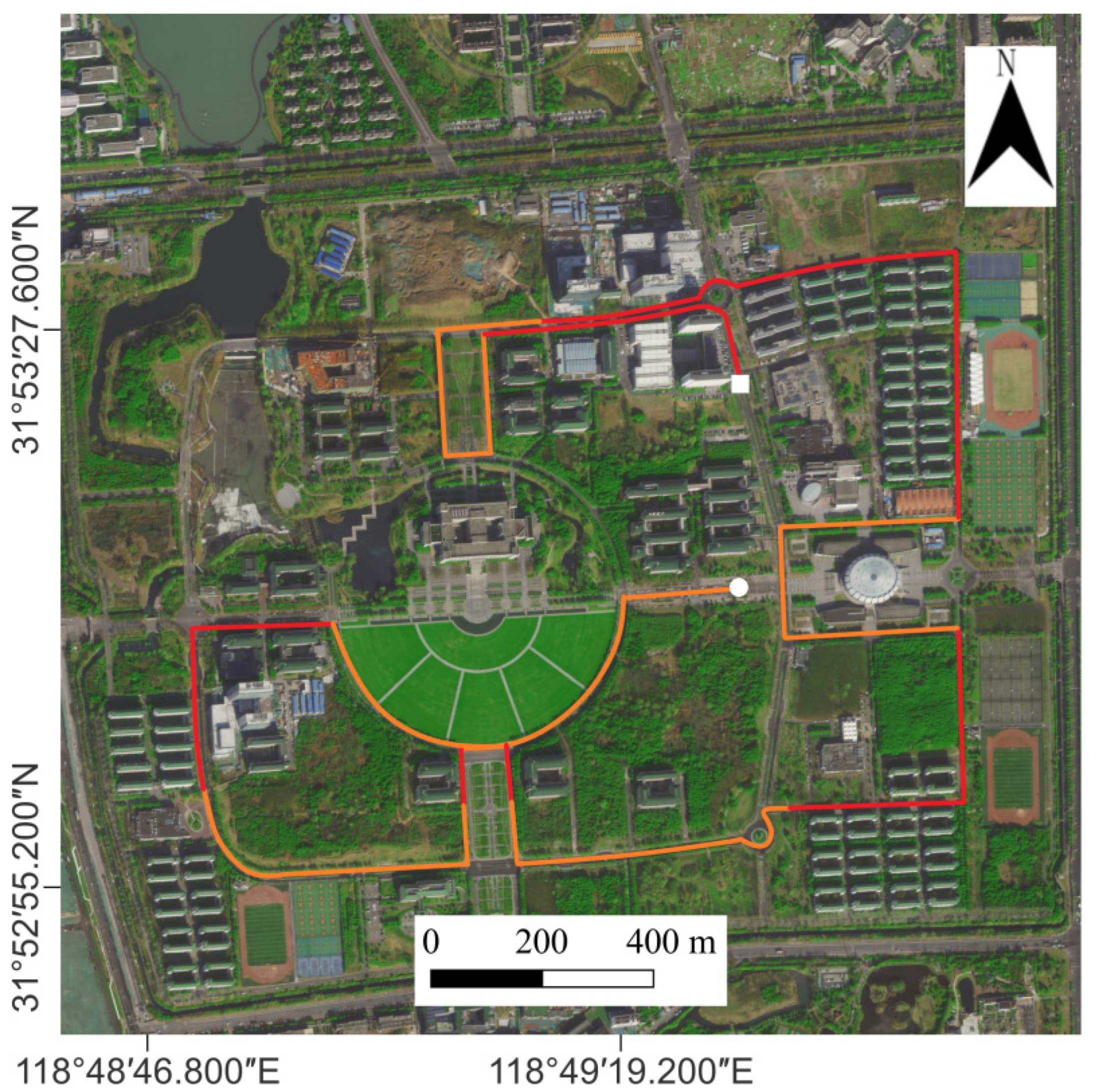
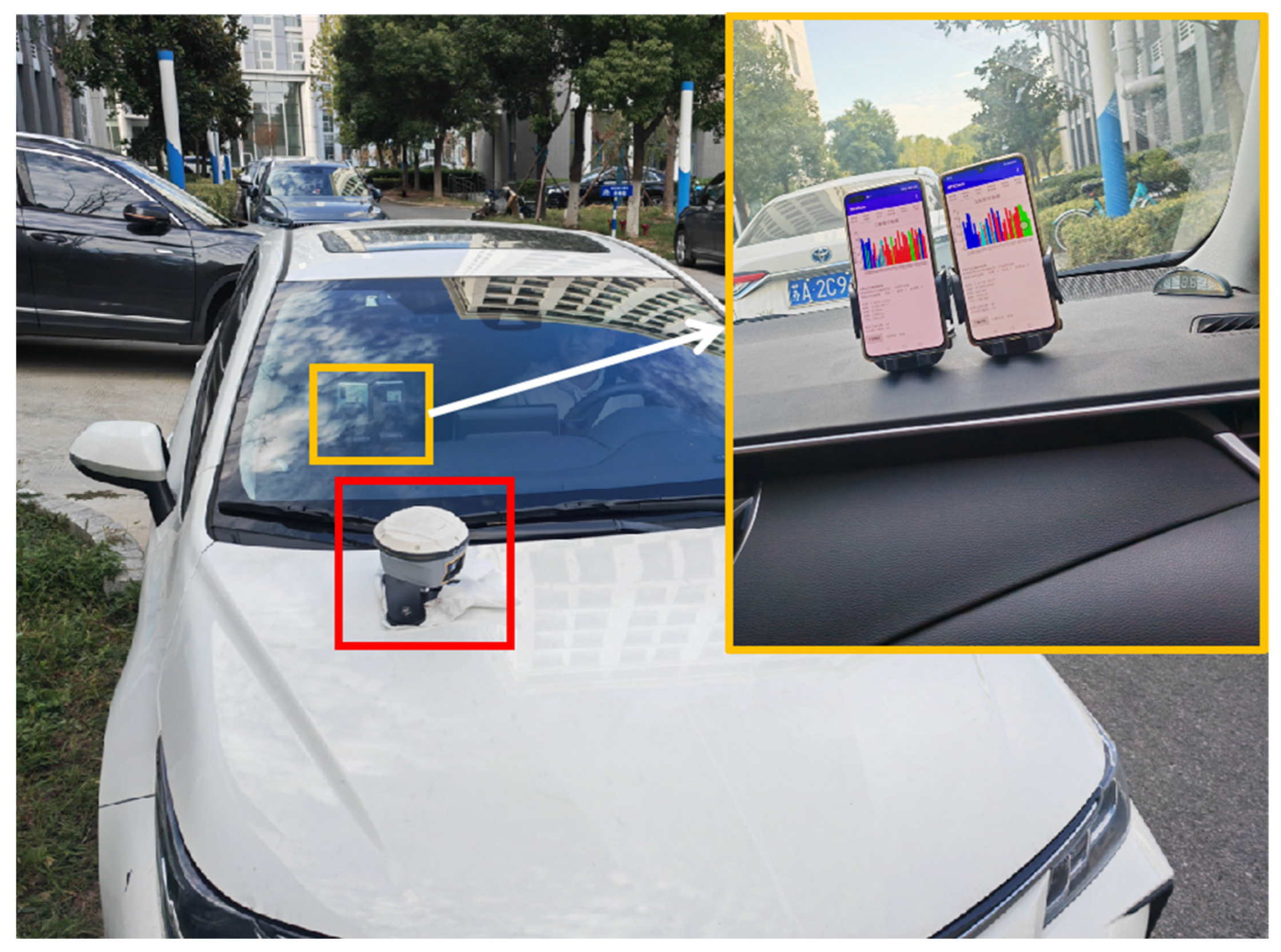
The experimental site is the campus of Southeast University in Nanjing, China, where the vehicle is driven along the route shown in Figure 5. The road is a single two-way lane with a total length of approximately 7200 m. The white circle is the starting point, and the white square is the ending point. The orange lines represent the open road section, while red one represents the complex road section. In order to obtain the reference trajectory of the smartphone, a geodesic GNSS receiver with a positioning accuracy of 3 to 5 cm is fixed on the hood of the car. Moreover, the horizontal distance between the smartphone and the geodetic GNSS receiver is measured, which is used to calculate the precise coordinates of the smartphone. The equipment installation is shown in Figure 6. Geodesic GNSS receivers are in the red square. Inside the car, two smartphones are affixed by brackets: Huawei P40 on the left and Huawei P30 on the right.
During the test, the smartphone integrates the acquisition module of satellite observation data and inertial navigation data, receives the observation data from the reference station in real time through the network, and performs RTK positioning. At the same time, smartphones internally store acceleration, angular velocity, magnetic field strength, gravitational acceleration, and GNSS observation information. RTK positioning frequency is 1 Hz, and the inertial sensor data sampling frequency is 100 Hz. The test was repeated four times, and the results of each test were completely independent. After the test, RTK/DR positioning solution was performed.
The antenna phase center of a smartphone is generally above the midpoint of the top. During dynamic positioning, since the smartphone’s pitch angle and roll angle are continually changing, the position of the antenna phase center is also continually changing. Since the actual pitch and roll angles cannot be obtained, it is almost impossible to measure the smartphone’s antenna phase center accurately. The smartphone is placed close to vertically, as shown in Figure 6, so this work ignores the influence of the antenna phase center on the horizontal positioning accuracy.

3.2. Effect of Heading Angle Correction

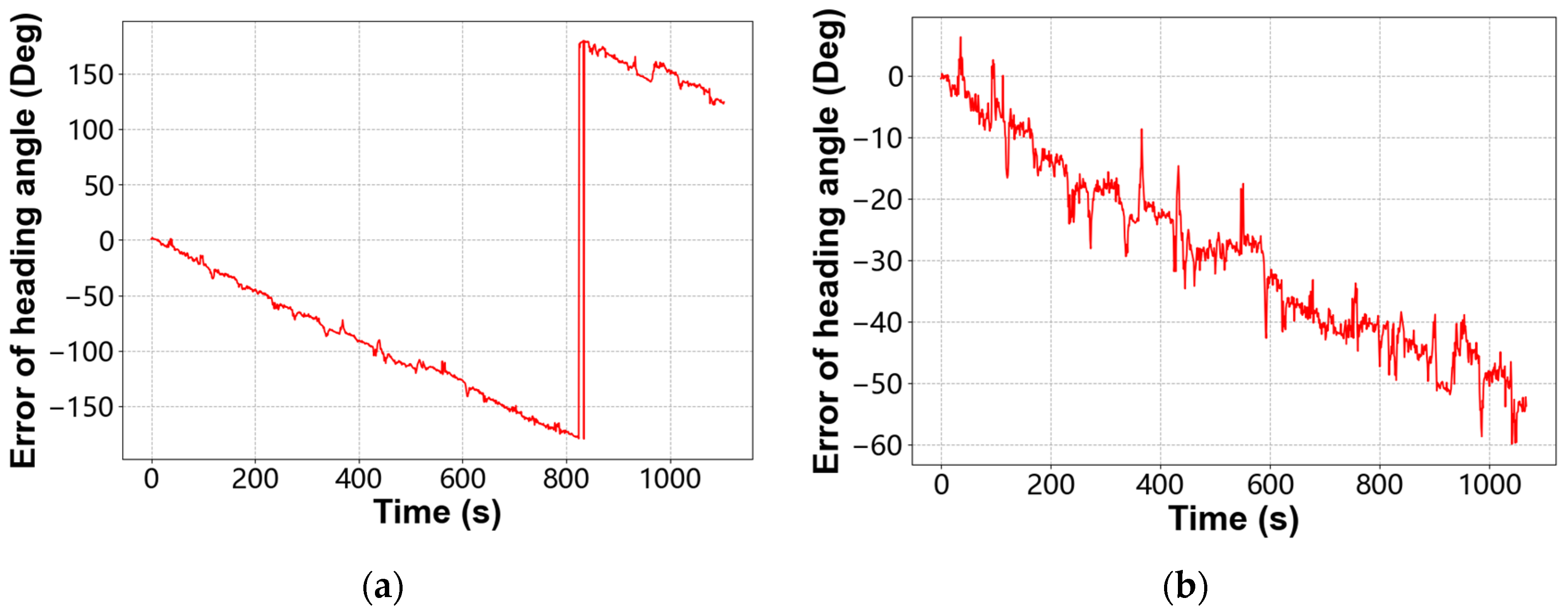
In DR, ψ B a s e represents the heading angle of the geodetic receiver; ψ D R represents the heading angle obtained by using only the IMU data for attitude update; and ψ r D R represents the heading angle after map correction. This work uses ψ B a s e as the actual value of the heading angle, so that the heading angle errors of the smartphones P30 and P40 are calculated when the heading angle correction is not performed. Due to a high amount of experimental data, Figure 7 shows the only results of the first group of tests. It can be found that the heading angle error updated by the angular velocity integration accumulates faster, and the noise levels of the two smartphones are quite different. At 600 s, P30 has a heading angle error higher than 120 degrees, while the P40 heading angle error also exceeds 30 degrees.
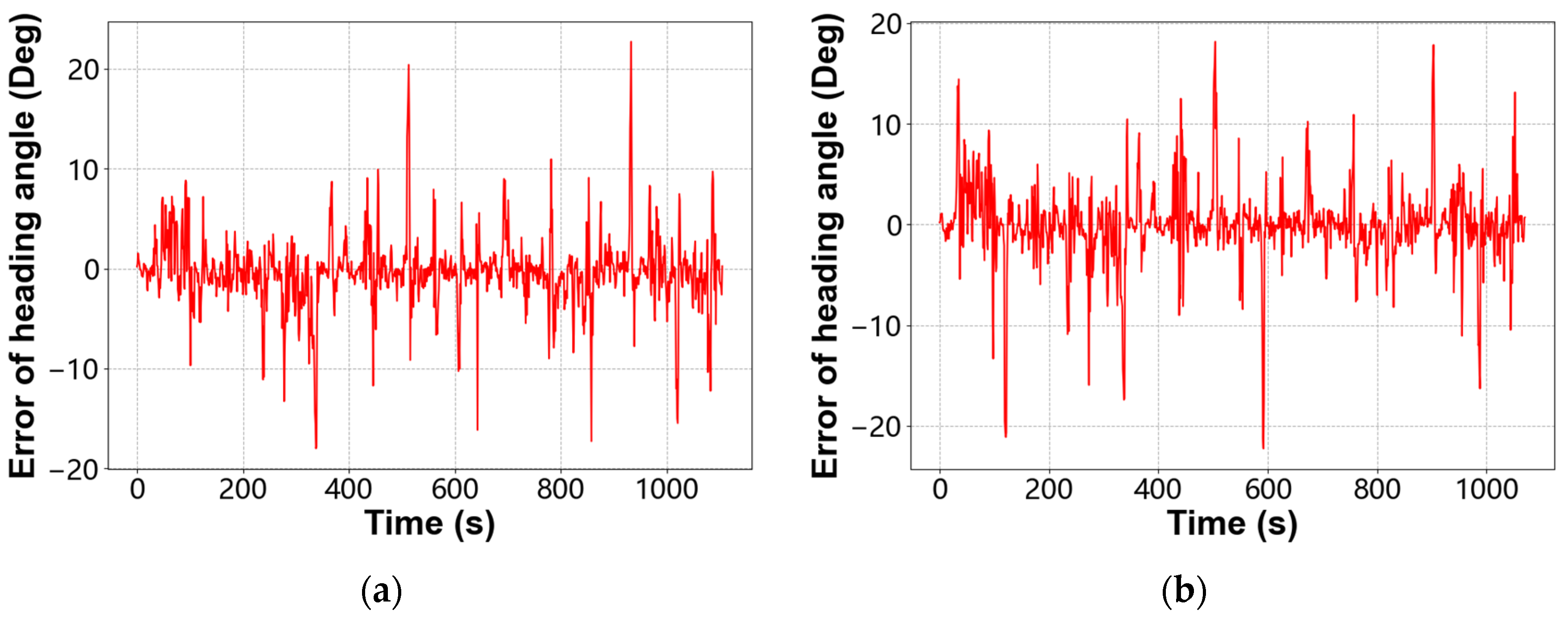
This work also analyzes the corrected heading angle error, as shown in Figure 8. After the correction, the accuracy of the heading angle is significantly improved and the error distribution is more even.
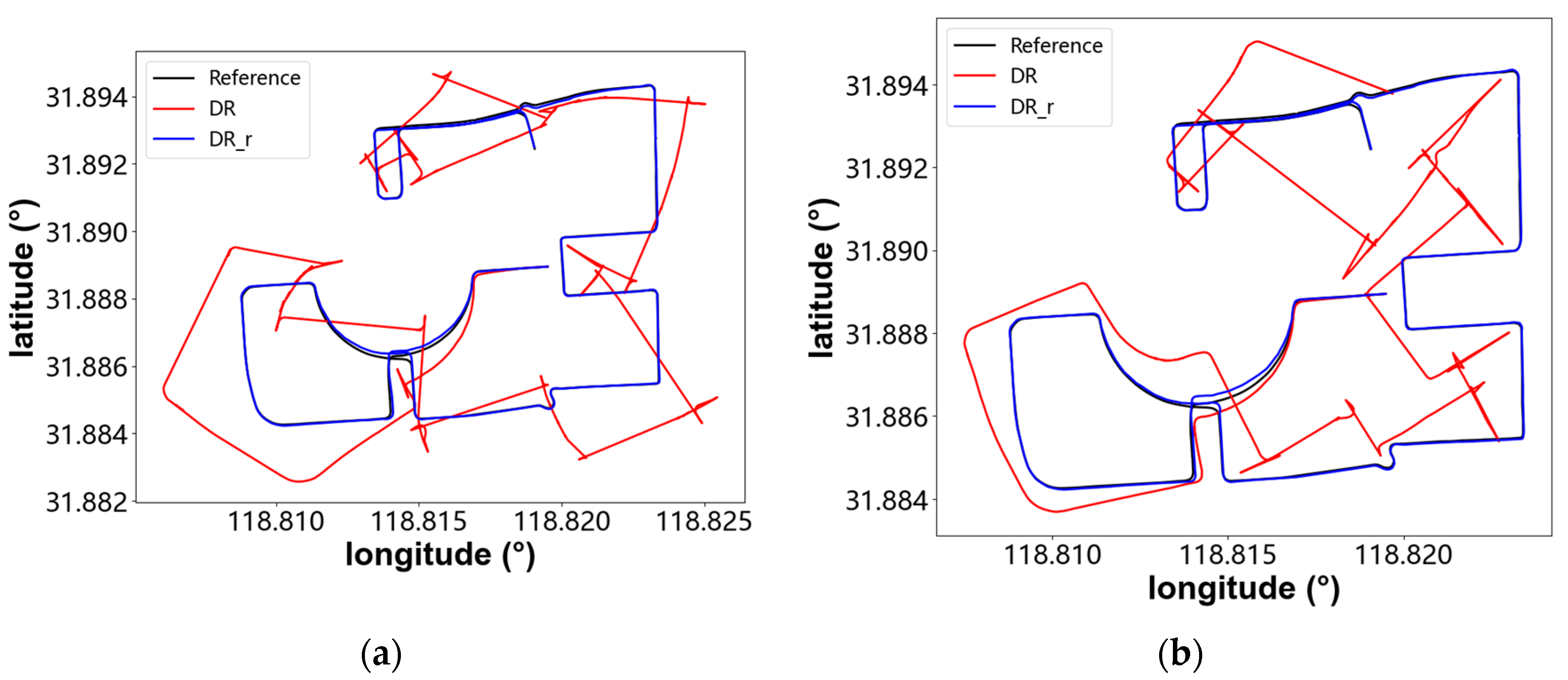
Figure 9 shows the horizontal trajectories of P30 and P40 dead reckoning during the first group of tests. The black line represents the geodetic GNSS receiver, while the red one represents pure DR, and the blue one represents DR_r after heading angle correction. It can be found that, as affected by the accumulation of heading angle errors, the trajectory of pure DR completely deviates from reality after a short period, losing the ability to navigate and determine positions. On the contrary, after using the map data to correct the heading angle, the trajectory of DR_r is more consistent with the benchmark.
In order to further verify the effect of heading angle correction, this work determines the heading angle and horizontal error of two smartphones during four groups of tests, as shown in Table 1. The statistical results show that the heading angle errors of the two smartphones are high and irregular. Similarly, the RMS horizontal positioning errors are both higher than 40 m. After using the OSM road direction information to correct the heading angle, the error of this angle is limited to approximately 2 degrees and the horizontal positioning error is limited to approximately 5 m. Compared with the DR before correction, the smartphone heading angle and horizontal positioning accuracy are highly improved, and the results of each set of tests are also closer. The test results show that the heading angle correction method designed in this work is relatively stable, can weaken the error accumulation velocity of DR, and provides a good foundation for the RTK/DR positioning method.

3.3. Statistics and Analysis of Smartphone Positioning Error

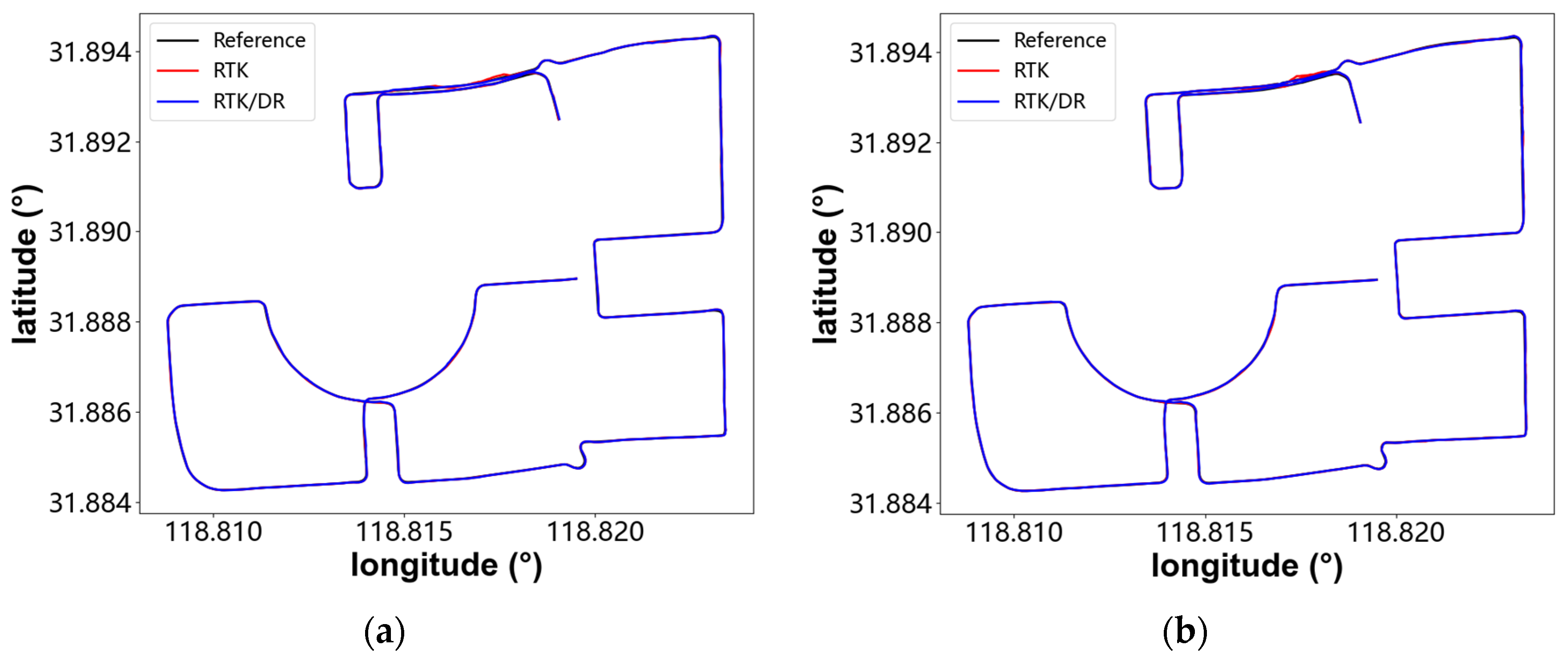
Based on eight sets of test results, RTK/DR positioning performance, in terms of direction, velocity, and position, was analysed. The DR heading angles were corrected using the map road network. Figure 10 shows the positioning results of the two smartphones in the first set of tests. The black line represents the accurate trajectory, the red one represents only RTK positioning, and the blue one represents RTK/DR positioning. Overall, the RTK and RTK/DR horizontal trajectories almost coincide with the accurate trajectories, so it is difficult to see the actual accuracy difference from the trajectory graph alone.
In order to further compare the RTK/DR positioning performance to RTK, this work determines the direction error and velocity error of the two smartphones in four in-vehicle navigation tests, as shown in Table 2.
The heading angle of RTK/DR positioning method corresponds to that of DR_r, differently from the RTK positioning result. The RMS heading angle error of RTK is between 2 and 3 degrees, while the overall change is relatively stable. Compared with RTK, the RMS heading angle error of RTK/DR decreases in each group of tests, while the heading angle error of the three groups of tests decreases to within 2 degrees. Regarding the positioning accuracy change, the heading angle accuracy of the eight tests is improved, and during five groups of tests, the accuracy is improved by more than 20%, whereas the test P30-3 records the maximum improvement, i.e., 39.3%. The combination of smartphones IMU data and OSM data provides smartphones with a more accurate heading angle.
When the vehicle normally moves, there is no lateral drift and the horizontal velocity equals the forward one. The velocity measured by RTK/DR is the projection of RTK velocity on the direction of the heading angle measured by DR. The difference between the two velocities is determined by the direction difference between RTK and DR. The results of the eight tests show that the horizontal velocity measured by RTK/DR is almost the same as that measured by RTK, and most of the changes do not exceed 2%. Only the horizontal velocity of the test P40-2 has a 4.7% increase.
The effect of heading angle and velocity on the position is reflected mainly in the lateral and forward directions, so the positioning error should be assessed according to the lateral and forward directions, rather than the East and North directions. Table 3 shows the positioning error of the two smartphones and the accuracy variation of RTK/DR. The RTK lateral error RMS is higher than the forward error RMS, indicating that there are many lateral drifts and jumps in the positioning results, due mainly to the environment on both road sides. In the eight sets of test results, the RMS fluctuation of the smartphone RTK positioning horizontal positioning error is significant, the minimum value is 1.065 m, and the maximum value is 2.343 m.
Compared with the RTK results, RTK/DR achieves significant performance differences, in terms of lateral and forward error. The lateral accuracy of RTK/DR is better than that of RTK. The lateral accuracy of P30 is improved by 10%, while the lateral accuracy of P40 is improved by more than 20%. The forward accuracy of RTK/DR slightly decreases, and the decrease achieved by using both smartphones is within 1%. The horizontal accuracy of RTK/DR is better than RTK in each set of tests. P30 has only a tiny improvement of 2–5%, while P40 has a 10–30% improvement.
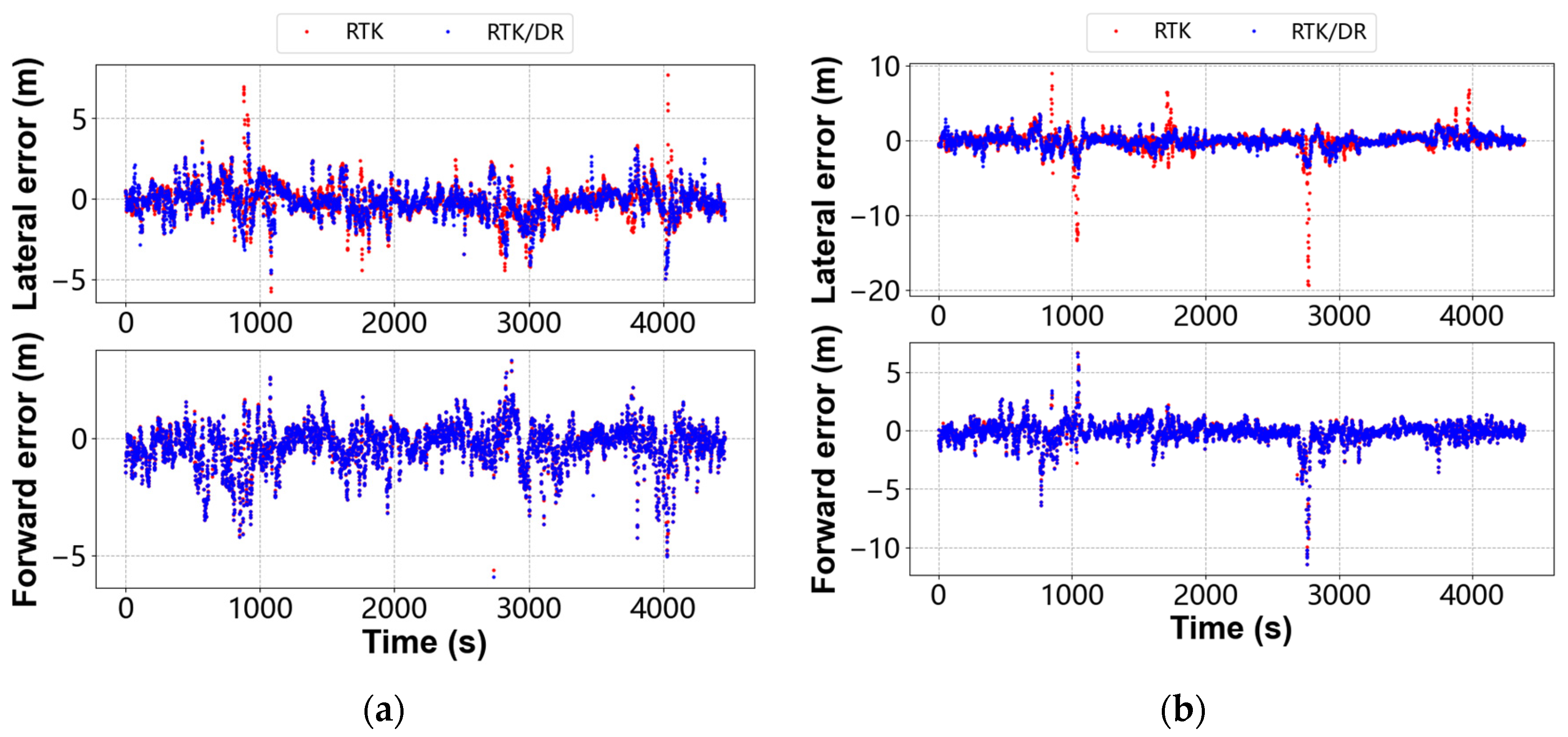
The four times of vehicle positioning results were merged, so that they were displayed according to the smartphone model, as shown in Figure 11 and Table 4. It can be seen that the lateral error of RTK/DR is significantly lower than that of RTK, while the error fluctuation is slight. However, the forward error distributions of RTK/DR and RTK are highly consistent, so the difference between the two positioning methods cannot be identified. The horizontal error RMS of the two smartphones is almost identical, i.e., lower than 1.3 m. Compared with the RTK results, the RTK/DR horizontal accuracy of the P30 is improved by 5.9%, while the RTK/DR horizontal accuracy of the P40 is improved by 44.4%.
Combined with the error analysis of the heading angle and velocity, it can be deduced that the heading angle affects mainly the lateral positioning accuracy, so the accuracy improvement of the heading angle promotes the improvement of the lateral accuracy. The velocity mainly affects the forward positioning accuracy. According to the calculation formula of velocity, the velocity noise of RTK/DR includes the velocity noise of RTK and the heading angle noise of DR, so that the forward accuracy of RTK/DR is lower than that of RTK.
Smartphone horizontal positioning accuracy is also affected by the measurement update switch. When RTK sharply jumps, if the measurement update is not turned off in time, RTK/DR will carry the RTK positioning error of the previous epoch, resulting in error accumulation. Table 5 shows the number of epochs in which the measurement update is turned off in the eight sets of tests. Although the driving routes of the vehicle are the same, the number of stop measurement updates in each group of tests is quite different. Among them, the number of stop measurement updates for P40-1 and P40-2 reaches more than 400 times, accounting for more than 35%. There are a total of 8851 epochs of positioning results, of which 2534 epochs automatically stop the measurement update, accounting for 28.6%. As far as the results of horizontal position accuracy in Table 3 and Table 5, the horizontal position accuracy of RTK during the closed measurement update period is lower than the overall accuracy, which shows that the measurement update switch can effectively identify the period with significant RTK error. In addition, the positioning accuracy of DR in each group of tests is higher than that of RTK, which shows that DR can maintain reliable positioning when RTK positioning results are not good.
Figure 11 shows that the error fluctuation of the RTK positioning results of P40 is more severe than that of P30. Therefore, the number of measurement update stops for P40 is higher than that for P30 in each test. Ultimately, the positioning accuracy difference between RTK/DR and RTK of P40 is more significant than that of P30.

4. Discussion

This paper studies in-vehicle smartphone positioning in urban environments and proposes an RTK/DR positioning method that integrates OSM road network information. The test results show that the accuracy of heading angle and position achieved by using this method is higher than conventional RTK positioning results: the heading angle accuracy reaches 2 degrees, and the horizontal positioning error is lower than 1.5 m.
In DR, the raw IMU data of the smartphone contain a relatively high noise, and attitude error calculated by angular velocity integral accumulates faster. It can be deduced from Figure 7 that, without any processing, the heading angle error of the smartphone reaches 30 degrees in 600 s. At the same time, it was possible to find that, although the heading angle of the smartphone is inaccurate, its variation per second can accurately reflect the turning situation of the vehicle, as shown in Figure 3. The direction of the OSM road network is more reliable in the straight part, even though the direction of the turning part does not match the actual value. Therefore, this work uses OSM road direction along the straight line to correct the heading angle. The statistical results in Table 1 show that this method highly improves the heading angle accuracy and makes the trajectory of the DR more parallel and consistent with the benchmark.
In the RTK/DR positioning method, the measurement update switch effectively detects multiple jump points of RTK positioning. According to Table 4, the time when the measurement update is stopped accounts for 28.6% of the total time, during which DR performs state updates to maintain vehicle navigation. Finally, according to the statistical results shown in Figure 9 and Table 3, it can be deduced that the heading angle correction method and the measurement update switch can effectively improve the lateral positioning accuracy. However, as the velocity includes RTK velocity and heading angle error, there is a decrease of the forward accuracy of approximately 1%. RTK/DR has a better horizontal positioning accuracy than RTK and is more reliable in urban environments.
Experimental results show that the method described in this paper still has some limitations: The velocity update of DR is seriously dependent on the velocity used by Doppler measurement, so there is no improvement of the forward positioning accuracy. Moreover, when the vehicle turns, there is a lack of suitable maps to correct the heading angle, so the DR quickly accumulates direction errors in the roads having long turns. Thus, in the near future, it is necessary to continue to study the multi-source data fusion positioning of in-vehicle smartphones in order to improve its direction, velocity, and positioning accuracy.

5. Conclusions

In the in-vehicle smartphone navigation scenario, as RTK is prone to drift or jump in complex environments and the DR heading angle is prone to divergence, this paper proposes an RTK/DR positioning method that integrates OSM road network information. RTK/DR uses standard Kalman filter estimation, and there are two main points of optimisation in the positioning process. The first point of optimisation is to use the DR heading angle change in order to assess the turning situation, obtain the OSM road line segment through map matching and, finally, use the direction of the matched road to correct the heading angle. The second point of optimisation is to combine the covariance matrix of RTK positioning, vehicle motion status, and RTK heading angle change information in order to automatically determine the reliability of RTK positioning results and stop measurement updates when the positioning results significantly jump.
Two smartphones were used, i.e., Huawei P30 and P40, and four positioning tests were carried out in order to verify the proposed algorithm. From the test results, it was possible to deduce that the accuracy of the smartphone DR heading angle is highly improved after the OSM road network correction: in the eight sets of test results, the smartphone heading angle accuracy is better than that of RTK, and the improvement rate of six sets of tests is higher than 15%. Thanks to the heading angle correction and measurement update switch, the RTK/DR described in this paper is better than RTK in both lateral and horizontal accuracy. The lateral accuracy of P40 is improved by more than 20%, and the horizontal accuracy is improved by more than 10%. As the DR velocity update cannot remove the dependence on RTK positioning, the forward positioning accuracy slightly decreases. Future research will attempt to solve this problem.

Author Contributions

Conceptualization, C.G. and F.W.; methodology, F.W.; software, F.W.; validation, F.W.; formal analysis, F.W.; investigation, F.W.; resources, C.G. and F.W.; data curation, C.G. and F.W.; writing—original draft preparation, F.W.; writing—review and editing, C.G., F.W., R.Z. and R.S.; visualization, F.W., Q.L. and L.G.; supervision, C.G. and F.W.; project administration, C.G., F.W. and J.W.; funding acquisition, C.G., F.W. and J.W. All authors have read and agreed to the published version of the manuscript.

Funding

This research was funded by the Ministry of Education—China Mobile Research Fund (MCM20200J01).

Data Availability Statement

The data supporting the findings of this study are made available by the corresponding author upon reasonable request.

Acknowledgments

The authors thank the IGS data center of Wuhan University for its support of real-time precise ephemeris.

Conflicts of Interest

The authors declare no conflict of interest.

References

  1. Zhu, B.; Tao, X.; Zhao, J.; Ke, M.; Wang, H.; Deng, W. An Integrated GNSS/UWB/DR/VMM Positioning Strategy for Intelligent Vehicles. IEEE Trans. Veh. Technol. 2020, 69, 10842–10853. [Google Scholar] [CrossRef]
  2. Yan, G.; Wang, J.; Zhou, X. High-Precision Simulator for Strapdown Inertial Navigation Systems Based on Real Dynamics from GNSS and IMU Integration. In China Satellite Navigation Conference (CSNC) 2015 Proceedings: Volume III; Sun, J., Liu, J., Fan, S., Lu, X., Eds.; Lecture Notes in Electrical Engineering; Springer: Berlin/Heidelberg, Germany, 2015; Volume 342, pp. 789–799. [Google Scholar] [CrossRef]
  3. Liu, X.; Sun, X.; Xia, X. LiDAR Point’s Elliptical Error Model and Laser Positioning for Autonomous Vehicles. Meas. Sci. Technol. 2021, 32, 035107. [Google Scholar] [CrossRef]
  4. Yao, Z.; Zhang, H. Performance analysis on vehicle GNSS/INS integrated navigation system aided by odometer. J. Geod. Geodyn. 2018, 38, 206–210. [Google Scholar]
  5. Chang, L.; Niu, X.; Liu, T. GNSS/IMU/ODO/LiDAR-SLAM Integrated Navigation System Using IMU/ODO Pre-Integration. Sensors 2020, 20, 4702. [Google Scholar] [CrossRef] [PubMed]
  6. Gao, C.; Chen, B.; Liu, Y. Android smartphone GNSS high-precision real-time dynamic positioning. Acta Geod. Cartogr. Sin. 2021, 50, 18–26. [Google Scholar]
  7. Paziewski, J.; Fortunato, M.; Mazzoni, A.; Odolinski, R. An Analysis of Multi-GNSS Observations Tracked by Recent Android Smartphones and Smartphone-Only Relative Positioning Results. Measurement 2021, 175, 109162. [Google Scholar] [CrossRef]
  8. Paziewski, J.; Sieradzki, R.; Baryla, R. Signal Characterization and Assessment of Code GNSS Positioning with Low-Power Consumption Smartphones. GPS Solut. 2019, 23, 98. [Google Scholar] [CrossRef] [Green Version]
  9. Lachapelle, G.; Gratton, P.; Horrelt, J.; Lemieux, E.; Broumandan, A. Evaluation of a Low Cost Hand Held Unit with GNSS Raw Data Capability and Comparison with an Android Smartphone. Sensors 2018, 18, 4185. [Google Scholar] [CrossRef] [PubMed] [Green Version]
  10. Groves, P.D.; Adjrad, M. RETRACTED ARTICLE: Likelihood-Based GNSS Positioning Using LOS/NLOS Predictions from 3D Mapping and Pseudoranges. GPS Solut. 2017, 21, 1805–1816. [Google Scholar] [CrossRef] [Green Version]
  11. Hsu, L.-T.; Gu, Y.; Huang, Y.; Kamijo, S. Urban Pedestrian Navigation Using Smartphone-Based Dead Reckoning and 3-D Map-Aided GNSS. IEEE Sens. J. 2016, 16, 1281–1293. [Google Scholar] [CrossRef]
  12. Jeon, J.; Hwang, Y.; Jeong, Y.; Park, S.; Kweon, I.S.; Choi, S.B. Lane Detection Aided Online Dead Reckoning for GNSS Denied Environments. Sensors 2021, 21, 6805. [Google Scholar] [CrossRef] [PubMed]
  13. Liu, J.; Cai, B.G.; Wen, Y.H.; Wang, J. Integrating DSRC and Dead-Reckoning for Cooperative Vehicle Positioning under GNSS-Challenged Vehicular Environments. IJAHUC 2015, 19, 111. [Google Scholar] [CrossRef]
  14. Wang, J.; Bai, M.; Huang, Y.; Chen, Z.; Zhan, Y.; Xia, X. Study on GNSS/DR Integrated Navigation. In Proceedings of the 2017 29th Chinese Control And Decision Conference (CCDC), Chongqing, China, 28–30 May 2017; pp. 4973–4979. [Google Scholar] [CrossRef]
  15. Zhang, Q.; Niu, X. Research on Accuracy Enhancement of Low-Cost MEMS INS/GNSS Integration for Land Vehicle Navigation. In Proceedings of the 2018 IEEE/ION Position, Location and Navigation Symposium (PLANS), Monterey, CA, USA, 23–26 April 2018; pp. 891–898. [Google Scholar] [CrossRef]
  16. Salib, A.; Moussa, M.; Moussa, A.; El-Sheimy, N. Visual Odometry/Inertial Integration for Enhanced Land Vehicle Navigation in GNSS Denied Environment. In Proceedings of the 2020 IEEE 92nd Vehicular Technology Conference (VTC2020-Fall), Victoria, BC, Canada, 18 November–16 December 2020; pp. 1–6. [Google Scholar] [CrossRef]
  17. Zeng, Q.; Zeng, S.; Liu, J.; Chen, R.; Meng, Q.; Wang, J. Heading correction method for smartphone based on gravity assisting and simulated zero-velocity updating. J. Chin. Inert. Technol. 2018, 26, 289–294. [Google Scholar]
  18. Peng, Y. Research on Multi-Sensor Fusion Positioning Algorithm of GNSS/INS/camera Lane Line; Wuhan University: Wuhan, China, 2020. [Google Scholar]
  19. Peng, Y.; Pan, S.; Gao, W.; Qiao, L.; Tan, Y.; Sun, Y. Heading angle estimation for vehicles based online detection and digital map matching. J. Electron. Meas. Instrum. 2022, 36, 194–201. [Google Scholar]
  20. Xu, Q.; Li, X.; Sun, Z.; Hu, W.; Chang, B. A Novel Heading Angle Estimation Methodology for Land Vehicles Based on Deep Learning and Enhanced Digital Map. IEEE Access 2019, 7, 138567–138578. [Google Scholar] [CrossRef]
  21. Kong, Q. Quality Analysis on Crowd Sourcing Geographic Data with OSM Road Network Data; Shandong University of Science and Technology: Qingdao, China, 2020. [Google Scholar]
  22. Liu, Y. Research on High Precision Real-Time Fusion Positioning and Indoor and Outdoor Switching of Android Smartphone; Southeast University: Nanjing, China, 2021. [Google Scholar] [CrossRef]
  23. Zhang, X.; Guo, F.; Li, P.; Zuo, X. Real-time quality control procedure for GNSS precise point positioning. Geomat. Inf. Sci. Wuhan Univ. 2012, 37, 940–944+1013. [Google Scholar]
  24. Li, J. Research on OpenStreetMap Based Map Matching Algorithm and Its Implementation; Beijing University of Technology: Beijing, China, 2017. [Google Scholar]
  25. Xu, J.; Ta, N.; Xing, C.; Zhang, Y. Online Map Matching Algorithm Using Segment Angle Based on Hidden Markov Model. In Proceedings of the 2017 14th Web Information Systems and Applications Conference (WISA), Liuzhou, China, 11–12 November 2017; pp. 50–55. [Google Scholar] [CrossRef]
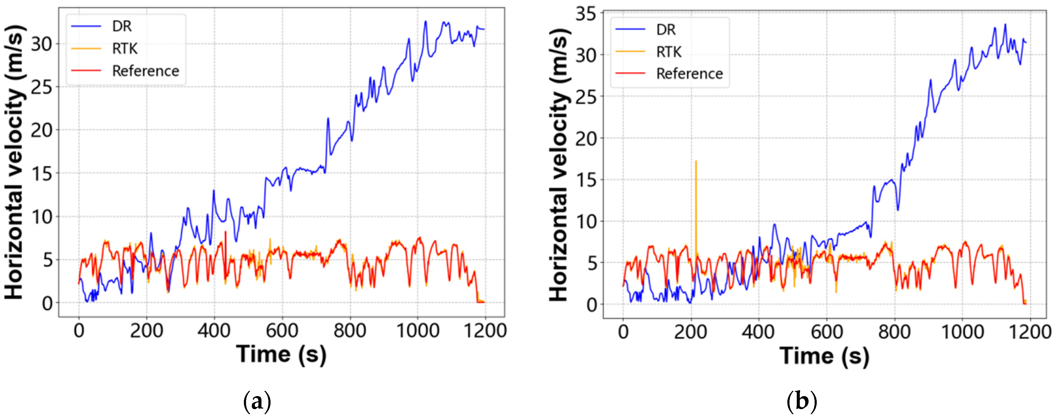
Figure 1. Horizontal velocity comparison. (a) Smartphone Huawei P30; (b) Smartphone Huawei P40.
Remotesensing 15 00398 g001
Figure 2. OSM road network.
Remotesensing 15 00398 g002
Figure 3. Variation of heading angle. (a) Smartphone Huawei P30; (b) Smartphone Huawei P40.
Remotesensing 15 00398 g003
Figure 4. Comparison of horizontal errors. (a) Smartphone Huawei P30; (b) Smartphone Huawei P40.
Remotesensing 15 00398 g004
Figure 5. Vehicle driving route.
Remotesensing 15 00398 g005
Figure 6. Equipment placement.
Remotesensing 15 00398 g006
Figure 7. Heading angle error before correction. (a) Smartphone Huawei P30; (b) Smartphone Huawei P40.
Remotesensing 15 00398 g007
Figure 8. Heading angle error after correction. (a) Smartphone Huawei P30; (b) Smartphone Huawei P40.
Remotesensing 15 00398 g008
Figure 9. Horizontal positioning trajectory comparison. (a) Smartphone Huawei P30; (b) Smartphone Huawei P40.
Remotesensing 15 00398 g009
Figure 10. RTK/DR positioning track. (a) Smartphone Huawei P30; (b) Smartphone Huawei P40.
Remotesensing 15 00398 g010
Figure 11. RTK/DR positioning error along lateral and forward direction. (a) Smartphone Huawei P30; (b) Smartphone Huawei P40.
Remotesensing 15 00398 g011
Table 1. Error statistics for heading angle and horizontal positioning error.
Test
Number
Heading Angle Error RMS
(Degrees)
Horizontal Positioning Error RMS
(m)
DRDR_rDRDR_r
P30-1106.1812.215200.8545.668
P30-232.7022.103217.4306.636
P30-37.6902.081106.6294.356
P30-45.2651.62942.1874.832
P40-129.0062.346183.6605.506
P40-211.7922.29393.3135.761
P40-37.9661.80886.4635.064
P40-44.6091.53946.2765.622
Table 2. Statistics of heading angle and velocity error achieved by using RTK/DR positioning method.
Test
Number
Heading Angle Error
RMS (Degrees)
Accuracy ChangeVelocity Error
RMS (m/s)
Accuracy Change
RTKRTK/DRRTKRTK/DR
P30-12.3922.2157.4%2.8042.813−0.3%
P30-22.3342.1039.9%0.2420.245−1.1%
P30-32.8972.08128.2%0.8040.805−0.7%
P30-42.3531.62930.8%0.3130.314−0.2%
P40-12.8202.34616.8%2.7432.745−0.1%
P40-22.8962.29320.8%0.2760.2634.7%
P40-32.9771.80839.3%0.5020.4990.7%
P40-42.1951.53929.9%0.2550.2550.0%
Table 3. Statistics of positioning error RMS.
Test
Number
RTK (m)RTK/DR (m)RTK/DR Accuracy Variation
LateralForward HorizontalLateralForward HorizontalLateralForwardHorizontal
P30-11.1661.1221.6191.0491.1291.54210.0%−0.6%4.7%
P30-20.8340.7421.1160.7680.7451.0707.9%−0.5%4.1%
P30-31.0410.8681.3560.9900.8711.3194.9%−0.3%2.7%
P30-40.9570.9341.3370.9080.9351.3045.0%−0.1%2.5%
P40-11.7321.1212.0631.0661.1311.55438.4%−0.8%24.6%
P40-20.8880.6181.0820.6920.6230.93122.0%−0.8%13.9%
P40-31.8521.4352.3430.9101.4401.70450.8%−0.4%27.3%
P40-40.9260.5261.0650.7240.5290.89621.8%−0.5%15.8%
Table 4. Statistics of positioning error RMS of Smartphones Huawei P30 and P40.
Smartphone ModelRTK (m)RTK/DR (m)
LateralForward HorizontalLateralForward Horizontal
P301.0120.8521.3230.9020.8591.245
P402.0421.0162.2810.7421.0271.267
Table 5. Number of epochs for stop of measurement updates.
Test
Number
Total Number
of Epochs
Number of
Stop Epochs
Horizontal Position Accuracy
DRRTK/DR
P30-111112551.7392.017
P30-211942031.2161.382
P30-311703321.6691.673
P30-49842211.7251.773
P40-110734281.6192.737
P40-211794361.0931.455
P40-311603902.6303.817
P40-49802691.0631.496
Disclaimer/Publisher’s Note: The statements, opinions and data contained in all publications are solely those of the individual author(s) and contributor(s) and not of MDPI and/or the editor(s). MDPI and/or the editor(s) disclaim responsibility for any injury to people or property resulting from any ideas, methods, instructions or products referred to in the content.