

Range Sidelobe Iterative Suppression Algorithm for Extended Target with Non-Grid Multiple Scattering Points

Abstract
:1. Introduction
2. Model
Target Echo Signal Model of Non-Grid Multiple Scattering Points
3. Methods
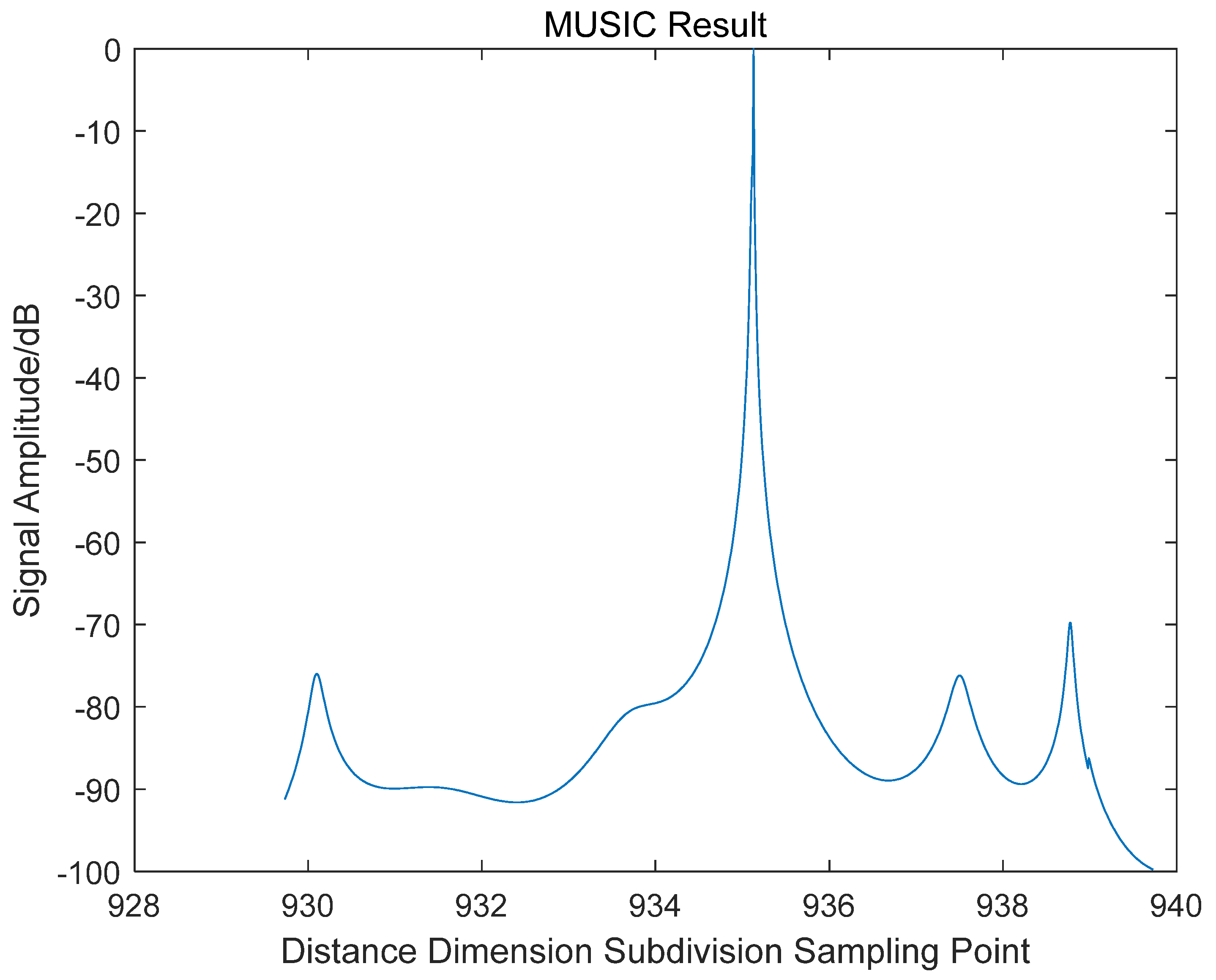
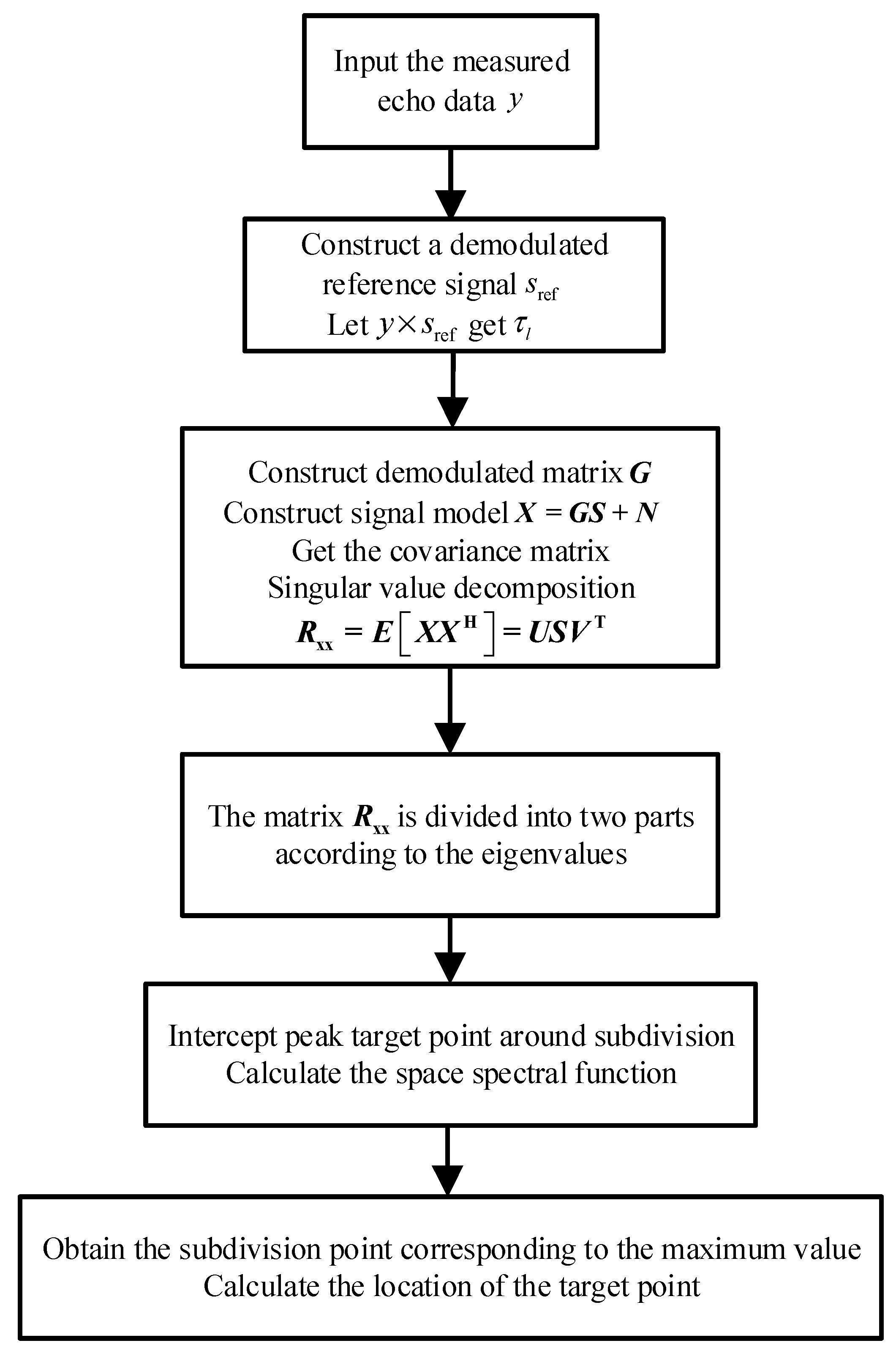
3.1. Scattering Points Offset Estimation Algorithm Based on Modified MUSIC
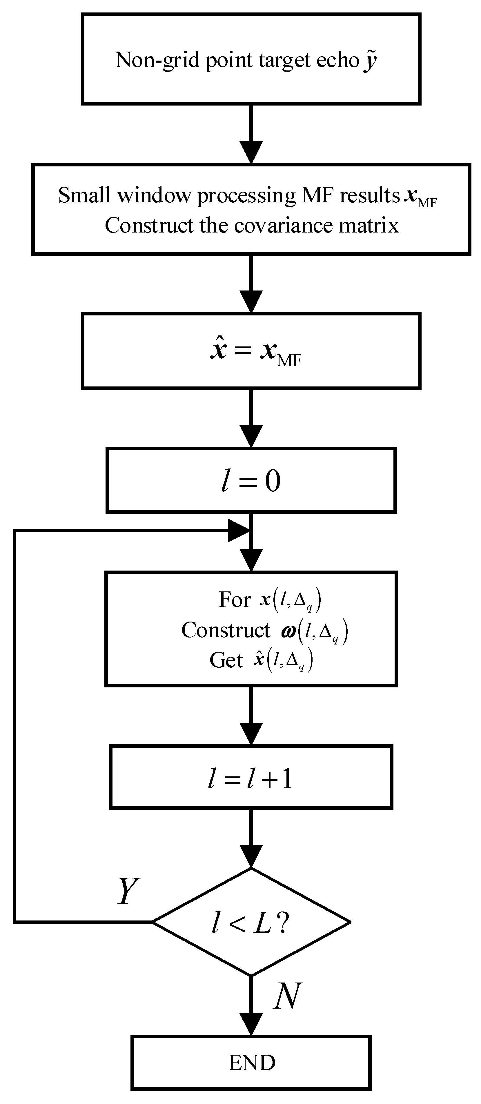
3.2. Target Sidelobe Iterative Suppression Algorithm Based on Non-Grid Model
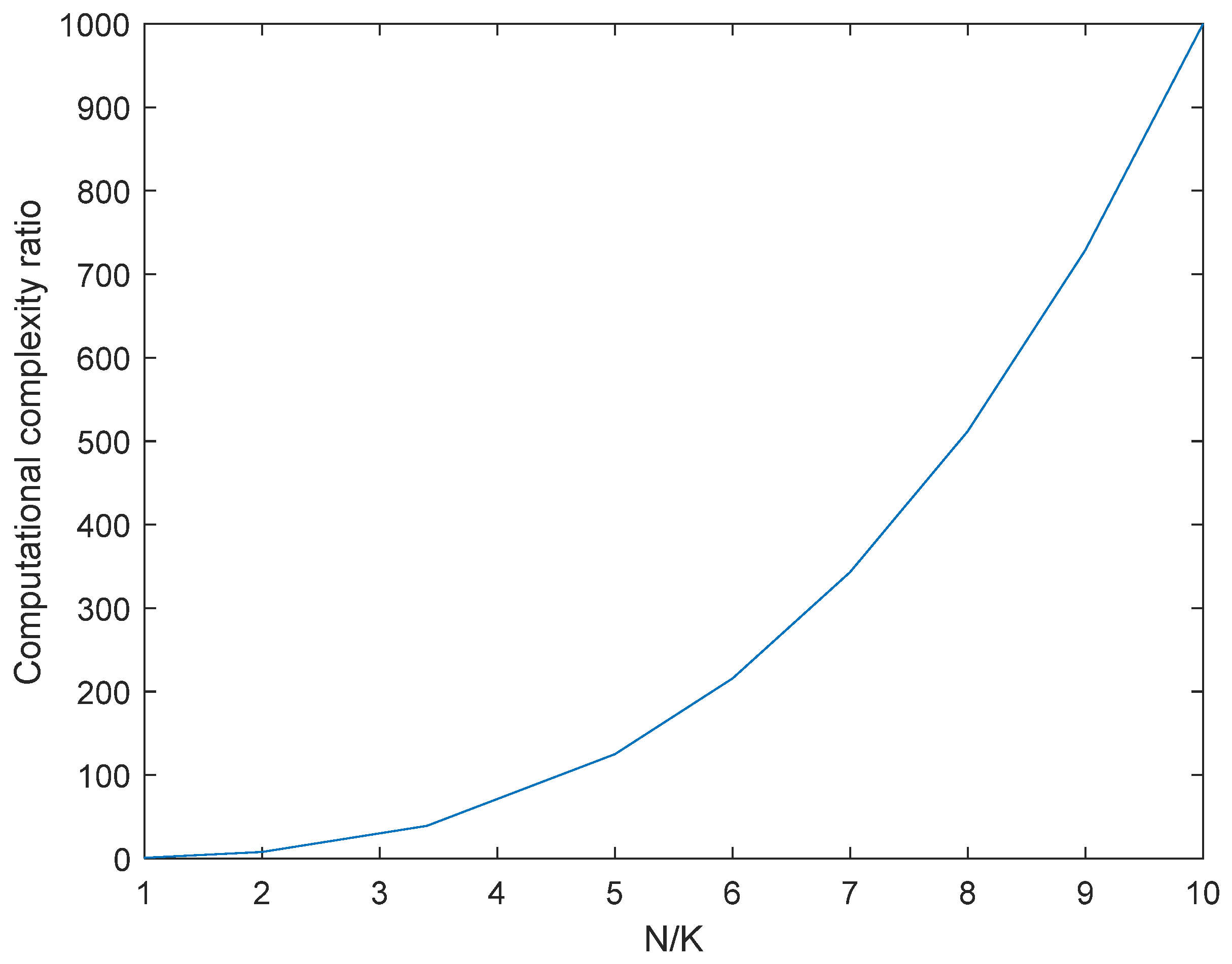
3.3. Computational Complexity Analysis
4. Results
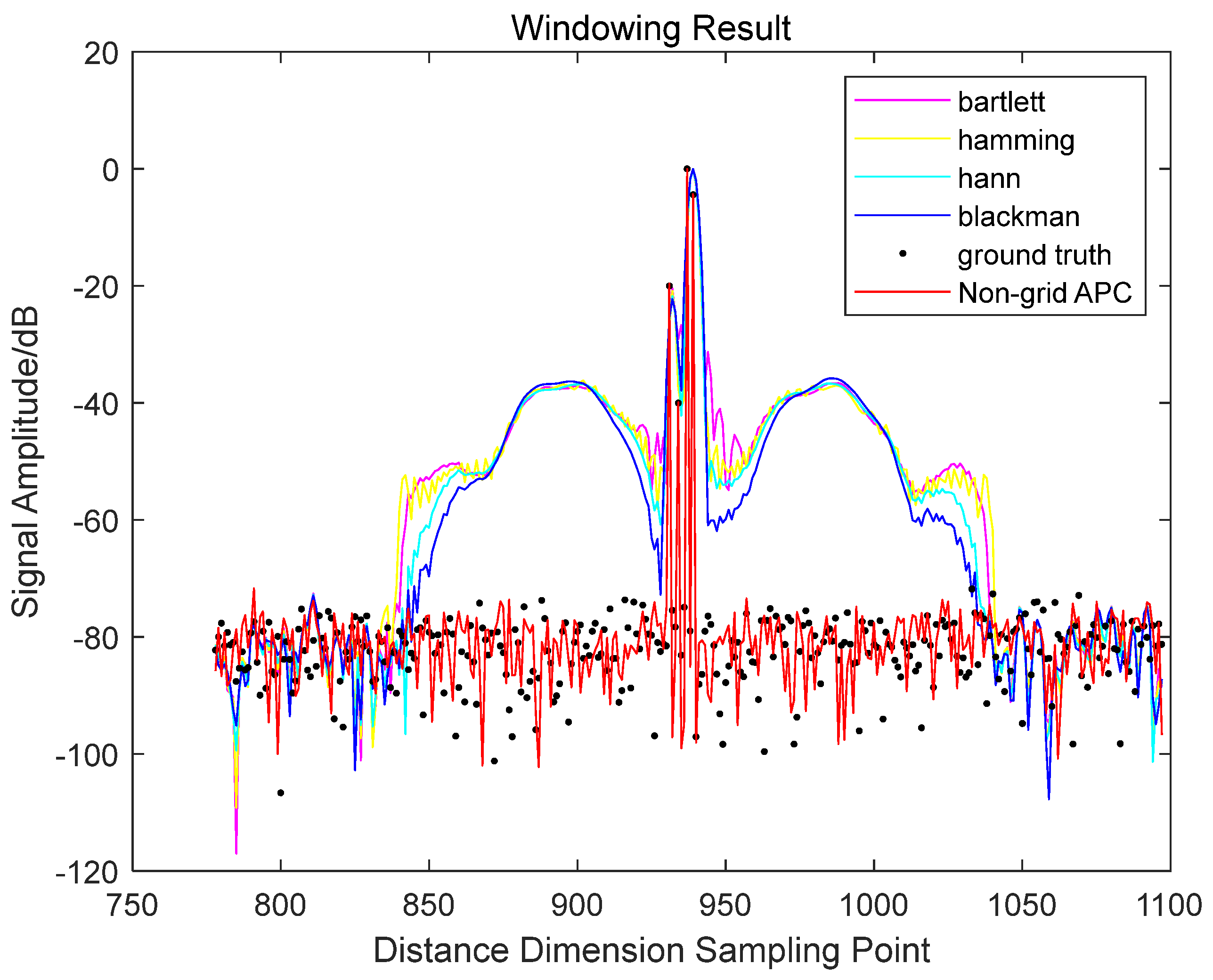
4.1. Simulation Result
4.2. Experimental Results of Tested Data
5. Conclusions
Author Contributions
Funding
Data Availability Statement
Conflicts of Interest
References
- Jiangbo, L.; Hongsheng, Y.; Dongbo, H.; Minh, N.D. Patch Match Filter: Efficient Edge-Aware Filtering Meets Randomized Search for Fast Correspondence Field Estimation. In Proceedings of the 2013 IEEE Conference on Computer Vision and Pattern Recognition, Portland, OR, USA, 23–28 June 2013; pp. 1854–1861. [Google Scholar]
- Gerlach, K.; Blunt, S.D.; Picciolo, M.L. Robust Adaptive Matched Filtering Using the FRACTA Algorithm. IEEE Trans. Aerosp. Electron. Syst. 2004, 40, 929–945. [Google Scholar] [CrossRef]
- Li, K.; Yuan, L. The FIR Window Function Design Based on Evolutionary Algorithm. In Proceedings of the 2011 International Conference on Mechatronic Science, Electric Engineering and Computer (MEC), Jilin, China, 19–22 August 2011; pp. 1797–1800. [Google Scholar]
- Wu, X.; Liu, K.; Luo, M.; Shen, Q. LMMSE Channel Estimation Algorithm Based on Delay Time-Domain Windowing in AF Cooperative Systems. In Proceedings of the 2011 6th International ICST Conference on Communications and Networking in China (CHINACOM), Harbin, China, 17–19 August 2011; pp. 760–764. [Google Scholar]
- Blinchikoff, H.J. Range Sidelobe Reduction for the Quadriphase Codes. IEEE Trans. Aerosp. Electron. Syst. 1996, 32, 668–675. [Google Scholar] [CrossRef]
- Fang, L.; Dong, D.; Boroyevich, D.; Mattavelli, P.; Wang, S. Improving High-Frequency Performance of an Input Common Mode EMI Filter Using an Impedance-Mismatching Filter. IEEE Trans. Power Electron. 2014, 29, 5111–5115. [Google Scholar]
- Rao, M.N. Design of Mismatched Filters for Long Binary Codes. In Proceedings of the 2008 IEEE Radar Conference, Rome, Italy, 26–30 May 2008; pp. 1–6. [Google Scholar]
- Bose, R. Lean CLEAN: Deconvolution Algorithm for Radar Imaging of Contiguous Targets. IEEE Trans. Aerosp. Electron. Syst. 2011, 47, 2190–2199. [Google Scholar] [CrossRef]
- Zrnic, B.; Zejak, A.; Petrovic, A.; Simic, I. Range Sidelobe Suppression for Pulse Compression Radars Utilizing Modified RLS Algorithm. In Proceedings of the 1998 IEEE International Symposium on Spread Spectrum Techniques and Applications, Sun City, South Africa, 2–4 September 1998; pp. 1008–1011. [Google Scholar]
- Yanming, L. Study on the Technology of Quadric Surface Extracting Base on Least Square Method. In Proceedings of the 2011 Second International Conference on Mechanic Automation and Control Engineering, Hohhot, China, 15–17 July 2011; pp. 5328–5331. [Google Scholar]
- Jin, E.S.; Liu, L.L.; Bo, Z.Q.; Klimek, A. Parameter Identification of the Transformer Winding Based on Least-Squares Method. In Proceedings of the 2008 IEEE Power and Energy Society General Meeting-Conversion and Delivery of Electrical Energy in the 21st Century, Pittsburgh, PA, USA, 20–24 July 2008; pp. 1–6. [Google Scholar]
- Blunt, S.D.; Gerlach, K. Adaptive Pulse Compression. In Proceedings of the 2004 IEEE International Radar Conference, Philadelphia, PA, USA, 18–21 December 2004; pp. 271–276. [Google Scholar]
- Blunt, S.D.; Gerlach, K. Adaptive Pulse Compression via MMSE Estimation. IEEE Trans. Aerosp. Electron. Syst. 2006, 42, 572–584. [Google Scholar] [CrossRef]
- Blunt, S.D.; Gerlach, K. A Novel Pulse Compression Scheme Based on Minimum Mean-Square Error Reiteration. In Proceedings of the 2003 Proceedings of the International Conference on Radar, Adelaide, SA, Australia, 3–5 September 2003; pp. 349–353. [Google Scholar]
- Blunt, S.D.; Smith, K.J.; Gerlach, K. Doppler-Compensated Adaptive Pulse Compression. In Proceedings of the 2006 IEEE Conference on Radar, Verona, NY, USA, 24–27 April 2006; pp. 1–6. [Google Scholar]
- Gerlach, K.; Blunt, S.D. Radar Pulse Compression Repair. IEEE Trans. Aerosp. Electron. Syst. 2007, 43, 1188–1195. [Google Scholar] [CrossRef]
- Blunt, S.D.; Higgins, T. Achieving Real-Time Efficiency for Adaptive Radar Pulse Compression. In Proceedings of the 2007 IEEE Radar Conference, Waltham, MA, USA, 17–20 April 2007; pp. 116–121. [Google Scholar]
- Blunt, S.D.; Higgins, T. Dimensionality Reduction Techniques for Efficient Adaptive Pulse Compression. IEEE Trans. Aerosp. Electron. Syst. 2010, 46, 349–362. [Google Scholar] [CrossRef]
- Henke, D.; Mccormick, P.; Blunt, S.D.; Higgins, T. Practical Aspects of Optimal Mismatch Filtering and Adaptive Pulse Compression for FM Waveforms. In Proceedings of the 2015 IEEE Radar Conference, Arlington, VA, USA, 10–15 May 2015; pp. 1149–1155. [Google Scholar]
- Henke, D. Robust Optimal and Adaptive Pulse Compression for FM Waveforms; University of Kansas: Kansas, MS, USA, 2015. [Google Scholar]
- VanTrees, H.L. Optimum Array Processing Part IV of Detection, Estimation and Modulation Theory; John Wiley and Sons Inc.: New York, NY, USA, 2002; pp. 513–518. [Google Scholar]
- Geng, Z.; Deng, H.; Himed, B. Adaptive Radar Beamforming for Interference Mitigation in Radar Wireless Spectrum Sharing. IEEE Signal Process. Lett. 2015, 22, 484–488. [Google Scholar] [CrossRef]
- Su, H.; Liu, H.; Shui, P.; Bao, Z. Adaptive Beamforming for Nonstationary HF Interference Cancellation in Skywave Over-the-Horizon Radar. IEEE Trans. Aerosp. Electron. Syst. 2013, 49, 312–324. [Google Scholar] [CrossRef]
- Blunt, S.D.; Gerlach, K. Adaptive Pulse Compression Repair Processing. In Proceedings of the 2005 IEEE International Radar Conference, Arlington, VA, USA, 29 July 2005; pp. 519–523. [Google Scholar]
- Shackelford, A.K.; De Graaf, J.; Talapatra, S.; Blunt, S.D.; Gerlach, K. Adaptive Pulse Compression: Preliminary Experimental Measurements. In Proceedings of the 2007 IEEE Radar Conference, Waltham, MA, USA, 17–20 April 2007; pp. 234–237. [Google Scholar]
- Baghel, V.; Panda, A.; Panda, G. An Efficient Hybrid Adaptive Pulse Compression Approach to Radar Detection. In Proceedings of the 2013 International Conference on Signal Processing and Communication, Noida, India, 12–14 December 2013; pp. 335–339. [Google Scholar]
- Qianrong, L.; Xiji, W.; Zhicheng, W.; Xiaochao, M.; Na, Y. Robust Adaptive Pulse Compression Under Encode-Decoder Network for Synthetic Aperture Radar. In Proceedings of the 2021 Asia-Pacific Conference on Synthetic Aperture Radar (APSAR), Bali, Indonesia, 1–5 November 2021; pp. 1–5. [Google Scholar]
- Qianrong, L.; Wenming, T.; Qingqing, L.; Bingqi, Z.; Ke, D.; Xiangzhen, Y. Robust Adaptive Pulse Compression for Synthetic Aperture Radar. In Proceedings of the 2021 China International SAR Symposium (CISS), Shanghai, China, 3–5 November 2021; pp. 1–6. [Google Scholar]
- Higgins, T.; Blunt, S.D.; Gerlach, K. Gain-Constrained Adaptive Pulse Compression via An MVDR Framework. In Proceedings of the 2009 IEEE Radar Conference, Pasadena, CA, USA, 12–16 October 2009; pp. 1–6. [Google Scholar]
- Akdemir, Ş.B.; Candan, Ç. Study of Angle of Arrival Estimation Performance of MVDR and Capon Methods under Intermittent Interference. In Proceedings of the 2018 Signal Processing and Communications Applications Conference (SIU), Izmir, Turkey, 2–5 May 2018; pp. 1–4. [Google Scholar]


|
|
| Steps | Echo APC | Match the Filtered Non-Grid APC |
|---|---|---|
| matrix construction | ||
| Filter weight vector | ||
| estimation |
| Algorithm | Computational Complexity |
|---|---|
| APC algorithm based on echo | |
| FAPC | |
| LCMV-APC | |
| Non-grid APC |
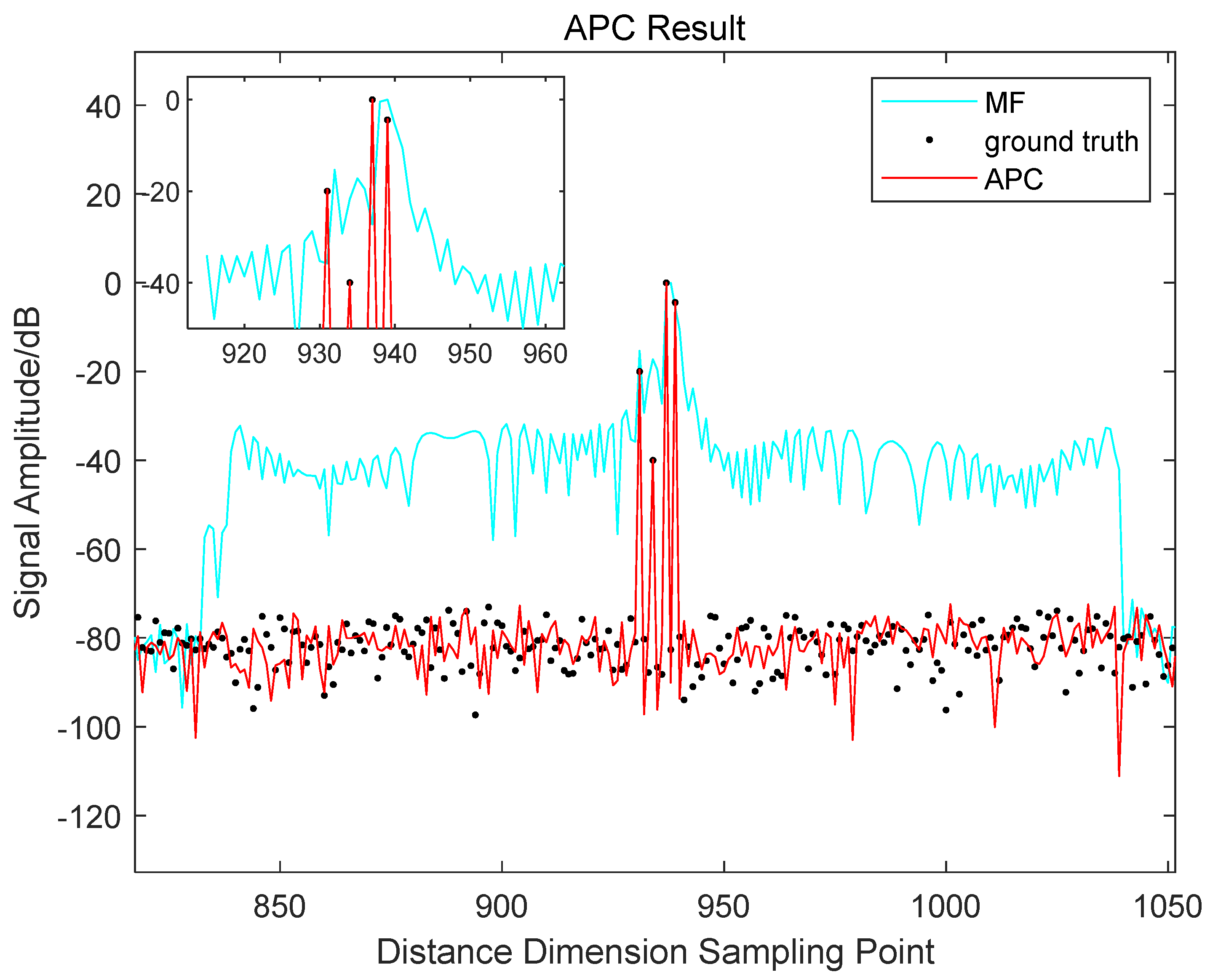
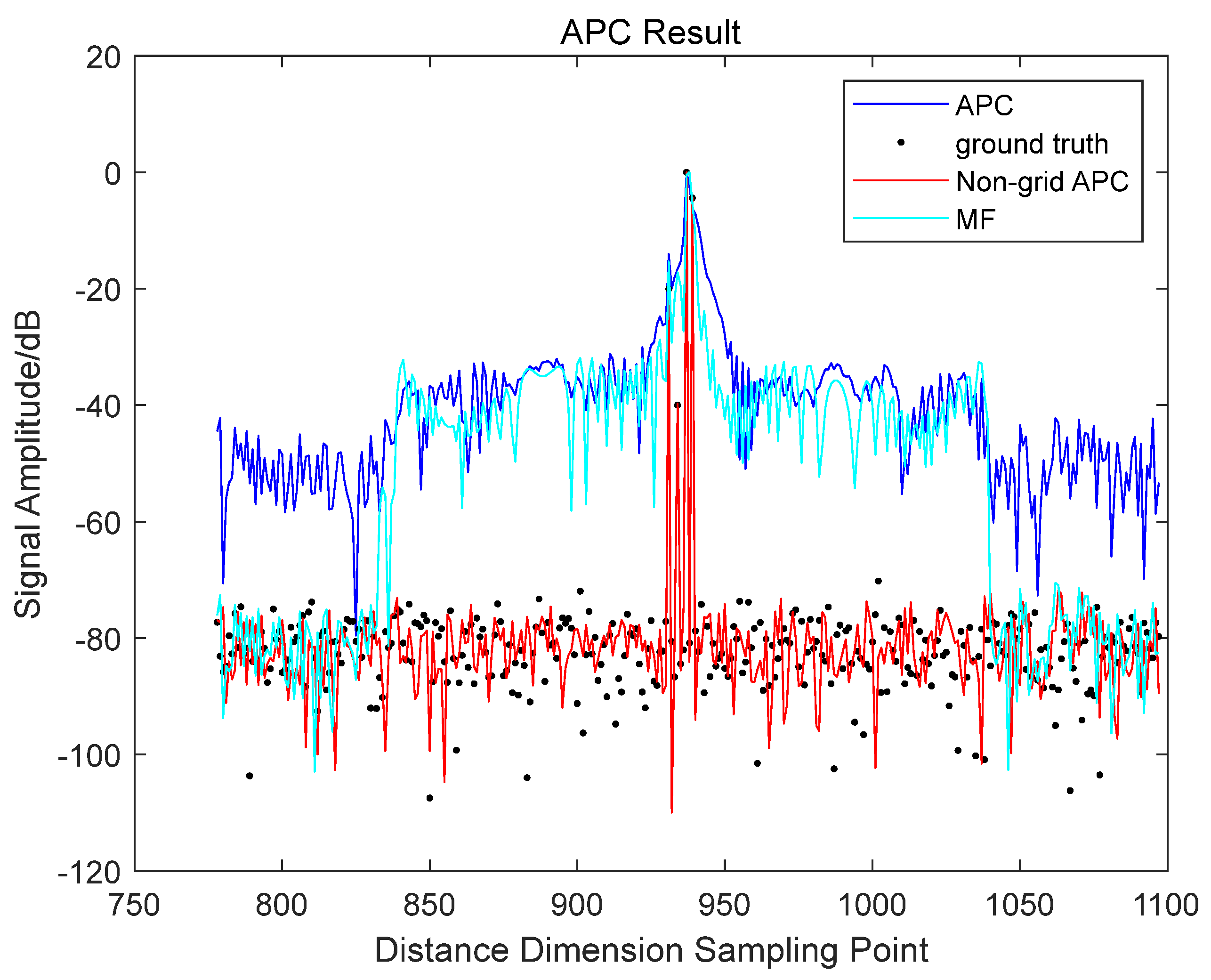
| Targets | The Index of Sampling Points of the Target Distance Dimension | Target SNR/dB |
|---|---|---|
| 1 | 931.09 | 20 |
| 2 | 934.18 | 40 |
| 3 | 947.42 | 80 |
| 4 | 939.11 | 75.56 |
| Targets | The Index of Sampling Points of the Target Distance Dimension | Ground Truth Amplitude/dB | Non-Grid APC Amplitude/dB |
|---|---|---|---|
| 1 | 931.09 | −20 | −19.65 |
| 2 | 934.18 | −40 | −39.83 |
| 3 | 947.42 | 0 | 0 |
| 4 | 939.11 | −4.43 | −4.31 |
Disclaimer/Publisher’s Note: The statements, opinions and data contained in all publications are solely those of the individual author(s) and contributor(s) and not of MDPI and/or the editor(s). MDPI and/or the editor(s) disclaim responsibility for any injury to people or property resulting from any ideas, methods, instructions or products referred to in the content. |
© 2023 by the authors. Licensee MDPI, Basel, Switzerland. This article is an open access article distributed under the terms and conditions of the Creative Commons Attribution (CC BY) license (https://creativecommons.org/licenses/by/4.0/).
Share and Cite
Xu, J.; Zhang, Y.; Zhang, J.; Chen, J. Range Sidelobe Iterative Suppression Algorithm for Extended Target with Non-Grid Multiple Scattering Points. Remote Sens. 2023, 15, 4811. https://doi.org/10.3390/rs15194811
Xu J, Zhang Y, Zhang J, Chen J. Range Sidelobe Iterative Suppression Algorithm for Extended Target with Non-Grid Multiple Scattering Points. Remote Sensing. 2023; 15(19):4811. https://doi.org/10.3390/rs15194811
Chicago/Turabian StyleXu, Jing, Yanan Zhang, Jindong Zhang, and Jiarui Chen. 2023. "Range Sidelobe Iterative Suppression Algorithm for Extended Target with Non-Grid Multiple Scattering Points" Remote Sensing 15, no. 19: 4811. https://doi.org/10.3390/rs15194811
APA StyleXu, J., Zhang, Y., Zhang, J., & Chen, J. (2023). Range Sidelobe Iterative Suppression Algorithm for Extended Target with Non-Grid Multiple Scattering Points. Remote Sensing, 15(19), 4811. https://doi.org/10.3390/rs15194811