Article

Evaluation of Simulated CO2 Point Source Plumes from High-Resolution Atmospheric Transport Model

1
Anhui Institute of Optics and Fine Mechanics, Hefei Institute of Physical Science, Chinese Academy of Sciences, Hefei 230031, China
2
Science Island Branch, University of Science and Technology of China, Hefei 230026, China
3
Key Laboratory of General Optical Calibration and Characterization Technology, Hefei Institutes of Physical Science, Chinese Academy of Sciences, Hefei 230031, China
*
Author to whom correspondence should be addressed.
Remote Sens. 2023, 15(18), 4518; https://doi.org/10.3390/rs15184518
Submission received: 10 August 2023 / Revised: 11 September 2023 / Accepted: 13 September 2023 / Published: 14 September 2023
(This article belongs to the Special Issue Remote Sensing of Carbon Fluxes and Stocks II)

Abstract

:
Coal-fired power plants, as major anthropogenic CO2 emission sources, constitute one of the largest contributors to global greenhouse gas emissions. Accurately calculating the dispersion process of CO2 emissions from these point sources is crucial, as it will aid in quantifying CO2 emissions using remote sensing measurements. Employing the Lagrangian Particle Dispersion Theory Model (LPDTM), our study involves modeling CO2 diffusion from point sources. Firstly, we incorporated high-resolution DEM (Digital Elevation Model) and artificial building elements obtained through the Adaptive Deep Learning Location Matching Method, which is involved in CO2 simulation. The accuracy of the results was verified using meteorological stations and aircraft measurements. Additionally, we quantitatively analyzed the influence of terrain and artificial building characteristics on high spatial resolution atmospheric CO2 diffusion simulations, revealing the significance of surface characteristics in dispersion modeling. To validate the accuracy of the LPDTM in high-resolution CO2 diffusion simulation, a comparative experiment was conducted at a power plant in Yangzhou, Jiangsu Province, China. The simulated result was compared with observation from aerial flights, yielding the R2 (Correlation Coefficient) of 0.76, the RMSE (Root Mean Square Error) of 0.267 ppm, and the MAE (Mean Absolute Error) of 0.2315 ppm for the comparison of 73 pixels where the plume intersected with flight trajectories. The findings demonstrate a high level of consistency between the modeled CO2 point source plume morphology and concentration quantification and the actual observed outcomes. This study carried out a quantitative assessment of the influence of surface features on high-resolution atmospheric CO2 point source diffusion simulations, resulting in an enhanced accuracy of the simulated CO2 concentration field. It offers essential technological and theoretical foundations for the accurate quantification of anthropogenic CO2 emissions using top-down approaches.

1. Introduction

Atmospheric CO2, as the primary anthropogenic greenhouse gas, exhibits the highest concentration and emissions in the atmosphere, constituting about 76% of the total greenhouse gas emissions. It serves as a major driving force behind global climate change [1]. According to the 2018 compilation of sectoral greenhouse gas emissions, approximately 34% of global anthropogenic CO2 emissions originate from the energy sector, while 24% come from the industrial sector. These emissions in these sectors mainly result from power plants and industrial combustion facilities [2,3]. Effectively dealing with the environmental issues resulting from major emitting industries is crucial for achieving sustainable development and mitigating global climate change. Therefore, accurately quantifying CO2 point source emissions from enterprises will directly impact the quality and reliability of greenhouse gas emission inventories. It will also contribute to a better understanding of human activities’ impact on the climate and provide scientific evidence for the development of effective CO2 emission reduction strategies at the national and regional levels.
Satellite remote sensing has become a principal technique for acquiring global atmospheric CO2 concentration data. Currently, Japan, the United States, and China have each launched satellites equipped with the capability to observe atmospheric CO2, making significant contributions to the global scientific community [4,5,6,7,8]. During the column-averaged dry-air mole fractions of CO2 (XCO2) retrieval, the accuracy and reliability of the results are affected by factors such as the spectrometer’s resolution and signal-to-noise ratio, as well as atmospheric aerosols, clouds, and surface reflection characteristics [9,10]. Incorporating known a priori knowledge can improve the precision and reliability of the retrieval results. Nevertheless, improper initialization can lead to inaccurate retrieval results, or the iterative algorithm failing to converge [11]. Laughner et al. [12] demonstrated that the prior CO2 profile in the GGG (applied to Bruker 125HR in Total Column Observing Network) retrieval algorithm has a significant impact on the retrieval results. Compared to the AirCore observation profile, based on the newly constructed GGG2020 prior profile relative to the GGG2014 version, participating in the TCCON gas retrieval calculation, the XCO2 retrieval accuracy has achieved a 54.5% improvement. Achieving a 1% increase in XCO2 retrieval accuracy requires that the initial atmospheric CO2 data accuracy be at least 2% higher [13]. With the continuous improvement of atmospheric CO2 satellite observation technology, greenhouse gas monitoring satellites are progressively contributing to global carbon inventory verification, carbon flux monitoring, and the precise quantification of anthropogenic carbon emissions. To fulfill these objectives, satellite payload systems are required to provide wide-swath imaging, high-resolution, and high-precision observation and retrieval capabilities, including the ability to provide surface-distributed initial values. Landgraf et al. [14] and Malina et al. [15] achieved a 40~45% improvement in retrieval accuracy by incorporating detailed emission information and diffusion distribution related to CH4 emission sources, highlighting the critical role and significance of surface-distributed initial values. Thus, adequately considering the spatial distribution of emission sources, such as coal-fired power plants and cement factories, during the retrieval process contributes to enhancing the accuracy of remote sensing greenhouse gas retrievals. The availability of surface-distributed initial values depends on CO2 emission simulations.
The atmospheric diffusion model is a physical and mathematical model used to study the transportation, diffusion, and deposition processes of atmospheric emissions, simulating the atmospheric environment and estimating changes in the concentration of pollutants during propagation. Considering the fluid reference system, the Lagrangian and Eulerian reference frames are two commonly used methods to describe fluid movement and are widely applied in box models, Gaussian plume models, and puff models. Holmes and Morawska [16] compared various types of box models, Gaussian models, Lagrangian, and Eulerian in the atmospheric aerosol particle diffusion results, pointing out that each model has its unique application scenario, depending on the scale of the study, the complexity of the environment, and the required gas pollutant concentration parameters. Box models such as AURORA (Air Quality Modelling in Urban Regions using an Optimal Resolution Approach) and CPB (Canyon Plume Box) are suitable for simplified scenarios, while more complex CFD (Computational Fluid Dynamics) models such as ARIA Local and MISKAM (Microscale flow and dispersion model) are better suited for intricate environments. Some models also integrate aerosol dynamics to simulate particle behavior more accurately in the atmosphere. In general, selecting an appropriate model depends on the specific research requirements and conditions. Oettl et al. [17] and Stohl et al. [18], by comparing Eulerian and Lagrangian models, found that the Eulerian model is more suitable for simulating wind fields, while the Lagrangian model is more suited for tracing the diffusion and trajectory of atmospheric pollutants. This distinction is closely related to the spatial reference frame each uses, with the Eulerian model using a fixed frame to describe fluid properties, focusing on fluid changes at specific spatial points, while the Lagrangian model employs a moving frame to track changes in fluid particle properties over time. In recent years, due to the advancement of carbon assessments in various countries mentioned in the United Nations Framework Convention on Climate Change (UNFCCC), research on atmospheric greenhouse gas CO2 diffusion simulations has been on the rise. Models such as GEOS-Chem (the Goddard Earth Observing System with chemistry), WRF-Chem (the Weather Research and Forecasting model coupled with Chemistry), FLEXPART (FLEXible PARTicle dispersion model), STILT (the Stochastic Time-Inverted Lagrangian Transport model), LES (Large-Eddy Simulation), HYSPLIT (The Hybrid Single-Particle Lagrangian Integrated Trajectory model), and CALPUFF (California Puff Model) are extensively applied at global, regional, and factory scales, with varying capabilities and scopes [19,20,21,22,23,24,25]. Callewaert et al. [20], using the WRF-Chem model, analyzed atmospheric observation data on Réunion Island in the Indian Ocean, delving deeply into the factors influencing observed CO2, CH4, and CO concentration changes in the region. WRF-Chem accurately simulated local meteorological data, especially temperature data, and the apparent CO2 diurnal cycle observed in Saint-Denis was mainly influenced by local assumed emissions, boundary layer dynamics, and nighttime wind speed patterns, with WRF-Chem’s overestimation of wind speeds leading to an underestimation of nighttime CO2 accumulation. Hu et al. [22], applying WRF-STILT to simulate CO2 concentrations over cornfields in the U.S. in 2008, found that the model captured CO2′s strong seasonality and diurnal variations. Comparing simulation results with the EDGAR emission inventory and Carbon Tracker NEE flux data, they identified WRF-STILT’s overestimation of fossil fuel emissions and underestimation of NEE. Brunner et al. [26] conducted a comparative analysis of six atmospheric CO2 transport models. Their findings revealed that Large Eddy Simulation (LES), mesoscale numerical weather prediction (NWP), and Lagrangian Particle Dispersion Model (LPDM) can simulate CO2 at various spatial resolutions ranging from >50 km to 0.2–2 km. While LES and NWP demonstrated good consistency in kilometer-level simulations, their agreement with CO2M simulation data deteriorated at meter-level resolutions. In contrast, LPDM showed higher agreement with simulated CO2M data, particularly for higher spatial resolutions, and exhibited lower emission intensity errors compared to the other five models, underscoring the necessity of careful model selection in the simulation process. Choosing the appropriate atmospheric CO2 diffusion model will contribute to higher precision in CO2 simulations and fully harness the model’s capabilities. Among them, the Lagrangian model is more suitable for simulations under high-resolution conditions.
Atmospheric CO2 transport models can be used to simulate and quantify the dispersion patterns of CO2 emissions from enterprises. However, due to factors such as wind variability, emission fluctuations, or other unpredictable elements, there can be uncertainties in the simulation results. Cusworth et al. [27] and Guanter et al. [28] conducted CO2 emission measurements of 17 thermal power plants using PRISMA (PRecursore IperSpettrale della Missione Applicativa) airborne observations, achieving a spatial resolution of 30 m. Through quantitative CO2 emission estimation, they obtained an average discrepancy in carbon emission intensity estimation ranging from 21% to 75% for these power plants. The analysis revealed that the discrepancies in estimation primarily stem from wind direction, wind speed, prior emission factors, and CO2 dispersion models. The experimental results indicated that the average error introduced by CO2 diffusion and transport itself is 21%. Wind direction, wind speed, prior emission factors, terrain, and surface characteristics are closely interrelated with atmospheric CO2 diffusion simulations. These factors exert a considerable influence on the precision of model simulation results. Based on European CO2M (Copernicus Anthropogenic CO2 Monitoring) mission, Zheng et al. [29] and O’Brien et al. [30] used WRF-Chem to perform spatial distribution simulations of CO2 and CH4. They compared the simulation results with observations from the GOSAT (Greenhouse gases Observing SATellite) and OCO-2 (Orbiting Carbon Observatory-2) satellites and found that wind speed errors are directly related to the differences in CO2 and CH4 simulation results. Furthermore, their quantitative investigation of the influence of wind direction and speed on the diffusion process indicated that a 1% wind speed bias, when the wind speed exceeds 10 m/s, can cause a 2.8% difference in emission intensity estimation. Conversely, when the actual wind speed is below 5 m/s, a 1% wind speed bias results in a 0.7% emission estimation discrepancy, underscoring the particular importance of wind speed data accuracy for simulation precision. Under high spatial resolution conditions, the variations in terrain elevations and surface architecture introduce complexity into the surface morphology, thereby altering the spatial distribution of the wind field [31,32]. As this changed wind field distribution serves as the driving force for dispersion, it inevitably leads to variations in the spatial distribution and CO2 intensity. Consequently, this impacts the estimation of CO2 plume distribution and further influences its utility as an initial value or in other carbon emission estimation activities during remote sensing retrievals. The complexity of surface features in high spatial resolution scenarios necessitates the use of simplified methods in current CO2 diffusion simulations, inevitably resulting in a decline in simulation accuracy. Considering the growing demand for carbon emission estimation and the technological trend towards high-resolution approaches, a comprehensive consideration of surface effects and an enhancement in simulation accuracy become indispensable prerequisites for future remote sensing and other monitoring technologies.
With the increasing demand for higher precision XCO2 retrieval and accurate estimation of carbon dioxide emissions from industrial point sources, driven by the new generation of greenhouse gas detection satellites, this study explores high spatial resolution simulation of atmospheric CO2 diffusion. Considering the significant role of wind fields as reflected in the application example and considering the influence of surface features on the wind field, we based our research on the Lagrangian particle dispersion theory. We incorporated high-resolution topographic and urban artificial buildings feature data using a deep learning-based adaptive location matching algorithm. Our primary focus was on exploring the relationship between surface features and wind fields under high spatial resolution conditions and their impact on atmospheric CO2 diffusion. To validate the precision of the location matching method and high spatial resolution simulation of atmospheric CO2 emissions, this research conducted experimental observations using ground-based measurements from the photoacoustic spectroscopy multi-gas analyzer (Gasera One, Duke technology Co., Ltd., Wuhan, China) at Anhui Wanneng Power Plant in Hefei, Anhui Province, China, and airborne observations from SHIS (Spatial Heterodyne Imaging Spectroscopy) at China Huadian Power Plant in Yangzhou, Jiangsu Province, China. These experiments served to further assess the accuracy of the location matching method and model simulations.

2. The Lagrangian Particle Dispersion Model

Gas emissions involve the dispersion of emitted substances in the atmosphere, considering both temporal and spatial aspects. The diffusion process of emissions is influenced by multiple factors, including atmospheric environmental conditions, the properties of the emitted substances, and the terrain and topography. Currently, the commonly utilized models to understand atmospheric dispersion patterns encompass the Lagrangian model, Gaussian model, three-dimensional numerical simulation model, and box model [33,34,35,36]. The Lagrangian model, as an atmospheric dispersion model, is based on the Lagrangian method, which involves simulating and tracking the trajectories of gas particles to calculate their time and spatial probability distributions for predicting gas dispersion and transport behavior. It possesses unique features, such as the ability to simulate concentration variations in non-uniform and non-steady meteorological conditions, and is not constrained by assumptions of homogeneity, steadiness, or terrain limitations. The model can handle both advection and turbulence effects, accurately describing the fine variations in emission processes. In this study, which primarily focuses on high spatial resolution CO2 point source diffusion patterns, the Lagrangian model is deemed to be highly suitable as a simulation tool [37].
The Lagrangian atmospheric dispersion model is based on several fundamental hypotheses. Firstly, the model assumes that the atmosphere consists of gases composed of countless tiny particles that adhere to Newton’s laws of motion. Secondly, it postulates that the flow and mixing in the atmosphere are predominantly driven by turbulent vortices. Lastly, the model assumes that the CO2 transport in the atmosphere is influenced by various factors, such as turbulence, atmospheric stability, and surface characteristics. Mathematically, the model represents the motion of gas molecules using a system of differential equations and utilizes their solutions to calculate the positions and velocities of gas particles. While performing calculations, the model considers elements such as wind speed, wind direction, terrain, land use types, and other factors to predict the behavior of gas dispersion and transport in the atmosphere [38,39].
In the Lagrangian atmospheric dispersion model, the basic concentration equation for each receptor point is given by:
C = Q 2 π σ x σ y g exp ( d a 2 2 σ x 2 ) exp ( d c 2 2 σ y 2 )
g = 2 σ z 2 π n = exp [ ( H e + 2 n h ) 2 2 σ z 2 ]
where C represents ground-level gas concentration in units of g / m 2 , Q stands for the source emission rate, σ x , σ y , and σ z are the dispersion coefficients, d a is the downwind distance, d c is the crosswind distance, H e denotes the effective height, h represents the mixing layer height, and g is the Gaussian plume vertical term, addressing multiple reflections between the mixing layer and the ground. Furthermore, during the dispersion simulation, it is necessary to consider both the horizontal and vertical dispersion coefficients, i.e., σ y and σ z , which are given by:
σ y n 2 ( Δ ξ y ) = σ y t 2 ( Δ ξ y n + Δ ξ y ) + σ y s 2 + σ y b 2
σ z n 2 ( Δ ξ z ) = σ z t 2 ( Δ ξ z n + Δ ξ z ) + σ z b 2
where ξ y n and Δ ξ z n represent the virtual source parameters when Δ ξ = 0 , σ y n and σ z n are the horizontal and vertical dispersion coefficients at a specified location during atmospheric dispersion process, σ y t and σ z t are the dispersion coefficients formed by atmospheric turbulence represented by σ y and σ z , σ y b and σ z b are the horizontal and vertical dispersion components generated by buoyancy-included lift during the dispersion process, and σ y s represents the lateral dispersion component produced by lateral diffusion from the surface source.
The Lagrangian atmospheric dispersion model requires the simulation of numerous gas particle trajectories, and it does not restrict the distribution of particle positions to grid cells. Consequently, it can capture fine distributions that are beyond the capabilities of grid-based transport models. When computational resources are abundant, the model can achieve high spatial resolution for simulating the atmospheric CO2 dispersion. Additionally, it can simulate the non-uniform CO2 spatial distribution, including both horizontal and vertical diffusion, and can produce dispersion results for CO2 plumes within intermediate scales, ranging from a few dozen to several hundred kilometers [40]. Furthermore, the model considers non-steady-state conditions, including low wind speeds, circulation, topography, and coastal effects, and provides accurate simulation parameters.
The complexity of the underlying surface has always been one of the main challenges in numerical simulations. Mesoscale models often use terrain-following coordinates to describe complex terrain. However, most mesoscale models have limited capabilities in handling complex terrain, especially when the terrain is too steep (e.g., slope greater than 60°), resulting in difficulties in achieving stable and convergent numerical solutions [41,42]. In urban areas, the complexity of the underlying surface is even more pronounced due to the presence of artificial buildings, which adds further intricacies to the geometric characteristics of the underlying surface.
The Lagrangian atmospheric dispersion model based on complex terrain diffusion model utilizes grid nesting to simulate the impact of small-scale complex terrain on the ground-level CO2 concentrations [43,44]. It mainly involves the following three steps:
  • Adjusting the wind field based on large-scale terrain.
  • Precisely simulating the interaction between CO2 plume and terrain under conditions where the large-scale wind field has minimal impact.
  • Simplifying the interaction between CO2 plume and terrain (including both large and small-scale terrain features). This involves employing streamline-layering estimation for plume deviation caused by complex subgrid-scale terrain, using plume trajectory coefficient adjustment method and stress-adjustment method to simplify parameter adjustments for plume height changes due to terrain, plume collision with mountains, and the effect of increased diffusion coefficients.
The ground-level concentration (GLC) at the mountain receptor points above streamline-layering height ( H d ) is related as follows:
G L C H = Q t 2 t 1 F y ( t R ) F z ( t R ) 4 π μ σ z e σ y e { e r f ( t 2 t 1 2 σ y e / μ ) e r f ( t 1 t R 2 σ y e / μ ) }
where Q represents the total mass of emissions in the CO2 plume from time t 1 to t 2 , t R is the diffusion time from the source to the receptor point, F y and F z are the vertical and horizontal dispersion functions, respectively, μ is the mean wind speed at the plume center height, and σ z e and σ y e are the vertical and horizontal dispersion coefficients influenced by the complex terrain at time t R .
The concentration at the receptor points below the directional-layering height ( H d ) is given by the following relationship:
G L C L = Q t 2 t 1 F y ( t R ) F z ( t R ) 4 π μ σ z σ y { e r f ( t 2 t R 2 σ y / μ ) e r f ( t 1 t R 2 σ y / μ ) }
where the vertical ( σ z ) and horizontal ( σ y ) dispersion coefficients at time t R are different from the formula above H d . Below H d , the variation in dispersion rates caused by the terrain is relatively small.
Surface characteristics play an important role in the simulation of atmospheric CO2 dispersion. Variations in terrain height and the distribution of artificial building directly influence the airflow patterns, thus significantly impacting CO2 dispersion. Accurately assessing the sensitivity of surface characteristics is of great significance for optimizing model parameterization, improving prediction accuracy, and gaining a deeper understanding of CO2 transport mechanisms. Therefore, this study combines the capabilities of the Lagrangian particle dispersion theory for high spatial resolution and complex surface feature simulations. Through parameter sensitivity analysis and perturbation methods, we quantify the contributions of surface characteristics in the model and further elucidate their importance in the simulation.

3. Sensitivity Analysis of Surface Characteristics for CO2 Dispersion

In the process of atmospheric CO2 dispersion, it is primarily influenced by factors such as wind speed, wind direction, and surface characteristics [45], where surface characteristics mainly include variations in terrain features and changes in land use types. Surface undulations contribute to the alterations in driving wind speed and wind direction, jointly affecting the CO2 transport and distribution in the atmosphere. While land use types alter CO2 distribution through source-sink effects [46], they can be neglected in this study, which focuses on short-term processes of CO2 point source dispersion.
The characteristics of surface undulations vary under different spatial resolutions. Figure 1 illustrates the changes in the digital elevation model (DEM) of the surface under different spatial resolutions. The data were obtained by analyzing six different resolutions, including 1 km, 500 m, 100 m, 50 m, 30 m, and 10 m, along the blue line in Figure 1a. It is evident that as the spatial resolution increases, the differences in surface undulations become more pronounced, with neighboring pixels exhibiting larger variations in surface elevations. This significant variation in surface elevations at higher spatial resolutions indicates a stronger influence of surface undulations on wind speed and wind direction. On the other hand, at lower resolutions, the impact of terrain is less prominent due to the region’s average effect.
In the high-resolution Lagrangian particle dispersion model, the DEM data were used as the sole input parameter for surface elevation variation. However, since the DEM data only represent natural surface elevation changes and does not account for man-made structures above the surface, its ability to capture the influence of surface roughness, especially in urban areas, is limited. Figure 2a displays the 10 m DEM data for the Paris region in France, with its topography being represented by the green line in Figure 2c. Figure 2b shows the building distribution in the same region, represented by the blue line in Figure 2c. It can be observed that under high spatial resolution conditions, the influence of buildings on surface roughness is more pronounced, leading to a larger impact on wind speed and direction within the region. Therefore, in this study, since considering topography, particular emphasis is placed on incorporating information on artificial buildings into the Lagrangian particle dispersion model through the surface. This ensures the accuracy of both urban surface wind fields and atmospheric CO2 diffusion simulations.
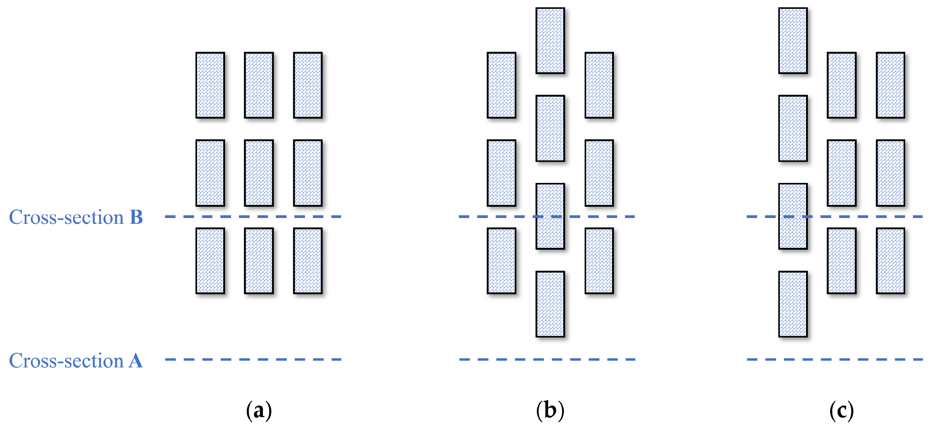
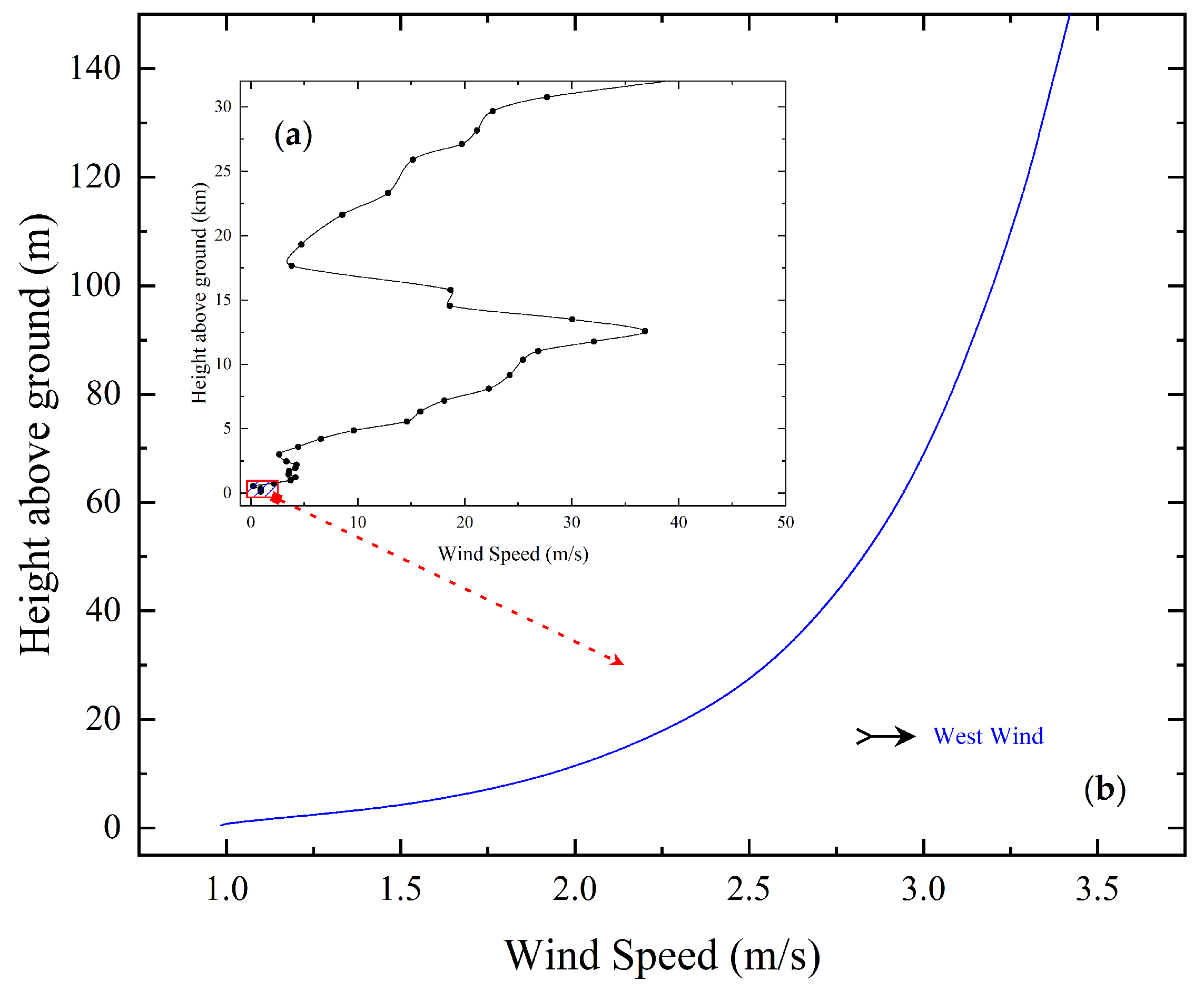
For studying the influence of artificial buildings on the wind field, three typical distribution patterns were designed in this study, as shown in Figure 3a–c. All three building layouts are designed as multi-story buildings with dimensions of 40 m × 20 m × 20 m (length × width × height). The street canyon width and spacing between adjacent buildings are set at 20 m. Figure 3a corresponds to a regular 3 × 3 arrangement of buildings, while layouts Figure 3b,c represent the second-row obstruction and the first-row obstruction, respectively, aiming to analyze CO2 diffusion paths encountering direct building obstructions or experiencing secondary strong obstructions after entering the area. With a westerly wind direction and a surface wind speed of 2 m/s, the vertical wind speed profiles are derived from the typical curves provided by the National Centers for Environmental Information (NOAA) Profiler Network (NPN) wind profile dataset, as presented in Figure 4. For visualizing the wind field and CO2 diffusion distribution in the three layout scenarios, we have selected two cross-sections (profiles), labeled as A and B. Cross-section A corresponds to the position below the building layout, while cross-section B is placed in the middle of the building arrangement. Furthermore, we have utilized a top-down perspective and selected three height levels at 5 m, 15 m, and 25 m.
In Figure 5, the airflow velocity vector maps for the three layout scenarios (a–c) in Figure 3 are displayed, observed from profiles A and B, presented in the upper and lower rows, respectively. The surface elevation variation has a profound impact on wind speed and direction, especially near buildings, leading to the formation of airflow vortices. The simulation results reveal that the centers of these vortices exhibit lower flow velocities, with an average wind speed below 1 m/s. Overall, the influence of buildings on the wind field varies with height. With increased height, structures have less impact on the wind field, especially outside the height of the buildings. However, within the height range of the buildings, the wind field is significantly affected. In Figure 5, a noticeable difference in wind speed and direction within the wind field can be observed when comparing three layouts (a–c) at the same height, primarily attributed to the varying obstruction patterns. The wind field, which acts as the driving force for CO2 dispersion, shows significant changes when impacted by the undulating terrain. Therefore, to achieve high-precision CO2 diffusion simulation, accurate representation of the surface characteristics within the height range of buildings is essential.
From a top-down perspective, Figure 6 displays the airflow velocity variations at three heights: 5 m, 15 m, and 25 m. In the overhead perspectives (Figure 6(a1,b1,c1) to 5 m and Figure 6(a2,b2,c2) to 15 m) at heights below the 20 m buildings, significant fluctuations in wind speed and direction occur around the buildings. As one moves away from the buildings, the airflow gradually converges, and the wind direction gradually diverges. The simulation results show that there is a significant decrease in wind speed behind the building obstacles, with an average wind speed below 1 m/s. At different heights, the converged airflow exhibits varying initial wind speeds, reaching a maximum of 2.4 m/s at 5 m height and 3.0 m/s at 15 m height. When the height is increased to 25 m in Figure 6(a3,b3,c3), which is above the designated height of the 20 m buildings, the wind field is no longer directly influenced by the buildings. However, turbulence occurs near the top of the buildings due to the updraft caused by the obstruction. The wind field variations at heights of 5 m, 15 m, and 25 m show that buildings have a significant impact on the wind field, both horizontally and vertically. Moving away from the buildings, the wind speed and directions gradually converge and become more consistent.
Under the high-resolution modeling setting, the simulations clearly depict the distinct effects of terrain and artificial building variations, causing substantial changes in the spatial distribution of wind direction and speed within the airflow. The variations in wind field, as the dominant force driving CO2 dispersion, will directly affect the changes in the spatial distribution of CO2 plumes. Therefore, in the actual simulation process, providing high-precision surface height feature datasets becomes a crucial technical aspect for high-resolution CO2 point source dispersion modeling. However, due to disparities in data sources and resolution, issues such as misalignment of geographic features often arise during data conversion, which can adversely affect the accuracy of the CO2 simulations.

4. Data Selection and Processing

Through the earlier chapters, we performed a sensitivity analysis to explore the effects of two surface height feature datasets, i.e., DEM and artificial buildings, on the dispersion of atmospheric CO2 from point sources. We found that under high spatial resolution conditions, the variations and spatial distribution of surface height significantly influence the changes in surface wind fields, leading to distinct differences in the spatial extent and concentration variations of CO2 plumes. Simultaneously, we introduced the adaptive position matching method based on deep learning framework to accurately align the surface height information with real geographical locations, ensuring the model’s precision and consistency.
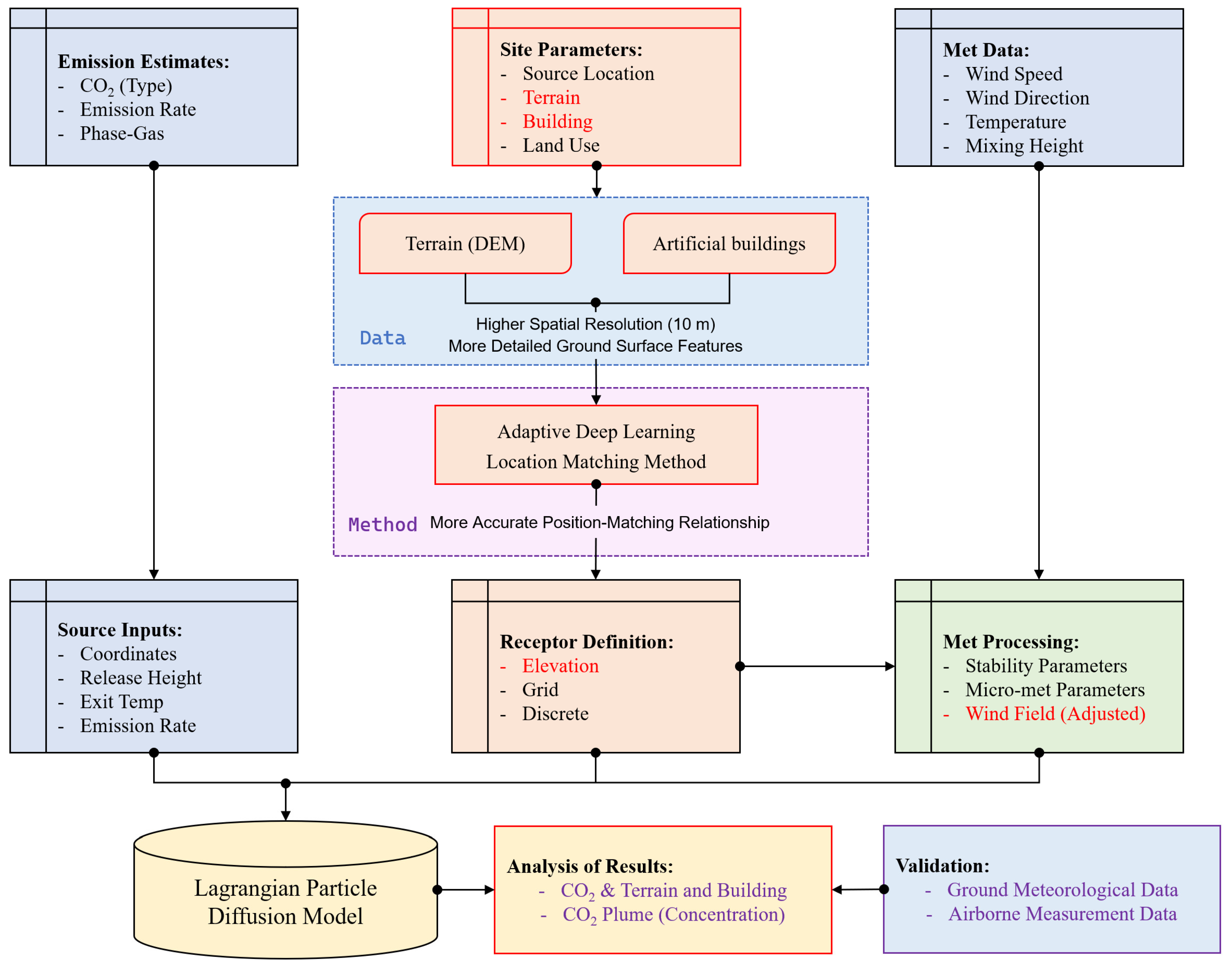
In Figure 7, the operational process of our proposed high-resolution atmospheric CO2 dispersion model based on the Lagrangian particle diffusion theory is presented. The process begins with input data, including the CO2 emissions inventory, surface characteristics, and initial meteorological dataset for the simulation area. Subsequently, the model goes through intermediate processing steps, leading to the final CO2 spatial distribution. This result is then compared and validated against actual measurements to assess the model’s accuracy and to validate the applicability of the surface dataset within the model.
Compared to existing atmospheric CO2 dispersion models based on the Lagrangian particle dispersion theory, as illustrated in Figure 7, the surface height feature datasets highlighted in red font in the flowchart represent the adjustments made in this study relative to the original model. These adjustments include dataset updates and corresponding data processing methods, corresponding to the blue and pink dashed boxes, respectively. Specifically, Section 4.1 and Section 4.2 will provide detailed explanations on the selection of the surface data setting, data characteristics, and data processing methods.

4.1. Data Selection

4.1.1. DEM

DEM is a digital depiction of the Earth’s surface elevation, presented in a two-dimensional matrix format. It is obtained using technologies such as LiDAR, InSAR, and Doppler radar, with the primary sources being the SRTM3 (Shuttle Radar Topography Mission), ASTER GDEM (Advanced Spaceborne Thermal Emission and Reflection Radiometer Global Digital Elevation Model), and ALOS (Advanced Land Observing Satellite) datasets.
Within the process of atmospheric CO2 dispersion, the undulating terrain along the transport path can locally affect CO2 dispersion, causing variations in CO2 concentration distribution due to factors such as valleys and canyons, terrain-induced changes in wind direction, and airflow alterations caused by elevation differences. DEM data can effectively represent local terrain features at a specific resolution, enabling the extraction of abundant surface morphology information, which can be utilized as topographic data in the simulation of atmospheric CO2 dispersion. High spatial resolution terrain data are vital in high-resolution settings, as they ensure the accurate representation of the real ground surface. The ability of these data to provide detailed information on ground elevation changes, mountainous areas, canyons, and other features greatly enhances the precision in determining variations in airflow pathways, velocities, and directions. Consequently, it better captures the complexities of atmospheric CO2 transport and dispersion dynamics.
The ALOS is a satellite developed and launched by the Japan Aerospace Exploration Agency (JAXA) on 24 January 2006. It carries three sensors: the Panchromatic Remote-sensing Instrument for Stereo Mapping (PRISM) for digital elevation mapping, the Advanced Visible and Near-Infrared Radiometer-2 (AVNIR-2) for precise land observation, and the Phased Array type L-band Synthetic Aperture Radar (PALSAR) for all-weather and all-day land observation [47]. ALOS DEM, with a horizontal and vertical spatial resolution of up to 12.5 m, is collected by the PALSAR sensor onboard ALOS. This sensor is equipped with high resolution and three observation modes: ScanSAR (Scan Synthetic Aperture Radar), Fine Beam, and Polarimetric modes. Considering that the highest spatial resolution provided by the atmospheric CO2 diffusion simulation in this study is 10 m, the 12.5 m ALOS DEM is resampled to a pixel size of 10 m to maintain consistency with the simulation settings [48]. The mathematical basis employs the 2000 National Geodetic Coordinate System (CGCS2000) and the Albers projection. The data pixels record the elevation of each point, and the elevation values are measured in meters.

4.1.2. Artificial Buildings

Artificially altering the topography, specifically referring to urban buildings, involves human activities that modify the shape and features of the Earth’s surface. It typically exhibits characteristics such as being localized, limited in scale, and being relatively small in scope. Artificial buildings obstruct air flow, leading to the formation of localized airflow patterns. Factors such as tall buildings, urban building clusters, and the arrangement of structures can modify the direction and velocity of nearby airflows, potentially causing CO2 to accumulate in certain areas or altering its flow trajectory. When dealing with high spatial resolutions, apart from the topographic variations that affect the atmospheric CO2 dispersion, the influence of building heights and layouts will further exacerbate the impact. Neglecting to consider these factors can significantly reduce the accuracy of atmospheric CO2 point source diffusion modeling.
Artificial building characteristics mainly consist of their outline and height information. The building outline data are essentially the vector data representing the boundaries of the buildings. In this study, we utilized the Microsoft Bing Maps, which publicly released the global building outline data (MLBuilding Footprints) on 17 May 2022. The dataset contains 776,712,641 building outline data and is continually updated and iterated, primarily relying on a combination of deep neural networks, ResNet34, and RefineNet’s upsampling layers to accurately monitor the building coverage areas on the map. The coordinate reference system used is EPSG 4326 (WGS-84). The building height dataset is mainly sourced from the China 10 m Building Height (CNBH) dataset published by the National Earth System Science Data Center [49]. This dataset is obtained using a combination of multi-source Earth observation data and machine learning techniques. The data are in raster format with a spatial resolution of 10 m, covering entire geographical extent of China. The dataset is projected in the WGS_1984_UTM_zone_51N coordinate reference system. By integrating the datasets of building outline and height, we can obtain detailed surface characteristics of artificial buildings. Adding the information of artificial building features allows us to further enrich the terrain information, providing vital information for analyzing the effects of surface terrain features on the atmospheric CO2 diffusion from point sources.

4.2. Adaptive Deep Learning Location Matching Method

4.2.1. Method Construct

Surface dataset encompasses information about terrain and topographic features, including elevation, terrain variation, and urban buildings. Nevertheless, the complex surface morphology alters the distribution of meteorological wind fields, especially the distribution of wind speed and direction. As the major driving force of CO2 dispersion, changes in wind speed and direction alter the paths and distribution patterns of the dispersion process. Therefore, accurately inputting surface morphology characteristics in the dispersion model is crucial for obtaining precise simulation results. Traditional approaches lack feedback between feature extraction and feature matching, resulting in feature extraction algorithms being unable to adaptively adjust based on the image being matched. In this study, a deep learning-based data location matching approach is proposed, which combines feature extraction and feature matching within a single end-to-end framework. It directly learns the mapping function from various data blocks to their corresponding matching labels. Considering the strong learning capacity of deep neural networks and the need for a large amount of labeled training data, we introduce a self-supervised remote sensing image matching approach, named the Adaptive Deep Learning Location Matching (ADLLM). This method automatically acquires numerous labeled training samples from the unregistered surface data.
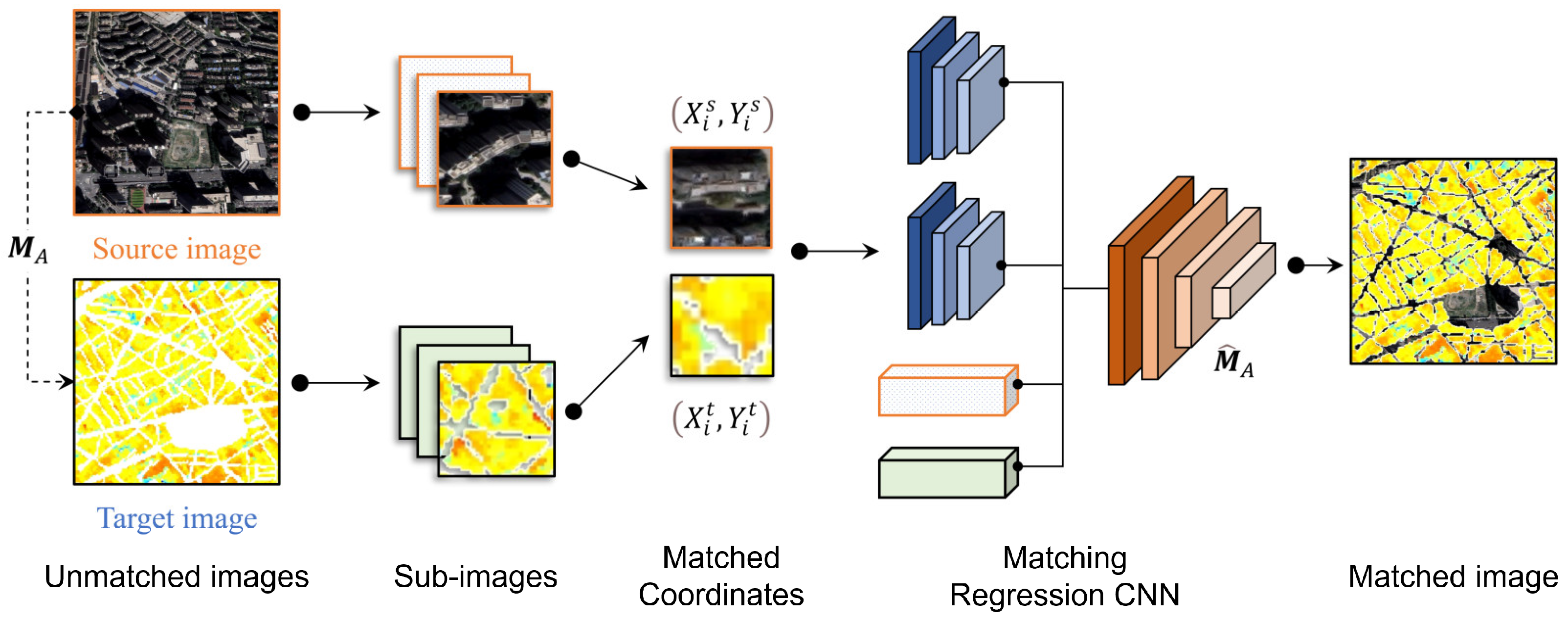
The ADLLM method differs from traditional feature-based image matching methods in that we unify feature extraction and feature matching within a deep learning framework. This enables us to directly learn the mapping between data blocks and their corresponding matching labels. In our network architecture, we feed two data blocks as input, and the network predicts their matching labels as output. Firstly, we use a deep neural network to learn the mapping from data block pairs to matching labels. Next, we employ the trained neural network to predict the matching relationship between data block pairs in the target image. Finally, we filter out incorrect matching point pairs, calculate the transformation matrix between the source and target images, and perform the matching of the DEM and artificial building datasets, as illustrated in Figure 8.
The purpose of the ADLLM method is to obtain corresponding image pairs with similar features of moderate size from the source and target images for subsequent estimation. Cropping image blocks instead of using sampled images as input allows for maximum retention of image details, and the additional coordinate information attached to the image blocks reduces the impact of severe geometric distortions between images. Simultaneously, during the matching process, it becomes easy to exclude regions with significant differences, thus enhancing the position matching accuracy. The proposed convolutional network is capable of associating features from two sub-images and predicting their similarity to identify matching pairs correctly.
Considering that the data source involves remote sensing images captured from a considerable distance, we opt for a normalized affine transformation characterized by the 6 degrees of freedom. This choice is better suited for near-range projections. The normalized transformation matrix, denoted as M A , is generated by the Enhanced Transformation Procedure (ETP) as opposed to using the original affine matrix M . Two variations of pixel transformation between the source and target images are indicated:
[ X i s X i s ] = M A [ X i t Y i t 1 ] = [ α 11 X i t + α 12 Y i t + α 13 α 21 X i t + α 22 Y i t + α 23 ]
[ X j s Y j s ] = M [ X j t Y j t 1 ] = [ β 11 X j t + β 12 Y j t + β 13 β 21 X j t + β 22 Y j t + β 23 ]
where ( X j s ,   Y j s ) and ( X j t ,   Y j t ) are the absolute pixel coordinates of points in the source and target images, and ( X i s ,   Y i s ) and ( X i t ,   Y i t ) are the normalized coordinates. α i j and β i j are the parameters of matrices M A and M , respectively. The transformation between absolute and normalized coordinates is defined as follows:
[ X i s Y i s ] = [ 2 H L X j s 1 2 W L Y j s 1 ]
where H L and W L represent the height and width of the image, respectively. The coordinates values of X i s , Y i s , X i t , and Y i t satisfy the conditions [ 1 , 1 ] , X j s , Y j s satisfy the conditions [ 0 , H L ] and X j s , Y j s have similar magnitude with a dynamic range of [ 0 ,   W L ] . Therefore, we can obtain the transformation matrices M A and M as follows:
[ α 11 α 12 α 13 α 21 α 22 α 23 ] = [ β 11 H L W L β 12 2 W L β 13 + β 11 + β 12 1 β 21 W L H L β 22 2 H L β 23 + β 21 + β 22 1 ]
where the parameter values of M A in the normalized transformation have magnitude with [ 2.5 ,   2.5 ] , making the conversion process easier. Meanwhile, the transformation matrix M varies greatly with the size of the image, which is not favorable for training.
The training process utilizes the grid loss [50], where we evaluate the discrepancy between the estimated transformation ( M ^ A ) and the actual ground truth transformation ( M t R ). The loss function is defined as follows:
( M ^ A , M t R ) = 1 N a ,   b = 1 N || T M ^ A ( X a , Y b ) , T M t R ( X a , Y b ) || 2
where ( X a , Y b ) represents the normalized point coordinates, N is the count of grid points, and T is the transformation operator that converts coordinates.
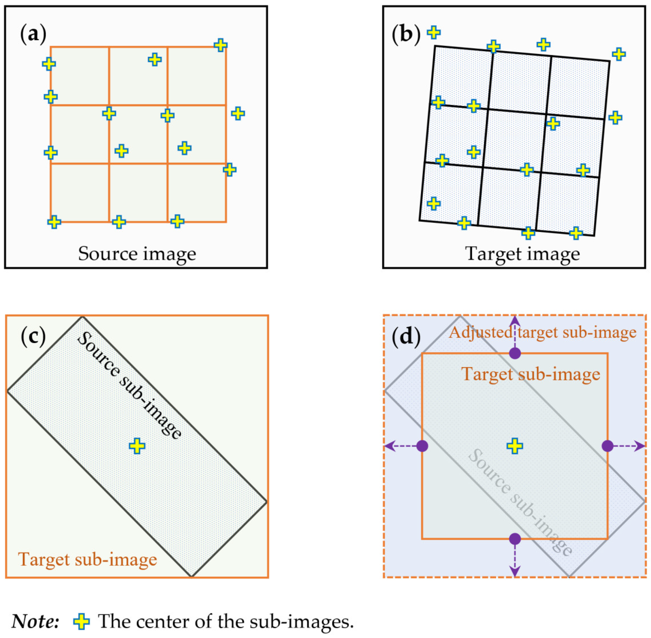
However, the traditional techniques for feature extraction precisely identifies corresponding points, while the matching of corresponding sub-images is area-based rather than point-based. In this approach, regions within a specific vicinity can be considered as valid correspondences. During the creation of training samples, rectangular regions are transformed from the source sub-images into quadrilateral areas. These areas often possess bounding windows that may not align exactly with the dimensions of the target sub-image windows. When extracting positive samples from target images, these windows can either fit within the bounding rectangles or entirely contain them, as depicted in Figure 9c,d. As a result, in order to address this, we introduce a method to enhance training by augmenting target sub-images [51]. Instead of relying on exact centers transformed from the source sub-images, random cropping within this predefined scope is employed. This augmentation strategy is employed during both Matching Sub-image (MSI) and ETP training stages. It serves to prevent overfitting by avoiding fixed coordinates and neglecting image features. Additionally, this approach simulates sub-image offsets during the matching process, as illustrated in Figure 9a,b.

4.2.2. Position Matching Accuracy Evaluation

We conducted a comprehensive comparison between the ADLLM method and six traditional techniques, namely feature point matching [52], correlation matching [53,54], spatial interpolation [55], support vector machine (SVM) [56], random forest [57], and topological matching [58,59,60] (specified in Table 1). The evaluation was carried out using GPS location values as the reference [61], and the results are shown in Figure 10. The GPS position values were obtained through the GNSS (the Global Navigation Satellite System) Real-Time Kinematic (RTK)/UWB/DBA Fusion Positioning Method, which can achieve a positioning error of less than 5 cm under a 50-degree elevation mask angle [62].
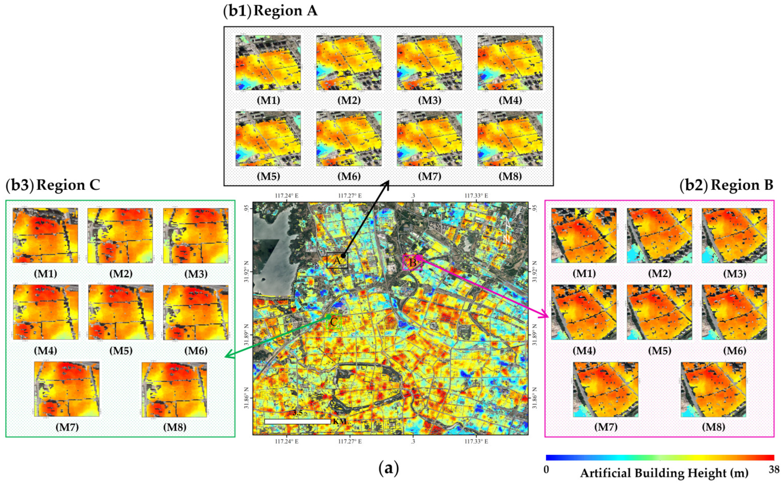
Figure 10 showed the study area situated in the vicinity of the Wanneng (WN) Power Plant in Luyang District, Hefei, Anhui Province, China. We compared the results of seven different location matching methods, denoted as (M1–M7), and (M1–M6) correspond to the six traditional methods listed in Table 1. The images are labeled with (M1–M7) in sequential order, corresponding to the six methods listed in Table 1, and the ADLLM method proposed in this study. Label (M8) corresponds to the reference results obtained through GPS location matching. Additionally, Figure 10a represents the overall matching results of artificial buildings in the entire area, and Figure 10b corresponds to the zoomed-in matching results for Regions A–C, which were selected from Figure 10a.
By observing the location matching results of DEM and artificial buildings in Figure 10, it becomes apparent that the ADLLM method (M7) presented in this research demonstrates a strong agreement and minimal positional deviation with the results in Regions A–C and the GPS-based positioning reference (M8). When comparing the results in (M1), (M2), and (M3) with (M7), it is evident that the feature point matching, correlation matching, and spatial interpolation methods exhibit significant lower-left positional deviation of the artificial buildings relative to DEM. Particularly, they fail to align accurately along the river boundaries in the DEM. This indicates that commonly used position matching methods may lead to noticeable positional discrepancies when dealing with fine-grained image data. In Figure 10 (M4) and (M5) for all regions, corresponding to the SVM and random forest methods, there is a noticeable improvement in the accuracy of the location matching results compared to the three methods (M1–M3). However, there is still an apparent upward and rightward positional deviation concerning the GPS reference results. Among them, the random forest method outperforms the SVM method in this data matching, which can be attributed to its superior noise resistance and ability to handle complex relationships between non-linear features using kernel functions. These advantages are not present in the SVM method. The topological matching method in Figure 10 (M6) shows an additional enhancement in the accuracy of the location matching compared to the five previous methods. Nevertheless, there is still a clear positional offset concerning the GPS-based reference results. Particularly, the artificial buildings exhibit a noticeable upper-right corner shift concerning the DEM results, though the offset is smaller than the location matching results of the previous five methods.
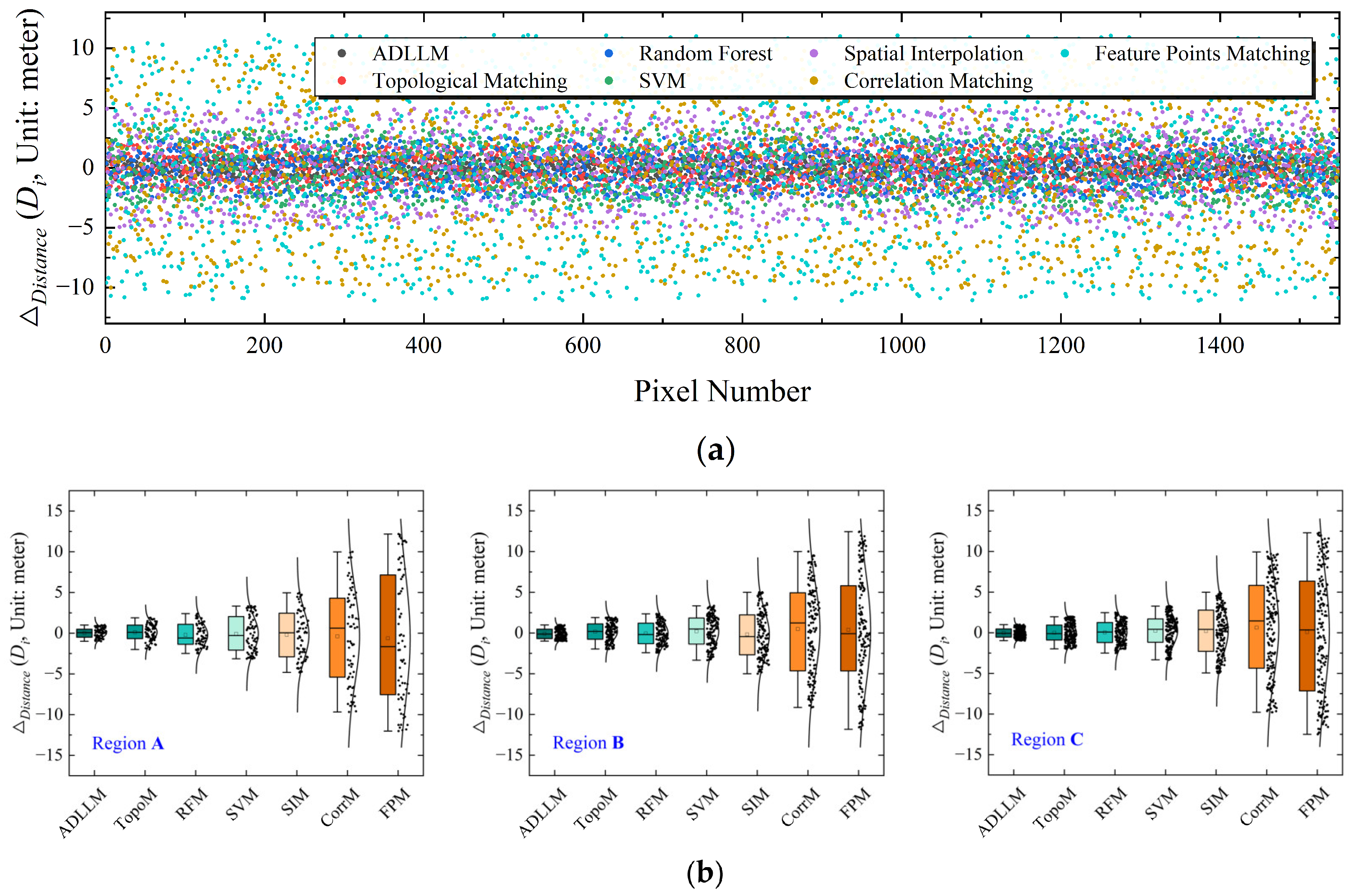
To illustrate the accuracy of the artificial building location matching results further quantitatively, this study introduces the distance calculation method based on the following Formula (12). This method involves computing the distance between all artificial building location points and the corresponding points in the GPS-based reference results. The calculated distances are then used to analyze the deviation of the seven methods mentioned above from the true corresponding positions after location matching.
D i = ( L a t γ L a t 0 ) 2 + ( L o n γ L o n 0 ) 2 × D N
where L a t γ and L o n γ represent the latitude and longitude, respectively, of a point obtained after using one of the mentioned methods. L a t 0 and L o n 0 correspond to the latitude and longitude of the GPS-based matching result, with only degree ( ° ) values considered as the reference. D N = 111.31955   km / ° is constant, which represents the conversion factor of degrees to distance length at the equator. D i represents the distance difference between the result obtained from the method and the GPS-based matching result. Figure 11 presents the results obtained from the calculation using Equation (12). The distance differences between the seven methods in both the entire area Figure 11a and the three local magnified areas (Regions A–C, Figure 11b) are compared and displayed. Notably, significant variations in the distance differences from the true positions exist among the seven methods, and the dispersion of points also varies. The ADLLM method exhibits the most favorable performance.
By comparing the distance deviations point-to-point, it is evident that the seven methods exhibit varying degrees of differences when matched with the GPS-based positioning results, both in the entire area and the three local zoomed-in regions (Regions A–C). Among them, the traditional feature point matching method exhibits the largest positional deviation, with actual distance differences reaching up to ±15 m. In contrast, the proposed ADLLM method demonstrates a significantly smaller and more tightly clustered distribution of distance deviations, centered around the Y = 0 axis. The quantitative comparison and analysis of the D i values (in meters) mainly fall within the range of [−1,1], indicating a very close agreement with the GPS-based matching results. The traditional positioning matching methods, particularly the SVM and Random Forest, representing early deep learning algorithms, exhibit significant improvements in reducing the dispersion of distance deviations compared to direct spatial positioning matching or interpolation methods. This highlights the superior performance of the deep learning-based method proposed in this study for high spatial resolution location matching. Furthermore, this study introduces three metrics—the correlation coefficient (R2), mean absolute error (MAE), and root mean square error (RMSE) (listed in Table 2)—to analyze the spatial relationship between the latitude and longitude of the artificial buildings in the matched images and the GPS positioning reference points. The results indicate that the proposed ADLLM method outperforms the other six methods, exhibiting higher correlation and smaller position deviation relative to the reference location. Specifically, the R2 value is 0.962, the MAE is 0.14 m, and the RMSE is 0.167 m.
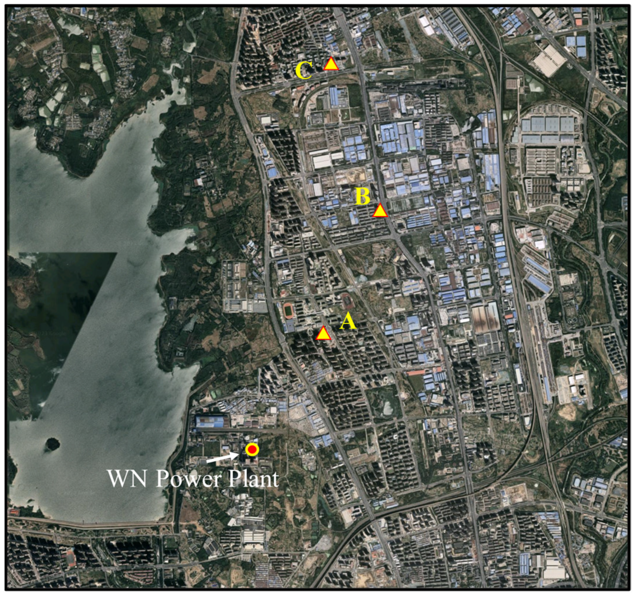
The study area around the WN Power Plant in Luyang District, Hefei City, Anhui Province, China, was chosen as the simulated object. The CO2 concentration was continuously measured using the photoacoustic spectroscopy multi-gas analyzer (Gasera One, Duke Technology Co., Ltd.) and was used for validating plume simulations. This instrument offers several advantages, such as high measurement accuracy, low detection limit, real-time monitoring capability, on-site and online measurements, and high efficiency. Specifically, the Gasera One can provide ppb sensitivity for reliable measurement of background levels of greenhouse gases, allowing it to detect minute changes in concentration with almost no time delay [63,64,65]. Figure 12 shows the spatial layout of the measurement experiment, which includes three observation points labeled as A, B, and C. The Gasera One was mounted on the rooftop of a building for data collection. Meanwhile, the straight-line distances from the emission source of the power plant to the three observation points A–C are 3.17 km, 8.96 km, and 18.75 km, respectively.
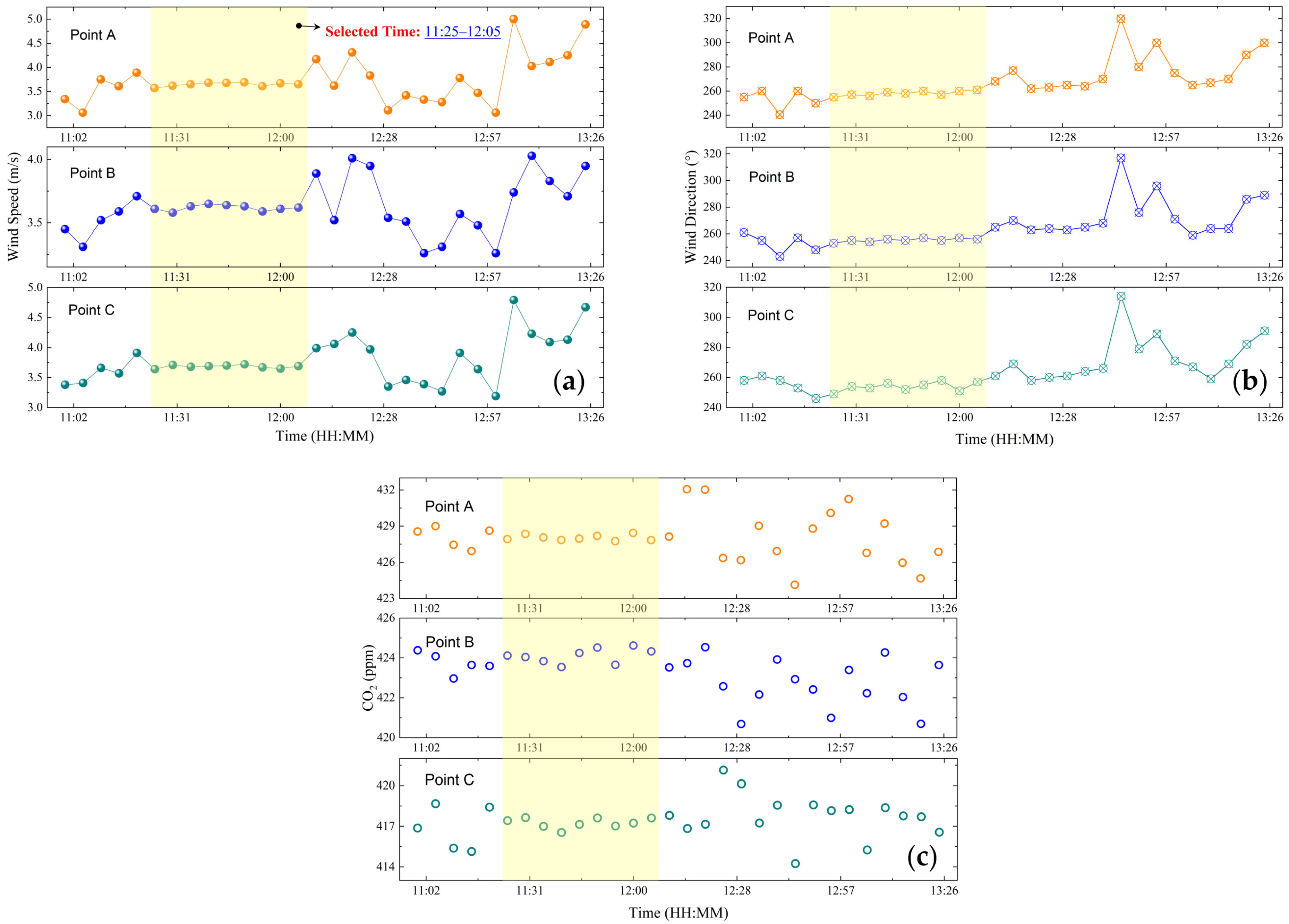
This experiment was carried out on 2 April 2022. The objective at that time was to collect ground-based observational data for subsequent CO2 emission estimation from the WN Power Plant. In Figure 13a,b, we present the variations in wind direction and speed for three points, A–C, from 11:00 to 13:25 on 2 April 2022. Considering the irregular variations in wind direction and speed might increase the uncertainty of the CO2 simulation comparison, we filtered the available observational data temporally. We selected data that had a stable wind direction and small wind speed gradient variations over time. Only the time period from 11:25–12:05 on 2 April 2022 met these conditions, indicating that such weather conditions are quite rare. Using the stable variation conditions of wind direction and speed, we also selected a corresponding period for CO2 mole fraction results from ground-based Gasera One photoacoustic spectrometer observations, as illustrated in Figure 13c. It can be observed that CO2 exhibits significant stability within the selected time period. Compared to the unselected area, the CO2 trend is notably steady, and the deviation for each time point is relatively small.
Meanwhile, we also compared the standard deviations between the measured values and the calculated average values of wind speed, direction, and CO2 mole fraction at each time point within the selected period from 11:25 to 12:05, as shown in Table 3. It is evident that the wind speed deviations for Points A–C are generally less than 0.05 m/s, with Point B having the smallest deviation. The deviations for wind direction are less than 2.67° overall, with Point B again having the smallest deviation and Point C having a larger one. The CO2 deviations are generally less than 0.48 ppm, with Point A having a deviation of 0.4785 ppm, the largest among the three points. This indicates that using the average values of the three points as the measurement values for validation in Figure 14c can satisfy the actual verification requirements, reflecting the magnitude of the values within the selected time range with relatively small deviations.
We utilized the position-matched surface feature datasets generated by these two methods as inputs for the point source CO2 diffusion simulation. The simulation was conducted for WN Power Plant, with coordinates at (31.9168°N, 117.2657°E), CO2 emission rate of 79.8 Mt/yr, and gas exit velocity of 7.82 m/s. During the simulation process, all parameters were kept constant, except for the surface elevation dataset, which was processed using two different methods. The CO2 mole fraction results obtained from Gasera One observation were used as the verification dataset, and the atmospheric CO2 dispersion simulation outcomes are illustrated in Figure 14.
By comparing the results of atmospheric CO2 diffusion simulation between the traditional location matching and ADLLM methods, as shown in Figure 14, we can observe significant differences in plume morphology. The CO2 distribution in different positions of the CO2 plume varies notably between the two methods, and the extent of the diffusion is also different. The traditional location matching method exhibits a smoother CO2 simulation result compared to the ADLLM method because of the positional discrepancies, which fail to accurately represent the height variations of different surface objects. As a result, the CO2 simulation results using the traditional method do not show the true variations in surface elevation and are less affected by surface features.
Furthermore, we compared the simulation results of both methods with the Gasera One observation, specifically for three actual measurement locations, points A, B, and C. In Figure 14c, the simulated CO2 mole fraction results at three specific heights (the heights corresponding to points A, B, and C are 68.5 m, 72.1 m, and 78.3 m, respectively) for these points using the ADLLM method exhibit minimal differences compared to the Gasera One observation, with an average difference of 1.43 ppm. On the other hand, the traditional location-matching method, represented by the topological matching method, shows more significant differences, with an average difference of 5.35 ppm compared to the Gasera One observation.
During the same time period of 11:25 to 12:05, we compared the average CO2 measurement values with our simulation results. The standard deviations between CO2 simulation results based on the ADLLM method and the topological matching method and the measured CO2 mole fraction results are shown in Table 4. The CO2 simulation results based on the ADLLM method have an overall deviation of less than 0.65 ppm when compared to the actual measurements, with Point A having the smallest standard deviation of 0.3187 ppm. However, the CO2 simulation results based on the topological matching method show a greater deviation when compared to the actual measurements than those based on ADLLM, with an average standard deviation of 2.4531 ppm. The smallest deviation is at Point A, while the largest is at Point C.
Through the verification and analysis of the direct location matching results of six traditional location matching methods and the ADLLM method, along with the corresponding CO2 diffusion simulation results, it can be concluded that the ADLLM method, when applied to the artificial building dataset, significantly improves the accuracy of CO2 dispersion simulation. The ADLLM method shows higher consistency with GPS-based positioning results and exhibits smaller location deviations. Consequently, it provides more reliable CO2 simulation results at observation points A–C compared to the traditional location matching methods. The ADLLM method’s ability to accurately match the artificial building dataset plays a crucial role in enhancing the overall accuracy of CO2 dispersion simulation. To further validate the point source CO2 diffusion simulation results, a subsequent aerial flight experiment was conducted for the Yangzhou Power Plant in Jiangsu Province, China, using aerial remote sensing observations.

5. Aircraft Measurement Validation

5.1. Aircraft Measurement of Power Plant Plumes

5.1.1. Instruments and Experimental Subject

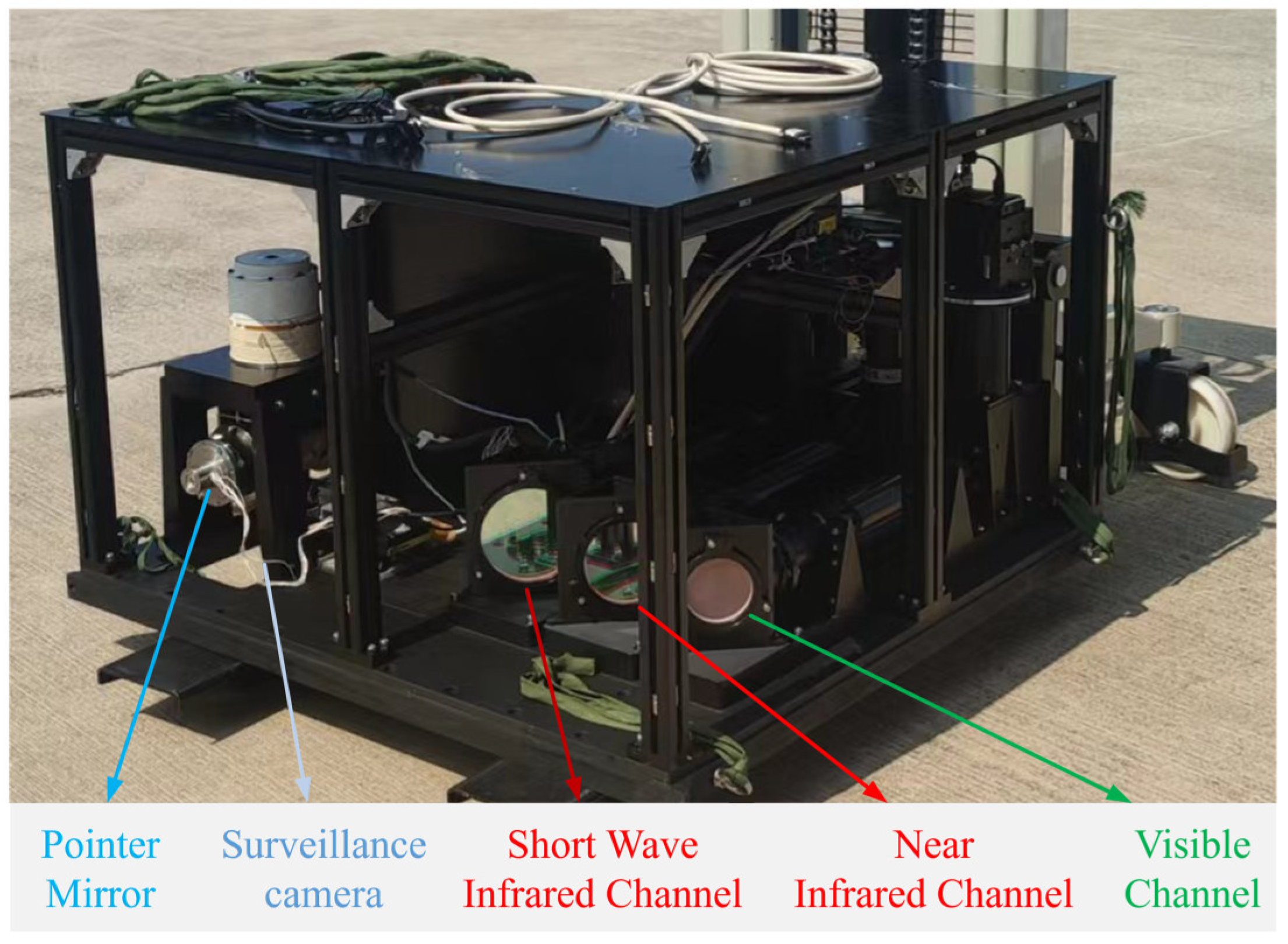
The experiment employed an atmospheric major greenhouse gas monitoring instrument that utilizes spatial heterodyne imaging spectroscopy (SHIS) technology [66]. This instrument can acquire both the image and spectral information of the target. Its main components include a far-field imaging mirror group, interference components, a rear imaging mirror group, and a detector. The physical appearance is shown in Figure 15. Due to the use of interferometric spectroscopy measurement technology, this instrument can achieve extremely high-resolution and high-quality spectral data.
The SHIS instrument includes three observation bands—visible, near-infrared, and shortwave infrared—with center wavelengths of 0.76 μ m , 1.56 μ m , and 2.04 μ m , respectively. The main technical parameters of each channel imaging spectrometer are shown in Table 5 below. The SHIS observational data employ the optimal estimation algorithm in the physical retrieval method, achieving an XCO2 retrieval accuracy better than 2.7 ppm [7,67].
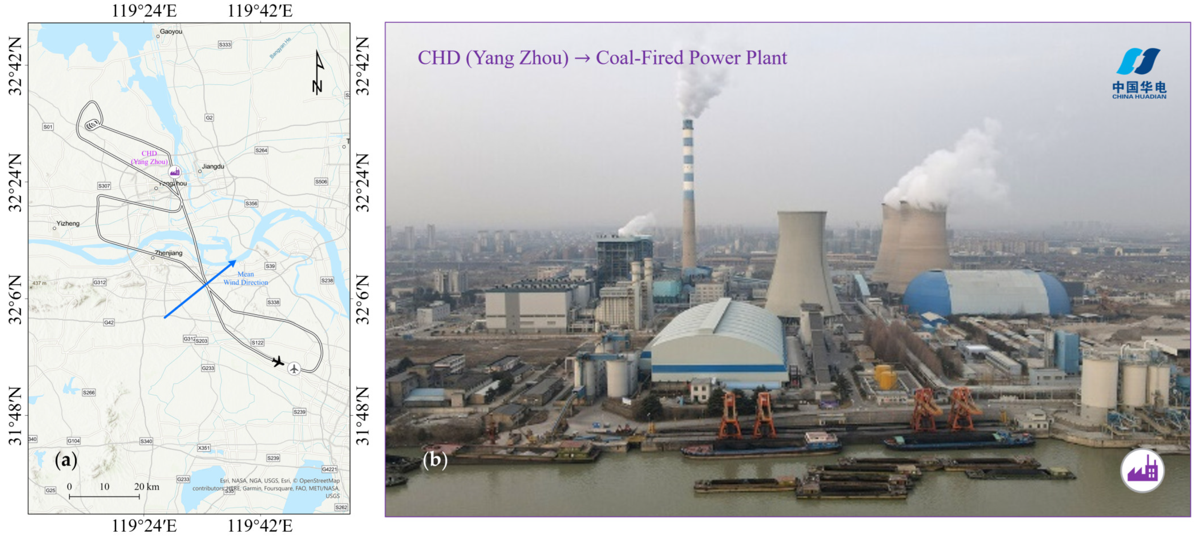
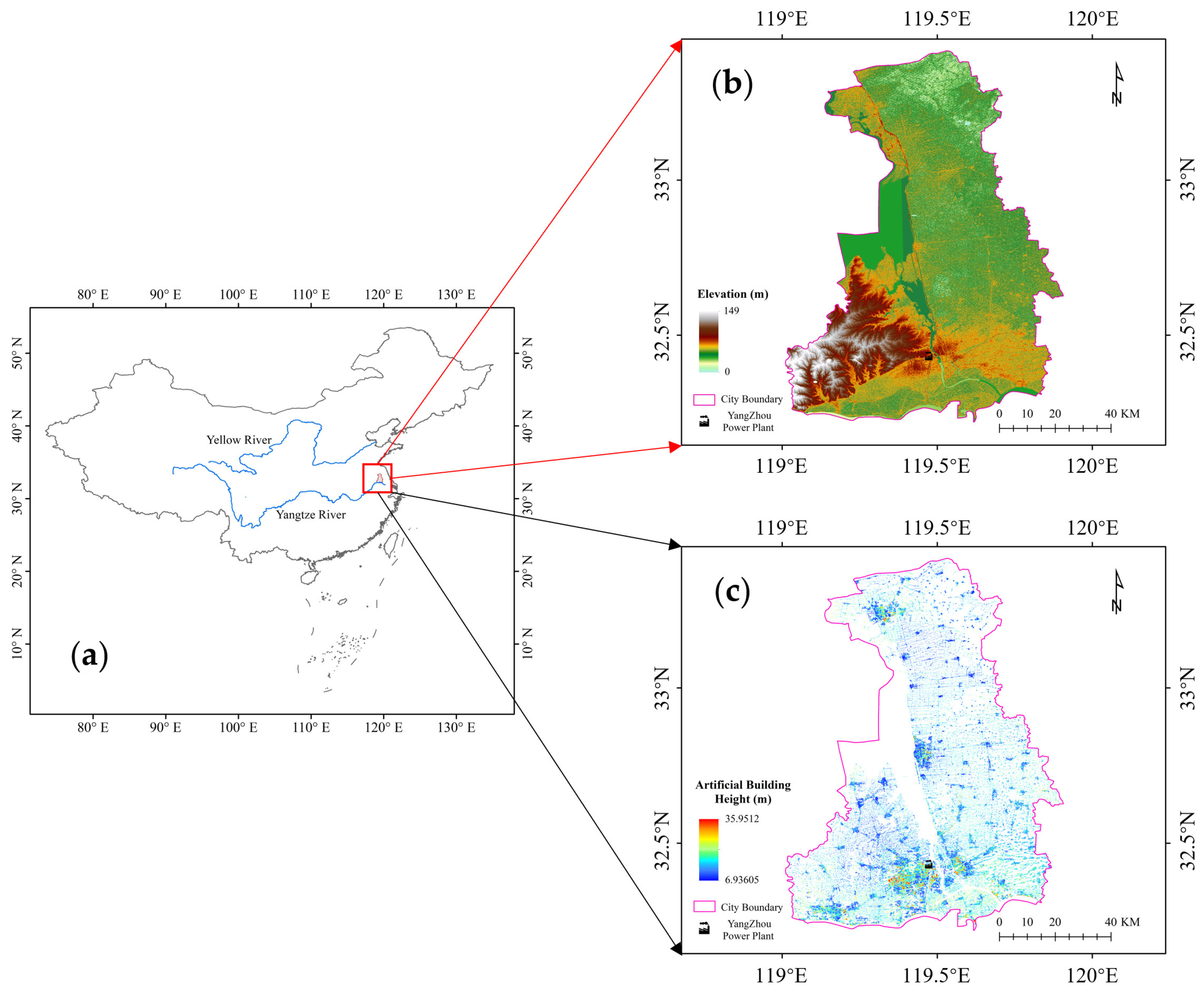
The experiment selected the aerial flight plan over the Huadian Power Plant (see Figure 16). The power plant is a coal-fired power plant located in Jiangdu District, Yangzhou City, with a total installed capacity of 1610 megawatts (MW), comprising two units of 330 MW coal-fired generators and two units of 475 MW coal-fired generators. According to public data, the annual CO2 emissions of Huadian Power Plant in Yangzhou City were approximately 53.02 million tons in 2019. The location information (a) and an on-site photograph (b) of the Huadian Power Plant are shown in the figure below (Figure 16).
On 6–7 August 2022, two flight missions were conducted for aerial observation. The flight on August 6 was primarily used for aircraft and instrument calibration, as shown in Figure 16. The aerial observation test route was conducted on 7 August using a Kodiak KODIAK-100 aircraft, flying at 1500 m height and a speed of 200 km/h. The flight pattern allowed for a swath width of 89 m and a single pixel spatial resolution of 0.139 m in the cross-track direction. Considering the stability of the instrument during flight and the low signal-to-noise ratio of single pixels, the acquired aerial data were merged into 70 pixels in the cross-track direction. Along the track, channels at 0.76 μ m and 2.04 μ m were merged every 5 pixels, while the 1.56 μ m channel was merged every 2 pixels. After pixel merging, the spatial resolution of a single pixel in both along-track and cross-track directions was 9.73 m, which is consistent with the high spatial resolution CO2 dispersion model simulated in this study.

5.1.2. Ground Meteorological Observation

Meteorological parameters, especially wind speed, are critical factors that drive the diffusion of emitted gases and determine the shape and concentration distribution of emissions. To validate the accuracy of the simulation based on the complex surface wind field, this study selected data from five meteorological stations in Yangzhou City, including international cooperation station, national meteorological reference station, and provincial/municipal meteorological stations. To address the issue of data gaps in the dataset, where certain hourly observations of wind direction, wind speed, temperature, and other parameters were missing, linear interpolation was employed to fill in the missing values [68].
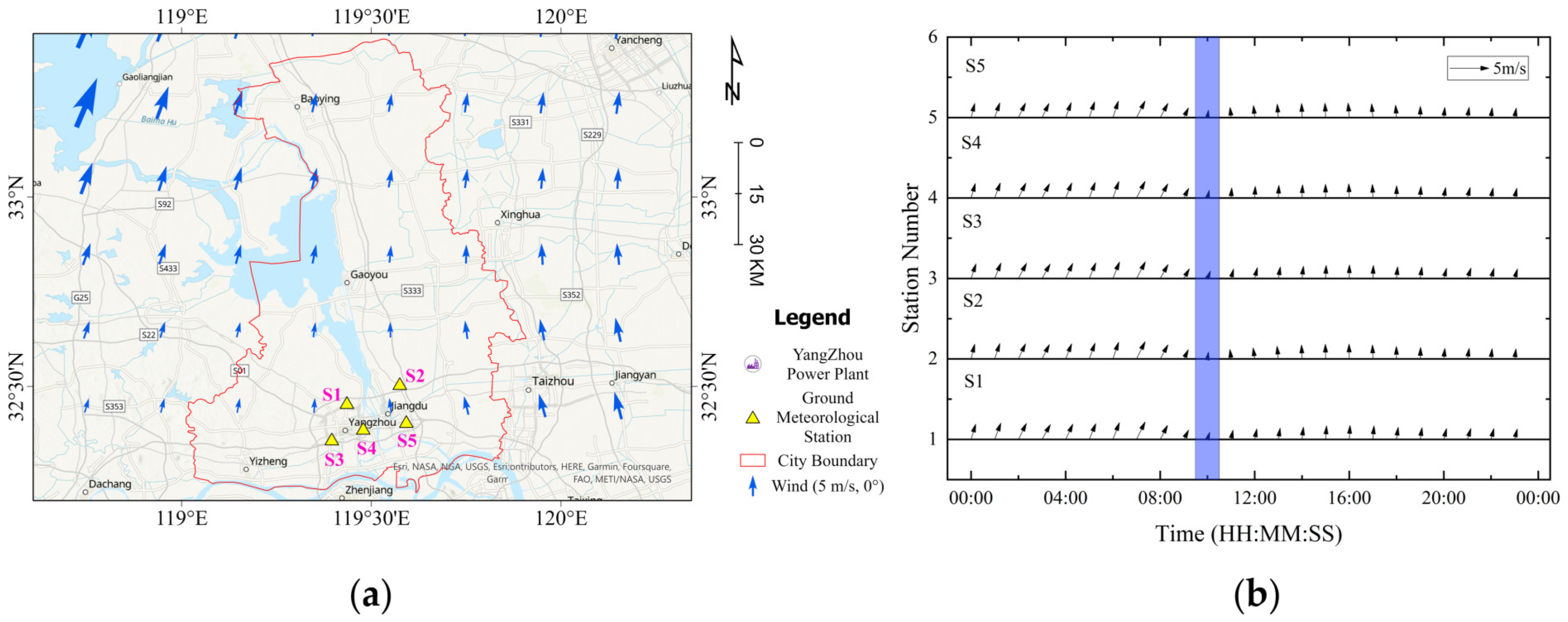
Through the theoretical simulation and analysis presented earlier, it was found that the high-resolution DEM and artificial building features directly influence the near-surface wind field characteristics, thereby causing differences in the spatial distribution of CO2 diffusion simulation. We matched the output meteorological variables from the simulation process with the ground meteorological stations within the region and obtained the results shown in Figure 17. In Figure 17a, the wind direction and speed around the power plant on 7 August 2022 were simulated using the high-resolution CO2 dispersion model, showing a predominant south-southwest (SSW) wind direction with an average wind speed of 2.3 m/s.
Figure 17b shows the real-time wind direction and wind speed results from five ground stations (S1 to S5) at hourly intervals over a 24-h period. Since the meteorological stations are located close to each other, there were minimal differences in wind direction and wind speed among the five stations over time. The purple rectangular box in Figure 17b highlights the area with wind direction and wind speed results corresponding to the same time as in Figure 17a. A direct comparison shows that the simulated wind direction and wind speed results are in excellent agreement with the ground monitoring results from the five stations, with no significant differences observed between simulation and measurement.
The comparison analysis between the wind speed and wind direction simulated by the model and the observations from the five ground meteorological stations showed high correlation. The R² values for wind speed and wind direction are 0.837 and 0.853, respectively. These results indicate a good agreement between the simulations and the actual observations, with small deviations.
However, the wind speed simulation showed relatively larger deviations compared to the wind direction simulation and actual observations. This discrepancy may be attributed to differences in the height at which the ground meteorological stations are installed and the output height of the simulation, even though both provide near-surface results.

5.2. Model Parameters Setting

The study area selected with dimensions of 10 km × 10 km centered around the Huadian Power Plant. The initial meteorological field data used in the simulation was obtained from the Weather Research and Forecasting Model (WRF), which was developed by research institutions such as the National Centers for Environmental Prediction (NCEP) and the National Center for Atmospheric Research (NCAR) in the United States. The surface dataset used in the simulation consists of the high spatial resolution DEM and the artificial buildings dataset proposed in this paper, as shown in Figure 18.
From the terrain data presented in Figure 18 around the Huadian Power Plant, it can be observed that there is a noticeable terrain elevation on the west side of the power plant, which is higher compared to the other three directions. Additionally, according to the land use type data, the power plant is surrounded by artificial buildings with a spatial resolution of 10 m.
The object of simulation is the Yangzhou Huadian (CHD) Power Plant in Yangzhou City. Its main greenhouse gas emissions include CO2, CO, CH4, and H2O. This thermal power plant is a state-controlled pollution source. For this study, CO2, representing the most representative greenhouse gas emission, was selected as the subject for diffusion simulation. The emission intensity was obtained from real-time monitoring data provided by the National Key State-Controlled Pollution Monitoring Platform. The main parameters for the emission source are shown in Table 6.

5.3. Quantitative Comparison and Analysis

For the specific location and time of the experiment centered around the Yangzhou Huadian Power Plant, the data preprocessing was conducted based on the obtained initial meteorological field data, high-resolution DEM data, artificial building data, and CO2 emission parameters from the power plant chimney. Using the ADLLM data processing methods described in this paper, the CO2 plume from the power plant was simulated. The simulated plume is stratified, and for verification and comparison with experimental results, the stratified results were integrated into spatial distributions of column concentration. The simulated CO2 column concentration results were then compared with the results obtained from the airborne remote sensing experiment.
The spatial distribution of atmospheric carbon dioxide column concentration, i.e., XCO2, and its dispersion pattern are shown in Figure 19. In Figure 18a, the flight trajectory includes a segment over the power plant area with a length of 10 km. Figure 19b presents the intersection of the XCO2 simulation results and the flight experiment results. Figure 19c displays the XCO2 retrieval results based on the airborne remote sensing measurement data. It shows that within the flight trajectory over the power plant area, the XCO2 values are significantly elevated, reaching a maximum of 425 ppm. The XCO2 gradually decrease in the north–south direction. Gaussian fitting analysis reveals that the power plant region corresponds to the peak of the Gaussian fit curve (maximum XCO2 value).
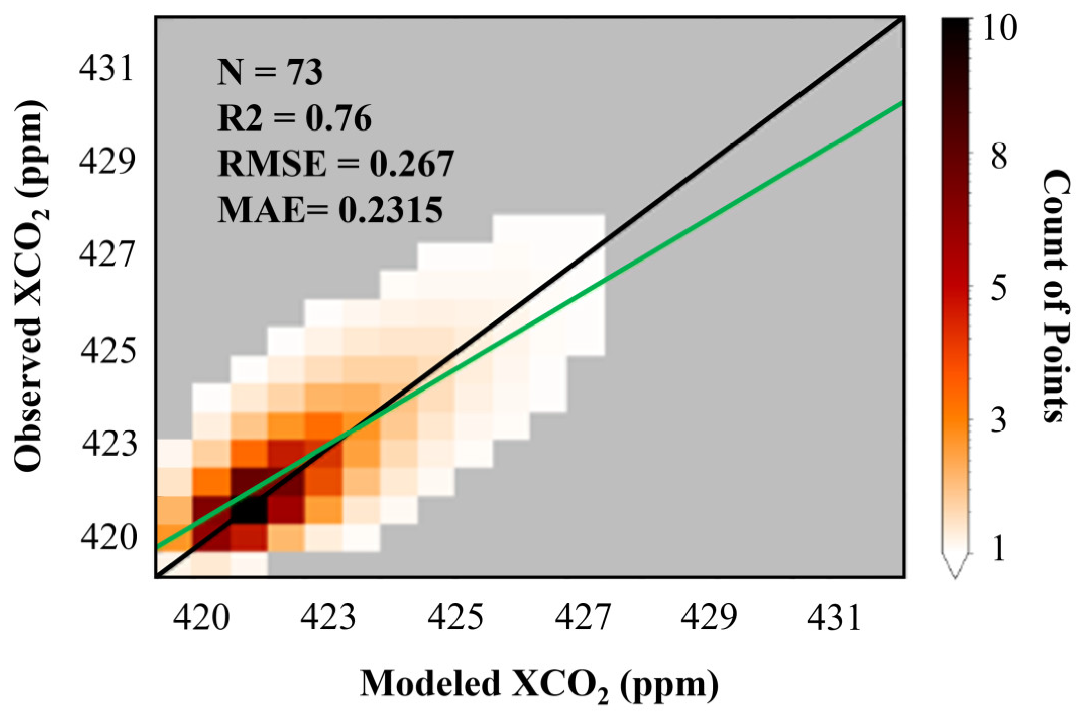
The simulation results were verified for accuracy against the airborne observation data on a point-by-point basis (represented by the intersecting pixels in Figure 19b), and the validation results are presented in Figure 20 and Table 7. A total of 73 intersecting pixels were identified between the simulation and observation results. By comparing these values, the maximum XCO2 values were found to be 428 ppm and 425 ppm for the simulation and airborne observation, respectively, with a difference of 3 ppm. The minimum values were 412 ppm and 410 ppm, with a difference of 2 ppm. The average values were 418 ppm and 416.3 ppm, with a difference of 1.7 ppm. It was observed that the simulation results slightly overestimated the XCO2 values compared to the airborne observation, but the differences were small.
Additionally, the quantitative comparison between the simulation and observation revealed the R2 of 0.76, the RMSE of 0.267 ppm, and the MAE of 0.2315 ppm. These results indicate a high correlation and small deviations between the simulated and observed XCO2 values, signifying the high accuracy of the XCO2 simulation results. Moreover, the simulated CO2 plume distribution exhibited good agreement with the airborne observation results at the intersecting pixel locations, indicating accurate representation of the CO2 plume’s diffusion pattern.
Through the precision validation of the XCO2 simulation results, it was found that the use of high-resolution surface models based on deep learning position matching algorithms (high-resolution DEM and refined artificial building features) significantly improved the accuracy of CO2 plume simulation. This approach also reduced the deviation from airborne observation results and provided an important numerical simulation tool for high-precision CO2 diffusion and transport simulations in the future.

6. Conclusions

To accurately quantify the diffusion characteristics of CO2 emissions from high-emission point sources, this study conducted research on the atmospheric CO2 dispersion model under high spatial resolution. Using the Lagrangian particle diffusion as the theoretical basis, the impact of surface topography and artificial building features on atmospheric CO2 diffusion under high spatial resolution conditions was analyzed. Ground-based and airborne observation experiments were also conducted to verify the capabilities of the deep learning-based position matching method and the accuracy of the high spatial resolution point source atmospheric CO2 dispersion model.
Under high spatial resolution conditions, the surface features have a significant impact on the atmospheric CO2 dispersion, including the variations in DEM and artificial building features, which in turn affect the speed and direction of atmospheric CO2 diffusion by altering the distribution of meteorological fields. Therefore, the development of a high-precision surface terrain feature processing method is crucial to improving the accuracy of diffusion simulations. In this study, simulations of typical building distributions showed complex variations in wind fields as they passed through buildings. Based on this, the ADLLM method was proposed for the positioning of surface datasets, addressing the errors in the transformation and processing of surface terrain data. Through the comparative analysis of the ADLLM and six traditional location matching algorithms, and validation with ground-based Gasera One photoacoustic spectrometer observations, the average difference in measured CO2 mole fraction was 1.43 ppm, much lower than other traditional matching methods, verifying the good performance of ADLLM in high-resolution point source CO2 simulations. Furthermore, verification was conducted through airborne remote sensing experiments at a power plant in Yangzhou, Jiangsu Province, China. The comparison between simulated wind fields and ground meteorological station data revealed an average R2 of 0.837 for wind speed and 0.853 for wind direction, respectively. In comparison with airborne observations, 73 overlapping pixels were found, and the R2 and RMSE for XCO2 were 0.76 and 0.267 ppm, respectively. The actual comparison showed high consistency between the model simulation and the observed XCO2 results, as well as the wind speed results, confirming the accuracy of the high spatial resolution atmospheric CO2 dispersion model.
This study quantitatively analyzed the impact of surface features on high-resolution point source atmospheric CO2 diffusion simulations and accurately incorporated this factor into a high-resolution CO2 dispersion model, thereby improving the accuracy of atmospheric CO2 concentration field simulations. This research provides essential technical support for the accurate quantification of anthropogenic CO2 emissions in future top-down methods. Meanwhile, in order to be more widely applied to the study of other greenhouse gas emissions such as CH4 and CO [69], expanding the application of the improved point source diffusion model described in this paper to different types of gases will be the next research direction. This will further enhance the reliability and applicability of the model presented in this article.

Author Contributions

All authors contributed in a substantial way to the manuscript. Conceptualization, C.L. and X.W.; methodology, C.L., X.W. and H.Y.; software, C.L. and H.Y.; validation, C.L. and S.W.; formal analysis, C.L., X.W. and H.Y.; investigation, C.L.; resources, X.W., H.Y., H.S., W.X., H.L. and Z.L.; data curation, C.L., S.W., Y.A. and Z.L.; writing—original draft preparation, C.L.; writing—review and editing, C.L. and X.W.; visualization, C.L., E.S., S.W. and Y.A.; supervision, S.W. and E.S.; project administration, X.W., W.X., H.Y., H.S. and D.L.; funding acquisition, X.W., W.X., H.Y., H.S. and S.W. All authors have read and agreed to the published version of the manuscript.

Funding

This research was supported in part by the National Key R&D Program of China (2021YFE0118000), and in part by the National Natural Science Foundation of China (NSFC) Young Scientist Fund (42205146).

Data Availability Statement

Not applicable.

Acknowledgments

The Lagrangian Particle Dispersion Theory Model provided by Engineering and Scientific Consulting (Exponent, http://www.src.com/, accessed on 12 September 2023) is acknowledged with our gratitude. We would also like to acknowledge the 12.5 m ALOS DEM datasets provided by JAXA, the global building outline datasets provided Microsoft Bing Maps, and the 10 m building height datasets provided the National Earth System Science Data Center. Meanwhile, we thank for providing initial and boundary conditions for WRF simulations, the wind profile dataset provided by the National Centers for Environmental Information (NOAA) Profiler Network (NPN) and the factory GHGs emission data provided by the National Key State-Controlled Pollution Monitoring Platform.

Conflicts of Interest

The authors declare no conflict of interest.

References

  1. Pörtner, H.-O.; Roberts, D.C.; Adams, H.; Adler, C.; Aldunce, P.; Ali, E.; Begum, R.A.; Betts, R.; Kerr, R.B.; Biesbroek, R. Climate Change 2022: Impacts, Adaptation and Vulnerability; IPCC Sixth Assessment Report; IPCC: Geneva, Switzerland, 2022. [Google Scholar]
  2. Lamb, W.F.; Wiedmann, T.; Pongratz, J.; Andrew, R.; Crippa, M.; Olivier, J.G.J.; Wiedenhofer, D.; Mattioli, G.; Al Khourdajie, A.; House, J. A Review of Trends and Drivers of Greenhouse Gas Emissions by Sector from 1990 to 2018. Environ. Res. Lett. 2021, 16, 073005. [Google Scholar] [CrossRef]
  3. Whitaker, M.; Heath, G.A.; O’Donoughue, P.; Vorum, M. Life Cycle Greenhouse Gas Emissions of Coal-fired Electricity Generation: Systematic Review and Harmonization. J. Ind. Ecol. 2012, 16, S53–S72. [Google Scholar] [CrossRef]
  4. Butz, A.; Guerlet, S.; Hasekamp, O.; Schepers, D.; Galli, A.; Aben, I.; Frankenberg, C.; Hartmann, J.; Tran, H.; Kuze, A.; et al. Toward Accurate CO2 and CH4 Observations from GOSAT. Geophys. Res. Lett. 2011, 38, 14. [Google Scholar] [CrossRef]
  5. Wunch, D.; Wennberg, P.O.; Osterman, G.; Fisher, B.; Naylor, B.; Roehl, C.M.; O’Dell, C.; Mandrake, L.; Viatte, C.; Kiel, M. Comparisons of the Orbiting Carbon Observatory-2 (OCO-2) XCO2 Measurements with TCCON. Atmos. Meas. Tech. 2017, 10, 2209–2238. [Google Scholar] [CrossRef]
  6. Liu, Y.; Yang, D.; Cai, Z. A Retrieval Algorithm for TanSat XCO2 Observation: Retrieval Experiments Using GOSAT Data. Chin. Sci. Bull. 2013, 58, 1520–1523. [Google Scholar] [CrossRef]
  7. Ye, H.; Shi, H.; Li, C.; Wang, X.; Xiong, W.; An, Y.; Wang, Y.; Liu, L. A Coupled BRDF CO2 Retrieval Method for the GF-5 GMI and Improvements in the Correction of Atmospheric Scattering. Remote Sens. 2022, 14, 488. [Google Scholar] [CrossRef]
  8. Cao, X.; Zhang, L.; Zhang, X.; Yang, S.; Deng, Z.; Zhang, X.; Jiang, Y. Study on the Impact of the Doppler Shift for CO2 Lidar Remote Sensing. Remote Sens. 2022, 14, 4620. [Google Scholar] [CrossRef]
  9. Guerlet, S.; Butz, A.; Schepers, D.; Basu, S.; Hasekamp, O.P.; Kuze, A.; Yokota, T.; Blavier, J.; Deutscher, N.M.; Griffith, D.W.T. Impact of Aerosol and Thin Cirrus on Retrieving and Validating XCO2 from GOSAT Shortwave Infrared Measurements. J. Geophys. Res. Atmos. 2013, 118, 4887–4905. [Google Scholar] [CrossRef]
  10. Cai, Z.N.; Liu, Y.; Yang, D.X. Analysis of XCO2 Retrieval Sensitivity Using Simulated Chinese Carbon Satellite (TanSat) Measurements. Sci. China Earth Sci. 2014, 57, 1919–1928. [Google Scholar] [CrossRef]
  11. Nguyen, H.; Cressie, N.; Hobbs, J. Sensitivity of Optimal Estimation Satellite Retrievals to Misspecification of the Prior Mean and Covariance, with Application to OCO-2 Retrievals. Remote Sens. 2019, 11, 2770. [Google Scholar] [CrossRef]
  12. Laughner, J.L.; Roche, S.; Kiel, M.; Toon, G.C.; Wunch, D.; Baier, B.C.; Biraud, S.; Chen, H.; Kivi, R.; Laemmel, T.; et al. A New Algorithm to Generate A Priori Trace Gas Profiles for the GGG2020 Retrieval Algorithm. Atmos. Meas. Tech. 2023, 16, 1121–1146. [Google Scholar] [CrossRef]
  13. Kulawik, S.S.; Jones, D.B.A.; Nassar, R.; Irion, F.W.; Worden, J.R.; Bowman, K.W.; Machida, T.; Matsueda, H.; Sawa, Y.; Biraud, S.C.; et al. Characterization of Tropospheric Emission Spectrometer (TES) CO2 for Carbon Cycle Science. Atmos. Chem. Phys. 2010, 10, 5601–5623. [Google Scholar] [CrossRef]
  14. Landgraf, J.; Scheepmaker, R.; Borsdorff, T.; Hu, H.; Houweling, S.; Butz, A.; Aben, I.; Hasekamp, O. Carbon Monoxide Total Column Retrievals from TROPOMI Shortwave Infrared Measurements. Atmos. Meas. Tech. 2016, 9, 4955–4975. [Google Scholar] [CrossRef]
  15. Malina, E.; Hu, H.; Landgraf, J.; Veihelmann, B. A Study of Synthetic 13CH4 Retrievals from TROPOMI and Sentinel-5/UVNS. Atmos. Meas. Tech. 2019, 12, 6273–6301. [Google Scholar] [CrossRef]
  16. Holmes, N.S.; Morawska, L. A Review of Dispersion Modelling and its Application to the Dispersion of Particles: An Overview of Different Dispersion Models Available. Atmos. Environ. 2006, 40, 5902–5928. [Google Scholar] [CrossRef]
  17. Oettl, D.; Kukkonen, J.; Almbauer, R.A.; Sturm, P.J.; Pohjola, M.; Härkönen, J. Evaluation of a Gaussian and a Lagrangian Model against a Roadside Data Set, with Emphasis on Low Wind Speed Conditions. Atmos. Environ. 2001, 35, 2123–2132. [Google Scholar] [CrossRef]
  18. Stohl, A.; Forster, C.; Frank, A.; Seibert, P.; Wotawa, G. The Lagrangian Particle Dispersion Model FLEXPART Version 6.2. Atmos. Chem. Phys. 2005, 5, 2461–2474. [Google Scholar] [CrossRef]
  19. Jing, Y.; Wang, T.; Zhang, P.; Chen, L.; Xu, N.; Ma, Y. Global Atmospheric CO2 Concentrations Simulated by GEOS-Chem: Comparison with GOSAT, Carbon Tracker and Ground-Based Measurements. Atmosphere 2018, 9, 175. [Google Scholar] [CrossRef]
  20. Callewaert, S.; Brioude, J.; Langerock, B.; Duflot, V.; Fonteyn, D.; Müller, J.F.; Metzger, J.M.; Hermans, C.; Kumps, N.; Ramonet, M.; et al. Analysis of CO2, CH4, and CO Surface and Column Concentrations Observed at Réunion Island by Assessing WRF-Chem Simulations. Atmos. Chem. Phys. 2022, 22, 7763–7792. [Google Scholar] [CrossRef]
  21. Belikov, D.A.; Maksyutov, S.; Ganshin, A.; Zhuravlev, R.; Deutscher, N.M.; Wunch, D.; Feist, D.G.; Morino, I.; Parker, R.J.; Strong, K.; et al. Study of the footprints of short-term variation in XCO2 observed by TCCON sites using NIES and FLEXPART atmospheric transport models. Atmos. Chem. Phys. 2017, 17, 143–157. [Google Scholar] [CrossRef]
  22. Hu, C.; Zhang, M.; Xiao, W.; Wang, Y.; Wang, W.; Tim, G.; Liu, S.; Li, X. Tall tower CO2 concentration simulation using the WRF-STILT model. China Environ. Sci. 2017, 37, 2424–2437. [Google Scholar]
  23. Viatte, C.; Lauvaux, T.; Hedelius, J.K.; Parker, H.; Chen, J.; Jones, T.; Franklin, J.E.; Deng, A.J.; Gaudet, B.; Verhulst, K.; et al. Methane emissions from dairies in the Los Angeles Basin. Atmos. Chem. Phys. 2017, 17, 7509–7528. [Google Scholar] [CrossRef]
  24. Hedelius, J.K.; Liu, J.; Oda, T.; Maksyutov, S.; Roehl, C.M.; Iraci, L.T.; Podolske, J.R.; Hillyard, P.W.; Liang, J.; Gurney, K.R.; et al. Southern California megacity CO2, CH4, and CO flux estimates using ground-and space-based remote sensing and a Lagrangian model. Atmos. Chem. Phys. 2018, 18, 16271–16291. [Google Scholar] [CrossRef]
  25. Bezyk, Y.; Oshurok, D.; Dorodnikov, M.; Sówka, I. Evaluation of the CALPUFF model performance for the estimation of the urban ecosystem CO2 flux. Atmos. Pollut. Res. 2021, 12, 260–277. [Google Scholar] [CrossRef]
  26. Brunner, D.; Kuhlmann, G.; Henne, S.; Koene, E.; Kern, B.; Wolff, S.; Voigt, C.; Jöckel, P.; Kiemle, C.; Roiger, A.; et al. Evaluation of Simulated CO2 Power Plant Plumes from Six High-Resolution Atmospheric Transport Models. Atmos. Chem. Phys. 2023, 23, 2699–2728. [Google Scholar] [CrossRef]
  27. Cusworth, D.H.; Duren, R.M.; Thorpe, A.K.; Eastwood, M.L.; Green, R.O.; Dennison, P.E.; Frankenberg, C.; Heckler, J.W.; Asner, G.P.; Miller, C.E. Quantifying Global Power Plant Carbon Dioxide Emissions with Imaging Spectroscopy. AGU Adv. 2021, 2, e2020AV000350. [Google Scholar] [CrossRef]
  28. Guanter, L.; Irakulis-Loitxate, I.; Gorroño, J.; Sánchez-García, E.; Cusworth, D.H.; Varon, D.J.; Cogliati, S.; Colombo, R. Mapping Methane Point Emissions with the PRISMA Spaceborne Imaging Spectrometer. Remote Sens. Environ. 2021, 265, 112671. [Google Scholar] [CrossRef]
  29. Zheng, T.; Nassar, R.; Baxter, M. Estimating Power Plant CO2 Emission Using OCO-2 XCO2 and High Resolution WRF-Chem Simulations. Environ. Res. Lett. 2019, 14, 085001. [Google Scholar] [CrossRef]
  30. O’Brien, D.M.; Polonsky, I.N.; Utembe, S.R.; Rayner, P.J. Potential of a Geostationary GeoCARB Mission to Estimate Surface Emissions of CO2, CH4 and CO in a Polluted Urban Environment: Case Study Shanghai. Atmos. Meas. Tech. 2016, 9, 4633–4654. [Google Scholar] [CrossRef]
  31. Khanduri, A.C.; Stathopoulos, T.; Bédard, C. Wind-Induced Interference Effects on Buildings—A Review of the State-of-the-Art. Eng. Struct. 1998, 20, 617–630. [Google Scholar] [CrossRef]
  32. Carvalho, D.; Rocha, A.; Gómez-Gesteira, M.; Santos, C. A Sensitivity Study of the WRF Model in Wind Simulation for an Area of High Wind Energy. Environ. Model. Softw. 2012, 33, 23–34. [Google Scholar] [CrossRef]
  33. Ragland, K.W. Multiple Box Model for Dispersion of Air Pollutants from Area Sources. Atmos. Environ. 1973, 7, 1017–1032. [Google Scholar] [CrossRef]
  34. Loh, Z.; Leuning, R.; Zegelin, S.; Etheridge, D.; Bai, M.; Naylor, T.; Griffith, D. Testing Lagrangian atmospheric dispersion modelling to monitor CO2 and CH4 leakage from geosequestration. Atmos. Environ. 2009, 43, 2602–2611. [Google Scholar] [CrossRef]
  35. Fallah-Shorshani, M.; Shekarrizfard, M.; Hatzopoulou, M. Integrating a Street-Canyon Model with a Regional Gaussian Dispersion Model for Improved Characterisation of near-Road Air Pollution. Atmos. Environ. 2017, 153, 21–31. [Google Scholar] [CrossRef]
  36. Tuccella, P.; Curci, G.; Visconti, G.; Bessagnet, B.; Menut, L.; Park, R.J. Modeling of Gas and Aerosol with WRF/Chem over Europe: Evaluation and Sensitivity Study. J. Geophys. Res. Atmos. 2012, 117. [Google Scholar] [CrossRef]
  37. Lin, J.C.; Gerbig, C.; Wofsy, S.C.; Andrews, A.E.; Daube, B.C.; Davis, K.J.; Grainger, C.A. A Near-field Tool for Simulating the Upstream Influence of Atmospheric Observations: The Stochastic Time-Inverted Lagrangian Transport (STILT) Model. J. Geophys. Res. Atmos. 2003, 108, D16. [Google Scholar] [CrossRef]
  38. MacIntosh, D.L.; Stewart, J.H.; Myatt, T.A.; Sabato, J.E.; Flowers, G.C.; Brown, K.W.; Hlinka, D.J.; Sullivan, D.A. Use of CALPUFF for Exposure Assessment in a Near-Field, Complex Terrain Setting. Atmos. Environ. 2010, 44, 262–270. [Google Scholar] [CrossRef]
  39. Brecht, R.; Bakels, L.; Bihlo, A.; Stohl, A. Improving Trajectory Calculations by FLEXPART 10.4+ Using Single-Image Super-Resolution. Geosci. Model Dev. 2023, 16, 2181–2192. [Google Scholar] [CrossRef]
  40. Zhang, H.; Prater, M.D.; Rossby, T. Isopycnal Lagrangian Statistics from the North Atlantic Current RAFOS Float Observations. J. Geophys. Res. Oceans 2001, 106, 13817–13836. [Google Scholar] [CrossRef]
  41. Rizza, U.; Miglietta, M.M.; Mangia, C.; Ielpo, P.; Morichetti, M.; Iachini, C.; Virgili, S.; Passerini, G. Sensitivity of WRF-Chem Model to Land Surface Schemes: Assessment in a Severe Dust Outbreak Episode in the Central Mediterranean (Apulia Region). Atmos. Res. 2018, 201, 168–180. [Google Scholar] [CrossRef]
  42. Yerramilli, A.; Challa, V.S.; Dodla, V.B.R.; Dasari, H.P.; Young, J.H.; Patrick, C.; Baham, J.M.; Hughes, R.L.; Hardy, M.G.; Swanier, S.J. Simulation of Surface Ozone Pollution in the Central Gulf Coast Region Using WRF/Chem Model: Sensitivity to PBL and Land Surface Physics. Adv. Meteorol. 2010, 2010, 319138. [Google Scholar] [CrossRef]
  43. ul Haq, A.; Nadeem, Q.; Farooq, A.; Irfan, N.; Ahmad, M.; Ali, M.R. Assessment of Lagrangian Particle Dispersion Model “LAPMOD” through Short Range Field Tracer Test in Complex Terrain. J. Environ. Radioact. 2019, 205, 34–41. [Google Scholar] [CrossRef] [PubMed]
  44. Cécé, R.; Bernard, D.; Brioude, J.; Zahibo, N. Microscale Anthropogenic Pollution Modelling in a Small Tropical Island during Weak Trade Winds: Lagrangian Particle Dispersion Simulations Using Real Nested LES Meteorological Fields. Atmos. Environ. 2016, 139, 98–112. [Google Scholar] [CrossRef]
  45. Hill, T.; Nassar, R. Pixel Size and Revisit Rate Requirements for Monitoring Power Plant CO2 Emissions from Space. Remote Sens. 2019, 11, 1608. [Google Scholar] [CrossRef]
  46. Levy, P.E.; Cannell, M.G.R.; Friend, A.D. Modelling the Impact of Future Changes in Climate, CO2 Concentration and Land Use on Natural Ecosystems and the Terrestrial Carbon Sink. Glob. Environ. Chang. 2004, 14, 21–30. [Google Scholar] [CrossRef]
  47. Abrams, M.; Crippen, R.; Fujisada, H. ASTER Global Digital Elevation Model (GDEM) and ASTER Global Water Body Dataset (ASTWBD). Remote Sens. 2020, 12, 1156. [Google Scholar] [CrossRef]
  48. Nitheshnirmal, S.; Thilagaraj, P.; Rahaman, S.A.; Jegankumar, R. Erosion Risk Assessment through Morphometric Indices for Prioritisation of Arjuna Watershed Using ALOS-PALSAR DEM. Model. Earth Syst. Environ. 2019, 5, 907–924. [Google Scholar] [CrossRef]
  49. Wu, W.-B.; Ma, J.; Banzhaf, E.; Meadows, M.E.; Yu, Z.-W.; Guo, F.-X.; Sengupta, D.; Cai, X.-X.; Zhao, B. A First Chinese Building Height Estimate at 10 m Resolution (CNBH-10 m) Using Multi-Source Earth Observations and Machine Learning. Remote Sens. Environ. 2023, 291, 113578. [Google Scholar] [CrossRef]
  50. Park, J.-H.; Nam, W.-J.; Lee, S.-W. A Two-Stream Symmetric Network with Bidirectional Ensemble for Aerial Image Matching. Remote Sens. 2020, 12, 465. [Google Scholar] [CrossRef]
  51. Chen, Y.; Jiang, J. A Two-Stage Deep Learning Registration Method for Remote Sensing Images Based on Sub-Image Matching. Remote Sens. 2021, 13, 3443. [Google Scholar] [CrossRef]
  52. Pun, C.-M.; Yuan, X.-C.; Bi, X.-L. Image Forgery Detection Using Adaptive Oversegmentation and Feature Point Matching. IEEE Trans. Inf. Forensics Secur. 2015, 10, 1705–1716. [Google Scholar]
  53. Zhao, F.; Huang, Q.; Gao, W. Image Matching by Normalized Cross-Correlation. In Proceedings of the 2006 IEEE International Conference on Acoustics Speech and Signal Processing Proceedings, Toulouse, France, 14–19 May 2006; Volume 2, p. II. [Google Scholar]
  54. Heo, Y.S.; Lee, K.M.; Lee, S.U. Robust Stereo Matching Using Adaptive Normalized Cross-Correlation. IEEE Trans. Pattern Anal. Mach. Intell. 2010, 33, 807–822. [Google Scholar]
  55. Gao, S. Boundary Matching Based Spatial Interpolation for Consecutive Block Loss Concealment. In Proceedings of the 2012 IEEE International Symposium on Multimedia, Irvine, CA, USA, 10–12 December 2012; pp. 128–132. [Google Scholar]
  56. Nagata, F.; Tokuno, K.; Mitarai, K.; Otsuka, A.; Ikeda, T.; Ochi, H.; Watanabe, K.; Habib, M.K. Defect Detection Method Using Deep Convolutional Neural Network, Support Vector Machine and Template Matching Techniques. Artif. Life Robot. 2019, 24, 512–519. [Google Scholar] [CrossRef]
  57. Lindner, C.; Bromiley, P.A.; Ionita, M.C.; Cootes, T.F. Robust and Accurate Shape Model Matching Using Random Forest Regression-Voting. IEEE Trans. Pattern Anal. Mach. Intell. 2014, 37, 1862–1874. [Google Scholar] [CrossRef]
  58. Poulenard, A.; Skraba, P.; Ovsjanikov, M. Topological Function Optimization for Continuous Shape Matching. In Proceedings of the Computer Graphics Forum; Wiley Online Library: Hoboken, NJ, USA, 2018; Volume 37, pp. 13–25. [Google Scholar]
  59. Velaga, N.R.; Quddus, M.A.; Bristow, A.L. Developing an Enhanced Weight-Based Topological Map-Matching Algorithm for Intelligent Transport Systems. Transp. Res. Part C Emerg. Technol. 2009, 17, 672–683. [Google Scholar] [CrossRef]
  60. Li, X.; He, F.; Cai, X.; Zhang, D.; Chen, Y. A Method for Topological Entity Matching in the Integration of Heterogeneous CAD Systems. Integr. Comput. Aided Eng. 2013, 20, 15–30. [Google Scholar] [CrossRef]
  61. Bolkas, D.; Fotopoulos, G.; Braun, A.; Tziavos, I.N. Assessing Digital Elevation Model Uncertainty Using GPS Survey Data. J. Surveying Eng. 2016, 142, 04016001. [Google Scholar] [CrossRef]
  62. Wang, S.; Dong, X.; Liu, G.; Gao, M.; Xiao, G.; Zhao, W.; Lv, D. GNSS RTK/UWB/DBA Fusion Positioning Method and Its Performance Evaluation. Remote Sens. 2022, 14, 5928. [Google Scholar] [CrossRef]
  63. Li, J.; Cui, W.; Chen, P.; Dong, X.; Chu, Y.; Sheng, J.; Zhang, Y.; Wang, Z.; Dong, F. Unraveling the Mechanism of Binary Channel Reactions in Photocatalytic Formaldehyde Decomposition for Promoted Mineralization. Appl. Catal. B Environ. 2020, 260, 118130. [Google Scholar] [CrossRef]
  64. Muravieva, E.A.; Kulakova, E.S. Overview of the Instrumentation Base for Monitoring Greenhouse Gases. Nanotekhnologii v Stroitel’stve 2022, 14, 62–69. [Google Scholar]
  65. Sánchez-Navarro, V.; Shahrokh, V.; Martínez-Martínez, S.; Acosta, J.A.; Almagro, M.; Martínez-Mena, M.; Boix-Fayos, C.; Díaz-Pereira, E.; Zornoza, R. Perennial Alley Cropping Contributes to Decrease Soil CO2 and N2O Emissions and Increase Soil Carbon Sequestration in a Mediterranean Almond Orchard. Sci. Total Environ. 2022, 845, 157225. [Google Scholar] [CrossRef] [PubMed]
  66. Ding, Y.; Luo, H.; Shi, H.; Li, Z.; Han, Y.; Li, S.; Xiong, W. Correction of Invalid Data Based on Spatial Dimension Information of a Temporally and Spatially Modulated Spatial Heterodyne Interference Imaging Spectrometer. Appl. Optics 2021, 60, 6614–6622. [Google Scholar] [CrossRef] [PubMed]
  67. Ye, H.; Shi, H.; Wang, X.; Sun, E.; Li, C.; An, Y.; Wu, S.; Xiong, W.; Li, Z.; Landgraf, J. Improving Atmospheric CO2 Retrieval Based on the Collaborative Use of Greenhouse Gases Monitoring Instrument and Directional Polarimetric Camera Sensors on Chinese Hyperspectral Satellite GF5-02. Geo-spatial Inf. Sci. 2023, 1–13. [Google Scholar] [CrossRef]
  68. Chelani, A.B. Estimating PM2.5 Concentration from Satellite Derived Aerosol Optical Depth and Meteorological Variables Using a Combination Model. Atmos. Pollut. Res. 2019, 10, 847–857. [Google Scholar] [CrossRef]
  69. Trenchev, P.; Dimitrova, M.; Avetisyan, D. Huge CH4, NO2, and CO Emissions from Coal Mines in the Kuznetsk Basin (Russia) Detected by Sentinel-5P. Remote Sens. 2023, 15, 1590. [Google Scholar] [CrossRef]
Figure 1. DEM results under different spatial resolutions. (a) Selection of area for DEM data statistics, with the blue line representing the longitudinal chosen area; (b) Elevation distribution characteristics of the same area at different spatial resolutions.
Remotesensing 15 04518 g001
Figure 2. Surface elevation variation with and without the presence of buildings in the same region. (a) Only DEM is considered to describe changes in surface elevation; (b) Both DEM and building are taken into consideration to describe the variation of surface elevation; (c) Elevation distribution characteristics of (a,b) in the same area, with the white line representing the chosen statistic area in (a,b).
Remotesensing 15 04518 g002aRemotesensing 15 04518 g002b
Figure 3. Typical layouts of surface artificial buildings. (ac) Three types of building layouts, where cross-sections (profiles) A and B correspond to the profiles at two specific locations.
Remotesensing 15 04518 g003
Figure 4. Wind profile data used in the simulation. (a) Wind Speed Profile Results from 0 to 30 km; (b) Near-Surface (0–140 m) Wind Speed Profile Results (the profile within the red box in Figure 4a shows the magnified results).
Remotesensing 15 04518 g004
Figure 5. Airflow velocity vector maps at profiles A and B for layouts (ac) presented in Figure 3. (ac) The airflow velocity vector results at profile A; (df) to profile B. Meanwhile, (a,d) the airflow velocity vector results under the layout in Figure 3a; (b,e) to the layout in Figure 3b; (c,f) to the layout in Figure 3c.
Remotesensing 15 04518 g005
Figure 6. The airflow velocity variations at heights of 5 m, 15 m, and 25 m for layouts (ac) in Figure 3. (a1,b1,c1) are the airflow velocity results at a height of 5 m for layouts (ac), respectively; (a2,b2,c2) to 15 m height; (a3,b3,c3) to 25 m height.
Remotesensing 15 04518 g006
Figure 7. Flowchart of atmospheric CO2 dispersion simulation based on the Lagrangian particle dispersion theory. The used Data is presented in Section 4.1, while the data processing Method is described in Section 4.2.
Remotesensing 15 04518 g007
Figure 8. Workflow of surface data position matching using the deep learning method.
Remotesensing 15 04518 g008
Figure 9. Illustration of source and target sub-image matching. (a) The distribution characteristics of sub-images and their central points in source image. (b) The target sub-images and their central points’ distribution characteristics. (c,d) are two conditions of training samples with varying sizes of boundary rectangles. In (d), the dashed bounding box represents a scenario where complete alignment between the target and source sub-images is not achieved. Consequently, the rectangular bounding box is extended outward to adjust the window size.
Remotesensing 15 04518 g009
Figure 10. Location matching results of the DEM and artificial buildings using the seven methods. The matching results of the seven methods are displayed in (M1–M7), while (M8) corresponds to the results obtained from GPS localization matching. (a) The artificial building height characteristics for the entire selected area; (b1b3) the local amplification results for Regions A–C.
Remotesensing 15 04518 g010
Figure 11. Scatter plot of distance differences ( D i ) between the seven methods and GPS-based matching results. (a) The location matching results of different methods for the entire area in Figure 10a; (b) results derived from different matching methods for Regions A–C in Figure 10b. In (b), TopoM (Topological Matching), RFM (Random Forest Matching), SIM (Spatial Interpolation Matching), CorrM (Correlation Matching), and FPM (Feature Points Matching).
Remotesensing 15 04518 g011
Figure 12. Spatial layout of Gasera One instrument setup. The yellow–red circle marker represents the location of WN Power Plant, and the red triangle with a yellow center represents the positions of the selected A–C observation points.
Remotesensing 15 04518 g012
Figure 13. Wind speed, direction, and CO2 variation over time. (a) Wind speed, (b) wind direction, and (c) measured CO2 mole fraction. The yellow shaded region indicates the selected time range used for the validation experiment.
Remotesensing 15 04518 g013
Figure 14. Comparison of atmospheric CO2 simulation results between the topological matching and ADLLM method and validation results. (a,b), respectively, illustrate the simulated CO2 plume (column averaged CO2 mole fractions, XCO2) using the ADLLM and Topological Matching methods; (c) represents the comparative results of simulated CO2 plumes (CO2 mole fractions at points A, B, and C are, respectively, at heights of 68.5 m, 72.1 m, and 78.3 m) using the ADLLM and Topological Matching methods against measurements from Gasera One instrument.
Remotesensing 15 04518 g014
Figure 15. Prototype of spatial heterodyne interferometric imaging spectrometer.
Remotesensing 15 04518 g015
Figure 16. Location map (a) and on-site photograph (b) of Huadian Power Plant in Yangzhou City, Jiangsu Province, China. In (a), the KODIAK-100 aircraft flight route was shown during the validation experiment, and the blue arrow indicates that the predominant wind direction was southwest (SW).
Remotesensing 15 04518 g016
Figure 17. Simulation results of wind direction and speed around the power plant (a) and comparison with ground meteorological station measurements (b). In (b), the wind speed and direction results for the five ground stations (S1–S5) over time correspond to the positions of the yellow triangles in (a). The observations within the purple rectangular box in (a) match the simulation time and serve as the dataset for the comparison experiment.
Remotesensing 15 04518 g017
Figure 18. The DEM and artificial building data used in the Huadian power plant CO2 diffusion simulation. (a) The geographical location map of the study area; (b) the DEM result of the study area; (c) the artificial building spatial distribution characteristics of the study area.
Remotesensing 15 04518 g018
Figure 19. Simulation and airborne observation CO2 spatial distribution results of Huadian power plant on 7 August 2022. (a) The spatial relationship between the flight observation trajectory and Huadian power plant. (b) Comparative visualization of CO2 plume simulations and XCO2 aviation-based observations. (c) XCO2 data points (blue) along the airborne track and Gaussian background fit line (black), and filtered data points (red) within the flight trajectory in (a).
Remotesensing 15 04518 g019
Figure 20. Comparison between Huadian power plant CO2 plume simulation and airborne remote sensing measurements.
Remotesensing 15 04518 g020
Table 1. Different image location matching methods.
Location Matching MethodReferences
Feature Points Matching (M1) 1Pun et al. [52]
Correlation Matching (M2) 1Zhao et al. [53] and Heo et al. [54]
Spatial Interpolation (M3) 1Gao. [55]
SVM (M4) 1Nagata et al. [56]
Random Forest (M5) 1Lindner et al. [57]
Topological Matching (M6) 1Poulenard et al. [58], Velaga et al. [59], and Li et al. [60]
ADLLM (M7) 1This method used in this paper.
GPS Matching (M8) 1Bolkas et al. [61]
1 M1–M8, respectively, correspond to the eight location matching methods that need to be compared in this paper, and correspond to the result numbers given in Figure 10b one by one.
Table 2. Comparison of seven methods with GPS-based position matching results.
Location Matching MethodR2MAE 1RMSE 1
Feature Points Matching0.4120.7150.85
Correlation Matching0.460.750.817
Spatial Interpolation0.6370.5190.636
SVM0.790.3940.462
Random Forest0.8150.350.41
Topological Matching0.8610.2760.353
ADLLM0.9620.140.167
1 The units of MAE and RMSE are meters (m).
Table 3. The standard deviations of wind speed, direction, and measured CO2 mole fraction.
STD_WS 1STD_WD 1STD_CO2 1
Point A0.04742.02450.4785
Point B0.02271.24720.2136
Point C0.04852.66630.3687
1 STD_WS (Standard Deviations of Wind Speed), STD_WD (Standard Deviations of Wind Direction), and STD_CO2 (Standard Deviations of measured CO2 mole fraction), and their units correspond to m/s, degrees (°), and ppm, respectively.
Table 4. The standard deviations between simulated CO2 mole fraction results based on the ADLLM method and the topological matching method and the measured CO2 mole fraction results.
Point A 1Point B 1Point C 1
ADLLM Method0.31870.40760.6463
Topological Matching Method2.0472.53522.7772
1 The standard deviations for Points A, B, and C are in units of ppm.
Table 5. Main technical parameters of the spatial heterodyne interferometric imaging spectrometer.
ParametersVisibleNIRSWIR
Center Wavelength ( μ m )0.75611.56472.0407
Spectral Resolution (nm)0.0290.0760.157
Spectral Dimension Half Field of View (°)1.020.850.668
System Focal Length (mm)372.8436.05421.6
Detector Size1024 × 1024@13 μ m 640 × 512@20 μ m 320 × 256@30 μ m
Integration Time (ms)358035
Table 6. CO2 emission source parameters of the Yangzhou Huadian Power Plant.
Power Plant Latitude   ( ° N ) Longitude   ( ° E ) Stack Height (m)Stack Radius (m)Velocity (m/s)Temperature (K)Emission Intensity (Mt/yr)
CO2
Yangzhou CHD32.4312119.485318076.5632353.02
Table 7. Comparison between CO2 diffusion simulation and airborne observation results at Huadian Power Plant.
Power PlantPixel Number 1Max Value 2
(ppm)
Min Value 2
(ppm)
Mean Value 2
(ppm)
R2MAE 3RMSE 3
Yangzhou CHD73428/425412/410418/416.30.760.23150.267
1 Count of pixels where CO2 plume from Yangzhou CHD power plant overlaps with airborne observation results. 2 Comparison of XCO2 results where the CO2 plume intersects with airborne observation (Left—simulation/Right—airborne observation), corresponding to Max Value—Maximum XCO2 value in intersection area, Min Value—Minimum XCO2 value in intersection area, and Mean Value—Mean XCO2 value in intersection area. 3 The units of MAE and RMSE are ppm.
Disclaimer/Publisher’s Note: The statements, opinions and data contained in all publications are solely those of the individual author(s) and contributor(s) and not of MDPI and/or the editor(s). MDPI and/or the editor(s) disclaim responsibility for any injury to people or property resulting from any ideas, methods, instructions or products referred to in the content.