


Condition Rating of Bridge Decks with Fuzzy Sets Modeling for SF-GPR Surveys

Abstract
1. Introduction
1.1. SF-GPR System & Post-Processing Analysis
1.2. Key Bridge Deck Condition Elements from SF-GPR Analysis
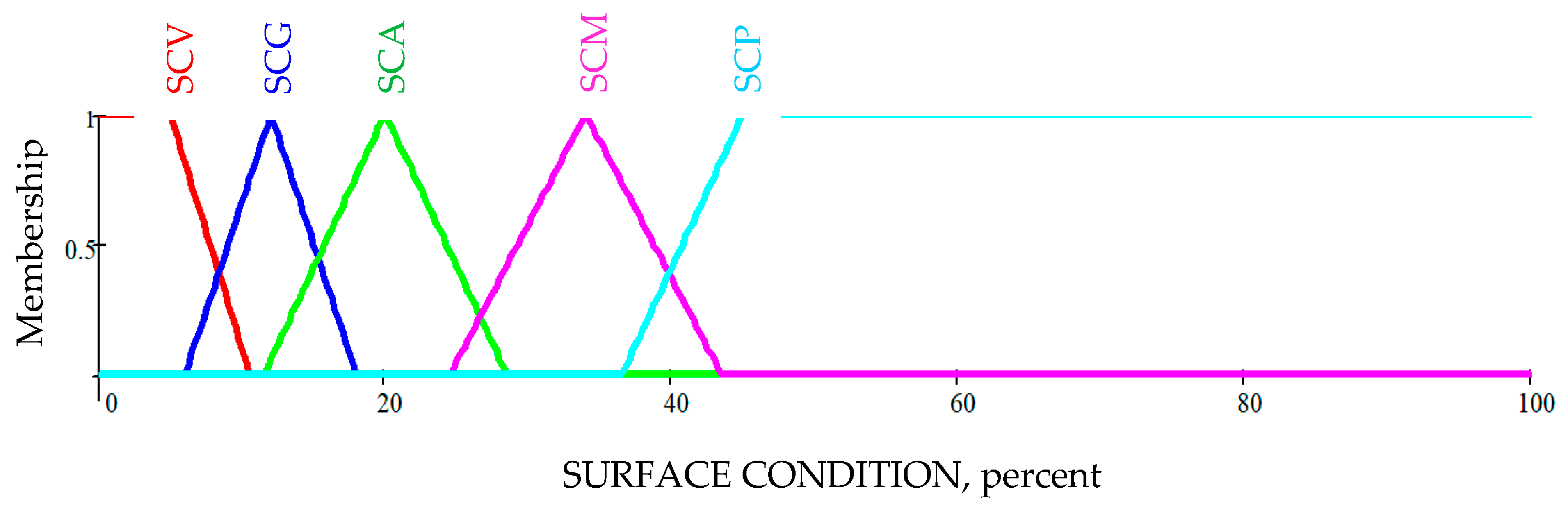
- Concrete Surface Condition (SC): It is determined based on the variance in material consistency near the surface of the deck using the near-surface dielectric permittivity measured by the GPR sensor. The surface condition is measured using estimates of near-surface dielectric permittivity. It is a function of the amplitude of the first surface reflection in the GPR data and the reference amplitude of the first surface reflection over a metal plate.
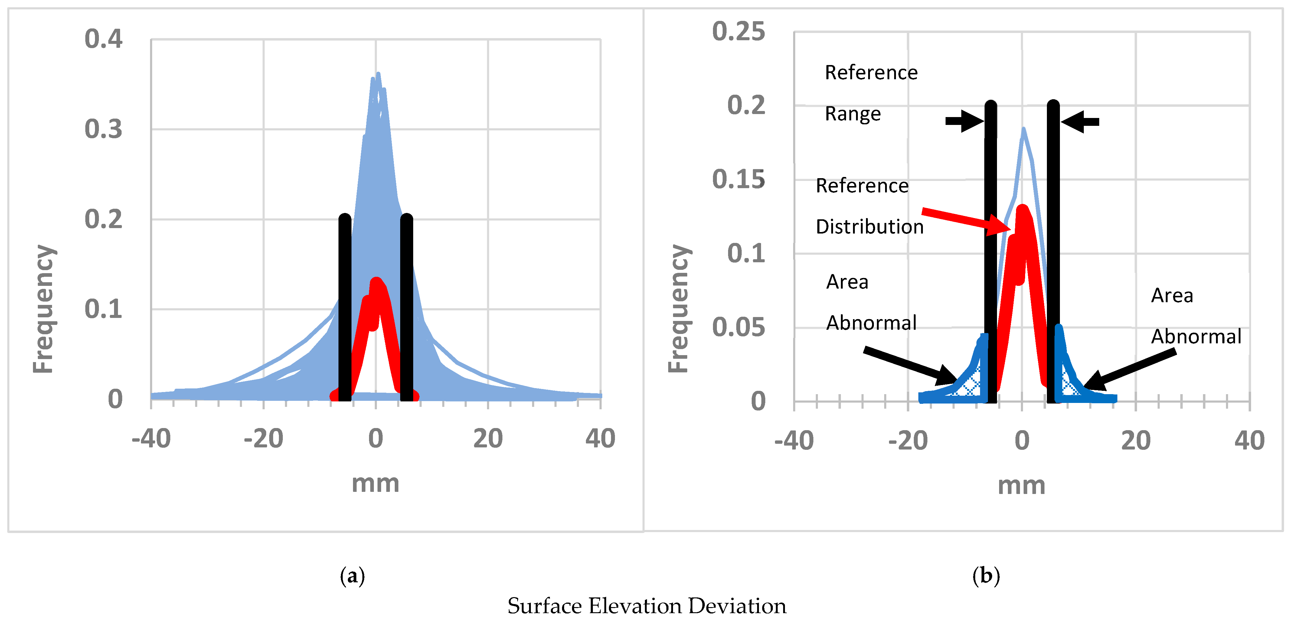
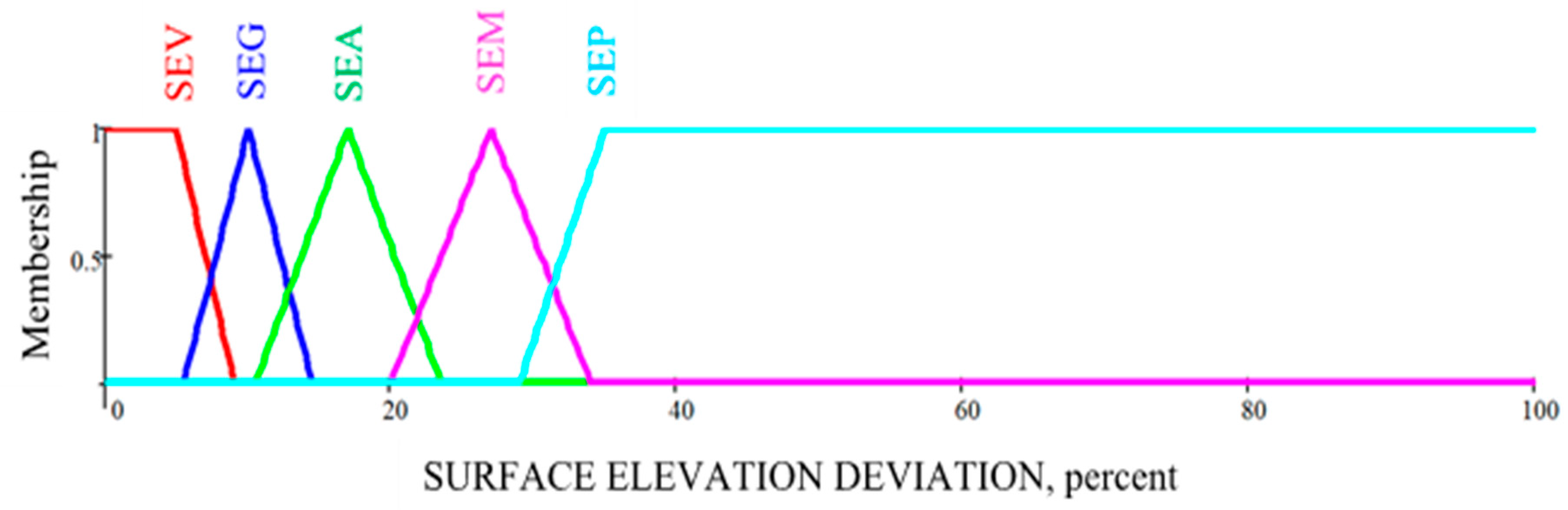
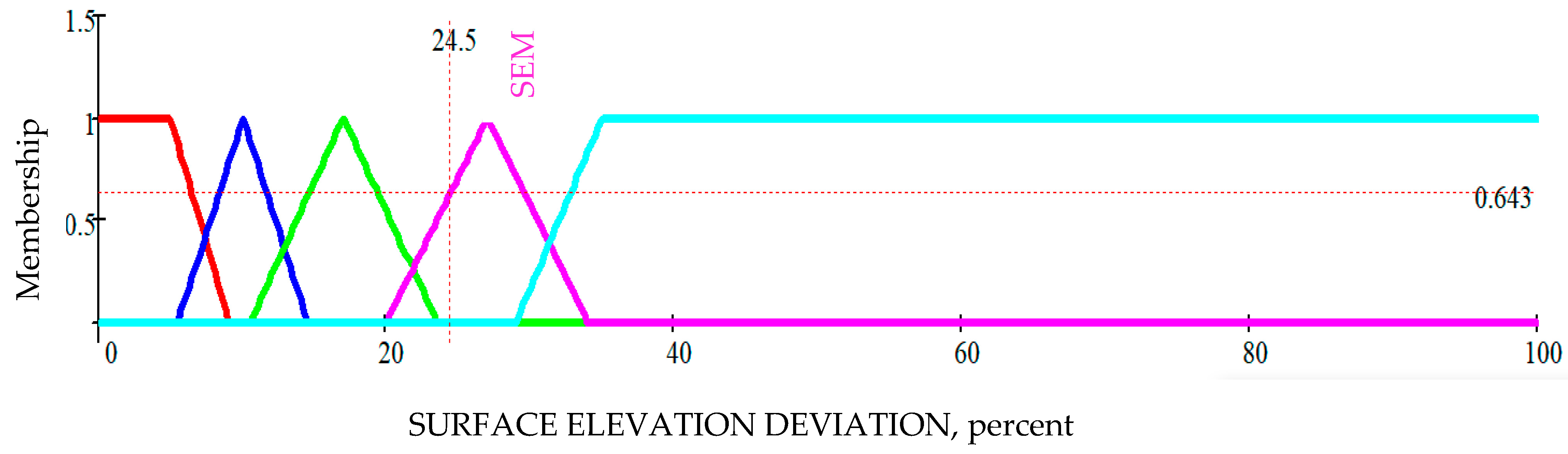
- Surface Elevation (SE): It is determined based on the vertical deviation from the surface of the deck in centimeters. Depressions (e.g., potholes, cracks) have negative surface elevations, and protrusions (e.g., bumps, overfilled patches) are positive. The vertical distance between the GPR antenna and the surface of the deck is estimated using the first surface reflection. The estimates are calibrated using the common-mid-point method. The surface elevation is computed as a reference height of the GPR antenna with respect to the surface of the deck minus the calibrated vertical distances.
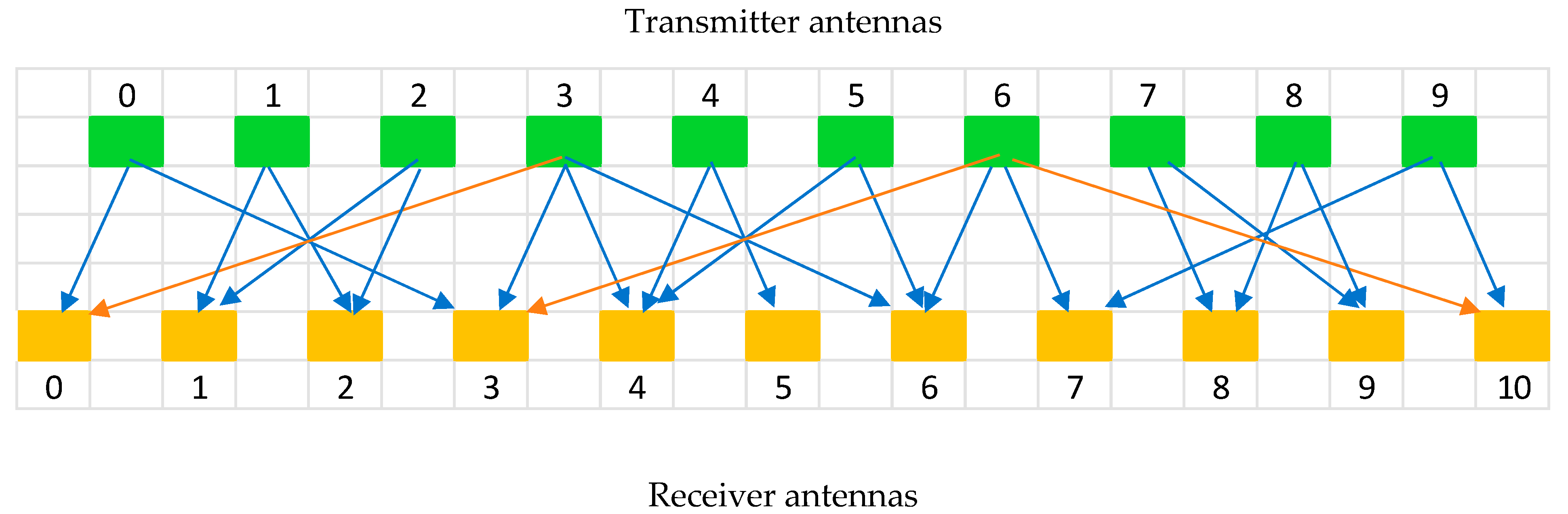
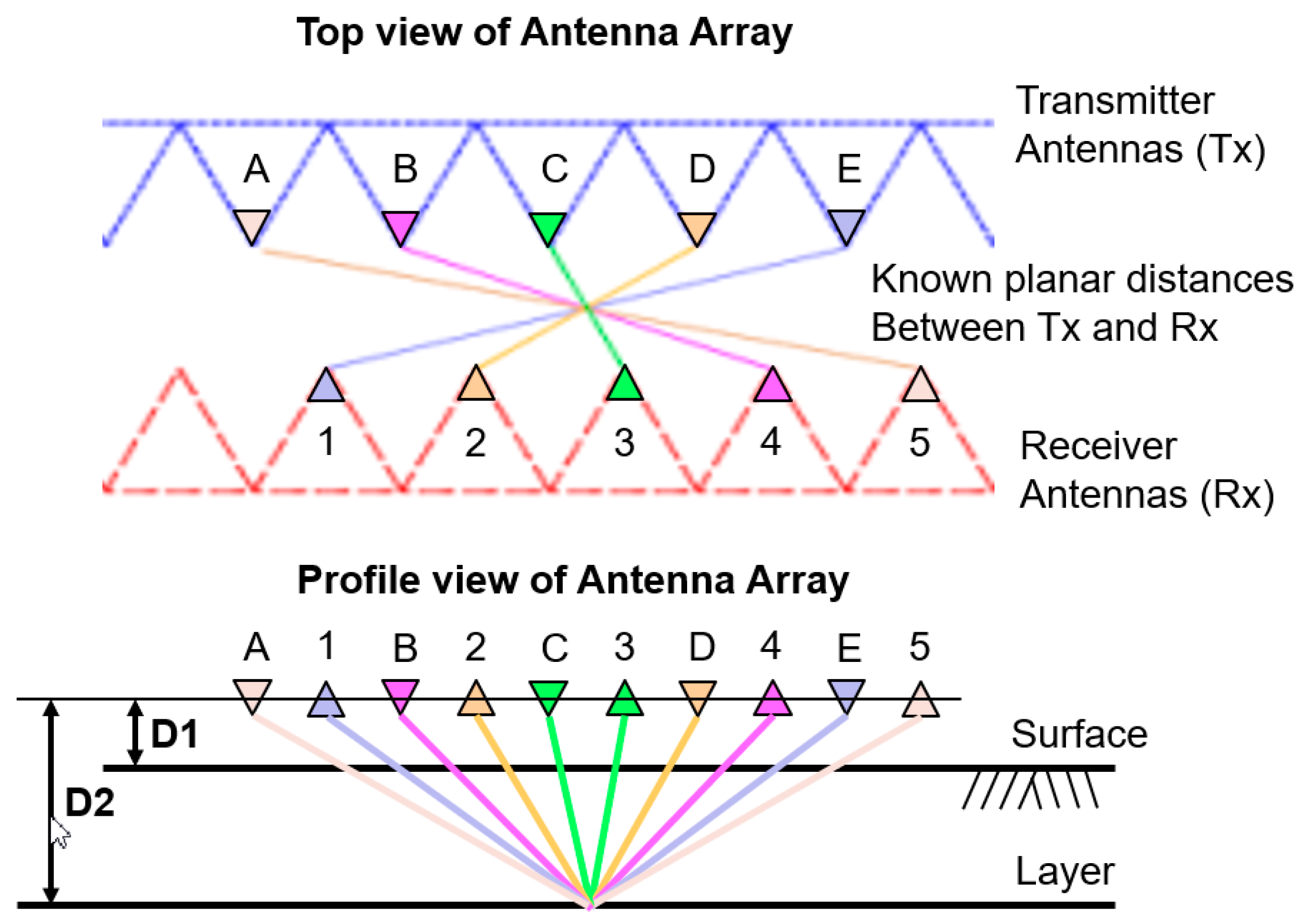
- Overlay Thickness (OT): When an HMA or concrete overlay is detected during the pre-processing of the GPR data, its thickness is estimated between the surface and the overlay/concrete-deck interface feature in the GPR measurement. The overlay thickness is reported in centimeters. The thickness of the overlay is estimated as the vertical distance between the surface and the overlay/concrete-deck interface. The estimates of thickness are calibrated using the common-mid-point (CMP) method based on geometric triangulation. Figure 5 shows an example of five lateral offsets of five different transmitter-receiver pairs. Note that all five lines cross at a common midpoint. The distance D2 is estimated using the five measurements, knowing the five lateral offsets. The thickness of the overlay is D2-D1, where D1 is estimated using a similar triangulation.
- Overlay Condition (OC): When there is an HMA or concrete overlay detected during the pre-processing of the GPR data, its condition is estimated using the dielectric permittivity near the overlay/concrete-deck interface feature in the GPR measurement and the signal strength of the GPR reflection at the interface. The overlay condition is a dimensionless parameter ranging from 1 (best) to 10 (worst). The condition of the overlay is determined using an estimate of the dielectric permittivity and signal strength of the GPR reflection at/near the overlay/concrete-deck interface. The estimates are computed and calibrated using the common-mid-point method.
- Top Steel Cover (TC): It is determined between the surface and the top steel mat features in the GPR measurement. The top steel cover is reported in centimeters and is estimated as the vertical distance between the surface and the top-steel mat interfaces. The estimates are computed and calibrated using the common-mid-point method.
- Above Steel Condition (TSC): It is determined using the dielectric permittivity near the top steel mat interface feature in the GPR measurement and the signal strength of the GPR reflection at the interface. It is a dimensionless parameter ranging from 1 (best) to 10 (worst). The condition of the top steel mat is determined using an estimate of the dielectric permittivity and signal strength of the GPR reflection at/near the top-steel mat interface, at and between the rebars. The estimates are computed and calibrated using the common-mid-point method.
- Top Steel Condition (ASC): It is estimated using the dielectric permittivity at the top steel mat interface feature in the GPR measurement and the signal strength of the GPR reflection at the interface. The top steel condition is a dimensionless parameter ranging from 1 (best) to 10 (worst). The estimates are computed and calibrated using the common-mid-point method.
- Below Steel Condition (BSC): This is estimated using the dielectric permittivity near the bottom steel mat interface feature in the GPR measurement and the signal strength of the GPR reflection at the interface. The bottom steel condition is a dimensionless parameter ranging from 1 (best) to 10 (worst). The estimates are computed and calibrated using the common-mid-point method.
- Deck Thickness (DT): It is determined between the surface and the bottom of the deck interface feature in the GPR measurement. The thickness is reported in centimeters. The estimates are calibrated using the common-mid-point method.
- Bottom Steel Cover (BC): It is determined as the vertical distance between the bottom of the deck and the bottom steel mat interface in the GPR measurement. The estimates are computed and calibrated using the common-mid-point method.
2. Fuzzy Sets Condition Rating Modeling
2.1. Fuzzy Sets Architecture
2.2. Fuzzy Sets and NBI Condition Rating Scale
3. Example Results and Discussion
4. Summary and Conclusions
Author Contributions
Funding
Data Availability Statement
Acknowledgments
Conflicts of Interest
References
- FHWA, Bridge Replacement Unit Cost 2020. Available online: https://www.fhwa.dot.gov/bridge/nbi/sd2020.cfm (accessed on 7 April 2022).
- Hu, D.; Li, S.; Ma, Z.J.; Huang, B. Concrete Bridge Deck Deterioration Assessment Using Ground Penetrating Radar; Tennessee DOT RES 2019-17; Department of Civil and Environmental Engineering, The University of Tennessee: Knoxville, TN, USA, 2021. [Google Scholar]
- Sun, H.; Pashoutani, S.; Zhu, J. Nondestructive evaluation of concrete bridge decks with automated acoustic scanning system and ground penetrating radar. Sensors 2018, 18, 1955. [Google Scholar] [CrossRef] [PubMed]
- Abu Dabous, S.; Yaghi, S.; Alkass, S.; Moselhi, O. Concrete bridge deck condition assessment using IR Thermography and Ground Penetrating Radar technologies. Autom. Constr. 2017, 81, 340–354. [Google Scholar] [CrossRef]
- Varnavina, A.V.; Sneed, L.H.; Khamzin, A.K.; Torgashov, E.V.; Anderson, N.L. An attempt to describe a relationship between concrete deterioration quantities and bridge deck condition assessment techniques. J. Appl. Geophys. 2017, 142, 38–48. [Google Scholar] [CrossRef]
- Kashif Ur Rehman, S.; Ibrahim, Z.; Memon, S.A.; Jameel, M. Nondestructive test methods for concrete bridges: A review. Constr. Build. Mater. 2016, 107, 58–86. [Google Scholar] [CrossRef]
- Goulias, D.; Cafiso, S.; Di Graziano, A.; Saremi, S.; Currao, V. Condition Assessment of Bridge Decks through Ground Penetration Radar in Bridge Management Systems. ASCE J. Perform. Constr. Facil. 2020, 34, 04020100. [Google Scholar] [CrossRef]
- Dix, C.H. Seismic velocities from surface measurements. Geophysics 1955, 20, 68–86. [Google Scholar] [CrossRef]
- Kee, S.-H.; Fetrat, F.; Gucunski, N. Advanced Signal Interpretation Algorithm for Automated Impact Echo Testing System: Application to Concrete Bridge Decks. In Proceedings of the 91th Annual Transportation Board Meeting, Washington, DC, USA, 22–26 January 2012. [Google Scholar]
- Gucunski, N.; Romero, F.; Kruschwitz, S.; Feldmann, R.; Parvardeh, H. Comprehensive Bridge Deck Deterioration Mapping of Nine Bridges by Nondestructive Evaluation Technologies; Dept. of Transportation: Ames, IA, USA, 2011. [Google Scholar]
- Gucunski, N.; Imani, A.; Romero, F.; Nazarioan, S.; Yuan, D.; Wiggenhauser, H.; Shokouhi, P.; Taffe, A.; Kutrubes, D. Nondestructive Testing to Identify Concrete Bridge Deck Deterioration; SHRP S2-R06A-RR-1; Transportation Research Board: Washington, DC, USA, 2013. [Google Scholar]
- Abouhamad, M.; Dawood, T.; Jabri, A.; Alsharqawi, M.; Zayed, T. Corrosiveness mapping of bridge decks using image-based analysis of GPR data. Autom. Constr. 2017, 80, 104–117. [Google Scholar] [CrossRef]
- Varnavina, A.V.; Khamzin, A.K.; Torgashov, E.V.; Sneed, L.H.; Goodwin, B.T.; Anderson, N.L. Data acquisition and processing parameters for concrete bridge deck condition assessment using ground-coupled ground penetrating radar: Some considerations. J. Appl. Geophys. 2015, 114, 123–133. [Google Scholar] [CrossRef]
- Alani, A.M.; Aboutalebi, M.; Kilic, G. Applications of ground penetrating radar (GPR) in bridge deck monitoring and assessment. J. Appl. Geophys. 2013, 97, 45–54. [Google Scholar] [CrossRef]
- Sultan, A.A.; Washer, G.A. Reliability Analysis of Ground-Penetrating Radar for the Detection of Subsurface Delamination. J. Bridg. Eng. 2018, 23, 04017131. [Google Scholar] [CrossRef]
- Wang, Z.W.; Zhou, M.; Slabaugh, G.G.; Zhai, J.; Fang, T. Automatic detection of bridge deck condition from ground penetrating radar images. IEEE Trans. Autom. Sci. Eng. 2011, 8, 633–640. [Google Scholar] [CrossRef]
- Barnes, C.L.; Trottier, J.-F. Effectiveness of Ground Penetrating Radar in Predicting Deck Repair Quantities. J. Infrastruct. Syst. 2004, 10, 69–76. [Google Scholar] [CrossRef]
- Al-Qadi, I.; Leng, Z.; Larkin, A. In-Place Hot Mix Asphalt Density Estimation Using Ground Penetrating Radar; ICT Report No. 11-096; University of Illinois: Urbana, Champaign, 2011. [Google Scholar]
- Scullion, T.; Chen, Y. Using Ground-Penetrating Radar for Real-Time Quality Control Measurements on New HMA Surfaces; Research Report 1702-5; Texas Transportation Institute, Texas A&M University: College Station, TX, USA, 1999. [Google Scholar]
- Saarenketo, T. Using Ground-Penetrating Radar and Dielectric Probe Measurements in Pavement Density Quality Control; Transportation Research Record 1575, TRB; National Research Council: Washington, DC, USA, 1997; pp. 34–41. [Google Scholar]
- Maser, K.R.; Scullion, T. Automated Detection of Pavement Layer Thicknesses and Subsurface Moisture Using Ground Penetrating Radar; Final Report; Texas Transportation Institute: College Station, TX, USA, 1990. [Google Scholar]
- Liu, Z.; Gu, X.; Chen, J.; Wang, D.; Chen, Y.; Wang, L. Automatic recognition of pavement cracks from combined GPR B-scan and C-scan images using multiscale feature fusion deep neural networks. Autom. Constr. 2023, 146, 104698. [Google Scholar] [CrossRef]
- Liu, Z.; Yeoh, J.; Gu, X.; Chen, J.; Dong, Q.; Chen, Y.; Wu, W.; Wang, L.; Wang, D. Automatic pixel-level detection of vertical cracks in asphalt pavement based on GPR investigation and improved mask R-CNN. Autom. Constr. 2023, 146, 104689. [Google Scholar] [CrossRef]
- Omar, T.; Nehdi, M.L.; Zayed, T. Integrated Condition Rating Model for Reinforced Concrete Bridge Decks. J. Perform. Constr. Facil. 2017, 31. [Google Scholar] [CrossRef]
- Gagarin, N.; Mekemson, J. Non-Destructive Testing of Pavements for Location and Evaluation of In-Roadway Sensor Installations; Small Business Innovation Research (SBIR) Phase IIb, Program Office, John, A. Volpe National Transportation Systems Center (Volpe Center), U.S. Department of Transportation (DOT): Cambridge, MA, USA, 2011. [Google Scholar]
- Starodub, Inc. Travel Way Measurement System. Patent No. US8306747 B1, 6 November 2012. [Google Scholar]
- Goulias, D.; Gagarin, N. Effective Implementation of Ground Penetrating Radar (GPR) for Condition Assessment & Monitoring of Critical Infrastructure Components of Bridges and Highways; SBIR, Phase 2; Maryland SHA: Hanover, MD, USA, 2016. [Google Scholar]
- Goulias, D.; Gagarin, N.; Mekemson, J. Deployment of Step-Frequency (SF) Ground-Penetrating-Radar (GPR) Array System for Condition Assessment of Bridge Decks. In Proceedings of the NDE/NDT for Highways and Bridges: Structural Materials Technology (SMT) 2016, Portland, OR, USA, 29–31 August 2016. [Google Scholar]
- Gagarin, N.; Goulias, D.; Mekemson, J.; Cutts, R.; Andrews, J. Development of a Novel Methodology for Assessing Bridge Deck Conditions Using Step Frequency Antenna Array Ground Penetrating Radar. ASCE J. Perform. Constr. Facil. J. 2020, 34. [Google Scholar] [CrossRef]
- Goulias, D. Optimizing Field Data Collection & Developing Advanced Ground Penetration Radar (GPR) Processing Modules, Phase 3; Final Research Report, #UM4-54; Maryland State Highway Administration: Hanover, MD, USA, 2020. [Google Scholar]
- Zadeh, L.A. Fuzzy Sets. Inf. Control. 1965, 8, 338–353. [Google Scholar] [CrossRef]
- FHWA, National Bridge Inventory, NBI, Updated 5 May 2021. Available online: https://www.fhwa.dot.gov/bridge/nbi.cfm (accessed on 29 January 2023).
- Saremi, S.; Goulias, D.; Zhao, Y. Alternative Sequence Classification Neural Networks for Bridge Deck Condition Rating. ASCE J. Perform. Constr. Facil. 2023, 37. [Google Scholar] [CrossRef]


| Rating | Definition | Comments |
|---|---|---|
| 9 | excellent condition | |
| 8 | very good condition | no problems noted; |
| 7 | good condition | some minor problems; |
| 6 | satisfactory condition | structural elements show some minor deterioration; |
| 5 | fair condition | all primary structural elements are sound but may have minor section loss, cracking, spalling, or scour; |
| 4 | poor condition | advanced section loss, deterioration, spalling, or scour; |
| 3 | serious condition | loss of section, deterioration of primary structural elements. Fatigue cracks in steel or shear cracks in concrete may be present; |
| 2 | critical condition | advanced deterioration of primary structural elements. Fatigue cracks in steel or shear cracks in concrete may be present, or scouring may have removed substructure support. Unless closely monitored, it may be necessary to close the bridge until corrective action is taken; |
| 1 | “imminent” failure condition | major deterioration or section loss present in critical structural components or obvious vertical or horizontal movement affecting structure stability. The bridge is closed to traffic, but corrective action may put it back in light service; and |
| 0 | failed condition | out of service and beyond corrective action. |
| Function | RI | RC | RS | RP | RF | RO | RG | RV | RE |
|---|---|---|---|---|---|---|---|---|---|
| Center | 1 | 2 | 3 | 4 | 5 | 6 | 7 | 8 | 9 |
| Width | 2 | 2 | 2 | 2 | 1.5 | 1.5 | 1.5 | 1.5 | 2 |
| Description | Imminent Failure | Critical | Serious | Poor | Fair | Satisfactory | Good | Very Good | Excellent |
| Function | SCV | SCG | SCA | SCM | SCP |
|---|---|---|---|---|---|
| Center | 5 | 12 | 20 | 34 | 45 |
| Width | 11 | 12 | 17 | 19 | 17 |
| Description | Very Good | Good | Acceptable | Marginal | Poor |
| Function | SEV | SEG | SEA | SEM | SEP |
|---|---|---|---|---|---|
| Center | 5 | 10 | 17 | 27 | 35 |
| Width | 8 | 9 | 13 | 14 | 12 |
| Description | Very Good | Good | Acceptable | Marginal | Poor |
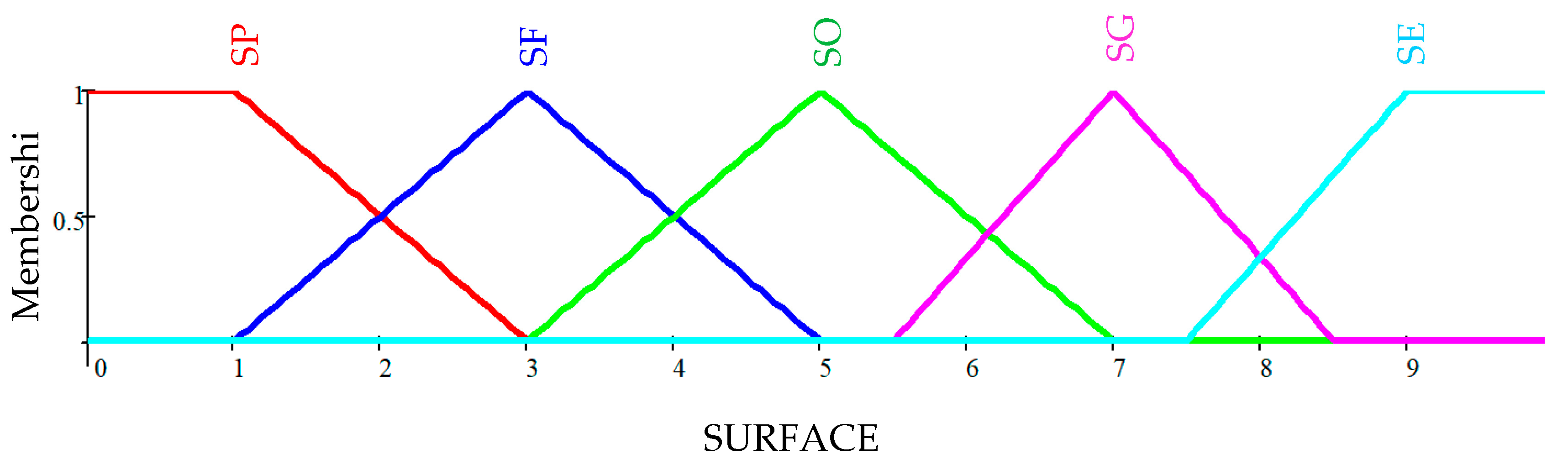
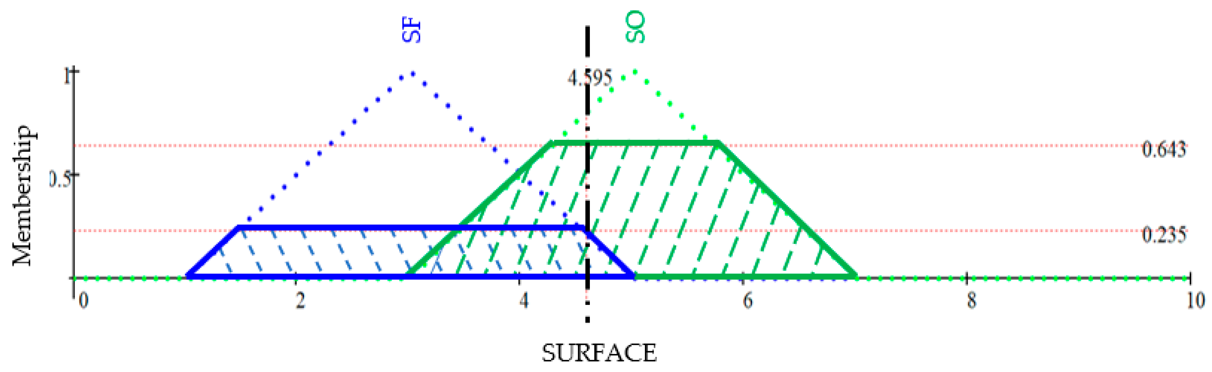
| Function | SP | SF | SO | SG | SE |
|---|---|---|---|---|---|
| Center | 1 | 3 | 5 | 7 | 9 |
| Width | 4 | 4 | 4 | 3 | 3 |
| Description | Poor Surface | Fair Surface | Satisfactory Surface | Good Surface | Excellent Surface |
| SEV | SEG | SEA | SEM | SEP | |
|---|---|---|---|---|---|
| SCV | SE | SG | SO | SO | SF |
| SCG | SE | SG | SO | SO | SF |
| SCA | SG | SG | SO | SF | SP |
| SCM | SG | SO | SO | SF | SP |
| SCP | SO | SO | SF | SP | SP |
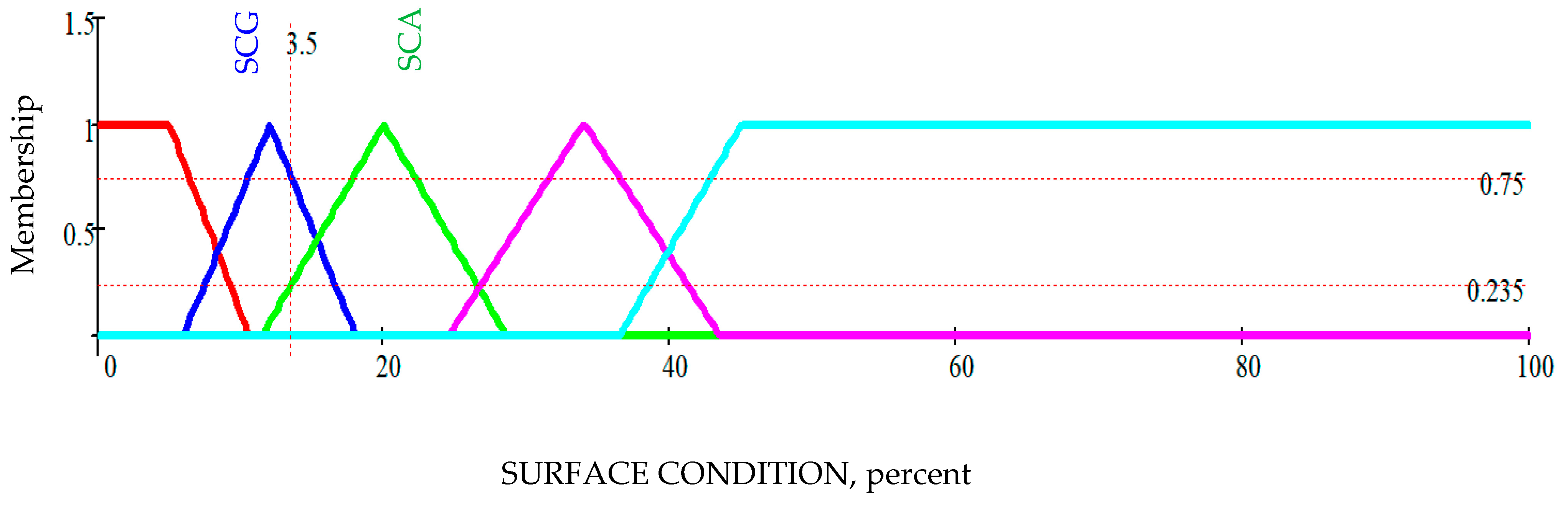
| Case 1: (SCG, SEM) | SEV | SEG | SEA | SEM/0.643 | SEP |
| SCV | SE | SG | SO | SO | SF |
| SCG/0.75 | SE | SG | SO | SO/0.643 | SF |
| SCA | SG | SG | SO | SF | SP |
| SCM | SG | SO | SO | SF | SP |
| SCP | SO | SO | SF | SP | SP |
| Case 2: (SCA, SEM) | SEV | SEG | SEA | SEM/0.643 | SEP |
| SCV | SE | SG | SO | SO | SF |
| SCG | SE | SG | SO | SO | SF |
| SCA/0.235 | SG | SG | SO | SF/0.235 | SP |
| SCM | SG | SO | SO | SF | SP |
| SCP | SO | SO | SF | SP | SP |
| Description | Span Number | Overall Score | Overall Variability | CSC Surface Condition | SED Surface Elevation Deviation | ||
|---|---|---|---|---|---|---|---|
| % Area Abnormal | Variability | % Area Abnormal | Variability | ||||
| Structure 1 | 0 | 4.374 | 2.437 | 3.016 | 4.969 | 31.864 | 1.031 |
| Structure 1 Span | 1 | 4.371 | 1.516 | 7.987 | 4.210 | 32.242 | 1.132 |
| Structure 1 Span | 2 | 4.000 | 1.181 | 2.980 | 1.027 | 35.908 | 1.049 |
| Structure 1 Span | 3 | 4.345 | 1.122 | 0.897 | 1.027 | 32.151 | 1.027 |
| Structure 1 Span | 4 | 5.000 | 1.091 | 1.749 | 1.300 | 24.135 | 1.048 |
| Structure 2 | 0 | 3.000 | 2.156 | 31.768 | 3.000 | 38.892 | 1.031 |
| Structure 2 Span | 1 | 3.000 | 1.187 | 28.409 | 1.027 | 37.235 | 1.027 |
| Structure 2 Span | 2 | 3.000 | 1.053 | 30.888 | 1.027 | 39.395 | 1.048 |
| Structure 2 Span | 3 | 3.000 | 1.568 | 28.696 | 4.380 | 38.431 | 1.027 |
| Structure 2 Span | 4 | 3.000 | 1.200 | 44.706 | 1.027 | 41.407 | 1.048 |
| Structure | Example 1 | Example 2 | Global | ||||||
| Span | All | 1 | 2 | 3 | All | 1 | 2 | 3 | Median |
| Overall Score | 5.00 | 5.00 | 5.00 | 5.00 | 3.00 | 3.00 | 3.00 | 3.00 | 5.00 |
| Surface Condition | 7.4 | 5.4 | 8.4 | 7.0 | 28.9 | 34.4 | 26.5 | 28.1 | 14.6 |
| Surface Elevation Deviation | 21.2 | 19.5 | 19.9 | 25.5 | 36.1 | 38.5 | 34.8 | 36.2 | 15.5 |
| Concrete Cover Deviation | 13.0 | 10.2 | 16.4 | 8.2 | 18.9 | 13.1 | 20.7 | 21.1 | 17.6 |
| Bottom Surface Deviation | 21.1 | 17.2 | 21.8 | 23.0 | 10.6 | 10.3 | 10.9 | 10.3 | 28.4 |
| Condition at Top Rebar | 23.9 | 19.6 | 26.0 | 22.8 | 9.4 | 10.2 | 9.4 | 8.8 | 31.4 |
| Condition Above Top Rebar | 26.2 | 24.1 | 27.6 | 25.0 | 7.2 | 7.5 | 7.2 | 6.8 | 26.0 |
| Condition Between Rebar | 6.4 | 6.2 | 6.6 | 6.1 | 13.3 | 12.6 | 13.2 | 14.1 | 9.6 |
Disclaimer/Publisher’s Note: The statements, opinions and data contained in all publications are solely those of the individual author(s) and contributor(s) and not of MDPI and/or the editor(s). MDPI and/or the editor(s) disclaim responsibility for any injury to people or property resulting from any ideas, methods, instructions or products referred to in the content. |
© 2023 by the authors. Licensee MDPI, Basel, Switzerland. This article is an open access article distributed under the terms and conditions of the Creative Commons Attribution (CC BY) license (https://creativecommons.org/licenses/by/4.0/).
Share and Cite
Gagarin, N.; Goulias, D.; Mekemson, J. Condition Rating of Bridge Decks with Fuzzy Sets Modeling for SF-GPR Surveys. Remote Sens. 2023, 15, 3631. https://doi.org/10.3390/rs15143631
Gagarin N, Goulias D, Mekemson J. Condition Rating of Bridge Decks with Fuzzy Sets Modeling for SF-GPR Surveys. Remote Sensing. 2023; 15(14):3631. https://doi.org/10.3390/rs15143631
Chicago/Turabian StyleGagarin, Nicolas, Dimitrios Goulias, and James Mekemson. 2023. "Condition Rating of Bridge Decks with Fuzzy Sets Modeling for SF-GPR Surveys" Remote Sensing 15, no. 14: 3631. https://doi.org/10.3390/rs15143631
APA StyleGagarin, N., Goulias, D., & Mekemson, J. (2023). Condition Rating of Bridge Decks with Fuzzy Sets Modeling for SF-GPR Surveys. Remote Sensing, 15(14), 3631. https://doi.org/10.3390/rs15143631