Abstract
With the increasing utilization of location information, attempts to improve the safety of absolute positioning coordinates, which have depended on global navigation satellite systems (GNSSs), such as the Global Positioning System (GPS), are underway. Among these, enhanced long range navigation (eLoran) is the most technically developed system. In Korea, related technologies have been developed since 2016, and a testbed for eLoran performance evaluation, which is currently in operation as a pilot service, was completed in 2021. We analyze the position accuracy of the eLoran pilot service to use it as an alternative when GNSS usage is challenging within Korea’s eLoran testbed. We evaluated the accuracy of the absolute position using the eLoran system by sailing up to 160 km away from the Incheon testbed transmitter according to four navigation stages (inland waterway, port approach, coastal, and ocean) classified by the International Maritime Organization (IMO). To validate the eLoran positioning performance in which an additional secondary factor (ASF) map is not provided, we propose a differential GPS (DGPS) position-based ASF estimation technique. Based on this study, Korea’s eLoran system can calculate the absolute position with an accuracy of approximately 15 m with 95% probability at the port-approach stage.
1. Introduction
Reliable positioning, navigation, and timing (PNT) information are becoming increasingly crucial in various applications [1,2,3,4]. In particular, the PNT information, which is currently the most widely used technology, is essential for autonomous driving. The most representative PNT infrastructures include global navigation satellite systems (GNSSs), enabling users to receive radio signals from satellites located approximately 20,000 km above the Earth’s surface and calculate distances from the satellites to determine their position and time. Because the GNSS can be used anywhere in an open-sky environment, numerous location-based services rely on GNSS [5,6].
To obtain more reliable PNT information through the GNSS, a considerably number of signals should be received from the satellites. Therefore, more countries are continuously expanding their GNSSs and making continuous efforts to increase their efficiency by utilizing more frequency signals [7,8,9]. Currently, GNSSs include the Global Positioning System (GPS) operated by the United States, Galileo by the European Union, GLONASS by Russia, and BeiDou by China. The Republic of Korea is planning to establish its own satellite navigation system for use in areas near the Korean peninsula through the Korean positioning system project that commenced in 2022 [10].
However, GNSS signals are vulnerable to intentional or unintentional radio interference because of their extremely low strength and their signal structure being open to all. For instance, the use of small GPS jammers by truck drivers to evade tracking by the company could cause havoc at key national facilities, such as airports. Even with regard to military conflict, it occurs in a more frequent and advanced manner [11,12]. GNSS jamming and/or spoofing have been frequently reported in Europe, East Asia, and the Middle East. According to the European Union Aviation Safety Agency (EASA), since 24 February 2022, GNSS spoofing and jamming have intensified in four major geographical areas, including the Black Sea [13].
International organizations, such as the International Maritime Organization (IMO) and the International Civil Aviation Organization, recommend the use of terrestrial navigation systems to compensate for vulnerabilities in GNSSs. In the marine field, the expected damage is enormous in situations where GNSSs do not work, owing to the high dependence on PNT information on GNSSs [14]. Therefore, the development of a navigation system based on ground radio signals that can be used at sea, such as the enhanced long range navigation (eLoran) and ranging mode (R-Mode), is underway [15,16,17,18,19].
Among emerging terrestrial navigation systems for maritime areas, the eLoran system has the most technically complete and close-to-full operational capability. The U.S participated in the modernization of Loran-C to validate the feasibility of eLoran. Moreover, the U.K implemented the initial operational capability (IOC) of the eLoran system in conjunction with the Northwest European Loran-C system and proposed a plan to establish a new transmission station through the MarRINav project [20]. In South Korea, since June 2021, the eLoran pilot service has operated near two major ports in the West Sea [21].
As eLoran signals propagate along the surface, various propagation delays occur, depending on the propagation path medium. The propagation delay that occurs according to terrain or altitude remains unchanged with time and is called the spatial additional secondary factor (ASF), whereas the propagation delay that depends on weather or season and changes over time is called the temporal ASF. The spatial ASF is measured in advance at each position within the eLoran service area and converted into a map-type database, enabling the user to calculate the corrected position [22,23].
Currently, South Korea’s eLoran system is designed to correct each error accurately such that users can calculate their location within 20 m of accuracy near both ports. An eLoran differential station collects signals in real time near the port to monitor changes in the range measurement and generate real-time ASF correction. In addition, eLoran service providers use real-time ASF correction to measure the spatial ASF at each location within a 30 km radius and store it in the form of a grid map. Finally, the user can calculate the exact position using both the spatial ASF map and ASF correction received in real time.
The correlation of the real-time ASF correction between the eLoran differential station and the user location decreases as the distance from the eLoran differential station increases, rendering the accurate measurement of the spatial ASF challenging. Therefore, a spatial ASF map is not provided outside the 30 km radius of the reference station; thus, an eLoran receiver estimates its position with the same positioning process as the existing Loran-C. Although Loran-C has a proven positioning accuracy of approximately 460 m [24], the position error can be as high as several kilometers depending on the dilution of precision, which is the geometric arrangement between the transmitters and user.
This study aims to investigate the positioning performance of an eLoran receiver in four navigation stages classified by the IMO (inland waterways, harbor approaches, coastal waters, and oceans). For this purpose, we collected data from a long-term voyage using a ship equipped with an eLoran receiver and a differential GPS (DGPS) receiver. To evaluate the positioning performance in areas where ASF maps are unavailable, we propose a method for estimating ASF based on DGPS positions. This method proved valuable for assessing and validating the performance of eLoran positioning during the experiment.
The remainder of this paper is organized as follows. Section 2 describes recent updates to the Korean eLoran system, including eLoran transmitters and eLoran differential stations. Section 3 describes the experimental equipment and methods used to realize the objectives of this study. In Section 4, we analyze the results obtained by installing the experimental equipment on a real ship and sailing it for a prolonged period. Finally, the findings are summarized in Section 5.
2. Recent Updates on the Korean eLoran System
2.1. eLoran Transmitters
2.1.1. Reference Time Synchronization
The main difference between eLoran and Loran-C is the timing of the signal transmission. In previous Loran-C systems, the secondary transmitter emitted its signal based on the time of arrival (TOA) of the master transmitter signal using the system area monitor method. However, with the implementation of the eLoran system, all the transmitters are synchronized to the Loran time based on the GPS time and leap seconds. This change overcomes the limitations of the Loran-C system in which the signal transmission time is inaccurate owing to changes in the propagation time caused by environmental changes in the baseline distance between the master and secondary transmitters. Currently, in Korea’s eLoran system, all transmitters are synchronized to the Loran system time within 10 ns using high-performance cesium atomic clocks and GNSS-based timing receivers.
2.1.2. eLoran Data Channel
The eLoran data channel (LDC) is a significant advancement in eLoran technology [25]. Two main methods are used to add LDC. The Eurofix method, which modulates the data by transmitting the 3rd to 8th pulse signals not used for navigation at +1 µs, 0 µs, or −1 µs from the reference time and the 9th pulse modulation method, which transmits an additional pulse for data transmission and modulates it according to its transmission time. The United States attempted to transmit LDC using the 9th pulse modulation method, whereas the UK used the Eurofix method during the IOC [26]. In Korea, the Eurofix method can provide LDC over a wider range based on an analysis of signals received from the Incheon testbed transmitter at the Incheon and Pyeongtaek differential eLoran stations in 2022 [27].
2.1.3. Effective Power Radiation
The coverage of the eLoran service can be influenced by the effective radiated power (ERP) of the transmitter. ERP refers to the actual power of the emitted signal, considering the radiation efficiency based on the antenna type and height. Top-loaded monopoles (TLM) are the most widely used antenna type worldwide and are known for their high radiation efficiency at the same height. In Korea’s Pohang, Gwangju, and Incheon testbeds, TLM antennas with heights of 137, 122, and 35 m were used for all eLoran transmitters, with ERPs of 150 kW, 50 kW, and 800 W for the Pohang, Gwangju, and Incheon testbeds, respectively. Following transmission, the signal naturally weakens with distance and is influenced by various noise sources, such as atmospheric and receiver noise, resulting in a signal-to-noise ratio (SNR) measured by the receiver. A study on range estimation accuracy simulation based on signals transmitted from the Pohang and Gwangju transmitters was conducted and published in 2021 [28]. The Incheon testbed transmitter was expected to operate with an ERP of 8 kW when relocated to Socheong Island to cover a wider area.
2.2. Differential eLoran Station
2.2.1. eLoran Signal Propagation Delay Owing to Environmental Influence
As eLoran signals propagate along the ground, they are influenced by several factors in the propagation environment, such as terrain and ground characteristics. These factors can cause delays in signal propagation and are categorized as primary factor (PF), secondary factor (SF), and ASF. PF and SF are caused by signals propagating through the atmosphere and along the sea surface, respectively, whereas ASF is caused by other topographical features. In 1977, Brunavs published a model to predict the amount of delay caused by PF and SF as a function of the propagation path length. Various studies on model prediction, such as BALOR, have been conducted for ASF [29,30,31]. However, the accurate prediction of ASF is challenging because of the influence of various environmental variables. In Korea, PF and SF delays are approximately 400–500 m, whereas ASF delays can reach 400–800 m [32].
2.2.2. Real-Time ASF Correction and Spatial ASF Map
The Korean eLoran system offers two distinct services to ensure precise positioning for its users. The first service involves real-time ASF correction, which relies on monitoring the eLoran signal in real-time at a differential eLoran station with a similar propagation environment as the user’s location. This enables tracking of signal delays, generation of correction information, and delivery to the user through the LDC (Loran Data Channel) for enhanced positioning accuracy.
The second service provides spatial ASF maps, where the eLoran service provider accurately measures the signal propagation time within the service area. Utilizing real-time ASF correction, the provider determines the time-invariant ASF, known as the spatial ASF. Representative values are then generated and presented to the user in the form of a map, with each grid interval indicating the ASF measurements. In April 2021, by utilizing ASF maps measured in December 2020 along with real-time ASF corrections from the Incheon eLoran differential stations, the service achieved a positioning accuracy of approximately 16 m [33].
3. Materials and Method
In the current state of Korean eLoran systems, although ASF maps have been produced and positioning performance has been validated in some areas, the coverage of such maps is quite limited. Moreover, the real-time ASF correction generated by the eLoran differential stations may not have a wide validity range owing to the highly variable terrain in Korea. Therefore, alternative methods of validating eLoran positioning performance in areas where ASF maps and real-time ASF corrections are unavailable should be explored.
A possible method is to utilize the mandatory DGPS receiver specified in the Korean ship safety act to estimate the ASF and use it for the eLoran position correction. DGPS-based ASF estimates can be less accurate than values from an ASF map measured using a receiver time-synchronized to the eLoran system; however, this can be mitigated by estimating the receiver clock error in position solution derivation. This section describes the experimental equipment and measurement methods used to estimate the ASF based on DGPS positions.
3.1. Equipment
The most advanced commercially available eLoran receiver is from Ursanav (North Billerica, MA, USA). The eLoran receiver must satisfy the minimum functional requirements established by the radio technical commission for maritime services (RTCM) special committee (SC)-127 [34]. These includes the ability to search for multiple group repetition intervals (GRI) and suppress cross-rate interference caused by different GRI signals, and they include continuous wave interference mitigation capabilities to remove interference sources of continuous wave signals at particular frequencies. Furthermore, an eLoran receiver requires the pre-entry of almanac information, such as transmitter location and emission delay (ED), into memory and the ability to demodulate and decode LDC information from particular transmitters. Ursanav’s UN-151 module satisfies the minimum performance requirement of an eLoran receiver and was used during eLoran IOC tests in the U.K. Additionally, a firmware update corresponding to the configuration of the Korean eLoran system was completed.
A DGPS receiver installed onboard the vessel was used to evaluate the accuracy of the positions calculated using the eLoran system. According to Korea’s ship safety law, all vessels weighing over 20 tons must be equipped with a DGPS receiver for safe navigation. The experiment used a government vessel weighing 97 tons with an already-installed DGPS receiver. The DGPS receiver, model DSPR-1400, is a product of Samyoung ENC Co., Ltd. Busan, Korea. Although the performance specifications in the datasheet indicate a position accuracy of approximately 3 m, it provided accuracy within 1 m for almost all instances during actual use.
3.2. Experimental Site near Incheon Port
The IMO has defined the requirements of satellite navigation systems for maritime users in four phases, namely, inland waterways, harbor approaches, coastal waters, and oceans, as outlined in Resolution A.915(22). Incheon Port, among the largest ports in South Korea, was chosen as the experimental site for this study. Its maritime space is officially classified by the Korean Ministry of Oceans and Fisheries, as shown in Figure 1. By matching each classified space with the categories specified in Resolution A.915(22), the red area represents an inland waterway named Ara, the orange area represents the port area, the blue area represents the coastal area, and the remaining areas correspond to the ocean. Based on Resolution A.1046(27), radio navigation systems should achieve a positioning accuracy of 10 m with 95% probability in harbor approaches and coastal waters, and 100 m in oceans. This study validated whether the eLoran system satisfied these requirements for each phase of the voyage.
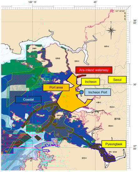
Figure 1.
Spatial management plan for the Incheon Port area, officially released by the Korean government’s Ministry of Oceans and Fisheries, centered on Incheon Port, is divided into inland waterways, port, and other coastal areas.
3.3. Methods to Determine eLoran ASF Measurements
In the UN-151 module developed by Ursanav, the receiver clock was synchronized to the UTC using UTC-related messages received through the LDC message, and the receiver output the TOA of the eLoran signal based on this synchronization. However, the TOA output by the receiver did not correspond to the literal definition of the TOA because it included the signal propagation time (), emission delay (ED) of the i-th transmitter, and receiver clock offset (). This can be mathematically expressed using Equation (1):
where i indicates the number used to identify the three eLoran transmission stations. Suppose the position of the eLoran receiver is known precisely through the DGPS receiver. In that case, can be broken down as shown in Equation (2):
is a function proposed by Brunavs, which represents the amount of additional time delay incurred when the propagation signal travels through the sea surface compared with the time consumed to propagate in vacuum. can be divided into two: time-variant () and time-invariant ASF (). Generally, eLoran users consider the real-time ASF correction received from nearby eLoran differential stations to be an , whereas the estimated value from the ASF map is regarded as an . However, in this study, we used without distinguishing between and . It is important to note that this method has certain limitations, as it may not fully account for the changes in over time. Therefore, the derived ASF values may not remain valid for extended periods. Nevertheless, this approach can be effectively used to assess the system’s performance under optimal conditions when ASF correction is implemented accurately through various methods.
Equation (3) can be obtained by rearranging the terms in Equations (1) and (2) and isolating the term.
where is the only unknown variable, represents the measured value obtained by the receiver, indicates a predetermined value stored in the receiver’s memory, indicates a calculated value based on the known coordinates of the i-th transmitter and the user’s position obtained through the DGPS receiver, and represents a function that uses as the input. Although the true value of cannot be determined, it was estimated using weighted least squares, which can accurately estimate the clock offset during positioning with eLoran signals [35].
3.4. Demonstration Method of eLoran Positioning Accuracy
To evaluate the positioning accuracy of the Korean eLoran system within the four navigation stages identified by IMO, the data from each stage-specific region were analyzed. The difference between the positions obtained solely from eLoran and the positions from the DGPS receiver was defined as the positioning error of the Korean eLoran system. The positioning errors were sorted in ascending order, and analysis was conducted on the values corresponding to the 95th percentile and the maximum value.
To comprehensively evaluate the positioning accuracy of the eLoran system in a unified manner, we conducted the experiment assuming the unavailability of both real-time ASF correction and ASF maps in all testbed regions. In order to validate the system’s performance, we employed the methodology proposed in Section 3.3. Three distinct scenarios were considered to assess the system’s performance. In the first scenario, the positioning error was determined by conducting measurements without undergoing any correction process, similar to Loran-C. The second scenario aimed to verify the system’s performance in situations where continuous access to real-time ASF correction and ASF maps during eLoran navigation was not feasible. In this case, the positioning accuracy was assessed by applying correction based on the DGPS position solely at the start of the navigation segment. In the third scenario, we examined the system’s performance under the assumption of real-time ASF correction and availability of ASF maps. Correction was performed at each interval defined by the ASF maps to verify the resulting positioning accuracy.
4. Results
4.1. Inland Waterway
The first experiment was conducted in an inland waterway called Ara, located adjacent to the Incheon Port. The Incheon testbed transmission station was installed at a location where the sea and inland waterways converge, as illustrated in Figure 2. Due to the near-field effect of the eLoran signal within a 6 km radius from the transmitter, the experiment was conducted beyond this range. The vessel completed a round trip of approximately 10 km, and the uncorrected eLoran position exhibited an error of 585.13 m at a 95% confidence level, with a maximum error of 605.36 m, when compared to the DGPS position. By estimating the ASF based on the DGPS position at the start and utilizing it to correct the position error, the error was reduced to 95.72 m at the 95% confidence level, with a maximum error of 154.3 m. Furthermore, when navigating at intervals of 500 m and 1 km and estimating the ASF based on the DGPS position to correct the position error, the 95% error levels were 39.90 m and 48.09 m, respectively, with a maximum error of 127.81 m in all cases.
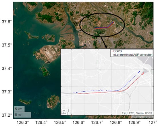
Figure 2.
Experimental site in the Ara inland waterway. Owing to the ASF caused by the propagation path of approximately 280 km from the Gwangju and Pohang transmitters, which is not shown in the figure, the eLoran position results without ASF correction show a constant offset from the DGPS position.
ASF measurements can be used to create an ASF map with regular grid spacing, and the RTCM SC-127 eLoran receiver document on minimum requirements describes how this ASF map can be used. Here, we analyze the performance when an ASF map created using bilinear interpolation is used. The 95% error level is 19.33 m and the maximum error is 127.81 m, assuming an ASF map is provided. The maximum error of 127.81 m in several cases was estimated to result from the temporary deterioration of the signal quality caused by the impact of the vehicular traffic bridge installed in the inland waterway.
4.2. Port Approach
The second experiment was conducted at a port in Incheon. According to the marine spatial management plan of the Ministry of Oceans and Fisheries of Korea (Figure 1), the port area is defined as an area within approximately 20 km from Incheon Port. The port approach phase, defined by the IMO, refers to the navigation stage within the port area. eLoran positioning data were collected and analyzed along the designated route within the port area (Figure 3). As in the previous experiment, the eLoran positioning accuracy with no correction was 1062.98 m at 95% level, and the maximum error was 1446.27 m. The 95% accuracy was 103.78 m, and the maximum error was 1377.99 m when corrected once at the start. When DGPS was used to estimate the ASF at 500 m intervals during navigation and to correct the eLoran position, the 95% accuracy was 26.06 m, and the maximum error was 1318.04 m. The 95% accuracy was 43.75 m, and the maximum error was 1323.05 m if corrected in intervals of 1 km. The user was expected to have an accuracy of 18.84 m at the 95% level, assuming the ASF map was distributed based on the measured ASF at each epoch. As in the previous experiment, the maximum error was large, approximately 1.3 km, and this error occurred when navigating under the Incheon Bridge that connects the Incheon Airport with the inland area.
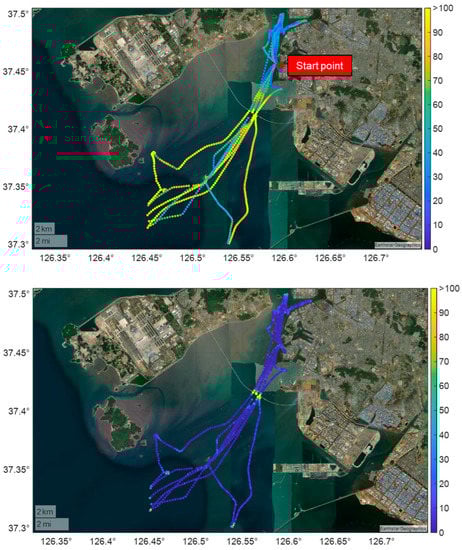
Figure 3.
eLoran positioning errors in the port area: The top image shows the eLoran positioning errors when the eLoran position was corrected using DGPS at the beginning of the experiment. The bottom image shows the eLoran positioning error when the eLoran position was corrected using the ASF map. The numbers indicated in the color bar on the right represent the error in meters.
4.3. Coastal Area
The third experiment was conducted in a coastal area outside the port, where the impact of real-time correction from a differential eLoran station was low owing to differences in the propagation paths from the eLoran transmitter. Therefore, users may experience a degradation in accuracy, even if the eLoran service provider distributes an ASF map, because of temporal factors, such as season or weather. In such cases, a system that provides precise position information, such as DGPS, can effectively correct the current eLoran position.
As shown in Figure 4, when the eLoran position was corrected using DGPS at the beginning of navigation, the 95% accuracy was 128.36 m, and the maximum error was 610.54 m. When the eLoran position was corrected using the DGPS at 500 m intervals, a 95% accuracy of 15.26 m and a maximum error of 569.95 m were observed. Similarly, when the eLoran position was corrected using DGPS at 1 km intervals, the 95% accuracy and maximum error were 24.49 m and 563.98 m, respectively. Notably, the largest eLoran position error occurred when traversing the narrow straits between the islands. Considering that previous research indicated rapid signal phase changes when the propagation path included a complex coastline, caution is necessary when using eLoran position information in such areas.
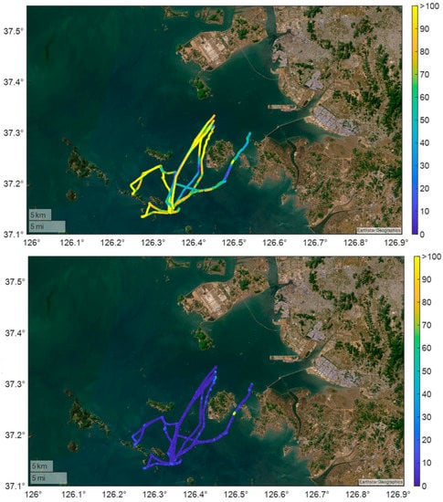
Figure 4.
eLoran positioning errors in a coastal area: the top image shows the eLoran positioning errors when the eLoran position was corrected using DGPS at the beginning of the experiment. The bottom image shows the eLoran positioning error when the eLoran position was corrected at 500 m intervals. The numbers indicated in the color bar on the right represent the error in meters.
4.4. Ocean Area
The final experiment was conducted in a far ocean area. Here, the received signal strength from the Incheon testbed transmitter, which transmits 800 W of ERP, was sufficient for navigation; however, it was insufficient to decode LDC messages. This implied that real-time ASF corrections from the differential eLoran station were unavailable. With no correction, the 95% position error in the area was 6880.49 m, and the maximum error was 20,027.36 m. This was expected because of the geometric distribution between the transmitter and user as well as the low SNR of the Incheon testbed transmitter signal.
As shown in the top image of Figure 5, when the eLoran position was calibrated using DGPS at the start of the voyage, the 95% accuracy was 425.65 m, and the maximum error was 1362.56 m. As the experiment was conducted over an extremely large area, the ASF may have varied considerably as the propagation path changed, and the position error was similar in some areas. A 95% accuracy of 135.32 m and a maximum error of 13,723.68 m were observed when the eLoran position was corrected using DGPS at 5 km intervals. Similarly, the 95% accuracy and maximum error were 171.45 m and 13,670.91 m, respectively, when the eLoran position was corrected using DGPS at 10 km intervals.
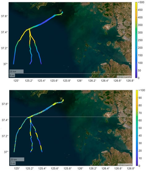
Figure 5.
eLoran positioning errors in an ocean area: the top image shows the eLoran positioning errors when the eLoran position was corrected using DGPS at the beginning of the experiment. The bottom image shows the eLoran positioning error when the eLoran position was corrected at 10 km intervals. The numbers indicated in the color bar on the right represent the error in meters.
5. Conclusions
This study examined the performance of the Korean eLoran system, a terrestrial-based navigation system, based on the four phases proposed by the IMO. Further, we proposed a DGPS-based ASF estimation method that demonstrates the possibility of calculating positions using eLoran signals in areas where eLoran LDC messages and ASF maps were readily inaccessible. A maritime experiment conducted near Incheon Port yielded promising results. The system achieved an accuracy of approximately 20 m in inland waterways, 26 m in the port approach area, and 15 m offshore, with a position error of 95% by estimating the ASF using DGPS positions at 500 m intervals and calibrating the eLoran position. Notably, even in open sea, over 80 km from the coastline, utilizing DGPS positions at 5 km intervals yielded a position accuracy of approximately 135 m without an ASF map. With improvements in the power and geometric arrangement of the Incheon eLoran testbed transmitter, the eLoran system is expected to contribute significantly to providing resilient PNT information in the West Sea.
Author Contributions
Conceptualization, P.-W.S.; methodology, P.-W.S. and S.G.P.; software, P.-W.S. and S.G.P.; validation, P.-W.S. and T.H.F. formal analysis, P.-W.S. and T.H.F.; investigation, P.-W.S., S.G.P., Y.H., K.S. and T.H.F.; writing—original draft preparation, P.-W.S. and S.G.P.; writing—review and editing, Y.H., K.S. and T.H.F.; visualization, P.-W.S.; supervision, K.S. and T.H.F.; project administration, K.S., T.H.F. and P.-W.S.; funding acquisition, T.H.F. All authors have read and agreed to the published version of the manuscript.
Funding
This study was supported by a grant from the National R&D Project, “Development of integrated R-mode navigation system”, funded by the Ministry of Oceans and Fisheries, Korea (1525012261). This study was further supported by a Korea Research Institute of Ships and Ocean Engineering grant from the Endowment Project of “Development of vertical positioning algorithm of eLoran system” funded by the Ministry of Oceans and Fisheries, Korea (1525014889).
Acknowledgments
The authors would like to thank the National Maritime PNT Office, which supported the survey in this study, and Sak Lee.
Conflicts of Interest
The authors declare no conflict of interest.
References
- Dardanelli, G.; Maltese, A. On the accuracy of cadastral marks: Statistical analyses to assess the congruence among GNSS-based positioning and official maps. Remote Sens. 2022, 14, 4086. [Google Scholar] [CrossRef]
- Lee, H.; Seo, J.; Kassas, Z.Z.M. Urban road safety prediction: A satellite navigation perspective. IEEE Intell. Transp. Syst. Mag. 2022, 14, 94–106. [Google Scholar] [CrossRef]
- Lee, Y.; Hwang, Y.; Ahn, J.Y.; Seo, J.; Park, B. Seamless Accurate Positioning in Deep Urban Area Based on Mode Switching Between DGNSS and Multipath Mitigation Positioning. IEEE Trans. Intell. Transp. Syst. 2023, 24, 5856–5870. [Google Scholar] [CrossRef]
- Specht, C. Maritime DGPS System Positioning Accuracy as a Function of the HDOP in the Context of Hydrographic Survey Performance. Remote Sens. 2023, 15, 10. [Google Scholar] [CrossRef]
- Lee, H.; Pullen, S.; Lee, J.; Park, B.; Yoon, M.; Seo, J. Optimal parameter inflation to enhance the availability of single-frequency GBAS for intelligent air transportation. IEEE Trans. Intell. Transp. Syst. 2022, 23, 17801–17808. [Google Scholar] [CrossRef]
- Park, K.; Seo, J. Single-antenna-based GPS antijamming method exploiting polarization diversity. IEEE Trans. Aerosp. Electron. Syst. 2021, 57, 919–934. [Google Scholar] [CrossRef]
- Châtre, E.; Manteiga, M. Galileo Programme Status. In Proceedings of the 35th International Technical Meeting of the Satellite Division of The Institute of Navigation (ION GNSS+ 2022), Denver, CO, USA, 19–23 September 2022; pp. 484–511. [Google Scholar] [CrossRef]
- Kogure, S. Update of QZSS. In Proceedings of the 35th International Technical Meeting of the Satellite Division of The Institute of Navigation (ION GNSS+ 2022), Denver, CO, USA, 19–23 September 2022; pp. 512–528. [Google Scholar] [CrossRef]
- DeLaPena, C., Jr. Military Communications & Positioning, Navigation, and Timing Overview: GPS Update. In Proceedings of the 35th International Technical Meeting of the Satellite Division of The Institute of Navigation (ION GNSS+ 2022), Denver, CO, USA, 19–23 September 2022; pp. 464–483. [Google Scholar] [CrossRef]
- Kim, T. KPS & KASS Status Update, 62nd Metting of the Civil GPS Service Interface Committee. 2022. Available online: https://www.gps.gov/cgsic/meetings/2022/kim.pdf (accessed on 18 May 2023).
- Grant, A.; Williams, P.; Ward, N.; Basker, S. GPS jamming and the impact on maritime navigation. J. Navig. 2009, 62, 173–187. [Google Scholar] [CrossRef]
- Seo, J.; Chen, Y.-H.; De Lorenzo, D.S.; Lo, S.; Enge, P.; Akos, D.; Lee, J. A real-time capable software-defined receiver using GPU for adaptive anti-jam GPS sensors. Sensors 2011, 11, 8966–8991. [Google Scholar] [CrossRef] [PubMed]
- Matteo, L. European Agency Warns of GNSS Outages Near Ukraine. 2022. Available online: https://www.gpsworld.com/european-agency-warns-of-gnss-outages-near-ukraine/#:~:text=In%20the%20current%20context%20of,Aviation%20Safety%20Agency%20(EASA) (accessed on 18 May 2023).
- Sadlier, G.; Flytkjær, R.; Sabri, F.; Herr, D. The Economic Impact on the UK of a Disruption to GNSS; Tech. Rep. 17.3254; London Economics: London, UK, 2017; Available online: https://londoneconomics.co.uk/wp-content/uploads/2017/10/LE-IUK-Economic-impact-to-UK-of-a-disruption-to-GNSS-SHOWCASE-PUBLISH-S2C190517.pdf (accessed on 18 May 2023).
- Bronk, K.; Koncicki, P.; Lipka, A.; Niski, R.; Wereszko, B. Concept, signal design and measurement studies of the R-Mode Baltic system, navigation. Navigation 2021, 68, 465–483. [Google Scholar] [CrossRef]
- Koch, P.; Gewies, S. Worldwide Availability of Maritime Medium-Frequency Radio Infrastructure for R-Mode-Supported Navigation. J. Mar. Sci. Eng. 2020, 8, 209. [Google Scholar] [CrossRef]
- Rizzi, F.G.; Grundhöfer, L.; Gewies, S.; Ehlers, T. Performance assessment of the medium frequency R-Mode Baltic testbed at sea near Rostock. Appl. Sci. 2023, 13, 1872. [Google Scholar] [CrossRef]
- Li, Y.; Hua, Y.; Yan, B.; Guo, W. Research on the eLoran differential timing method. Sensors 2020, 20, 6518. [Google Scholar] [CrossRef] [PubMed]
- Yan, W.; Dong, M.; Li, S.; Yang, C.; Yuan, J.; Hu, Z.; Hua, Y. An eLoran signal cycle identification method based on joint time–frequency domain. Remote Sens. 2022, 14, 250. [Google Scholar] [CrossRef]
- Shaw, G. MarRINav—Maritime Resilience and Integrity in Navigation 4000126063/18/NL/MP NAVISP-EL3-001. Available online: https://marrinav.com/wp-content/uploads/2020/04/20-03-25-Final-Report-MarRINav-v1.0.pdf (accessed on 18 May 2023).
- Son, P.-W.; Park, S.G.; Han, Y.; Seo, K. eLoran: Resilient positioning, navigation, and timing infrastructure in maritime areas. IEEE Access 2020, 8, 193708–193716. [Google Scholar] [CrossRef]
- Son, P.-W.; Rhee, J.H.; Hwang, J.; Seo, J. Universal kriging for loran ASF map generation. IEEE Trans. Aerosp. Electron. Syst. 2019, 55, 1828–1842. [Google Scholar] [CrossRef]
- Kim, W.; Son, P.-W.; Park, S.G.; Park, S.H.; Seo, J. First demonstration of the Korean eLoran accuracy in a narrow waterway using improved ASF maps. IEEE Trans. Aerosp. Electron. Syst. 2022, 58, 1492–1496. [Google Scholar] [CrossRef]
- Enhanced Loran (eLoran). Definition Document, Version 0.1, ILA. 2007. Available online: https://rntfnd.org/wp-content/uploads/eLoran-Definition-Document-0-1-Released.pdf (accessed on 18 May 2023).
- Yang, C.; Wang, Y.; Li, S.; Yan, W. Experimental Study of a Signal Modulation Method to Improve eLORAN Data Channel Communications. Sensors 2020, 20, 6504. [Google Scholar] [CrossRef]
- Offermans, G.; Johannessen, E.; Bartlett, S.; Schue, C.; Grebnev, A.; Bransby, M.; Williams, P.; Hargreaves, C. eLoran Initial Operational Capability in the United Kingdom—First Results. In Proceedings of the 2015 International Technical Meeting of the Institute of Navigation, Dana Point, CA, USA, 26–28 January 2015; pp. 27–39. [Google Scholar]
- Son, P.-Y.; Sak, L.; Tae, H.F.; Seo, K. Analysis of LDC message reception performance of Korean eLoran pilot service according to modulation methods. J. Korean Navig. Port Res. 2022, 46, 525–529. [Google Scholar] [CrossRef]
- Rhee, J.H.; Kim, S.; Son, P.-W.; Seo, J. Enhanced accuracy simulator for a future Korean nationwide eLoran system. IEEE Access 2021, 9, 115042–115052. [Google Scholar] [CrossRef]
- Lo, S.C.; Wenzel, R.; Morris, P.; Enge, P.K. Developing and validating the Loran temporal ASF bound model for aviation. Navigation 2012, 56, 9–21. [Google Scholar] [CrossRef]
- Pu, Y.; Zheng, X.; Wang, D.; Xi, X. Accuracy improvement model for predicting propagation delay of Loran-C signal over a long distance. IEEE Antennas Wirel. Propag. Lett. 2021, 20, 582–586. [Google Scholar] [CrossRef]
- Hargreaves, C.; Williams, P.; Safar, J.; Bransby, M. Radio-navigation system coverage modelling software. In Proceedings of the 2015 International Association of Institutes of Navigation World Congress (IAIN), Prague, Czech Republic, 20–23 October 2015; pp. 1–7. [Google Scholar]
- Son, P.-W.; Rhee, J.H.; Seo, J. Novel multichain-based Loran positioning algorithm for resilient navigation. IEEE Trans. Aerosp. Electron. Syst. 2018, 54, 666–679. [Google Scholar] [CrossRef]
- Son, P.-W.; Fang, T.H.; Park, S.G.; Han, Y.; Seo, K. Compensation method of eLoran signal’s propagation delay and performance assessment in the field experiment. J. Position. Navig. Timing 2022, 11, 23–28. [Google Scholar] [CrossRef]
- RTCM SC-127; Minimum Performance Standards for Marine eLoran Receiving Equipment. RTCM: Washington, DC, USA, 2017.
- Safar, J. Analysis, Modelling and Mitigation of Cross-Rate Interference in Enhanced Loran. Ph.D. Thesis, Czech Technical University, Prague, Czech Republic, 2014. [Google Scholar]
Disclaimer/Publisher’s Note: The statements, opinions and data contained in all publications are solely those of the individual author(s) and contributor(s) and not of MDPI and/or the editor(s). MDPI and/or the editor(s) disclaim responsibility for any injury to people or property resulting from any ideas, methods, instructions or products referred to in the content. |
© 2023 by the authors. Licensee MDPI, Basel, Switzerland. This article is an open access article distributed under the terms and conditions of the Creative Commons Attribution (CC BY) license (https://creativecommons.org/licenses/by/4.0/).