Article

A SAR Image-Despeckling Method Based on HOSVD Using Tensor Patches

1
School of Physics and Electronics, Shandong Normal University, Jinan 250014, China
2
Institute of Information Science, Beijing Jiaotong University, Beijing 100044, China
3
School of Management Engineering, Shandong Jianzhu University, Jinan 250101, China
4
School of Geography and Environment, Shandong Normal University, Jinan 250358, China
*
Author to whom correspondence should be addressed.
Remote Sens. 2023, 15(12), 3118; https://doi.org/10.3390/rs15123118
Submission received: 28 April 2023 / Revised: 6 June 2023 / Accepted: 13 June 2023 / Published: 14 June 2023
(This article belongs to the Special Issue SAR-Based Signal Processing and Target Recognition)

Abstract

:
Coherent imaging systems, such as synthetic aperture radar (SAR), often suffer from granular speckle noise due to inherent defects, which can make interpretation challenging. Although numerous despeckling methods have been proposed in the past three decades, SAR image despeckling remains a challenging task. With the extensive use of non-local self-similarity, despeckling methods under the non-local framework have become increasingly mature. However, effectively utilizing patch similarities remains a key problem in SAR image despeckling. This paper proposes a three-dimensional (3D) SAR image despeckling method based on searching for similar patches and applying the high-order singular value decomposition (HOSVD) theory to better utilize the high-dimensional information of similar patches. Specifically, the proposed method extends two-dimensional (2D) to 3D for SAR image despeckling using tensor patches. A new, non-local similar patch-searching measure criterion is used to classify the patches, and similar patches are stacked into 3D tensors. Lastly, the iterative adaptive weighted tensor cyclic approximation is used for SAR image despeckling based on the HOSVD method. Experimental results demonstrate that the proposed method not only effectively reduces speckle noise but also preserves fine details.

1. Introduction

Synthetic aperture radar (SAR) is an earth observation system that can generate high-resolution remote sensing images, allowing for daylong and all-weather observations. Hence, the SAR system offers unique benefits in various fields, including disaster monitoring, resource exploration, and military applications [1]. However, SAR images are often degraded by speckle noise, which is a natural consequence of coherent scattering phenomena. Unfortunately, speckle noise cannot be eliminated from SAR images and can significantly hinder interpretation, such as target recognition and image segmentation [2]. In contrast to additive white Gaussian noise (AWGN) typically found in optical images, the speckle noise in SAR images is usually multiplicative.
Speckle noise significantly impacts the understanding and interpretation of SAR images. Therefore, despeckling SAR images can considerably improve the subsequent application performance [3,4,5,6]. Owing to the limitations of early SAR image technology, traditional spatial domain despeckling approaches primarily relied on spatial filtering algorithms, such as the Lee filter [7], the Frost filter [8], and the Kuan filter [9], to remove the speckles. These methods tend to over-smooth the image while removing speckle noise, resulting in the loss of textural details. Subsequently, transform domain methods have been proposed for despeckling SAR images. Currently, the most commonly used transform domain despeckling methods include wavelet transform [10,11], contourlet transform [12], and shearlet transform [13]. Despite being more effective than spatial domain despeckling methods, transform domain filtering demands substantial computational resources, can cause image blurring, and introduce artifacts, which adversely affect subsequent image processing. Regularization-based despeckling is another popular approach to SAR images [14,15], which transforms the despeckling problem into a minimization energy function. Regularization models based on the total variance model can effectively suppress speckle noise and maintain texture. In fact, they may create an unpleasant staircase effect. In recent years, sparse representation has emerged as a captivating field of research [16]. Sparse representation aims to represent the original image with as few atoms as possible in an overcomplete dictionary, leveraging natural prior knowledge as a clean image can be represented sparsely while noise cannot. Furthermore, some methods increase adaptability by iteratively and alternately updating the atoms and sparse solutions in the dictionary using a learning strategy [17]. Unfortunately, these methods have limitations in terms of noise separation and computational efficiency. Deep learning has shown significant potential in various research areas and has also made outstanding achievements in the despeckling of SAR images. For instance, the SAR-convolution neural network (CNN) combines homomorphic transformation SAR images with deep CNN [18,19,20]. The development of deep learning has significantly improved the performance and speed of SAR image despeckling by leveraging the powerful feature extraction and adaptive parameter adjustment capabilities of deep learning [21,22]. To achieve optimal despeckling performance, deep learning models heavily rely on training with a large volume of clean real SAR images. Nevertheless, acquiring such datasets can be challenging. As a result, models trained solely on simulated SAR images are often limited to specific scenes or scenarios.
The non-local means (NLM) denoising algorithm uses similar features, including non-adjacent pixels [23]. The fundamental concept is the self-similarity of natural images, which involves estimating clean pixels by searching for similar patches in the entire image or a large window. Therefore, the NLM has achieved promising denoising results and has been widely used in the field of SAR image despeckling. The probabilistic patch-based (PPB) filter [24] replaces the Euclidean distance with a statistical similarity criterion and utilizes an iterative method to update weights. Several algorithms have combined NLM with multiscale geometric transformations and achieved good despeckling results. For instance, SAR-block-matching 3D (SAR-BM3D) filter [25] combined 3D block matching and collaborative filtering. Subsequently, Cozzolino et al. proposed a fast adaptive nonlocal SAR (FANS) filter [26] and enhanced the despeckling efficiency of SAR-BM3D. NLM has also been employed in total variation regularization [27], low-rank approximation [28], and sparse representation [29].
The NLM algorithm is effective in suppressing speckle noise. However, it can also generate artificial texture due to the influence of the blocking criterion and patch-matching accuracy, which can impede image interpretation. Various strategies, such as multiscale [30] and the gray theory [31], have been employed to improve the selection of patches with similar properties. Liang et al. [32] introduced gradient information into the similarity measure by constructing the gradient orientation map and accelerated despeckling using the fast Fourier transform algorithm. Giampaolo et al. [33] proposed an independent model-free NLM despeckling framework that provided a generic solution for despeckling a variety of SAR products. However, most of the above-mentioned despeckling methods rearrange SAR images into vectors or matrices and rely on vector or matrix calculation methods for despeckling. Unfortunately, the vectorization operation destroys the topology between similar patches, resulting in suboptimal despeckling performance. Tensors [34] offer a natural representation for multilinear data, serving as a high-order generalization of vectors and matrices. Liu et al. [35] proposed a method for estimating missing values in tensor visual data by generalizing low-rank matrices to low-rank tensors. Tensor completion techniques have demonstrated significant potential for applications such as image inpainting, video compression, and bidirectional reflectance distribution function (BRDF) data estimation. Zhang et al. [36] introduced the tensor singular value decomposition (t-SVD) for denoising and completion of multilinear data, which can handle a broader range of multilinear data as long as they are compressible in the t-SVD-based representation. Xue et al. [37] developed a method for reducing noise in hyperspectral images (HSI) using CANDECOMP/PARAFAC (CP) decomposition modeling with tensor and rank automatic determination. This algorithm significantly improves the denoising performance of HSI in various quality assessments. This paper proposes a three-dimensional (3D) SAR image-despeckling method based on patch matching and the tensor patch higher-order singular value decomposition (HOSVD) theory to effectively capture the potential information shared among similar patches and better exploit the correlation between different dimensions of SAR images. By using the non-local framework, the classified two-dimensional (2D) similar patches are stacked to construct third-order non-local tensor patches, which can better utilize the similarity of patches. It should be noted that this is the first time higher-order tensor decomposition has been applied to the field of SAR image despeckling. The proposed method effectively achieves high-dimensional SAR image despeckling by utilizing the low-rank tensor approximation technique to exploit the potential correlation and low-rank structure of SAR image data. The effectiveness of the proposed method is evaluated and compared with the existing advanced despeckling algorithms.
The remainder of this paper is structured as follows. Section 2 presents a detailed description of the material and methodology used for despeckling. Section 3 provides an analysis of the experimental results. In Section 4, a comprehensive discussion is presented to provide deeper insights. Finally, Section 5 outlines the conclusions drawn from the method. The framework of the proposed method is illustrated in Figure 1.

2. Materials and Methods

This section presents the proposed method for SAR image despeckling. Prior to the proposed method, the multiplicative noise is converted to an additive model using a logarithmic transformation. Then, the entire image is divided into overlapping patches and similar patches within a local search window are selected for each reference patch. Firstly, the gradient of the image is calculated and used to identify similar patches. Next, these similar patches are combined into third-order tensor patches. Subsequently, the iterative low-rank tensor patch approximation is applied to recover the clean tensor patches. Finally, the ultimate results are obtained by exponential transformation and aggregation of all patch estimates.

2.1. Statistics of Log-Transformed Speckle

Considering an intensity SAR image, the intensity Y is related to the backscatter return X and speckle noise B by the following multiplicative model:
Y = B X
Assuming that the speckle noise is fully developed, Goodman’s model indicates that it follows a gamma distribution with a probability density function (PDF), expressed as follows:
p ( B ) = L L B L 1 Γ ( L ) exp ( L B ) , B 0
where Γ ( · ) denotes the gamma function. Logarithmic transformation is often used to convert multiplicative noise into additive ones. Using the logarithmic operator applied on Equation (1):
Y ˜ = ln ( Y ) = ln ( B ) + ln ( X ) = B ˜ + X ˜
The random variable B ˜ follows the Fisher–Tippett distribution, defined as follows:
p ( B ˜ ) = L L e B ˜ L Γ ( L ) exp ( L e B ˜ )
The mean and variance of B ˜ can be computed as follows:
E [ B ˜ ] = Ψ ( L ) ln ( L ) , Var [ B ˜ ] = Ψ ( 1 , L )
where Ψ ( · ) is the digamma function, and Ψ ( · , L ) is the polygamma function of order L. Formula (5) shows that the noise has a non-zero mean. Therefore, a de-biasing step is required after inverse logarithmic operations.

2.2. Searching Similar Patches of SAR Images

2.2.1. Measure for Non-Local Similarity

In the presence of noise, a similar patch-searching algorithm may select irrelevant candidates, resulting in undesired artifacts due to averaging the selected patches with irrelevant data values. Conversely, it can be difficult to find enough similar patches in regions with edges or unique structures, leading to the incorrect despeckling of pixels in such areas. To address these weaknesses in the similar patch-searching algorithm, the similarity criterion proposed in [38] is utilized in this study. The similarity criterion uses the gradient information to calculate the similarity between patch x and patch y in the SAR images, as follows:
S ( x , y ) = x y G a 2 + ρ E x ¯ E x E y G a 2
where G a represents the Gaussian norm [39] and ρ is the continuous increasing bounded function. The basic idea behind the similarity criterion is to consider the gradient information, especially in regions near singular points. The gradient vector | x ( i , j ) | of the patch x in the position ( i , j ) is calculated and expressed as E x i j = | x ( i , j ) | . The matrix with entries is denoted by E x , while E x ¯ represents the average value of the elements of matrix  E x .

2.2.2. Computation of Gradient

This paper utilizes the constrained least squares method [40] to estimate gradient information from SAR images. Specifically, given a pixel point θ R 2 in a patch, the vector of data values is denoted by f : = f θ v : v = 1 , , V T . Let Z u : u = 1 , , U , U < V be a basis for Π U , which represents the space of algebraic polynomials of degree < U , and put
Φ : = z j θ i : i = 1 , , V , j = 1 , , U , Z ( φ ) ( θ ) : = z j ( φ ) ( θ ) : j = 1 , , U T .
   The approximation of the derivative f ( φ ) can be expressed as follows:
f ( φ ) ( θ ) K ( φ ) ( θ ) T f
where K ( φ ) ( θ ) : = K v ( φ ) ( θ ) : v = 1 , , V T is the appropriate coefficient vector that can be obtained by solving the following convex optimization problem:
min K ( φ ) ( θ ) v = 1 V K v ( φ ) ( θ ) 2 δ θ θ v s . t . Ψ T · K ( φ ) ( θ ) = Z ( φ ) ( θ )
The penalty function δ is typically chosen to be a smooth function that increases rapidly. A typical example is as follows:
δ ( θ ) = exp θ 2 / 2
The matrix form K ( φ ) ( θ ) = M 1 Φ Φ T M 1 Φ 1 z ( φ ) ( θ ) can be used to represent the solution to the optimization problem (8), where matrix M is defined as follows:   
                         M : = 2 diag δ θ θ v : v = 1 , , V .

2.3. Tensor and Third-Order Tensor Decomposition

2.3.1. Definition of Tensor

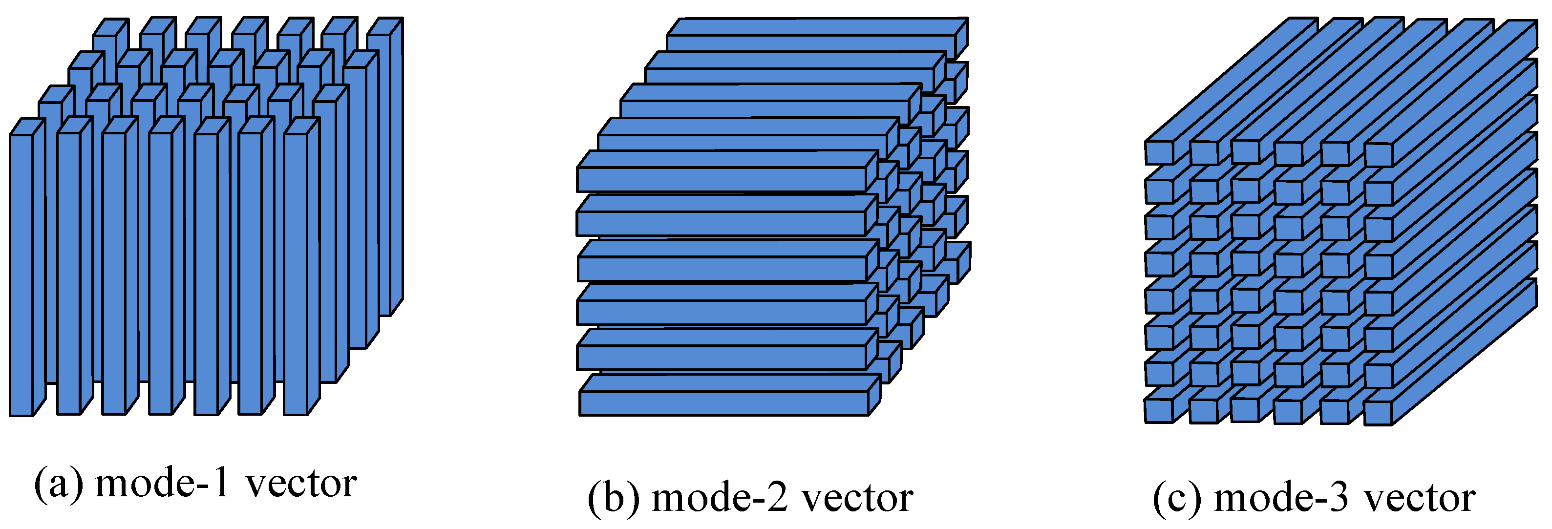
To better exploit the self-similarity of similar patches, 2D patches are converted into third-order tensors for SAR image despeckling. The tensors are equivalent to multidimensional vector arrays, which are vectors and matrices extended to multiple dimensions. Specifically, scalars, vectors, and matrices can be viewed as zero-order, first-order, and second-order tensors, respectively. To further explain the third-order tensor decomposition, a few basic definitions of tensors are provided as follows. The mode-n vector of the third-order tensor is shown in Figure 2.
Definition 1.
Given two tensors A R I 1 × I 2 × I 3 × I N and B R I 1 × I 2 × I 3 × I N of the same dimension, their inner products can be calculated as follows:
A , B = i 1 i 2 i 3 i N a i 1 i 2 i 3 i N · b i 1 i 2 i 3 i N
the Frobenius norm of tensor A R I 1 × I 2 × I 3 × I N can be obtained as follows:
A F = A , A = i 1 , i 2 , , i N a i 1 i 2 i N 2
Definition 2.
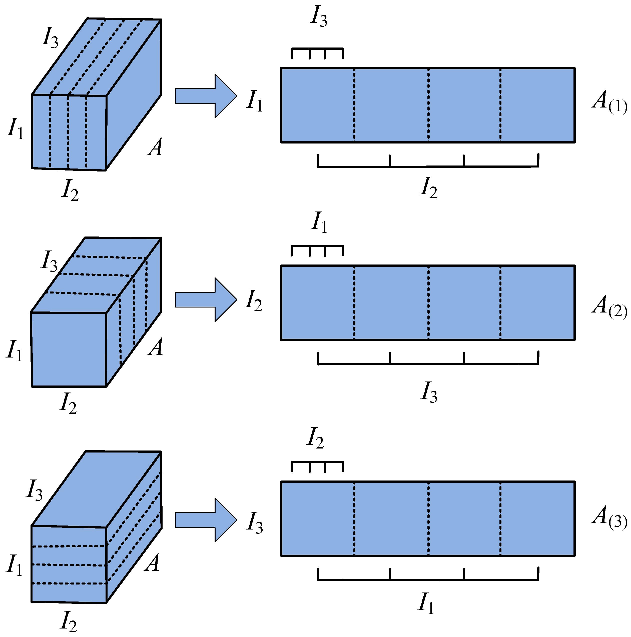
The elements of tensor A are mapped to the elements of the mode-n matrix A ( n ) R I n × I 1 × × I n 1 × I n + 1 × × I N , and a mode-n expansion of a tensor A R I 1 × I 2 × I 3 × I N of order n can be obtained. All elements of the tensor are expanded using modulo and then rearranged into a two-dimensional matrix.
Definition 3.
The mode-n rank of A R I 1 × I 2 × I 3 × I N for a given tensor A of order N is the rank of the tensor A mode-n expanded matrix A ( n ) , it can signify rank n ( A ) .
The corresponding mode-n expansion of the third-order tensor A is shown in Figure 3.

2.3.2. Higher-Order Singular Value Decomposition

The CP decomposition and Tucker decomposition are two commonly used methods for tensor decomposition. The CP decomposition expresses a given observation tensor as a combination of a sequence of rank-one quantities. The Tucker decomposition can be regarded as the extension of the matrix component analysis to higher dimensions. The HOSVD is a special form of the Tucker decomposition and can be obtained by generalizing the mode-n product of the matrix singular value decomposition (SVD) to the nth-order tensor A R I 1 × I 2 × I 3 × I N  [41].   
A = R × 1 U ( 1 ) × 2 U ( 2 ) × 3 U ( 3 ) × × N U ( N )
where U ( n ) R I n × I n , n = 1 , 2 , 3 , , N is the orthogonal basis matrix and R is the kernel tensor obtained by factorization. Unlike SVD for 2D matrices, the kernel tensor R coefficient distribution for HOSVD does not have a diagonal structure and is not necessarily non-negative. R can be expressed as follows:
R = A × 1 U ( 1 ) T × 2 U ( 2 ) T × 3 U ( 3 ) T × × N U ( N ) T
The HOSVD of the third-order tensor A R I 1 × I 2 × I 3 is expressed as follows:
A = R × 1 U ( 1 ) × 2 U ( 2 ) × 3 U ( 3 )
Figure 4 shows the schematic diagram of the HOSVD of the third-order observation tensor.
where U ( n ) R I n × I n ( n = 1 , 2 , 3 ) is the orthogonal basis matrix and R R I 1 × I 2 × I 3 is the kernel tensor obtained by factorization. Since the third-order tensor A is obtained by stacking similar patches, the traditional HOSVD denoising algorithm assumes that the core tensor is sparse. The kernel tensor R coefficient of the HOSVD decomposition is shrunk by a hard threshold as follows:
R ^ = T τ ( R )
where T τ is hard-thresholding and is defined as follows:
T τ ( R ) = R ( i , j , k ) , R ( i , j , k ) τ 0 , R ( i , j , k ) < τ
The coefficient of the kernel tensor that is less than the threshold τ is set to zero by Equation (16), and then the estimated value A ^ of the kernel tensor intercepted by the hard threshold can be obtained by the inverse HOSVD transformation.
A ^ = R ^ × 1 U ( 1 ) × 2 U ( 2 ) × 3 U ( 3 )
Therefore, the HOSVD is used for image denoising, mainly by decomposing the high-order structure of the image tensor to extract useful information. Subsequently, the tensor is reconstructed to achieve the denoising effect. For denoising, appropriate thresholds can be selected to remove the noise from the image tensor, and the remaining parts can be recombined to form a denoised image. Let us explore the application of SVD in image denoising. The self-similarity of an image refers to the presence of a high degree of similarity between similar patches. If there is no noise, the similar patch matrix should have a low-rank property when converted to column vectors. Based on this observation, image denoising has been formulated as a low-rank matrix approximation problem. Let Y R m × n be the observation matrix that comprises similar blocks of noisy observation images converted to column vectors, and X R m × n be the corresponding noiseless matrix to be estimated, which has a low-rank property. Typically, the denoising model [28] based on the 2D low rank is approximated as follows:
X ^ = arg min X 1 2 Y X F 2 s . t . rank ( X ) r
The above equation can be solved by performing SVD on the noisy observation matrix Y R m × n . In the SVD domain, Y can be decomposed into
Y = U Λ V T
the following is
Y r = U Λ r V T
including,
Λ r = diag λ 1 , λ 2 , , λ r , 0 , , 0
That is, the r singular values before the singular value decomposition of Y are retained, and Y r is the solution of Equation (18). However, the above rank constraint is an NP problem. Determining the shrinkage of rank r for singular values is the key. However, it is difficult to determine a reasonable threshold in despeckling based on SVD. Building on these observations, a new methodology for approximating low-rank tensor patches is proposed in this study. The proposed approach involves penalizing the adaptive weighted singular values of the core tensor, which is obtained via HOSVD, to achieve the low-rank tensor patch approximation.

2.4. SAR Image Despeckling Based on the Iterative Low-Rank Tensor Patch Approximation Algorithm

The basis of HOSVD is different from the fixed basis used in the SAR-BM3D wavelet transform and is obtained by decomposing the 3D observation tensor. The objective function for the low-rank tensor estimation of SAR image despeckling is expressed as follows:
                               arg min X 1 2 Y X F 2 + W 𝘍 ( X )   
where Y and X denote the noisy and latent clean images, respectively; 𝘍 represents the Frobenius norm, which can be calculated using Equation (11). W denotes adaptive weights; 𝘍 ( X ) denotes the proposed low-rank tensor patch nuclear norm, and 𝘍 ( X ) represents HOSVD, which is used to obtain the low-tensor patches from X.
In the field of SAR image processing, natural scenes are often represented by SAR images that exhibit low-rank features. Generally, 𝓁 1 norm regularization or nuclear norm regularization is frequently employed to approximate the rank function of the image. While these regularization methods can yield sparse solutions, the convexity in both approaches may introduce significant estimation bias [42]. In contrast, non-convex penalties, such as 𝓁 q ( 0 q < 1 ) , smoothly clipped absolute deviation (SCAD), or minimax concave (MC) penalties can improve the deviation problem. Non-convex penalty regularization has demonstrated many advantages over convex penalty regularization in numerous applications. In recent years, there has been significant interest in non-convex regularization methods for sparse and low-rank recovery, driven by advancements in non-convex and non-smooth optimization algorithm theories. Building upon these developments, this paper proposes an iterative adaptive weight scheme for the regularization term, the adaptive weights with 𝓁 1 -norm can be seen as types of non-convex penalties applied to the core tensor [43]. The proposed scheme involves assigning varying penalty weights to the singular values of the tensor to achieve an optimal approximation of the low-rank tensor patches. Furthermore, soft threshold operators are used to solve the non-convex objective function.
For each tensor patch A k , k = 1 K , the count of reference patches is represented by K, and the minimization problem is further expressed as follows:
min X w k A k = i w j k λ j k
the adaptive weight is denoted by w j k , where λ j k is the elemental value in the core tensor R . Due to the varying weights w j k , the adaptive weights with the 𝓁 1 -norm penalized optimization problem are non-convex. However, if the weights w j k are assigned in a non-increasing manner to the increasing absolute values λ j k of the core tensor R k , the penalized optimization problem becomes a convex problem [35].
With the above analysis, the third-order tensor A is directly despeckled. The objective function can be expressed as follows:
arg min A x t 1 2 A y t A x t F 2 + j w j t λ j t , t = 1 , , T
the kth reference tensor patch of noisy image Y is denoted by A y t , where A x t is the potential clean tensor patch corresponding to A y t , and λ j t is the value of the core tensor R . The adaptive weight is denoted by w j t , which is assigned to λ j t . After obtaining the despeckling estimate A x t , the despeckled tensor patches are put back into their original positions to form a clean image, which requires an aggregation procedure. Up to this point, the despeckling of the nth image is completed and the despeckled SAR image X ^ n is obtained.

2.5. Soft-Thresholding Proximal Operator

Compared to traditional convex penalty functions, the non-convex penalty functions may be more difficult to solve. Therefore, this paper uses the proximity operator to solve the non-convex penalty function. By solving the proximity problem for the objective function at each iteration, the proximity operator can provide an approximation to the optimal solution of the objective function. This approach effectively overcomes the difficulty of solving non-convex penalty functions and facilitates efficient optimization in high-dimensional spaces. Given a proper and lower semi-continuous penalty function P λ ( · ) and a threshold parameter λ > 0 , the scalar proximal projection can be defined as follows:
proxp λ ( h ) = arg min x P λ ( x ) + 1 2 ( x h ) 2
the proxp λ ( h ) represents the proximity operator of a vector h = h 1 , , h n R n , which can be expressed as follows:
proxp λ ( h ) = proxp λ h 1 , , proxp λ h n T
For commonly used proximity operators, the following soft-thresholding proximal operator is used in this paper:
proxp λ ( h ) = sign ( h ) max { | h | λ , 0 }
Given a patch tensor A, P λ ˜ ( · ) denotes a generalized penalty on the elemental values λ i of the core tensor R , which can be expressed as follows:
P λ ˜ ( A ) = i P λ λ i

2.6. Residual Iteration and Adaptive Weight Setting to w j t

To further enhance the efficacy of SAR image despeckling, the residual image is utilized and iteratively processed. The residual image is effective in capturing the differences between noise and signal. The iterative process facilitates continuous optimization of despeckling outcomes, resulting in improved despeckling effects and image quality. The key element of the iterative algorithm is to add the residual Y X ^ n from the nth iteration to refine the ( n + 1 ) th step despeckled image Y n + 1 .
Y n + 1 = X ^ n t + μ Y X ^ n t
where n stands for the number of iterations; and the relaxation parameter is denoted by μ . To incorporate the residual information into the despeckled image, the remaining noise variance should be estimated, which is expressed as follows:
σ n = η σ 2 1 q × r Y Y n 1 F 2
where η represents the scaling factor, which is used to control the re-estimation of noise variance. The noise variance of Y is indicated by σ , and the number of pixels in Y is denoted by q × r .
The iterative adaptive weights w j t related to each λ j are assigned as follows:
w j t = 2 2 N σ n 2 λ j + ϱ
where N denotes the number of patches per tensor A y t ; the small positive parameter is represented by ϱ > 0 , which is chosen to prevent division by zero, and σ n can be computed using Equation (29). The optimization problem (22) of the proximal soft-threshold operator (26) is solved using an iterative adaptive weight w j t . The adaptive thresholding retains the large values while filtering out the small values, thereby preserving important structural information in the image. Consequently, solution τ j t to the jth element of A x t can be expressed as follows:
τ j k = sign λ j max λ j w j t , 0

2.7. Aggregation of Despeckled Tensor Patches

When the patches are reassembled into the image, a weight is assigned to each tensor patch based on its level of noise. Specifically, the weight is defined as follows:
ϖ = r 2 × N r 2 × N + C , if C 1 0 , otherwise
where r denotes the patch size; C represents the number of thresholded elements in the core tensor and N is the count of patches in the current tensor. The resulting image can be obtained as follows:
X ^ ( x , y ) = i N x , y j j ( j ) x , y ϖ i , j Ω i , j i N x , y j j ( j ) x , y ϖ i , j
where N x , y represents all tensor patches overlapping in position (x, y); J ( i ) x , y represents all tensors in the ith tensor that overlap at position (x, y); and Ω i , j represents a pixel located at position (x, y). The flow of the tensor despeckling algorithm is shown in Algorithm 1.
Algorithm 1 Iterative low-rank tensor patch approximation algorithm for SAR image despeckling
Input: SAR image Y, the ENL L, the number of reference patches K, and iteration F
Output: despeckled SAR image X
   1: Initialization:
      Initialize X 0 = Y , Y 0 = Y , SAR image patch tensor A
   2: Iteration:
   ➀ Outer loop: for n = 1:F do
      (I) Re-estimate Y n by (28)
      (II) Re-estimate noise variance σ n by (28)
   ➁ Inner loop: for t = 1:T do
      (I) Compute U ( 1 ) , U ( 2 ) , U ( 3 ) and core tensor R y ( t ) of A y ( t ) by HOSVD via Equation (14)
      (II) For each λ j in core R y ( t ) calculate the w j t via Equation (22)
      (III) Apply threshold w j t to λ j in R y ( t ) via Equation (27)
      (IV) Estimate despeckling patches tensor by (23)
            End for
   ➂ Obtain the nth step despeckled SAR image X ^ n via Equation (33)
            End for
   ➃ Obtain the despeckled SAR image X

3. Results

This section presents the despeckling experiments conducted on simulated multiplicative noise images and real SAR images. The experimental results verify the effectiveness of the proposed method. The proposed method is compared with the current state-of-the-art filters, including PPB [24], SAR-BM3D [25], FANS [26], and Mulog [44]. The executable codes for these methods can be downloaded from the authors’ websites, accessed on 29 May 2023. (https://www.charles-deledalle.fr/pages/ppb.php; http://www.grip.unina.it/download/prog/SAR-BM3D/; http://www.grip.unina.it/download/prog/FANS/; https://www.charles-deledalle.fr/pages/mulog.php) To better measure the despeckling performance of the proposed method, three objective evaluation metrics, i.e., peak signal-to-noise ratio (PSNR), feature similarity index (FSIM) [45], and structural similarity index (SSIM) [46], are used for the simulated multiplicative noise images. A higher PSNR indicates better image quality, while a higher FSIM suggests improved preservation of image structure information, which is represented as a number between 0 and 1. For real SAR images, the equivalent number of looks (ENL) and the mean of ratio image (MoR) are used to measure the superiority of the proposed method. Moreover, the ratio image is calculated to objectively evaluate the real SAR image-despeckling performance. To facilitate a well-informed selection of parameters within the proposed algorithm, this paper conducted an analysis of their influence using PSNR and SSIM metrics, as presented in Table 1. The PSNR and SSIM values were computed by averaging across multiple images. In the proposed algorithm, the patch size was set to 7 × 7 and the search window size was set to 30 × 30. Additionally, the parameter patch number and patch stack number were set to 300 and 60, respectively.

3.1. Experiments on Simulated Multiplicative Noise Images

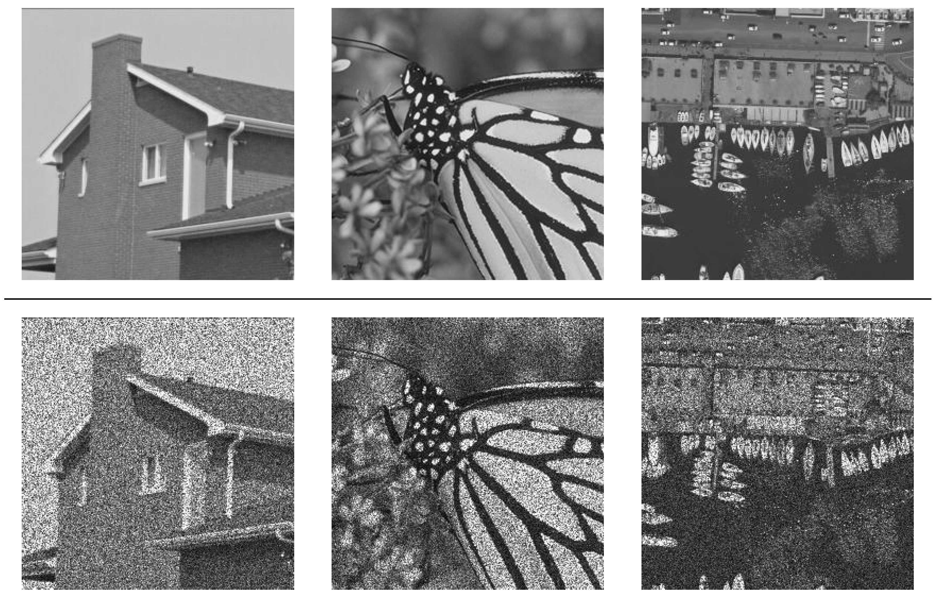
In this study, initial evaluations were conducted on three simulated multiplicative noise images, i.e., house, monarch, and Napoli. These three images are commonly used as test images in SAR image despeckling. To simulate realistic conditions, multiplicative speckle noise with different appearance levels (L = 1, 2, 4, 8) was added to each noise-free image. Reference images and corresponding noisy images (with L = 2) are presented in Figure 5.
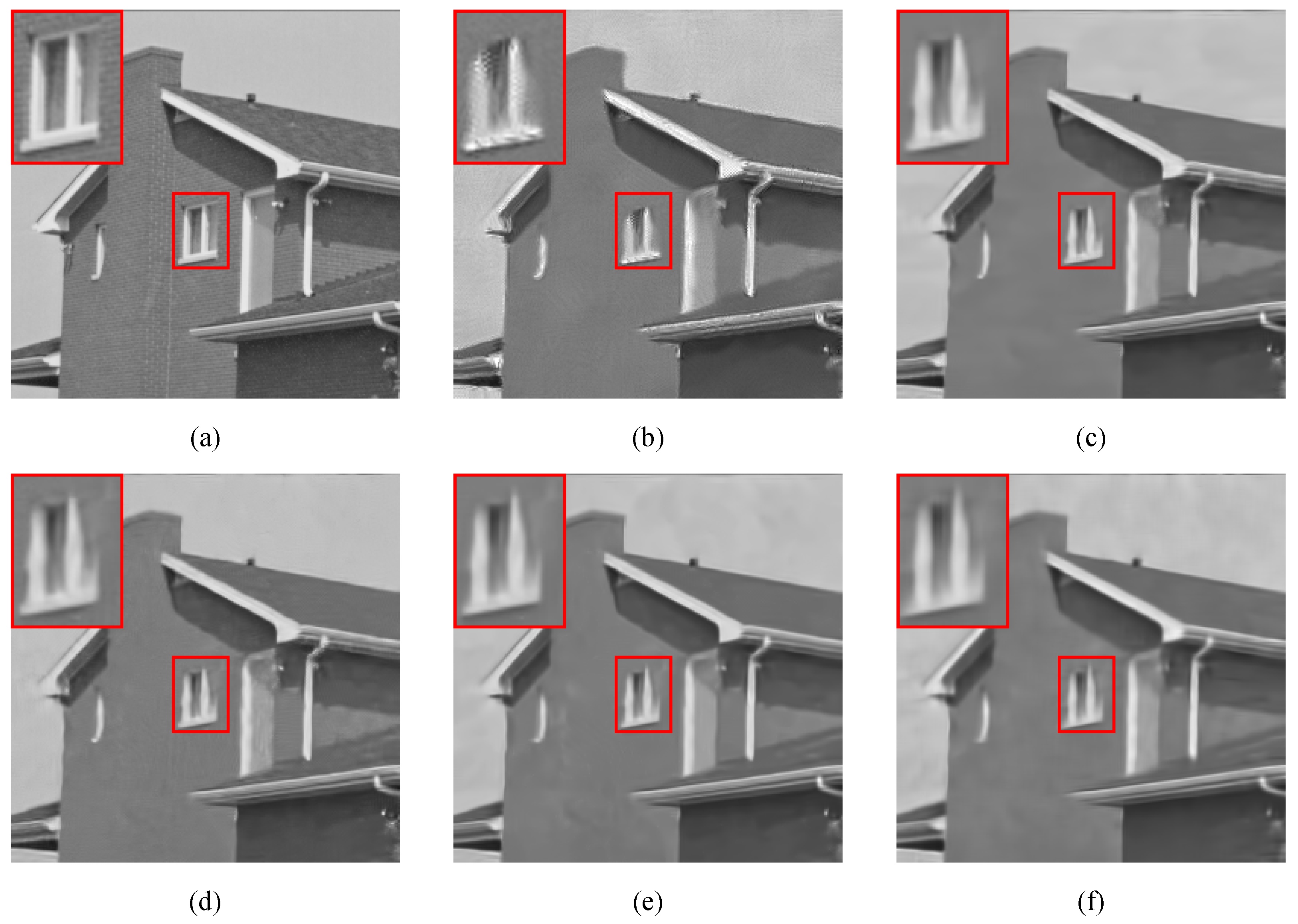
Figure 6 shows the despeckling results of each filter on the house image, along with the relevant quantitative indexes reported in Table 2. Visually, compared to the clear images, the PPB filter smooths the image excessively, resulting in the loss of detail and structural information, such as the window details highlighted by the red box. FANS effectively suppresses the noise while preserving the structural information of the image, but it has poor performance in retaining details. Although both SAR-BM3D and Mulog can preserve the details and structural information of the image well and have good despeckling performance in homogeneous regions, some unwanted artifacts are introduced during the despeckling process. Overall, the proposed method effectively despeckles the SAR images while preserving more details and structural information. Regarding the quantitative evaluation, Table 2 shows that Mulog performs well in terms of SSIM and PSNR, while FANS performs well in terms of ENL. The proposed method achieves the highest PSNR when L = 1, and consistently achieves higher FSIM and PSNR than the PPB and SAR-BM3D filters for L > 2.
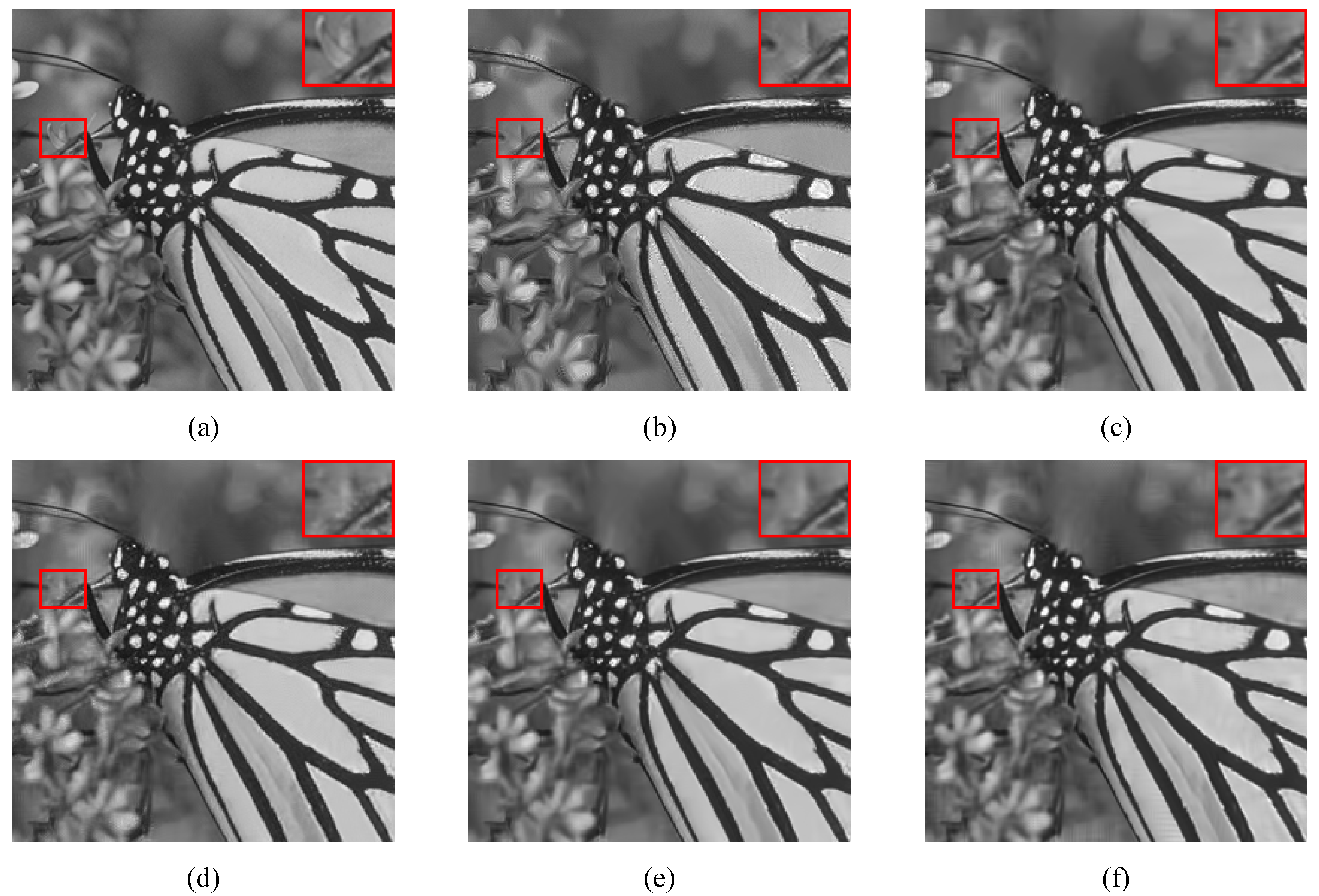
Figure 7 shows the results of the Monarch image, while the relevant quantitative indexes are reported in Table 2. It can be observed that, although the PPB filter can suppress speckle well, it removes a significant amount of textural details. FANS preserves more details than PPB, but the solution appears slightly over-smoothed. The SAR-BM3D can preserve details and textures well, but it has poor despeckling performance in homogeneous regions, which is opposite to Mulog. Overall, the proposed method can effectively balance despeckling and detail preservation, albeit with some minor artifacts. Regarding the quantitative evaluation, Mulog shows the best results in terms of SSIM and FSIM, while the highest values of PSNR are achieved by FANS. The proposed method consistently outperforms PPB, and when L= 8, it achieves the best performance in both FSIM and PSNR.
Figure 8 shows the results of the Napoli image, with the corresponding quantitative indexes reported in Table 2. It can be seen from Figure 8 that PPB over-smooth the image, resulting in a significant loss of details and texture. FANS and Mulog preserve more details than the PPB, but the resulting solution is slightly over-smoothed. The SAR-BM3D can preserve details and textures well, but its despeckling performance in homogeneous regions is suboptimal. The despeckling ability of the proposed method needs to be strengthened in the homogeneous region, but the texture and details are well preserved, which is better conducive to image interpretation. In terms of quantitative assessment, SAR-BM3D shows the best results in terms of SSIM and PSNR, while the proposed method achieves the highest values of SSIM. It can be observed from Table 2 that the proposed method consistently outperforms the PPB. All of the above objective results show that our proposed method can suppress speckle noise in homogeneous regions and preserve image details well in edge regions.

3.2. Experiments on Real SAR Images

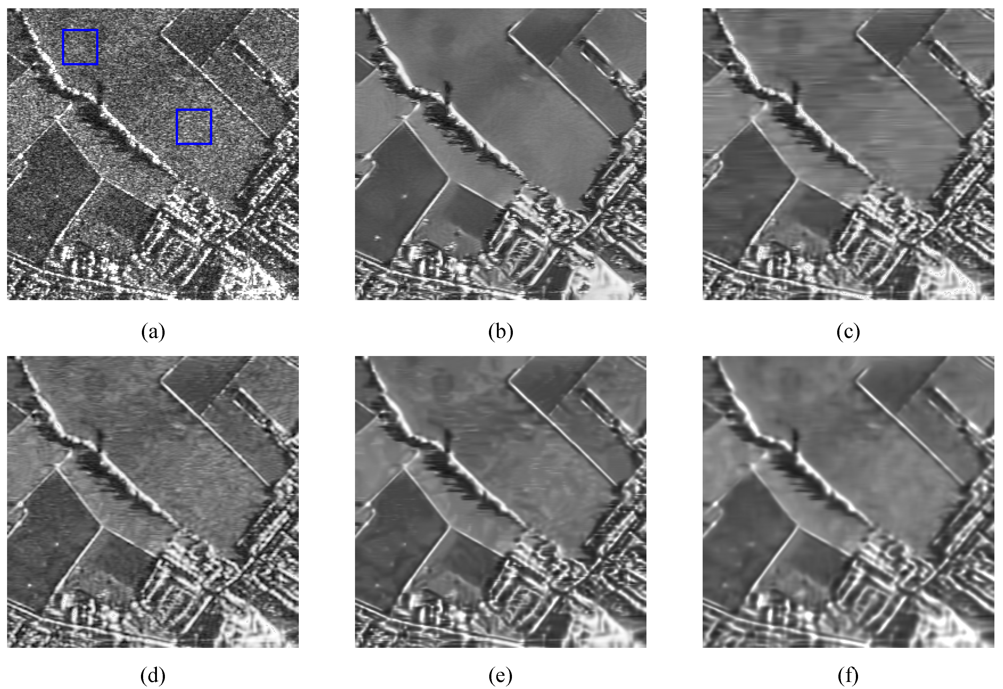
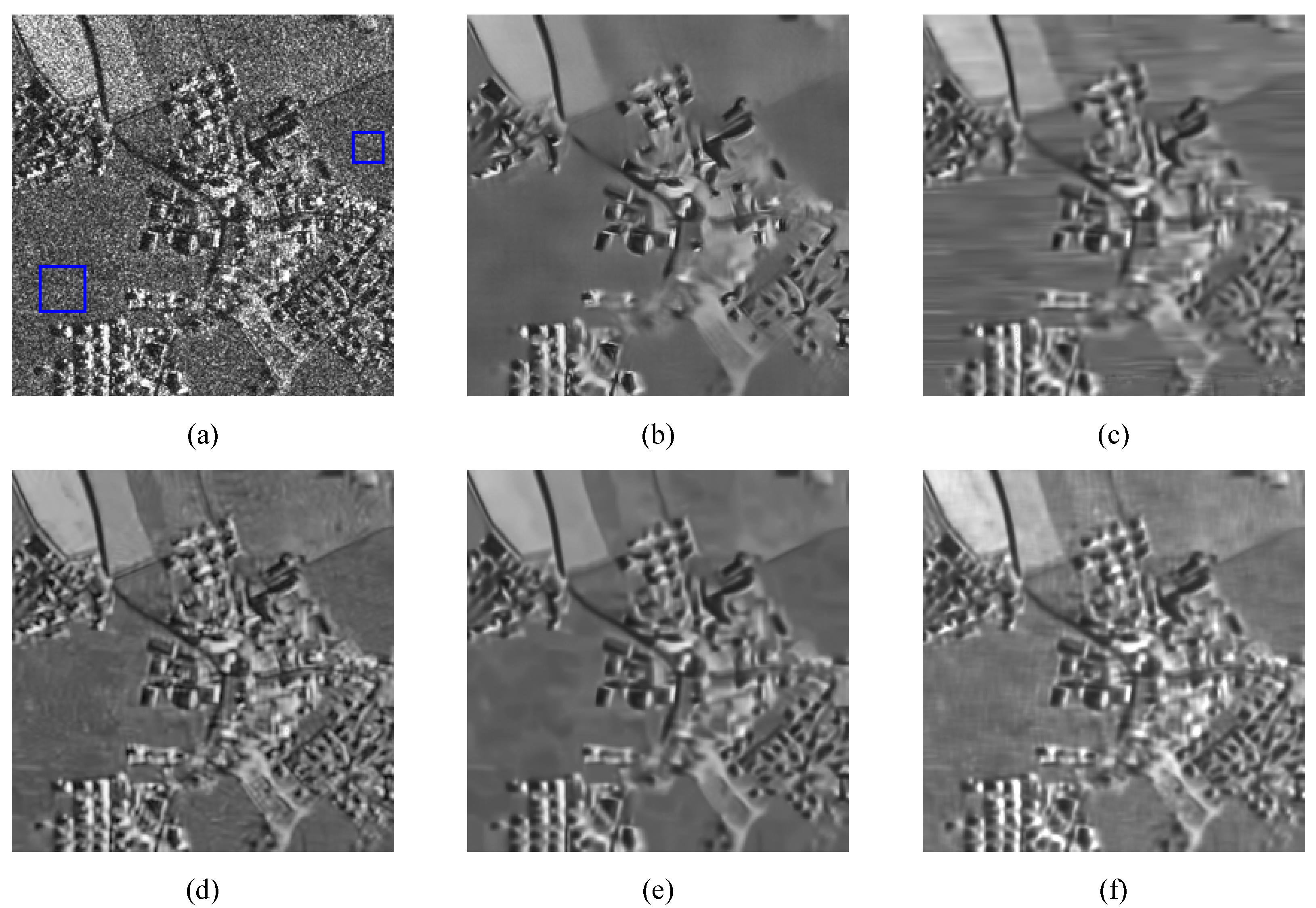
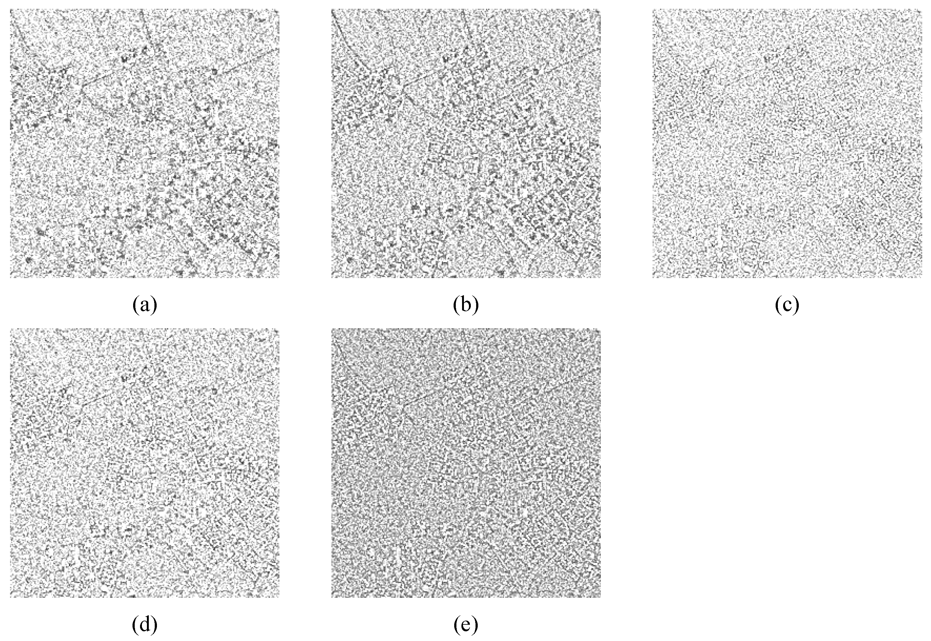
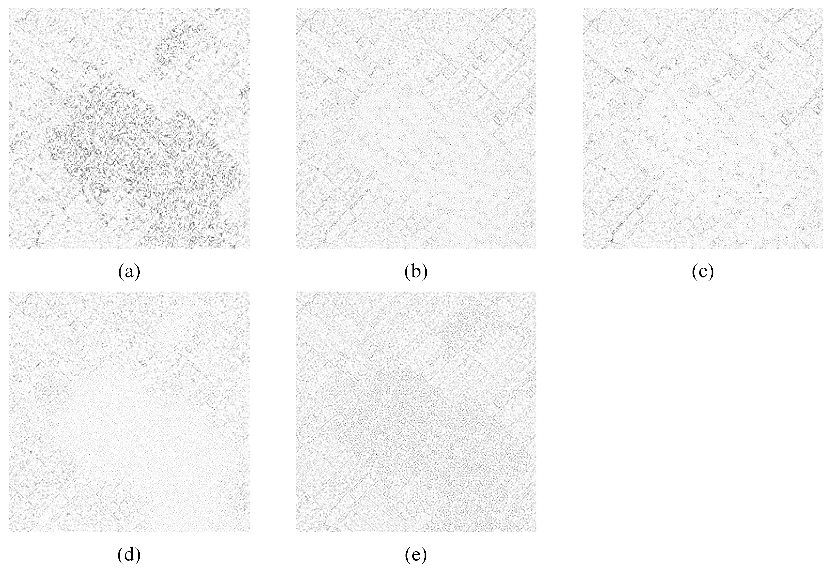
To assess the despeckling performance of the proposed method on real SAR images, three remote-sensing images from different sensors were selected. Figure 9a is a 2-look SAR image, denoted as R1, acquired by the British DRA SAR. Figure 10a is a 1-look SAR image, denoted as R2, acquired by the German TerraSAR-X satellite. The 8-look SAR image, denoted as R3, as shown in Figure 11a, was acquired by Sentinel-1. In the experiment, the ENL values were measured in the blue rectangular areas. The specific results are shown in Table 3. A larger ENL generally indicates better despeckling ability. Furthermore, ratio images were computed to compare the residual speckle noise. As per the findings of [47], an ideal filter’s ratio image (the ratio between noisy and despeckled images) should solely preserve the speckle. Hence, based on the multiplicative noise model, the MoR of the three images should be 1. To facilitate a comprehensive assessment of the proposed despeckling method’s efficiency in real-world scenarios, a comparative analysis of computational times was performed for different filters. The results are presented in Table 3, which highlights the differences in processing times among the different filters.
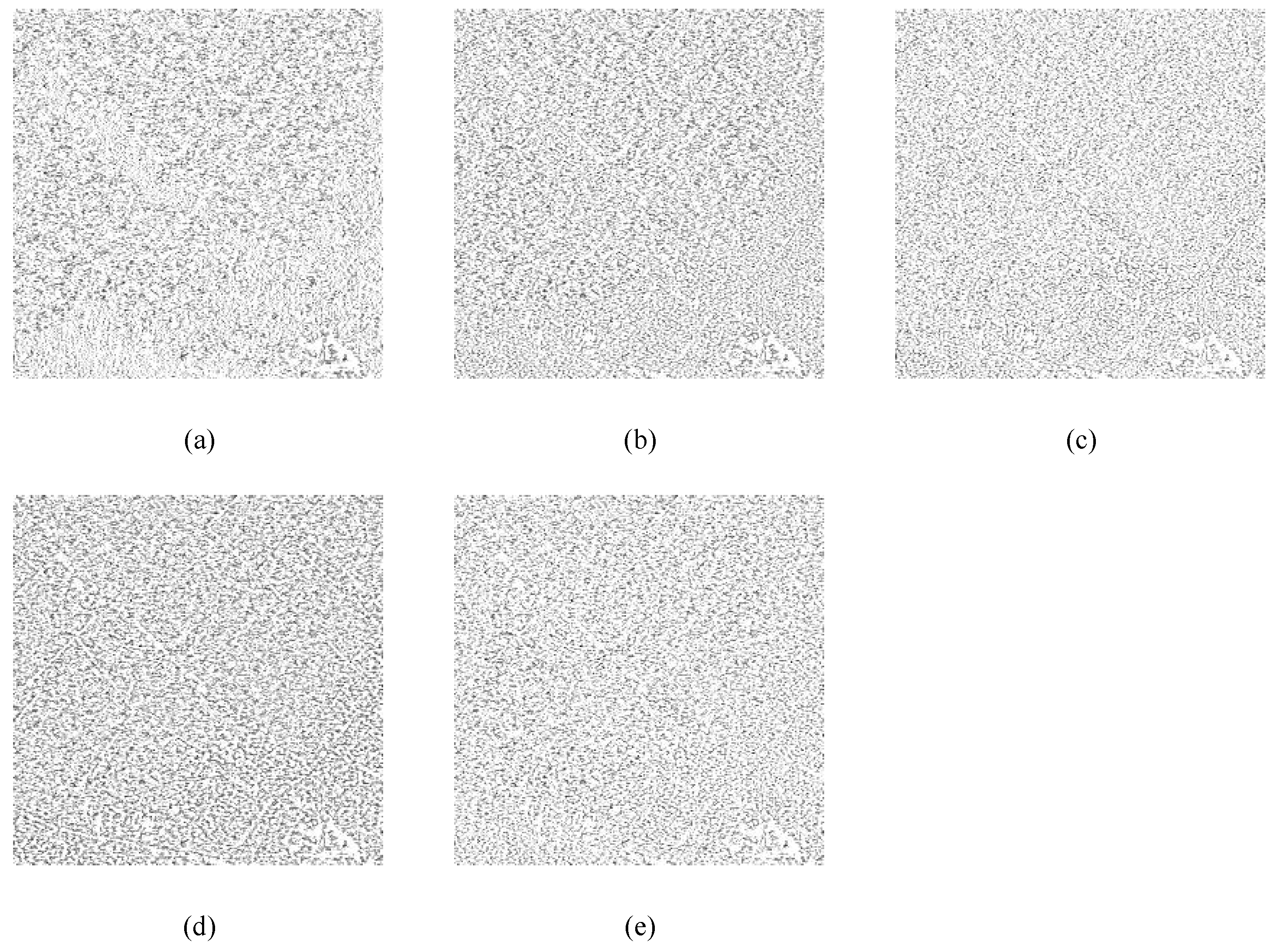
Figure 9, Figure 10 and Figure 11 display the despeckling results of real-world SAR images. Compared to the other filters, PPB leads to excessive smoothing, resulting in the loss of a considerable amount of detail and texture information, as shown in Figure 9b and Figure 10b. The SAR-BM3D can preserve details and structural information well but it has poor noise removal performance in homogeneous areas, as shown in Figure 10d. Both FANS and Mulog can reduce noise while preserving details and structural information well; however, they may introduce some unnecessary artifacts, as shown in Figure 9c,e and Figure 10c,e. Since the proposed method is an edge-preserving filter, it focuses on preserving edges and does not over-smooth details. Therefore, it does not over-smooth the homogeneous regions, such as the PPB filter, resulting in lower ENL values. Table 3 also shows that the proposed method can better use the similarity of the image to denoise and retain the detailed information. Figure 12, Figure 13 and Figure 14 show the ratio image results. The despeckled SAR images show that both PPB and FANS tend to remove excessive details during despeckling, especially in SAR images with more structural information, as shown in Figure 13a,b. This excessive despeckling of structural and edge information adversely affects the subsequent SAR image processing. On the other hand, the SAR-BM3D effectively despeckles homogeneous regions while preserving edge regions and structural information, as seen in the ratio image results in Figure 12c and Figure 13c. However, the despeckled SAR images appear distorted, resulting in the blurring of many details. While Mulog preserves details and edges information well, it introduces unnecessary artifacts in homogeneous regions, as shown in Figure 12d and Figure 13d. In contrast, the proposed method achieves perfect homogeneous despeckling while maintaining details and structural information to the greatest extent. To summarize, the experimental comparative analysis of SAR image despeckling shows that the proposed method achieves advanced visual quality, structure preservation, and speckle reduction results. However, a comparison of the filtering time results in Table 3 reveals that the despeckling time for the PPB and SAR-BM3D methods is approximately 23–24 s, while the Mulog method takes 10–11 s, and the FANS method requires only 1–2 s. In contrast, the proposed method exhibits a longer despeckling time of around 49–50 s. This indicates that there is still considerable room for improvement in achieving real-time despeckling with the proposed method. The primary contributing factor is the computationally demanding task of gradient-based similar patch classification, which necessitates significant computational resources. Additionally, the 3D tensor-based despeckling process involves the stacking of numerous 2D similar patches and relies on HOSVD, both of which further contribute to the overall computation time. Nevertheless, in practical applications of SAR despeckling, if real-time processing is not a strict requirement, the preservation of texture and detailed information is of utmost importance, and the proposed method remains a good choice.

4. Discussion

In this paper, a 3D despeckling method is proposed that stacks similar patches into tensor patches and uses the HOSVD method for low-rank tensor approximation despeckling. The proposed approach extends the application of image self-similarity to 3D and better utilizes the spatial geometric structure information of similar patches. The effectiveness of the proposed method is comprehensively evaluated and compared with the state-of-the-art despeckling methods through despeckling experiments on both simulated and real SAR images.
The experimental results demonstrate that the FSIM metric consistently outperforms FANS and PPB, particularly in the case of SAR images with more complex structural information, such as the Napoli image. Despite not having the highest PSNR and SSIM scores, the proposed method consistently outperforms PPB in terms of despeckling value across all view numbers. Visually, the proposed method achieves excellent speckle reduction while preserving image details. Although the ENL value is not the highest, the MoR values demonstrate that the proposed method effectively preserves edge information. Overall, the experimental results demonstrate and validate that the proposed method achieves an optimal balance between preserving an image’s structural and texture information and achieving effective despeckling.
However, it is noted that the proposed method may result in some artifacts while despeckling homogeneous areas. To minimize these artifacts, future work will focus on improving the accuracy of patch classification. Additionally, the process of classifying similar patches based on gradients poses significant computational demands, necessitating substantial computational resources. Moreover, the 3D tensor-based despeckling procedure involves the aggregation of multiple 2D similar patches and relies on HOSVD, both of which contribute to the overall computation time. This complexity is crucial for achieving improved despeckling performance and preserving essential image details. In future research, the authors intend to utilize approximate methods or efficient algorithms to minimize the computational complexity and reduce the despeckling time as much as possible.

5. Conclusions

This paper proposes an SAR image-despeckling method that utilizes high-dimensional information from similar patches by employing a search for similar patches and applying the tensor patch HOSVD theory. Specifically, the method extends 2D to 3D for SAR image despeckling using tensor patches for the first time. The proposed effectively achieves high-dimensional SAR image despeckling using a low-rank tensor approximation technique to exploit the potential correlation and low-rank structure of SAR image data. Previous image low-rank algorithms tended to destroy the topological structures of image patches by pulling similar patches into column vectors, which is detrimental to preserving image details. As a high-order generalization of vectors and matrices, tensors can stack 2D similar patches into 3D tensor patches, enabling HOSVD to directly despeckle the 3D tensor patches and leverage the high-dimensional structural information of similar patches. Extensive experiments demonstrate and validate the superior performance of the proposed method in synthetic and real SAR image despeckling compared with the existing advanced filters in the subjective visual evaluation and objective evaluation indices. However, the computational complexity of classifying similar patches and performing high-order singular value decomposition to approximate 3D tensor patches makes the proposed method time-consuming for despeckling. In the future, the focus will be on optimizing the mathematical algorithm and extending 3D despeckling to higher dimensions. This will leverage the self-similarity information of similar patches for SAR despeckling.

Author Contributions

Conceptualization, J.F., T.M., and F.B.; methodology, J.F. and T.M.; validation, X.W., W.L., and N.Z.; investigation, J.F., T.M., and B.H.; writing—original draft preparation, T.M.; writing—review and editing, J.F. and S.H. All authors have read and agreed to the published version of the manuscript.

Funding

This work was supported by the Natural Science Foundation of China under grant nos. 62002208 and 62172030 and the Natural Science Foundation of Shandong Province under grant nos. ZR2020MA082 and ZR2020MF119.

Data Availability Statement

The images used in this paper are sourced from the technical library.

Conflicts of Interest

The authors declare no conflict of interest.

References

  1. Moreira, A.; Prats-Iraola, P.; Younis, M.; Krieger, G.; Hajnsek, I.; Papathanassiou, K.P. A tutorial on synthetic aperture radar. IEEE Geosci. Remote Sens. Mag. 2013, 1, 6–43. [Google Scholar] [CrossRef]
  2. Ren, H.; Yu, X.; Zou, L.; Zhou, Y.; Wang, X.; Bruzzone, L. Extended convolutional capsule network with application on SAR automatic target recognition. Signal Process. 2021, 183, 108021. [Google Scholar] [CrossRef]
  3. Baraha, S.; Sahoo, A.K.; Modalavalasa, S. A systematic review on recent developments in nonlocal and variational methods for SAR image despeckling. Signal Process. 2022, 196, 108521. [Google Scholar] [CrossRef]
  4. Ponmani, E.; Saravanan, P. Image denoising and despeckling methods for SAR images to improve image enhancement performance: A survey. Multimed. Tools Appl. 2021, 80, 26547–26569. [Google Scholar] [CrossRef]
  5. Wang, G.; Bo, F.; Chen, X.; Lu, W.; Hu, S.; Fang, J. A collaborative despeckling method for SAR images based on texture classification. Remote Sens. 2022, 14, 1465. [Google Scholar] [CrossRef]
  6. Bo, F.; Lu, W.; Wang, G.; Zhou, M.; Wang, Q.; Fang, J. A Blind SAR Image Despeckling Method Based on Improved Weighted Nuclear Norm Minimization. IEEE Geosci. Remote Sens. Lett. 2022, 19, 1–5. [Google Scholar] [CrossRef]
  7. Lee, J.S. Digital image enhancement and noise filtering by use of local statistics. IEEE Trans. Pattern Anal. Mach. Intell. 1980, PAMI-2, 165–168. [Google Scholar] [CrossRef]
  8. Frost, V.S.; Stiles, J.A.; Shanmugan, K.S.; Holtzman, J.C. A model for radar images and its application to adaptive digital filtering of multiplicative noise. IEEE Trans. Pattern Anal. Mach. Intell. 1982, PAMI-4, 157–166. [Google Scholar] [CrossRef]
  9. Kuan, D.T.; Sawchuk, A.A.; Strand, T.C.; Chavel, P. Adaptive noise smoothing filter for images with signal-dependent noise. IEEE Trans. Pattern Anal. Mach. Intell. 1985, PAMI-7, 165–177. [Google Scholar] [CrossRef]
  10. Ranjani, J.J.; Thiruvengadam, S. Dual-tree complex wavelet transform based SAR despeckling using interscale dependence. IEEE Trans. Geosci. Remote Sens. 2010, 48, 2723–2731. [Google Scholar] [CrossRef]
  11. Bianchi, T.; Argenti, F.; Alparone, L. Segmentation-based MAP despeckling of SAR images in the undecimated wavelet domain. IEEE Trans. Geosci. Remote Sens. 2008, 46, 2728–2742. [Google Scholar] [CrossRef]
  12. Tao, R.; Wan, H.; Wang, Y. Artifact-free despeckling of SAR images using contourlet. IEEE Geosci. Remote Sens. Lett. 2012, 9, 980–984. [Google Scholar]
  13. Hou, B.; Zhang, X.; Bu, X.; Feng, H. SAR image despeckling based on nonsubsampled shearlet transform. IEEE J. Sel. Top. Appl. Earth Obs. Remote Sens. 2012, 5, 809–823. [Google Scholar] [CrossRef]
  14. Sun, Y.; Lei, L.; Guan, D.; Li, X.; Kuang, G. SAR image speckle reduction based on nonconvex hybrid total variation model. IEEE Trans. Geosci. Remote Sens. 2020, 59, 1231–1249. [Google Scholar] [CrossRef]
  15. Maji, S.K.; Thakur, R.K.; Yahia, H.M. SAR image denoising based on multifractal feature analysis and TV regularisation. IET Image Process. 2020, 14, 4158–4167. [Google Scholar] [CrossRef]
  16. Zhang, Z.; Xu, Y.; Yang, J.; Li, X.; Zhang, D. A survey of sparse representation: Algorithms and applications. IEEE Access 2015, 3, 490–530. [Google Scholar] [CrossRef]
  17. Jiang, J.; Jiang, L.; Sang, N. Non-local sparse models for SAR image despeckling. In Proceedings of the 2012 International Conference on Computer Vision in Remote Sensing, Xiamen, China, 16–18 December 2012; pp. 230–236. [Google Scholar]
  18. Wang, P.; Zhang, H.; Patel, V.M. SAR image despeckling using a convolutional neural network. IEEE Signal Process. Lett. 2017, 24, 1763–1767. [Google Scholar] [CrossRef]
  19. Lattari, F.; Gonzalez Leon, B.; Asaro, F.; Rucci, A.; Prati, C.; Matteucci, M. Deep learning for SAR image despeckling. Remote Sens. 2019, 11, 1532. [Google Scholar] [CrossRef]
  20. Liu, S.; Gao, L.; Lei, Y.; Wang, M.; Hu, Q.; Ma, X.; Zhang, Y.D. SAR speckle removal using hybrid frequency modulations. IEEE Trans. Geosci. Remote Sens. 2020, 59, 3956–3966. [Google Scholar] [CrossRef]
  21. Vitale, S.; Ferraioli, G.; Pascazio, V. Multi-objective CNN-based algorithm for SAR despeckling. IEEE Trans. Geosci. Remote Sens. 2020, 59, 9336–9349. [Google Scholar] [CrossRef]
  22. Liu, Z.; Lai, R.; Guan, J. Spatial and transform domain CNN for SAR image despeckling. IEEE Geosci. Remote Sens. Lett. 2020, 19, 1–5. [Google Scholar] [CrossRef]
  23. Buades, A.; Coll, B.; Morel, J.M. A non-local algorithm for image denoising. In Proceedings of the 2005 IEEE Computer Society Conference on Computer Vision and Pattern Recognition (CVPR’05), San Diego, CA, USA, 20–25 June 2005; Volume 2, pp. 60–65. [Google Scholar]
  24. Deledalle, C.A.; Denis, L.; Tupin, F. Iterative weighted maximum likelihood denoising with probabilistic patch-based weights. IEEE Trans. Image Process. 2009, 18, 2661–2672. [Google Scholar] [CrossRef] [PubMed]
  25. Parrilli, S.; Poderico, M.; Angelino, C.V.; Verdoliva, L. A nonlocal SAR image denoising algorithm based on LLMMSE wavelet shrinkage. IEEE Trans. Geosci. Remote Sens. 2011, 50, 606–616. [Google Scholar] [CrossRef]
  26. Cozzolino, D.; Parrilli, S.; Scarpa, G.; Poggi, G.; Verdoliva, L. Fast adaptive nonlocal SAR despeckling. IEEE Geosci. Remote Sens. Lett. 2013, 11, 524–528. [Google Scholar] [CrossRef]
  27. Chen, G.; Li, G.; Liu, Y.; Zhang, X.P.; Zhang, L. SAR image despeckling based on combination of fractional-order total variation and nonlocal low rank regularization. IEEE Trans. Geosci. Remote Sens. 2019, 58, 2056–2070. [Google Scholar] [CrossRef]
  28. Guo, Q.; Zhang, C.; Zhang, Y.; Liu, H. An efficient SVD-based method for image denoising. IEEE Trans. Circuits Syst. Video Technol. 2015, 26, 868–880. [Google Scholar] [CrossRef]
  29. Ozcan, C.; Sen, B.; Nar, F. Sparsity-driven despeckling for SAR images. IEEE Geosci. Remote Sens. Lett. 2015, 13, 115–119. [Google Scholar] [CrossRef]
  30. Zhou, X.; Yang, C.; Zhao, H.; Yu, W. Low-rank modeling and its applications in image analysis. ACM Comput. Surv. (CSUR) 2014, 47, 1–33. [Google Scholar] [CrossRef]
  31. Zhao, Y.Q.; Yang, J. Hyperspectral image denoising via sparse representation and low-rank constraint. IEEE Trans. Geosci. Remote Sens. 2014, 53, 296–308. [Google Scholar] [CrossRef]
  32. Liang, D.; Jiang, M.; Ding, J. Fast patchwise nonlocal SAR image despeckling using joint intensity and structure measures. IEEE J. Sel. Top. Appl. Earth Obs. Remote Sens. 2022, 15, 6283–6293. [Google Scholar] [CrossRef]
  33. Aghababaei, H.; Ferraioli, G.; Vitale, S.; Zamani, R.; Schirinzi, G.; Pascazio, V. Nonlocal model-free denoising algorithm for single-and multichannel SAR data. IEEE Trans. Geosci. Remote Sens. 2021, 60, 1–15. [Google Scholar] [CrossRef]
  34. Kolda, T.G.; Bader, B.W. Tensor decompositions and applications. SIAM Rev. 2009, 51, 455–500. [Google Scholar] [CrossRef]
  35. Liu, J.; Musialski, P.; Wonka, P.; Ye, J. Tensor completion for estimating missing values in visual data. IEEE Trans. Pattern Anal. Mach. Intell. 2012, 35, 208–220. [Google Scholar] [CrossRef] [PubMed]
  36. Zhang, Z.; Ely, G.; Aeron, S.; Hao, N.; Kilmer, M. Novel methods for multilinear data completion and de-noising based on tensor-SVD. In Proceedings of the IEEE Conference on Computer Vision and Pattern Recognition, Washington, DC, USA, 23–28 June 2014; pp. 3842–3849. [Google Scholar]
  37. Xue, J.; Zhao, Y.; Liao, W.; Chan, J.C.W. Nonlocal low-rank regularized tensor decomposition for hyperspectral image denoising. IEEE Trans. Geosci. Remote Sens. 2019, 57, 5174–5189. [Google Scholar] [CrossRef]
  38. Yang, H.; Park, Y.; Yoon, J.; Jeong, B. An improved weighted nuclear norm minimization method for image denoising. IEEE Access 2019, 7, 97919–97927. [Google Scholar] [CrossRef]
  39. Buades, A.; Coll, B.; Morel, J.M. A review of image denoising algorithms, with a new one. Multiscale Model. Simul. 2005, 4, 490–530. [Google Scholar] [CrossRef]
  40. Jang, S.; Nam, H.; Lee, Y.J.; Jeong, B.; Lee, R.; Yoon, J. Data-adapted moving least squares method for 3-D image interpolation. Phys. Med. Biol. 2013, 58, 8401. [Google Scholar] [CrossRef]
  41. De Lathauwer, L.; De Moor, B.; Vandewalle, J. A multilinear singular value decomposition. SIAM J. Matrix Anal. Appl. 2000, 21, 1253–1278. [Google Scholar] [CrossRef]
  42. Gandy, S.; Recht, B.; Yamada, I. Tensor completion and low-n-rank tensor recovery via convex optimization. Inverse Probl. 2011, 27, 025010. [Google Scholar] [CrossRef]
  43. Shen, Z.; Sun, H. Iterative Adaptive Nonconvex Low-Rank Tensor Approximation to Image Restoration Based on ADMM. J. Math. Imaging Vis. 2019, 61, 627–642. [Google Scholar] [CrossRef]
  44. Deledalle, C.A.; Denis, L.; Tabti, S.; Tupin, F. MuLoG, or how to apply Gaussian denoisers to multi-channel SAR speckle reduction? IEEE Trans. Image Process. 2017, 26, 4389–4403. [Google Scholar] [CrossRef] [PubMed]
  45. Zhang, L.; Zhang, L.; Mou, X.; Zhang, D. FSIM: A feature similarity index for image quality assessment. IEEE Trans. Image Process. 2011, 20, 2378–2386. [Google Scholar] [CrossRef] [PubMed]
  46. Wang, Z.; Bovik, A.C.; Sheikh, H.R.; Simoncelli, E.P. Image quality assessment: From error visibility to structural similarity. IEEE Trans. Image Process. 2004, 13, 600–612. [Google Scholar] [CrossRef] [PubMed]
  47. Di Martino, G.; Poderico, M.; Poggi, G.; Riccio, D.; Verdoliva, L. Benchmarking framework for SAR despeckling. IEEE Trans. Geosci. Remote Sens. 2013, 52, 1596–1615. [Google Scholar] [CrossRef]
Figure 1. The framework of the proposed method.
Remotesensing 15 03118 g001
Figure 2. The mode-n vector of the third-order tensor.
Remotesensing 15 03118 g002
Figure 3. Mode-n expansion of the third-order tensor A.
Remotesensing 15 03118 g003
Figure 4. Schematic diagram of the HOSVD of the third-order tensor.
Remotesensing 15 03118 g004
Figure 5. Test of synthetic multiplicative noise images (top line, from left to right—house, monarch, and Napoli are the clean optical images. Bottom line, from left to right—house, monarch, and Napoli are the simulated SAR images, L = 2).
Remotesensing 15 03118 g005
Figure 6. The results of different filters on the house (L = 4). The red box highlights the zoomed region of interest. (a) Clean image; (b) PPB; (c) FANS; (d) SAR-BM3D; (e) Mulog; (f) proposed method.
Remotesensing 15 03118 g006
Figure 7. The results of different filters on monarch (L = 4). The red box highlights the zoomed region of interest. (a) Clean image; (b) PPB; (c) FANS; (d) SAR-BM3D; (e) Mulog; (f) proposed method.
Remotesensing 15 03118 g007
Figure 8. The results of different filters on Napoli (L = 4). The red box highlights the zoomed region of interest. (a) Clean image; (b) PPB; (c) FANS; (d) SAR-BM3D; (e) Mulog; (f) proposed method.
Remotesensing 15 03118 g008
Figure 9. The results of different filters on R1 (L = 2). The blue boxes highlight the regions of interest used to compute the equivalent number of looks (ENL). (a) Noisy image; (b) PPB; (c) FANS; (d) SAR-BM3D; (e) Mulog; (f) proposed method.
Remotesensing 15 03118 g009
Figure 10. The results of different filters on R2 (L = 1). The blue boxes highlight the regions of interest used to compute the equivalent number of looks (ENL). (a) Noisy image; (b) PPB; (c) FANS; (d) SAR-BM3D; (e) Mulog; (f) proposed method.
Remotesensing 15 03118 g010
Figure 11. The results of different filters on R3 (L = 8). The blue boxes highlight the regions of interest used to compute the equivalent number of looks (ENL). (a) Noisy image; (b) PPB; (c) FANS; (d) SAR-BM3D; (e) Mulog; (f) proposed method.
Remotesensing 15 03118 g011
Figure 12. The corresponding ratio images for R1. (a) PPB; (b) FANS; (c) SAR-BM3D; (d) Mulog; (e) proposed method.
Remotesensing 15 03118 g012
Figure 13. The corresponding ratio images for R2. (a) PPB; (b) FANS; (c) SAR-BM3D; (d) Mulog; (e) proposed method.
Remotesensing 15 03118 g013
Figure 14. The corresponding ratio images for R3. (a) PPB; (b) FANS; (c) SAR-BM3D; (d) Mulog; (e) proposed method.
Remotesensing 15 03118 g014
Table 1. PSNR and SSIM performance comparison with different patch sizes, patch numbers, patch stack numbers, and search windows. The best results are highlighted in bold.
Patch size5 × 56 × 67 × 78 × 89 × 9
PSNR23.1123.1423.2623.2423.19
SSIM0.6790.6810.6870.6800.679
Patch number100150200250300
PSNR23.2323.2723.3323.3123.38
SSIM0.6830.6870.6910.6930.695
Patch stack number3040506070
PSNR23.0723.2523.4023.4223.37
SSIM0.6830.6870.6910.6930.695
Search window10 × 1015 × 1520 × 2025 × 2530×30
PSNR23.2123.3423.4123.4323.45
SSIM0.6860.6910.6970.6960.698
Table 2. The PSNR, FSIM, and SSIM of different filters on the simulated multiplicative noise images (L = 1, 2, 4, 8). The best results are highlighted in bold.
L = 1L = 2L = 4L = 8
MethodsPSNRFSIMSSIMPSNRFSIMSSIMPSNRFSIMSSIMPSNRFSIMSSIM
HouseNoisy image12.160.4270.09614.710.5040.15217.320.5840.22520.040.6630.316
PPB25.130.7860.64227.160.8400.72429.020.8770.78630.390.8930.823
FANS25.340.8040.75728.660.8540.81131.170.8830.84232.950.9030.860
SAR-BM3D24.620.8360.77228.140.8770.81630.900.9050.84532.120.9220.863
Mulog25.010.8350.78328.360.8700.82231.150.8940.84732.970.9140.862
Proposed25.540.8130.73328.280.8570.79730.760.8880.83632.380.9040.854
MonarchNoisy image13.470.5360.25816.040.6140.34918.750.6910.44421.520.7620.546
PPB23.000.8260.71624.720.8660.79025.990.8920.83527.630.9160.873
FANS24.210.8560.80526.570.8950.86428.520.9190.90030.230.9380.924
SAR-BM3D23.610.8530.80026.130.8900.85628.130.9150.89329.840.9330.919
Mulog23.800.8660.81326.240.9010.86728.430.9240.90430.300.9420.929
Proposed23.510.8430.75026.040.8900.82528.280.9210.89030.300.9430.920
NapoliNoisy image14.640.6060.22917.270.6280.33720.080.7590.46322.970.8260.593
PPB21.740.7130.56123.230.7830.65924.940.8450.74126.400.8850.800
FANS22.260.7100.59824.240.8040.70326.240.8690.78428.120.9100.848
SAR-BM3D22.640.7600.63924.420.8250.72426.360.8800.80228.120.9160.865
Mulog22.430.7350.62824.080.8010.70426.020.8610.77827.960.9080.843
Proposed22.330.7800.60024.150.8260.69026.140.8810.77528.040.9150.842
Table 3. The ENL, MoR, and times of different filters on real SAR images. The best results are highlighted in bold.
R1R2R3
MethodsENL1ENL2MoRTimeENL1ENL2MoRTimeENL1ENL2MoRTime
Noisy image2.902.62--2.202.62--22.4712.78--
PPB55.58366.651.0023.081345.02340.700.9922.361327.921181.271.0023.11
FANS32.6574.581.021.62100.7598.031.111.74525.66770.601.011.58
SAR-BM3D19.6322.270.9924.31127.0577.990.9924.543837.38111.760.9924.09
Mulog29.7469.611.0710.25216.92144.601.3810.02878.76859.671.0111.36
Proposed38.04151.580.9650.63137.74151.580.9949.47401.67951.580.9849.33
Disclaimer/Publisher’s Note: The statements, opinions and data contained in all publications are solely those of the individual author(s) and contributor(s) and not of MDPI and/or the editor(s). MDPI and/or the editor(s) disclaim responsibility for any injury to people or property resulting from any ideas, methods, instructions or products referred to in the content.