1. Introduction
Inverse synthetic aperture radar (ISAR) imaging technology is an effective approach to achieving high-resolution imaging for non-cooperative targets and has the merits of all-weather, all-time, and long-range [
1]. Classic range Doppler (RD) algorithm is effective for smooth moving targets under the assumption of a small angle, which simplifies the imaging process by transforming two-dimensional ISAR signal processing into two one-dimensional FFT operations. However, for targets with extreme maneuverability, the RD algorithm is no longer applicable [
2]. The rotation component during coherent processing intervals (CPI) is no longer equivalent to uniform rotation, resulting in the time-varying Doppler frequencies and leading to the ISAR image blurred along the azimuth direction, which will bring a serious challenge for the subsequent target classification and identification.
Traditional imaging methods for maneuvering targets mainly include range-instantaneous Doppler (RID) methods and parameter estimation methods [
3,
4]. The RID methods replace the traditional Fourier transform with time-frequency analysis (TFA) tools. Short-time Fourier transform (STFT), Wigner–Ville distribution (WVD), and smooth pseudo WVD distribution (SPWVD) are several common time-frequency analysis tools used in ISAR imaging [
5,
6]. These methods could reduce the blur of ISAR images for maneuvering targets to some extent, but they inevitably suffer from a tradeoff between the ability to suppress cross-terms and the time-frequency resolution. Adaptive Chirplet decomposition, chirp Fourier transform (CFT), and Radon–Wigner transform (RWT) are several common parameter estimation methods [
7,
8,
9]. By estimating the parameters of the echo, these methods could produce high-resolution images of maneuvering targets without cross-terms, but they have a strict requirement for the scatterer distribution and are sensitive to noise. In order to improve the estimation accuracy, parameter estimation methods come at the cost of high computational complexity, so they cannot meet the demands for ISAR real-time imaging, especially in low signal-to-noise (SNR) scenarios.
In recent years, deep learning (DL) has achieved good applications in target detection [
10,
11,
12], image classification [
13], signal recovery, etc. Particularly designed deep neural networks are also introduced to the radar imaging field. Providing unprecedented performance gains in resolution and imaging efficiency, these networks have overcome the main limitations of traditional methods. At present, ISAR imaging methods based on DL can be mainly classified into two categories, i.e., model-driven methods and data-driven methods.
Model-driven DL methods [
14] unfold the traditional iterative optimization algorithm into a multi-layer deep network such as the CIST network [
15], ADMMN [
16], and AF-AMPNet [
17]. They are also called deep unfolding. By setting the adjustable parameters, the network could be designed and trained in accordance with the physical models.
Deep-unfolding networks show excellent reconstruction performance while maintaining high computational efficiency and have strong interpretability [
18]. However, when imaging the maneuvering targets, these methods cannot fit well. The essence of the deep unfolding methods is the deep implementation of compressed sensing (CS) and iterative optimization algorithms [
19]. The imaging performance cannot be dominant over the upper limit of traditional methods. Therefore, without the assistance of traditional methods, model-driven methods cannot avoid the blurring of ISAR images when imaging maneuvering targets.
Typical data-driven DL methods include fully convolutional neural network (FCNN) [
20], Unet [
21], GAN [
22,
23], etc. Data-driven methods directly learn the complicated nonlinear mapping from the input low-resolution ISAR images to the super-resolution output images by designing and training the deep networks [
24]. By replacing on-line calculation with off-line network training, data-driven methods can reconstruct ISAR images efficiently and have strong robustness to various noise levels. However, there are still two challenges.
Firstly, though the existing data-driven methods show excellent performance on super-resolution and denoising, they have a weak ability to restore image details and textures information. When imaging maneuvering targets, these methods are not able to use neural networks alone to recover deblurred ISAR images. For example, ref. [
25] firstly uses the keystone transform to compensate for the main phase error in the echo caused by the maneuver and then uses the u-net network to improve the resolution. The STFT-Unet in [
26] plays a role in enhancing the resolution of the time-frequency spectrum. The above data-driven methods have to first use traditional methods to remove most of the image blur before applying deep neural networks, resulting in cumbersome imaging processes, so they are unfavorable for real-time imaging.
Secondly, the imaging performance and the generalization capability of the data-driven methods rely heavily on the datasets [
24]. The performance of the network trained by simulation data may be degraded when applied to measured data due to the scattering distributions of simulated data, and measured data are quite different. The ISAR image of the measured data is usually a combination of block regions with different shapes [
27]. However, most of the existing literature use randomly distributed scattering points to construct simulation datasets [
28], which cannot simulate the complex scattering distributions of the measured block targets.
To cope with the above challenges, we first propose a pseudo-measured data generation method based on the Deeplabv3+ network [
29] and Diamond-Square algorithm [
30]. The generated random block targets could simulate the complicated scattering distribution of the measured ISAR data. Then we construct a Uformer-based GAN, dubbed UFGAN, to present a novel unblurring ISAR imaging method for maneuvering targets. The latest proposed Uformer on CVPR 2022 has been proven to show superior performance in several image restoration tasks [
31]. In this paper, we refer to LeWin Transformer blocks to design a generator with the capability of capturing texture features as well as global information. Moreover, the global GAN and PatchGAN [
32] are combined to build a novel Transformer-based discriminator, which can fuse the local details and global features to comprehensively discriminate the generated images. The loss function we use is a combination of the Charbonnier loss, perceptual loss [
33], and adversarial loss to focus on both global similarity and perceptual features.
The main contributions of this paper include:
A pseudo-measured data generation method is proposed. We construct an aircraft ISAR imaging dataset for network training following this method. It provides a stimulating solution to an awkward predicament where the imaging performance of the existing data-driven DL imaging methods is seriously restricted by the scarcity of the publicly available dataset when imaging measured data.
Uformer, as a state-of-the-art Transformer structure, is used to construct a novel UFGAN for the restoration of deblurred ISAR images of maneuvering targets. As far as we know, it is the first attempt to apply a Transformer in ISAR imaging. The constructed network far surpasses traditional imaging methods for maneuvering targets in imaging performance and imaging efficiency and compared with the present data-driven methods, and the UFGAN-based method shows better performance in restoring the details and texture features of ISAR images.
The remainder of this paper is composed as follows.
Section 2 presents the signal model of ISAR imaging for a maneuvering target.
Section 3 describes the architecture of the proposed UFGAN in detail.
Section 4 presents the data acquisition process in detail. In
Section 5, simulated and measured experiments are presented to prove the effectiveness of the proposed method.
Section 6 concludes the full paper.
2. ISAR Imaging Signal Model of a Maneuvering Target
Assuming that the translational compensation [
34] has been finished, a two-dimensional ISAR imaging geometric model for a maneuvering target is presented in
Figure 1.
With the Y axis along the radar line of sight (LOS), a cartesian coordinate XOY is established on the target, and the center of the revolving stage
is determined as the origin of the coordinate. The distance from the origin to the radar is
. Suppose the scattering point
P rotates an angle of
during CPI, the distance from
P to the radar can be calculated by:
Under the assumption of a small imaging rotation angle for maneuvering targets, high-order motion components can be ignored, so the motion of
P in the imaging plane can be approximated as a uniformly accelerated rotation with a constant jerk. Suppose the initial angular velocity is
, the angular acceleration is
, and the angular jerk is
, the rotation angle could be written as:
The range shift of
P caused by rotation can be calculated as:
Furthermore, for small angle, we have
, and Equation (3) can be rewritten as:
Suppose the radar transmits linear frequency modulation (LFM)signal as:
where
is the rectangular window function,
is the full time,
is the fast time, indicating the elapsed time from the transmission to the reception of a pulse,
is the slow time, indicating the transmission moment of each pulse.
represents the pulse width,
is the carrier frequency and
indicates the chirp rate.
For point
P, suppose the propagation speed of electromagnetic wave is
c, the time delay of the radar signal from transmission to reception can be calculated by
, the received echo signal can be written as:
where
is the scattering coefficient of the point
P.
To simplify the calculation, the center of the revolving stage is selected as the reference point. Similarly, the time delay at the reference point can be calculated by
, then the reference signal can be written as:
The range compression signal could be obtained by “dechirp” processing as follows:
After Fourier transform to Equation (8), the high-resolution range profile (HRRP) of the target can be obtained as:
The last two phase terms are the residual video phase (RVP) and the envelope skew term, respectively, and need to be compensated for. After phase compensation, the range compressed signal can be written as:
Substituting Equation (4) into Equation (10), we have:
where
.
Suppose there are
M scattering points, including
P, within the discussed range unit. The azimuth echo signal can be obtained by adding the sub-echoes of each scattering point in the range unit:
where
,
,
.
Equation (12) demonstrates that the azimuth echo signal has the form of the multicomponent amplitude modulation-quadratic frequency modulation (AM-QFM) signal [
35], which can more accurately describe the imaging characteristics of the maneuvering targets. The quadratic and cubic phase term of the AM-QFM signal leads to the blurring of ISAR image. The center frequency
, chirp rate
, and derivative of chirp rate
of the AM-QFM signal are decided by the initial angular velocity
, angular acceleration
and angular jerk
of the turntable model, respectively.
The last phase term indicates the migration through range cells (MTRC) of the ISAR image. It shows that the MTRC of the maneuvering target has nothing to do with the motion parameters.
According to Equation (12), we can further give the following relationship:
where
,
are called relative acceleration ratio and relative jerk ratio in this paper, respectively. Equation (12) can be rewritten as:
According to Equation (15), blurring only occurs along the azimuth direction of the ISAR image for the maneuvering target, and the blurring degree of the image is only related to the azimuth coordinates of the scattering point once the motion parameters are determined.
3. Proposed UFGAN-Based ISAR Imaging for Maneuvering Target
Profiting from the excellent simulation capability for arbitrary data distributions, GANs receive widespread use in the imaging field. GAN consists of two key components, i.e., generators and discriminators. The adversarial relationship between the above two gives GAN the ability to generate simulated images that are similar to real images. To obtain a high-quality deblurred ISAR image that looks real, we construct the UFGAN and propose a novel UFGAN-based ISAR Imaging method for maneuvering targets. In this section, we will present the imaging framework, the network architecture, and the loss function in detail.
3.1. Imaging Framework Based on UFGAN
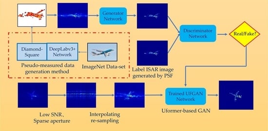
The overall imaging framework for maneuvering the target is shown in
Figure 2. By setting different motion parameters for the simulated scattering points, ISAR echoes with motion errors can be obtained. As analyzed in
Section 2, the resulting ISAR images by the RD algorithm are blurred in azimuth direction due to the phase error introduced by the target maneuver. The generator is to transform the blurred image into the deblurred image, and the discriminator is to determine and distinguish whether the generated image is real or fake. The generator and the discriminator fight each other until the discriminator can barely distinguish between real and fake images.
Some ISAR images obtained from measured data have small sizes and low resolution due to the small number of range samples or azimuth samples. Existing data-driven DL imaging methods generally directly input the small-size and low-resolution images to neural networks, and the restoration effect is limited by the small number of pixel points of the images. The network cannot learn enough features to recover the details and textures of the images and, therefore, cannot obtain high-quality ISAR images.
In this paper, we add a “resize” operation in the training stage and testing stage to increase the size of small images by performing BiCubic interpolation before they are input to the network. Moreover, delicate label images with higher resolution and finer details are also presented. Ideal ISAR images are obtained by convolving the coordinates of simulated scattered points with PSF, so it is easy to obtain delicate label images by the simulated training data. This operation has two benefits. Firstly, it helps the network to learn more hidden layer features and obtain high-quality ISAR images. Secondly, the image is resized before it is input to the network so that the network can keep the input and output images with the same resolution, thus avoiding the need to adjust the network parameters and retrain when the input and output images are of different sizes.
In the testing stage, due to the publicly available measured echo data of maneuvering targets being rare, we used the ISAR-measured echo data of smooth targets to equivalently generate the echoes of maneuvering targets by means of the Fourier interpolation method. The details of the method are given in
Section 4.
3.2. Design of the Proposed UFGAN
In our design of UFGAN, the adversarial mode of GAN is adopted to make the deblurred images generated by the network closer to the ideal high-quality ISAR images. The locally-enhanced window (LeWin) Transformer blocks and the learnable multi-scale restoration modulators are used to build a novel generator to restore more image details. Global GAN and PatchGAN are combined to construct a new Transformer-based discriminator to improve the discrimination criteria of generated images by comprehensively evaluating global information and texture features. The Charbonnier loss, perceptual loss, and adversarial loss are combined to construct a comprehensive loss function to match the design of the network.
3.2.1. Generator
The overall architecture of the proposed generator is a symmetric hierarchical structure following the spirits of U-Net, as shown in
Figure 3. The generator consists of an encoder, a bottleneck, a decoder, and several multi-scale restoration modulators. The input is the blurred ISAR image represented by
, with the image size of
and the channels of 3. Firstly, a 3 × 3 convolution with LeakyReLU is adopted to extract the shallow features represented by
. Then
is fed into four consecutive encoder levels. Each level includes several LeWin Transformer blocks connected in series and a down-sampling operation of a 4 × 4 convolution with stride two. After each level, the height and width of the feature maps are halved while the feature channels are doubled. Next, LeWin Transformer blocks connected in series as the bottleneck layer are used to capture longer dependencies.
The decoder has a symmetric structure with the encoder. Similarly, each decoder level consists of an up-sampling operation of 2 × 2 transposed convolution with stride two and a group of LeWin Transform blocks. Each level doubles the height and width of the feature maps while halving the feature channels. Owing to the design of the skip connection, the feature maps fed into the next decoder level are the concatenation of the output of the up-sampling layer and the features from the corresponding encoder level.
The multi-scale restoration modulators are denoted as learnable tensors with the shape of , where M indicates the size of the window. The modulators are attached to all non-overlapping windows separately and act as a shared bias to calibrate features, which improves the adaptability of the network and promotes recovering more detail.
At last, the feature maps output from the encoder are flattened to two-dimensional feature maps and sent to the output projection layer with a 3 × 3 convolution. Then the residual image is produced and superimposed on the input image to generate a deblurred high-resolution ISAR image .
3.2.2. Discriminator
Traditional global discriminator aims to distinguish between the generated and real images by considering images holistically without focusing on whether the patches are well-matched to the global image. In contrast, PatchGAN [
32] slides a window over the input image and obtains a scoring matrix to judge whether each patch is real or fake, which is more effective in revealing local details and capturing high-resolution.
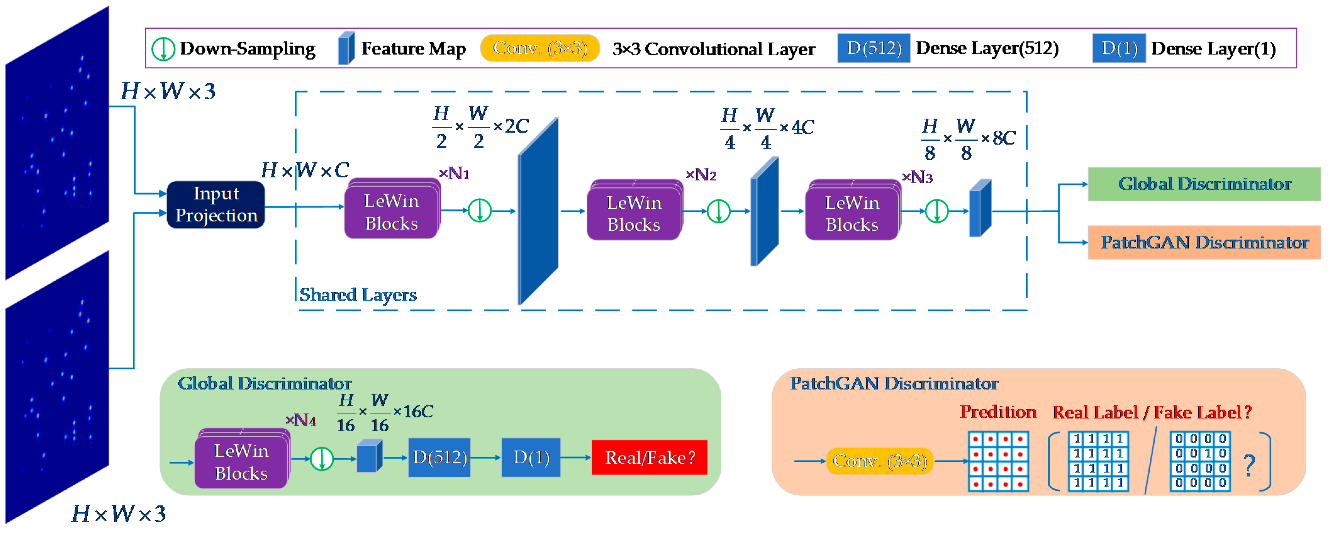
In the design of our proposed discriminator, as shown in
Figure 4, global GAN and PatchGAN are fused. Firstly, a shared layer consisting of LeWin Transform blocks and down-sampling layers is presented to extract shallow features, which have a similar structure to the encoder in the generator. After three levels, the network is divided into two paths. In one path, two dense layers are used, with channels 512 and 1 following an encoding layer to extract the global features. The other path employs a 3 × 3 convolutional layer to output a feature matrix containing all patch-level features for evaluating the local texture details.
By incorporating the two paths of global GAN and PatchGAN, the overall architecture integrates the local context and global information and provides a comprehensive evaluation of the image as a whole, as well as the consistency in local details.
The performance of the generator and discriminator is constantly improved as they work against each other, and the network eventually outputs deblurred images close to the real ISAR images.
3.2.3. LeWin Transformer Block
Standard Transformer structure has two disadvantages in image restoration. Firstly, it exploits the global self-attention on feature maps, leading to high computational costs as quadratic to the size of the feature maps. Secondly, the Transformer suffers a limited capability of leveraging local context, which is significant to restore deblurred ISAR images with high resolution.
Unlike the standard Transformer, the LeWin Transformer block performs a multi-head self-attention (W-MSA) for the non-overlapping local windows to reduce the computational cost, as shown in
Figure 5. Moreover, the traditional Feed-Forward network is improved by adding a deep convolutional layer to enhance its local expression ability as the Locally-enhanced Feed-Forward Network (LeFF).
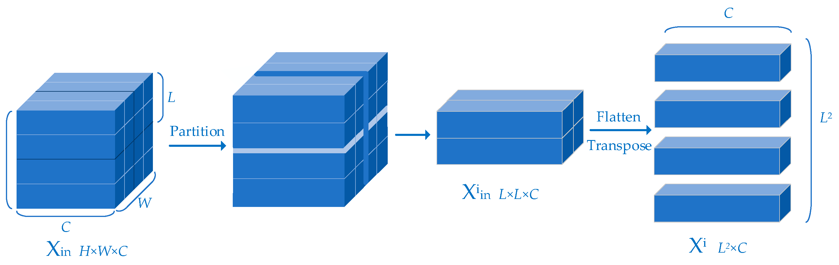
Figure 6 illustrates how the feature map is divided into non-overlapping windows.
Suppose the feature map
is partitioned into non-overlapping windows of the size of
, the feature map in the
i-th window
is flattened and transposed to be as
, where
,
. Next, by applying self-attention,
is projected to the query, key and value represented by
and
, respectively:
where
,
and
are the projection matrices. Next,
,
and
are respectively divided into
k heads:
The Self-Attention (SA) for the
j-th head can be written as:
The output feature map
of the
i-th window can be obtained by concatenating the above attention value and being reshaped:
where
presents the reshaping operation and
presents concatenating,
denotes learnable parameters, and
denotes the embedding position information. At last, the output feature maps of all image patches
are combined to obtain the overall feature map of the entire image
.
Adjacent pixels are the essential references for image restoration, but the present Feed-Forward Network (FFN) in the standard Transformer shows a limitation in extracting local context information. The design of LeFF overcomes this drawback by adding a 3 × 3 depth-wise convolutional layer to the Feed-Forward Network.
The design of the LeWin Transformer Block can obviously reduce the computational cost. Given the feature map , the computational complexity of the standard Transformer is , while the computational complexity of the LeWin Transformer module is .
3.3. Loss Function
The role of the loss function is to optimize the network in the expected direction during training. Different designs of the loss function will improve the performance of the output images in different aspects. Using a combination of several kinds of loss functions can improve the overall performance of the output images.
3.3.1. The Charbonnier Loss
Exploiting Mean Square Error (MSE) as the loss function promotes a high peak signal-to-noise ratio (PSNR) of the reconstruction results. However, the high-frequency information is easily lost, and the over-smooth texture will appear by MSE, which will make some weak scatterers disappear in ISAR images. In order to overcome this issue, the Charbonnier loss function is adopted as follows:
where
is the output deblurred ISAR image,
is the ideal unblurred ISAR image, and
[
31,
36,
37] is a constant to stabilize the value in experiments.
3.3.2. The Perceptual Loss
In order to achieve high-quality ISAR imaging while removing the blur, the perceptual loss focusing on image texture and edge features is used. Instead of calculating the loss between the output image and the ideal image directly, the key idea of perceptual loss is to compare the feature maps of the real image and the generated image, enhancing the similarity in feature space. The perceptual loss can be formulated by:
where
,
,
represent the height, width and channel of the feature map,
represents the output feature map of the
i-th layer and
is a function to obtain the feature map of an image. We select the fourth layer to calculate the perceptual loss.
3.3.3. The Adversarial Loss
The classic generative adversarial loss of GAN suffers from training difficulties, unstable gradients and mode collapse, etc. In order to train the network stably, the adversarial loss function of Wasserstein GAN with gradient penalty (WGAN-GP) proposed by Ishaan et al. is used [
38]. WGAN-GP presents the definition of the Earth-Mover (EM) distance, and the objective function can be derived as:
where
E represents taking average value,
represents the sample image imposed a penalty.
indicates the distribution of the image,
and
indicate the output of the generator and discriminator, respectively.
indicates the gradient,
is the gradient penalty coefficient and the last term is the additional gradient penalty to constrain network training. The discriminator loss and generator loss with gradient penalty can be written as:
3.3.4. The Overall Loss Function
Finally, the overall loss function can be obtained by the weighted sum of the above three loss functions:
where
,
,
are three tradeoff parameters to control the balance of the combination of loss functions. In specific, the generator parameters are updated by overall loss
, the global GAN path and the PatchGAN path are trained by
and
, respectively. The generator and discriminator are trained in steps. During each mini-batch, firstly, the discriminator is fixed when training the generator, and then the generator is fixed when training the discriminator.
4. Data Generation
4.1. Generation of Simulated Targets
In practice, the scattering points on a target do not always emerge individually but exist in the form of regions or blocks. According to the scattering distribution characteristics behaved in ISAR images, we divide the imaging targets into two categories, i.e., point targets and block targets. Point targets are composed of individual scattering points and can be easily simulated by setting up randomly distributed scattering points. However, for a block target, the spectrum of the ISAR image is mixed and superimposed due to the aggregation characteristics of the scattering points, leading to rich image details and texture information. The block targets simulated by simple shapes are quite different from the real data.
Existing data-driven DL methods directly use the network trained by simulated point targets to image the measured block targets. However, this approach only preserves the pixels with large magnitudes as the individual scattering points, ignoring the weak scatters around and losing a lot of image details. In this paper, we propose a pseudo-measured data generation method to generate a variety of block targets with similar scattering distributions of the real measured data. Due to our focus on imaging for aircraft targets, the generation of various pseudo-measured aircraft block targets is taken as an example, as shown in
Figure 7.
The processing steps of the method can be presented as follows:
The first step is to acquire varieties of aircraft geometric outlines. We use the images under “aeroplane” category in the PASCAL VOC2012 Augmented Dataset [
39] to train the DeepLabv3+ network to be able to specifically segment geometric outlines from images containing aircraft targets. Next, by inputting images under the categories of “airliner” and “warplane” in the ImageNet2012 dataset [
40] at a total of 2602 into the trained network model, 2602 images of aircraft geometric outlines are finally obtained.
The second step is gridding. Each aircraft geometric outline is meshed and mapped to a plane Cartesian coordinate with the size of 40 m × 40 m.
The third step is to generate random blocks within the gridded aircraft geometric outlines. The Diamond-Square algorithm is a random terrain generation algorithm that can randomly generate terrains with various shapes, such as mountains, hills, and oceans, in the grid of virtual scenes. Inspired by this, we refer to the Diamond-Square algorithm to randomly generate continuous scattering blocks within the aircraft’s geometric outlines.
Starting from the initial conditions, the scattering coefficient grid is continuously refined and calculated through the Diamond step and the Square step. The Diamond step is to calculate the scattering coefficient of the intersection of the square diagonals by a 2D random midpoint displacement algorithm, and the Square step is to calculate the scattering coefficients of the midpoint of each side of the square with the same random offset as the Diamond step. The detailed algorithm steps can be found in
Appendix A.
Through the iterative calculation of the two steps, the scattering coefficients of all grid points can be obtained. Some examples of the generated block targets are shown in
Figure 8.
4.2. Acquisition of Blurred ISAR Images
For simulated targets, the blurred ISAR images of maneuvering targets can be easily obtained according to Equation (15). However, for real data, most of the publicly available ISAR-measured data are collected from the detection of stationary moving targets. To address the problem that the measured ISAR data of real maneuvering targets are scarce, the Fourier interpolating re-sampling method is used to generate the equivalent ISAR echo data of maneuvering targets based on the existing measured data of smooth targets.
As indicated in
Section 2, for a maneuvering target, the uniform motion or uniform acceleration motion model is not enough to accurately describe the motion state of the target. By retaining the third derivative term of displacement with respect to time, the motion state of the target is modeled as a variable acceleration motion as:
where
,
,
represent the angular velocity, the angular acceleration and the angular jerk of the target, respectively.
Assuming that the slow time sampling interval is
and the number of azimuth sampling is
when the target rotates at a uniform angular velocity
, and the total angle the target rotates during the CPI can be calculated by:
When the target rotates the same angle
with variable acceleration as shown in Equation (26), assuming that the angular velocity increment caused by angular acceleration is
, the angular acceleration increment caused by the angular jerk
is
, the radar slow time sampling interval is
, and the number of sampling is
, we can obtain:
The above system of equations can be solved as:
When observing the variable acceleration moving target, the rotation angle at the
n-th
sample point can be calculated as
where
.
Since the radar pulse repetition interval is fixed, the uniformly moving target is sampled with an equal interval, while the variable-speed moving target is sampled with an unequal interval. Therefore, the slow-time sampling signal of the variable-acceleration moving target can be obtained by performing interpolating re-sampling on the echo of the uniform moving target according to the displacement change rule indicated by Equation (30).
Suppose the slow time sampling signal of the uniform moving target is
, by converting the distance axis of the signal into the time axis, the slow time sampling sequence
can be obtained. The discrete Fourier transform of
is:
Assuming that the slow time sampling signal of the variable acceleration moving target is
, the interpolated slow time sampling sequence of the variable acceleration moving target
can be obtained by inverse Fourier transform as:
According to Equation (32), once we know the velocity increment P and acceleration increment Q of the variable acceleration movement during the CPI period, we can perform interpolating re-sampling through the slow time sampling sequence of uniform motion with the same moving distance and obtain the equivalent slow time sampling sequence of the maneuvering target.
4.3. Acquisition of Label ISAR Images
As shown in
Figure 1, assuming the total rotation angle during CPI is
Ω, the echo signal of the target can be regarded as the sum of the backscattered field of each scattering point as:
where
represents the total number of scattering points on the target,
is the scattering coefficient, and
is the coordinate location for the
i-th scattering point.
represents the wave number. Under the condition of small angle,
can be approximated as
, where
is the center frequency and
is the wave number. Therefore, Equation (33) can be simplified as:
For ISAR imaging, the two-dimensional point spread response (PSR) of range direction and azimuth direction can be expressed by:
where
B represents the bandwidth of the transmitting signal.
represents the central value of the coherent accumulation angles.
The ideal ISAR imaging of all scattering points on a target can be obtained by 2D inverse Fourier integral (2D-IFFT) of the echo signal
as:
where
and
represent the minimum and maximum values lower of the spatial frequency.
and
represent the initial and final look-angles,
is the impulse response.
It can be seen from Equation (36) that the 2D ISAR imaging result is nothing but the convolution of the position coordinates of all scattering points on the target with the 2D PSF function.
6. Conclusions
For ISAR imaging of maneuvering targets, the existing deep learning methods could not avoid the blurring of ISAR images without the assistance of traditional methods such as RID and show a weak ability to restore image details and textures. In this article, a novel unblurring ISAR imaging method for maneuvering targets based on UFGAN is proposed. Firstly, according to the derivation of the azimuth echo signal with the form of a QFM signal, the blurred ISAR images for network training are obtained. To improve the generalization in measured data, we propose a pseudo-measured data generation method based on the DeepLabv3+ network and the Diamond-Square algorithm. Then we use the LeWin blocks and multi-scale restoration modulators to build a novel UFGAN, which can effectively restore the image details. The discriminator is designed by combining the PatchGAN and global GAN to aggregate the local and global information to provide a comprehensive evaluation of the image as a whole as well as the consistency in local details. A comprehensive loss function to consider both perceptual loss and adversarial loss is designed to match the performance of the network. In the test stage, to verify the effectiveness of the network on the measured data, Fourier interpolating re-sampling is used to obtain the equivalent ISAR echo of maneuvering targets. Finally, we conducted simulated and measured experiments and comparisons under sparse aperture and low SNR conditions to verify the effectiveness and efficiency of the proposed method.
Noticing that the proposed method cannot succeed in effectively imaging multiple maneuvering targets because the motion parameters of each target are different. In order to cope with the issue, a recognition module might be needed to distinguish different objects in one imaging scene according to the degree of blurring, and then different partitions of the image can be processed separately.


