1. Introduction
The accurate and efficient progress monitoring of under-construction buildings is a prerequisite for effective project management [
1,
2,
3,
4,
5]. Current methods of progress monitoring are based on manual measurements and extensive processing performed by construction staff. The manual process with a dominant human presence consumes a lot of time and labor and can lead to inaccurate or missing information; therefore, accurate automated alternatives should be pushed forward [
6,
7,
8].
Recently, several studies have been performed on automated progress monitoring through a model-based assessment where the as-built model of the building is compared with its as-planned model [
1]. A three-dimensional (3D) point cloud of the building, acquired through reconstruction technologies such as laser scanning, image-based reconstruction, or the integration of both, represents the as-built model. This model is compared to its design state (as-planned model) in a suitable format that is usually obtained from a Building Information Model (BIM), a rich digital representation of the building comprising the 3D geometrical and semantic information [
5]. The comparison of the as-built and as-planned model, termed “Scan-vs-BIM”, enables the accurate automated progress monitoring of buildings [
1]. However, effective progress monitoring using Scan-vs-BIM requires an accurate alignment through a fundamental task of registration [
9].
Registration is an active research area, with most efforts focused on the alignment of point clouds and less on the alignment of point clouds with the BIM. In the latter case, the BIM can be converted into a point cloud or some other suitable format like a mesh, although the conversion process can result in loss of geometrical details. The registration problem involves finding the rigid rotation and translation transformation parameters to overlap the as-built model onto the as-planned model. Normally, a coarse-to-fine strategy is applied in which coarse (or global) registration is initially applied to obtain the approximate overlapping of the models, followed by a fine registration using the iterative closest point (ICP) algorithm to improve the initial coarse registration. The results of the fine registration are highly dependent on the success of the coarse registration; hence, this first registration step requires a lot of attention. In this coarse registration, the extraction of geometric features and identifying their match are the critical steps. The features can be either points or primitives such as lines, planes, and curves. Furthermore, the application of registration methods can also be limited to specific scenarios based on their approach [
10]. As a lot of building structures are dominated by planar features, approaches utilizing the planar features can be considered a suitable solution for registration. Methods employing the planar features are primarily dependent only on plane parameters, contrary to complete point clouds, and this makes them more robust in identifying their matching and less affected by outliers [
10,
11]. However, the identification of matching planes in these methods is highly challenging [
10,
12,
13,
14,
15]. Therefore, a plane-based method is required that infers the discriminative information from buildings to differentiate the matching features for registration.
Apart from registration, another challenge faced in Scan-vs-BIM is the direct extraction of geometrical details from the BIM as an as-planned model. After the registration process, the aligned models are compared in Scan-vs-BIM to infer the progress information. Later, the progress information needs to be updated into a suitable catalog that can be later utilized in schedule planning, continuous updating of progress information, visualization, and communication of as-built progress [
16]. To effectively perform these tasks, BIM integration with the construction schedule is required. Few researchers manually performed the exchange of progress information using software solutions, against the notion of automated progress monitoring [
5,
17,
18,
19]. In contrast, some studies performed the automated updating of progress data in the BIM by directly accessing the relevant information using an Industry foundation classes (IFC)-based BIM [
16,
20]. IFC is a no-proprietary file exchange format for BIMs that provides a common solution to exchange intense information between stakeholders. The application of IFC-based BIMs in Scan-vs-BIM ensures a consistent information format and facilitates the thorough automation of all stages of progress monitoring, including registration. However, there is no registration attempt that directly utilizes the IFC-based BIM as an as-planned model. This demands a registration method that, instead of manually converting the BIM into another format before use, directly extracts the geometrical information from the BIM in an automated way.
The corner points, corresponding to three intersecting planes, are identifiable 3D points in the Euclidean scale. These corner points can be exploited for geometric invariants for matching to compute the transformation for building models. The current research proposes a novel registration technique that makes use of the distinct corner points defined as the intersection points of three intersecting planes extracted from the model. A series of geometric discriminative invariants are used as matching constraints to prune the corner points in combination with the semantic information of their parent plane to find an accurate match. The method is made robust by applying Random Sample Consensus (RANSAC) during the initial identification of matching pairs to solve the combinatorial problem and then clustering the potential matching points with similar transformations. Similarly, the method also identifies the most optimal transformation from the clustered matched corner points. Another contribution of the current research is that it translates the geometrical information directly from the IFC-based BIM during the processing.
In
Section 2, related works on registration, particularly plane-based registration, are reviewed to gain an insight into the problem.
Section 3 details the stages of the proposed methodology. Experimentation results with simulated and real-life datasets followed by a discussion are presented in
Section 4. Finally, the conclusions are outlined in
Section 5.
2. Related Work
Registration is a widely studied research problem with the aim to align datasets in a common coordinate system. Registration methods often apply a coarse-to-fine strategy where an initial alignment is obtained by a coarse registration, after which it is improved by fine registration algorithms. [
21] The quality of the course registration determines the success of the fine registration [
21], which is mostly obtained by means of the well-established ICP algorithm [
22] and its variants [
23,
24,
25] or the normal distribution transformation (NDT) and its variants [
26,
27,
28,
29]. Hence, coarse registration remains the area of greater challenge, with numerous studies attempting to address this challenge.
Generally, the coarse registration method involves extracting geometric features from models and then identifying the matching features between them to compute the transformation. The main idea is that, instead of using all the 3D points in the models, the selection of key points or primitives formed by the points as a distinct feature is established for computational relief and improved matching [
30]. The features are based on geometric characteristics such as fast point feature histograms (FPFHs) [
31], semantic feature lines [
32], intersecting lines [
33], planes [
34], curves [
35], patches [
36], or adaptive covariance [
37]. Similarly, the identification of matching features is performed through different techniques including Random sample consensus (RANSAC) [
38], inliers search [
39], fast-matching pruning (FMP) [
40], geometric consistency constraints [
41], and non-cooperative game [
37]. The approach of the feature-based registration method is widely adopted due to the practical effectiveness of geometric characteristics in various scenes. Approaches based on point features such as scale-invariant feature transform (SIFT) key points [
42,
43], virtual intersection points [
12], Difference-of-Guassian (DoG) points [
44], FPFH key points [
45], SURF key points [
46], and semantic feature points [
32,
47] have registered the point clouds, but their success is sensitive to noise and varying point density. Furthermore, they are inefficient in the case of large datasets [
13]. In contrast to the point-based features, approaches that use primitives such as lines, planes, and curved surfaces as features are more robust in identifying the features that can be matched [
30]. Some studies used line features such as a linear invariant [
48,
49], the intersection of neighboring planes [
33], and the footprint from a building [
50] for registration. Similarly, curved surfaces [
36,
51] are also reported to be used as matching features. Additionally, a plane surface as a geometric feature for matching has also been studied by numerous researchers [
9,
11,
13,
34,
52,
53,
54,
55]. These plane-feature-based approaches fail in rural landscapes, but they can achieve good performance in urban infrastructures as urban structures have plenty of these features [
21].
Buildings in particular have abundant planar features that can be extracted for registration. The registration approaches with plane features primarily process the plane parameters, instead of complete point clouds, to reduce the computation time. Furthermore, these approaches are less affected by the outliers; hence, the accuracy can be increased [
11]. The efficiency of these approaches also depends on the quality of the extracted planes. The extraction of planes from a point cloud can be performed with segmentation techniques such as RANSAC segmentation [
56,
57,
58], region growing [
59], Hough transform [
60], dynamic clustering [
55], and voxel-based growing [
13]. Generally, high numbers of similar planar surfaces extracted from the large-scale point clouds increases the difficulty in identifying matching plane segments. Additionally, the lack of discriminative geometric primitives and distinct invariants remains a challenge for reliable identification of matching pairs. Consequently, some authors manually identify matching planes [
14], although research efforts to automate this process are emerging. He, Ma, and Zha [
15] performed the matching of complete plane patches through interpretation trees where the area, normal angles, and centroid were used for tree pruning. Although the computation complexity was reduced, employing only complete planes lowered the probability of determining the correct transformation because of varying overlap and occlusion conditions. Pavan and dos Santos [
61] introduced the non-iterative global refinement step utilizing the local consistency of the plane. The identification of matching planes uses the plane similarity properties and the geometric constraint formed by the surfaces of planes. This method exploits the properties of quaternions to place the rotation matrices into the same coordinate system. Similarly, the use of 4-plane congruent sets (4-PCS), which inputs the pair of planar patches from voxelized point clouds to finds their matching, is proposed [
30]. Furthermore, many studies have attempted to solve the registration problem using geometric information obtained from the combination of three planes. For example, Dol and Brenner [
52] conducted a search process with a triple product of plane normals to find their matching pairs with acceptable results. The number of combinations in the matching process was reduced using geometrical constraints such as area, boundary length, bounding box, and mean intensity values. However, the related practical details were not published [
10]. Similarly, Brenner, et al. [
62] used the intersecting angles formed by three planes for matching as geometrical constraints. Theiler and Schindler [
12] tackled the correspondence problem by identifying the matching virtual tie points of three planes with the assistance of specialized descriptors (intersection quality, angles, smoothness, segment extent) to describe the geometrical characteristics of the planes. The distance between the tie points was employed as the matching constraint and a specific threshold was introduced to limit the number of compatible candidates and reduce the exponential complexity. This method is not reliable, as additional virtual tie points at symmetrical distances can be obtained for planes that are not physically intersecting or are located near to each other, in which case the distance constraint is not enough to differentiate them. In addition, the success rate is also sensitive to high noise and occlusions. The matching problem was also approached through the utilization of three planes, in which the coordinate frame was estimated from the set of normal planes obtained from randomly selected non-parallel planar patches [
13]. This method adopted the RANSAC-based strategy where transformation parameters from the coordinate frame of potential matching patches are computed and then assessed according to the number of coplanar patches. The parameter with the highest number of coplanar patches is considered the final transformation parameter. This method considers all tie points from planar patches of both models as their potential matching pairs without any initial scrutiny and applies the RANSAC-based selection that may not always select the matching points. Furthermore, the application of coplanar criteria as the only matching constraint may result from the incorrect transformation in datasets with many parallel planes. Morever, Li, Gao, Wang, and Li [
55] proposed an automated registration method to identify matching planes using only the relative angles of three planes with two strategies. The first strategy finds the potential correspondence for those three planes intersecting at one point with different relative angles with each other and the second strategy finds the correspondence for three planes having at least one perpendicular relative angle. The matching constraint marks the method as unreliable, as employing only angle constraints limits the practicality if there are a high number of planes. Kim, et al. [
63] proposed to use a plane-matching algorithm in which three plane correspondences are identified by comparing their normal vectors. The rotation is computed from the identified corresponding planes and the translation is determined from the tie point of the corresponding planes. The method uses plane matching as an alternative if the primary method doesn’t find sufficient initial alignment based on extracted common features from the RGB-fused point cloud. Similarly, the identification of matching planes is not explained nor is any evaluation performed to verify the transformation. Apart from the limitations of all these mentioned methods, none of them performed the registration from the perspective of construction progress monitoring in which the as-built point cloud is registered with its as-planned BIM model.
In studies focused on Scan-vs-BIM, Kim, et al. [
64] proposed an automated method in which the 3D CAD model of a building converted into a point cloud is used as an as-planned model to register it with an as-built point cloud obtained from the construction site using a coarse-to-fine strategy. The coarse registration was performed with Principal component analysis (PCA) [
65] with rotation determined from the bases formed by principal components of both models while the translation was computed from the centroids of the models. This method is not applicable in real-life scenarios involving occlusion, noise, or missing data as the method assumes that the principal components of both models have the same direction and centroid, which is only possible if both models are duplicates. Recently, Bueno, Bosché, González-Jorge, Martínez-Sánchez, and Arias [
9] performed Scan-vs-BIM registration in planar patches extracted from the as-built point cloud and BIM converted mesh model that were processed as 4-PCS to compute the possible transformation. The transformation was later evaluated using plane and centroid support. In the end, top-five ranked transformations are obtained, instead of top-only, based on the challenge that the presence of extreme self-similarity and symmetry in building structures can lead to several incorrect transformations. Although the correct transformation for the given simulated datasets was ranked first, the method ranked the correct transformation in second place for provided real datasets. Hence, none of these methods proved to be reliable in the construction environment. Nevertheless, registration methods involving Scan-vs-BIM may have mentioned the BIM or CAD model but none of them directly extracted the geometrical information from them because all of them converted the model into a point cloud or mesh for compatible processing. Recently, Sheik, et al. [
66] performed the registration of building models (Scan-vs-BIM) in which the geometrical parameters from the plane segments were processed through a rotational and translational assessment using a minimization process. Their method was able to successfully perform the registration for the partially built building models provided the minimum of three matching plane segments with distinct directions were present in both models. This paper proposes an improved method that focuses on the utilization of corner points to perform the accurate registration of the scan model of the partially built building acquired from a construction site with its corresponding IFC-based BIM model.
In automated progress monitoring with Scan-vs-BIM, the aligned models are compared to infer the as-built progress information that ultimately needs to be updated in the BIM. This demands the utilization of IFC-based BIMs as the common solution to allow exchange of information including the geometrical information of the as-planned model (before registration) and the communication of progress information (after registration). IFC is a platform-neutral and open data file exchange format for BIMs. This non-proprietary format, introduced by BuildingSMART International Ltd. (Camberly, UK) [
67], allows the collaborative and interoperable use of BIMs at various stages of building projects between different stakeholders. Its applications include schedule planning, continuous updating of progress information, visualization, and communication of as-built progress [
16,
17,
20]. There are some attempts that performed the IFC-based BIM updating using proprietary software such as Synchro [
68] and Vico Office [
69] by manually inputting the required information [
5,
17,
18,
19]. However, in compliance with automation, some efforts performed the direct exchange of progress information to the IFC-based BIM using the IFC schema. For example, Hamledari, McCabe, Davari, and Shahi [
16] developed a method to update the progress information into IFC2X3 BIM by modifying the schedule hierarchy, updating the progress ratios, and then color-coding the building elements. Apart from IFC support for schedules, other progress information such as facility inspection data including as-built details, images, notes, and changes were also reported to be updated in the IFC-based BIM [
20]. Although these studies employed the IFC-based BIM to update progress information, its utilization as an as-planned model by accessing the 3D geometrical information using the standard IFC schema for registration still needs to be explored.
3. Methodology
3.1. Overview
Building structures have evident corners due to the dominant planar structures, such as walls, roofs, etc., in their geometry. In this study, a corner point is defined as the intersection point of three plane segments, referred to as parent plane segments. Similar to the Cartesian points in the 3D Euclidean space, the geometrical information of these corner points, along with their parent plane segments, follows the geometric invariants; hence, they can be employed for geometrical computations.
The proposed method employs corner points as points of interest to solve the registration problem of the building scan with its BIM model. The method can be divided in four consecutive stages: (1) extraction of the corner points from both models, (2) identification of the potential matching corner points through geometric invariants, (3) evaluation of the transformations of potential matching corner points, and (4) calculation of the most optimal transformation.
3.2. Extracting Corner Points
The corner points are extracted from both models using their plane segments. However, the models may not be in their best form to obtain the plane segments from them; therefore, pre-processing might be necessary.
The as-built model obtained by laser scanning can contain millions of unevenly distributed points contaminated with noise and occlusions. Huge number of points will increase the computation time, while noise and occlusions affect the accuracy of extracted geometrical parameters. Therefore, pre-processing will consist of down-sampling the point cloud using octree-based voxelization, with voxel sizes as a function of the desired level of detail (LoD), after removal of noise based on existing algorithms. After that, plane segmentation is performed on the model to detect the plane segments from it.
Similarly, the as-planned model is assumed to be a BIM model of the building. Usually, the BIM model is converted into a point cloud before use for a compatible comparison with the as-built point cloud model. However, the conversion may limit the details in the model and causes the loss of quality in its extracted geometrical parameters. Therefore, the current study directly extracts the geometrical details from an IFC-based BIM. The Industry Foundation Classes (IFC) data model is a neutral and open file format, registered as an official international standard ISO 16739:2013. The file format is object-oriented and commonly used for Building information modelling. Objects have a precise position in space and are distinguished by categories, characteristics, and function. IFC models include geometric and non-geometric entities: the building geometry and data associated with its elements. The IFC data schema assigns a name to, and relationships between, objects. It describes identity and semantics (ID, object, name, function), characteristics (material, color, properties), relationship between objects (e.g., walls, slabs, windows), abstract concepts (e.g., performance, costing), processes (e.g., installation, assembly), and people (e.g., owners, designers, contractors, managers).
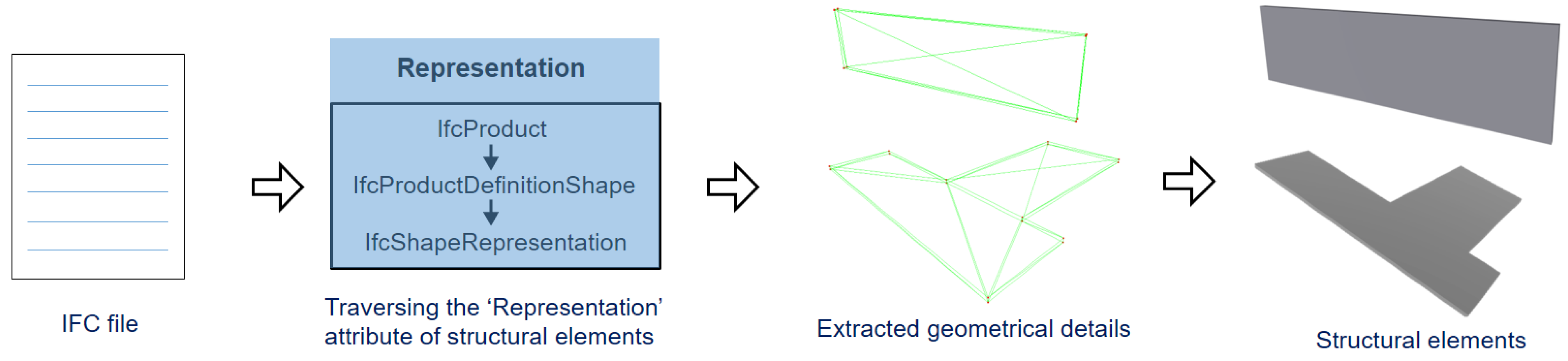
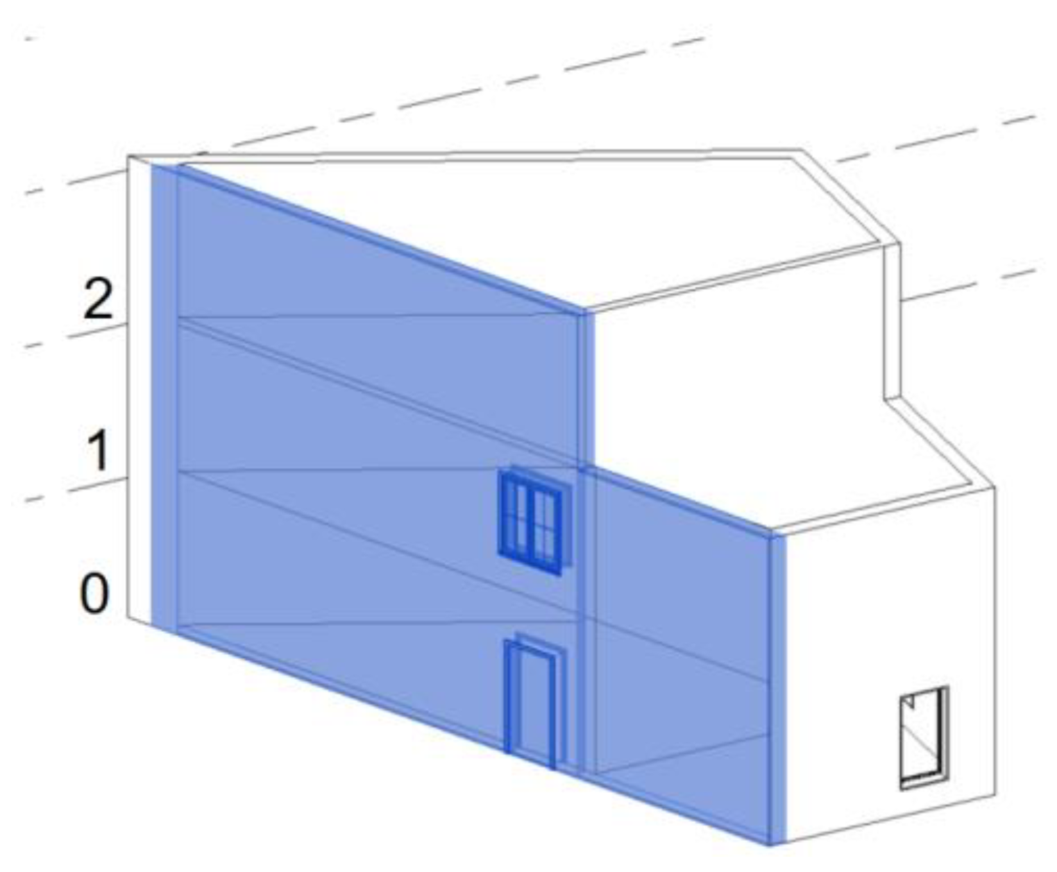
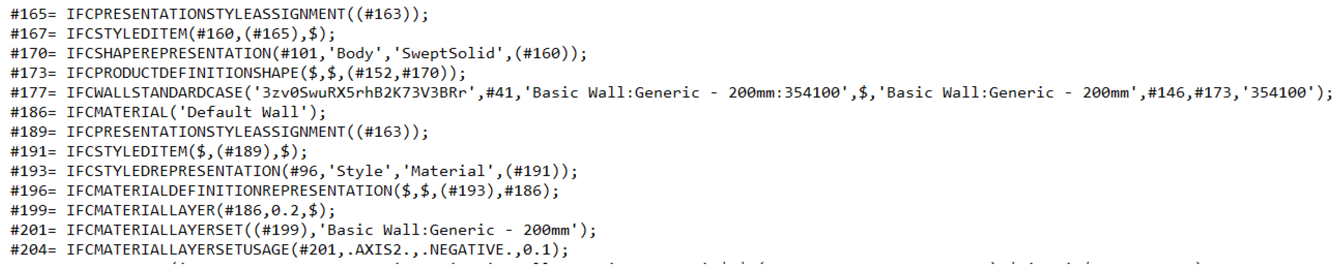
Figure 1 shows an example of the IFC data format in plain text form that contains different entities exchanging various types of information related to building components. To obtain the plane segments from the as-planned model, the mesh model is constructed according to the geometrical details of structural elements from the IFC-based BIM in an automated way, as shown in
Figure 2. The required geometrical shape information, including the vertices and faces from the planar structural elements, like walls and roofs, are taken out from each element by processing their geometric information. The elements are stored in IFC schema under the entity ‘IfcProduct’ with the inheritance (IfcRoot → IfcObjectDefinition → IfcObject → IfcProduct). The geometric information (such as shape, position, direction etc.) of the elements is obtained by traversing the representation attributes. The processed information of these elements in the form of vertices and faces is then used to create their mesh for further processing. Later, the required plane parameters can be directly acquired from the mesh in an accurate and efficient way, without any need of point cloud conversion.
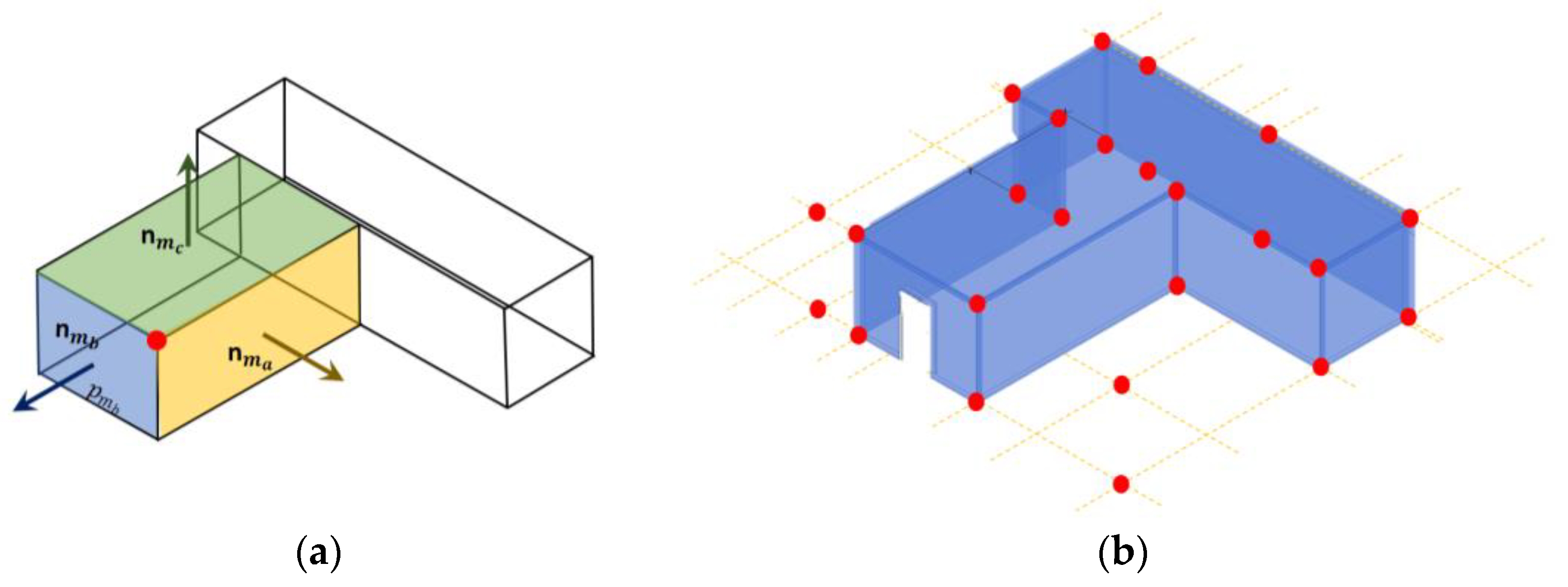
After acquiring the plane segments from both models, all the possible corner points are extracted. The corner point is the unique intersection point between three non-parallel plane segments. For the given plane segments
, and
, with their respective normal vectors
,
, and
, the coordinates of their intersection point (
Figure 3a) can be computed using the given formula:
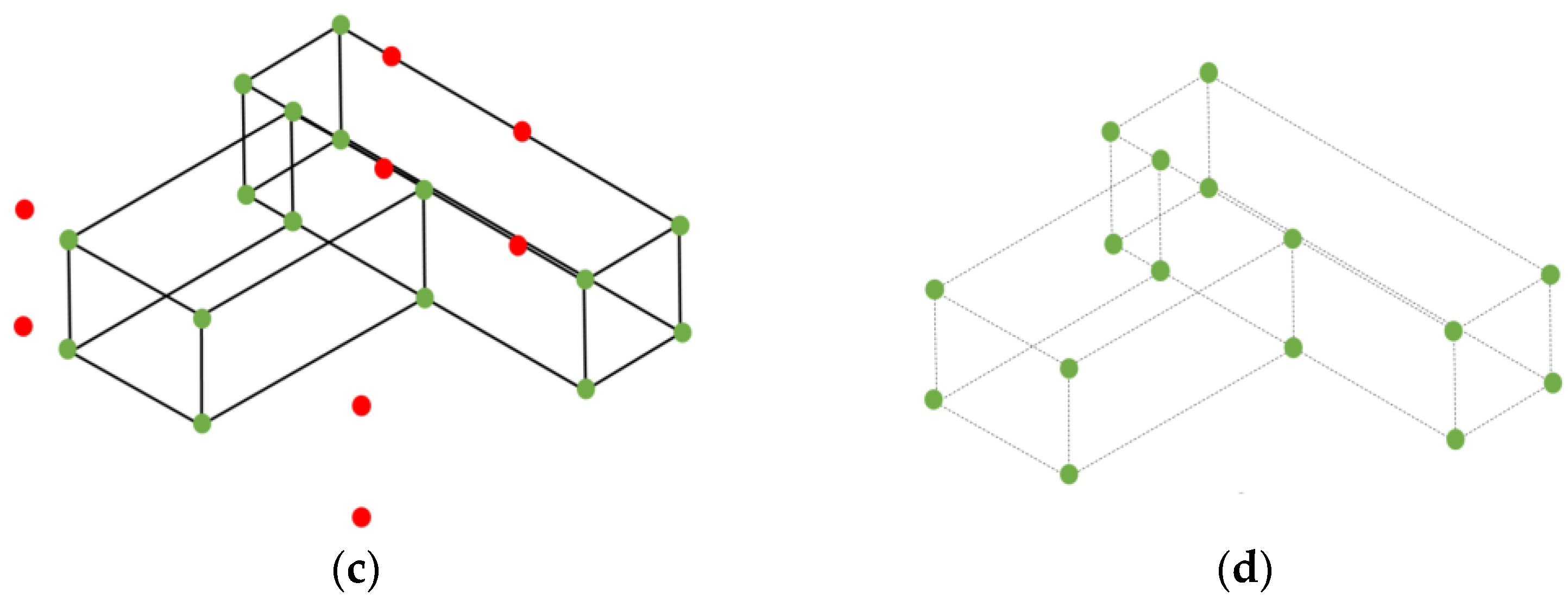
Equation (1) generates the intersection points for the given plane segments based on their plane directions, even if those segments are not actually intersecting. (
Figure 3b) Accordingly, false corner points are also generated that not only increase the quantity of extracted corner points, but, due to the symmetrical positioning of these additional points, can also affect the reliability of the invariant-based matching step. Therefore, a verification is performed that confirms the intersection of the calculated corner point to the actual surface of all three parent plane segments (
Figure 3c). In this study, a k-d tree nearest-neighbor search algorithm is used to verify the intersection of corner points with their respective parent planes with a suitable tolerance radius to accommodate the errors in plane segments. In the end, only the points at the actual corners of intersecting planes (
Figure 3d) are extracted along with the geometrical information of their parent planes.
3.3. Identifying the Potential Matching Corner Points through Geometric Invariants
To identify the matching points between both models, the corner points are pruned using geometric matching criteria to reject the non-matching points based on distance, angle, rotation, and translation invariants. The remaining points that comply with all geometric criteria are termed ‘potential matching points’. These potential matching points are later evaluated in the next step to sort out the matching points.
If the corner points extracted from the as-planned and as-built model are M =
and D =
, with
then their matching corner points can be identified as:
where p is the number of corner points in the as-planned model, q is the number of points in the as-built model,
R, and
are rotation and translation, respectively. Similarly,
is the error in the as-built corner point as a result of the presence of noise and occlusions in the as-built model. In Equation (2),
is the matching point of
with an error
in the
i-th correspondence according to the rigid transformation parameters
R and
t.
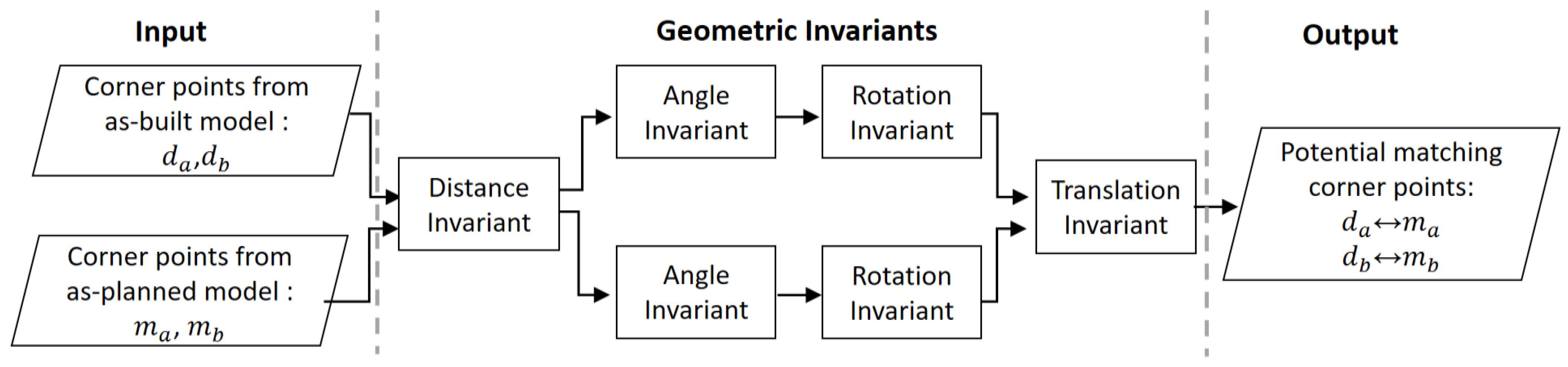
The identification of matching points is performed in a cycle where the two corner points from both models are assessed for matching simultaneously through a series of different geometric invariants in a specified combination. For example, two corner pointsfrom the as-built model are compared with the respective corresponding corner points { from an as-planned model in a particular cycle, and if they are congruent to all the invariants, only then they are withheld as potentially matching; otherwise, they are rejected. In the next cycle, two different corner points from both models are compared. Each cycle can either reject or withhold the pairs of two corner points as potential matching corner points to eventually identify the possible pairs in the end.
Figure 4 shows the processing flow for the assessment of the geometric invariants for one cycle. The processing of two sets of corner points, instead of one, gives the opportunity to individually compare both sets with each other (in the first and last step) in addition to analyzing the match of corresponding points in each set (in the second and third step) in each scrutiny-based cycle. Overall, this pairwise processing of corner points in an invariant-based step-wise combination is designed to increase the prospects of identifying the matching corner points in a highly optimized way. The details of geometric invariants to identify the potential matching points are as follows:
3.3.1. Distance Invariant
The distance invariant is based on the characteristic that, if the two particular points from both models are matching points, then the distance between them should also be the same. Mathematically, given any two points {
in M and their matching points {
in D, where
, the relative distance of these two points and their matching points from Equation (1) becomes:
In above equations,
denotes the Euclidean norm in
. If c is the constant that represents the maximum allowed error on the distance, hence that
c >
, then the Equation (4) can be written to reject the non-matching points:
As the relative distance between corner points is invariant with respect to rotation ‘R’ and translation ‘t’, it provides the possibility to initially probe the pair of corner points for matching without computing their transformation parameters.
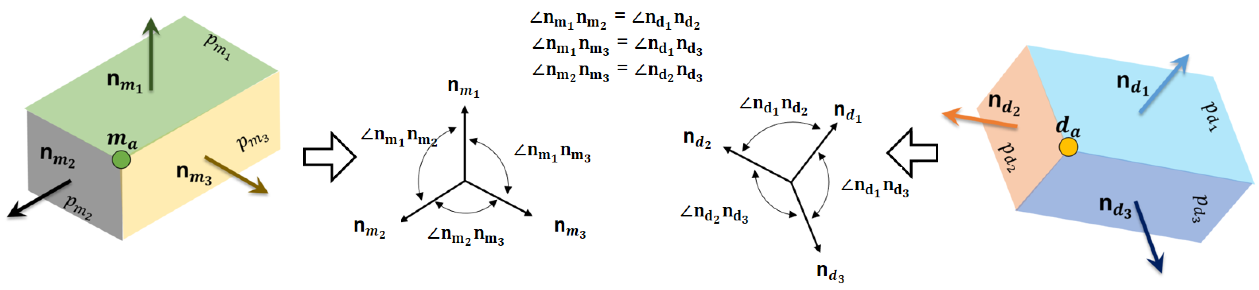
3.3.2. Angle Invariant
The angle invariant is based on the geometric invariant that the corresponding parent plane segments of matching corner points should have the same relative angles with each other. Each corner point is constructed from three parent plane segments with their respective normals. With a suitable tolerance, the angles between the corresponding parent plane segments for both potential matching corner points are probed using their plane normals, as demonstrated in
Figure 5.
3.3.3. Rotation Invariant
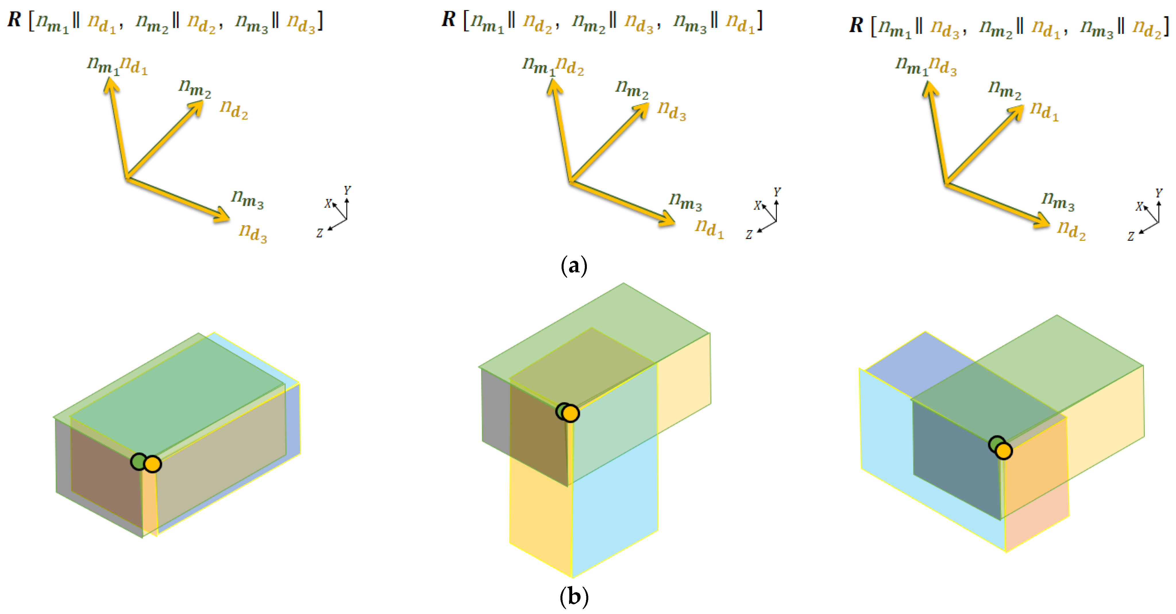
If not rejected in the previous steps, both pairs of potential points are assessed to find their corresponding transformation with the correct rotation. It is based on the invariant that the transformation obtained from potential matching corner points with correct rotation should fit their respective corresponding parent plane segments.
To find the transformation of any potential matching corner points, the direction of their corresponding parent plane segments can be utilized to find out the rotation matrix and then the translation can be computed directly from the points. However, the estimation of correct transformation demands the determining the correct rotation matrix and this requires the identification of the respective corresponding segments. Most buildings have orthogonal geometries with perpendicular plane segments; therefore, the correspondence of plane segments cannot be truly determined based solely on their relative angles. To illustrate this, some examples of rotation matrices (
) resulting from the alignment of the corresponding plane’s normal in different combinations ‘
r’ are shown in
Figure 6a while the visualization of the transformation obtained from the respective rotation matrices on the as-built model relative to the as-planned model is shown in
Figure 6b.
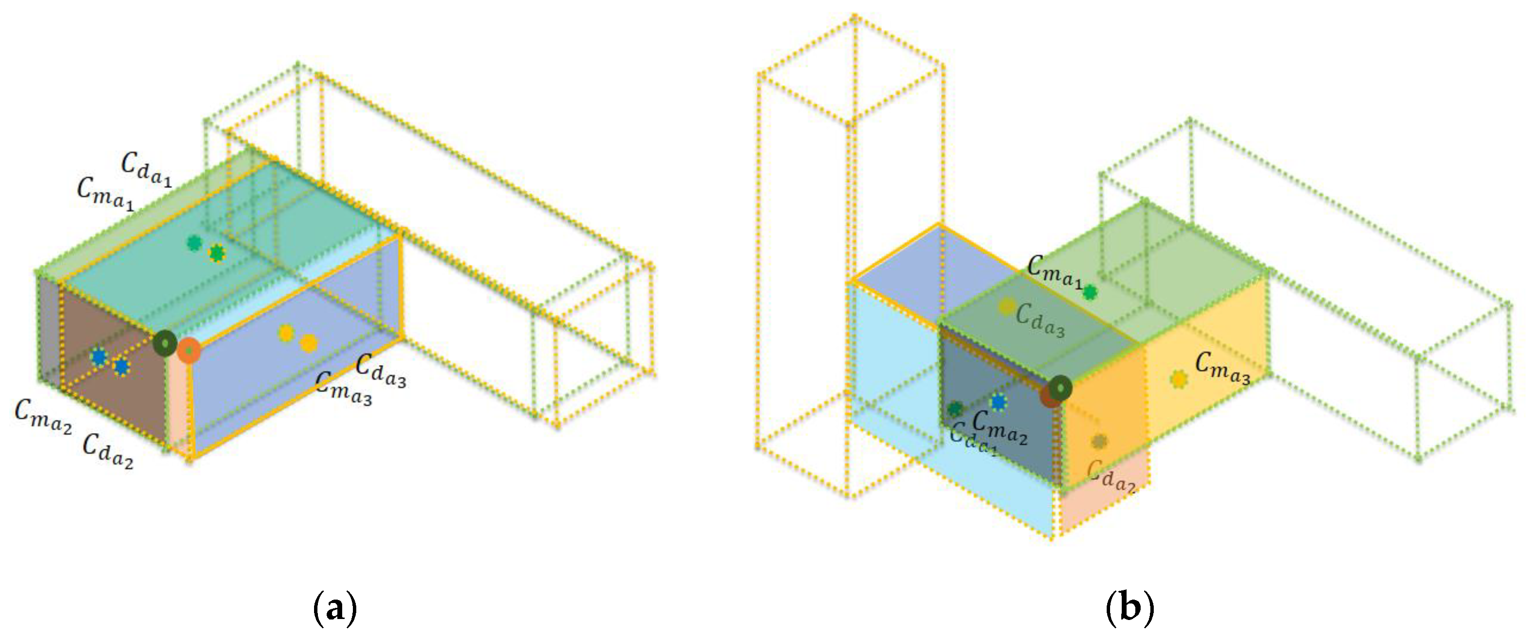
To solve this issue, transformation is determined for potential matching points with possible rotation matrices according to all the corresponding combination of parent plane segments and then evaluated in terms of their plane segment centroids to confirm their geometrical coincidence after transformation. For example, the rotation matrix (
) is determined for individual potential matching corner points (
) by aligning the corresponding direction of plane segments based on the correspondence combination ‘
r’ while the translation (
) is computed from the corner points. For all the possible rotation matrices with their respective translations for all the combinations, the projection of the average centroid of the parent plane segments from the as-planned and transformed as-built corner points are compared using Equations (6) and (7) for both pairs of points, respectively.
In the ideal case, the average centroids {
of the plane segment from both models should project into each other with the correct rotation
(
Figure 7a) as compared to the incorrect rotations (
Figure 7b). However, due to errors in the as-built plane segments, the projections may have slight deviations. Therefore, the rotation matrix allowing the projections to be nearest to each other is considered to be the most likely rotation matrix among the other matrices. The underlying reason is that it is the only rotation matrix obtained with the correspondence which permits the simultaneous fitting/coincidence of all the matching plane segments with each other. At the end of this step, the individual rotation matrices (
for both pairs of potential matching points that are later processed in next stage are computed.
3.3.4. Translation Invariant
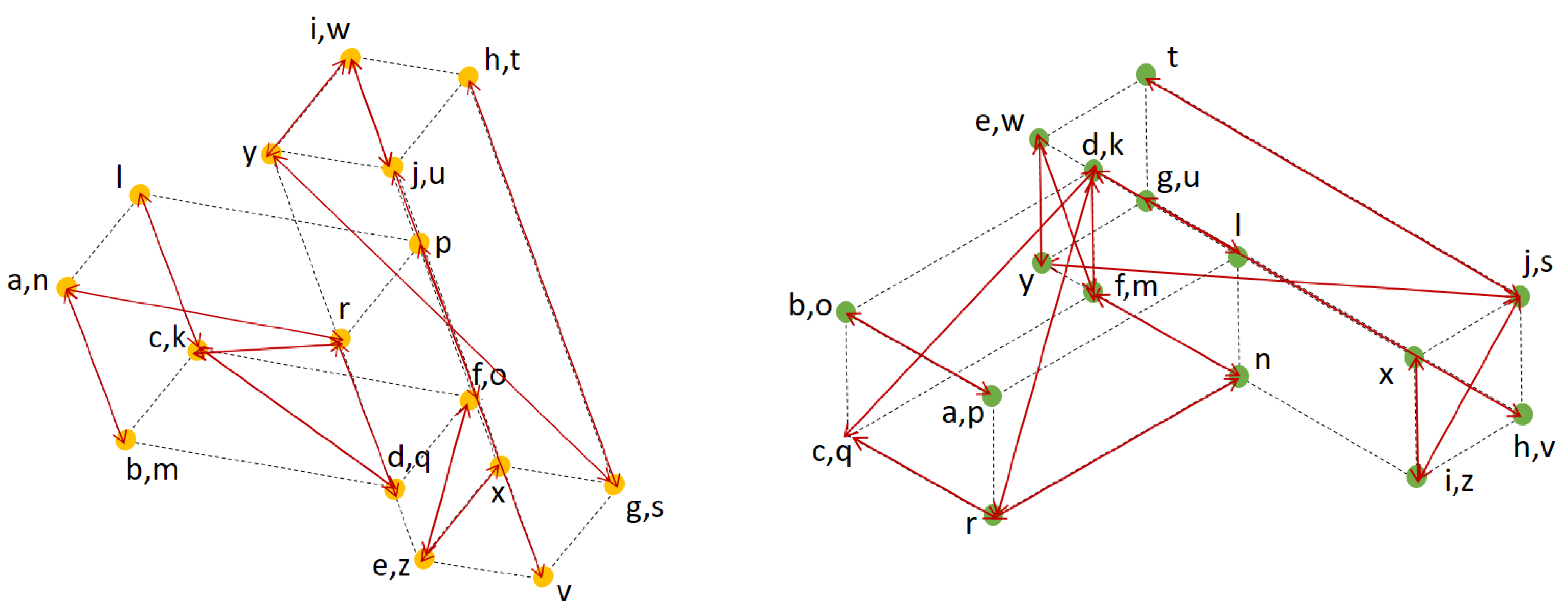
Finally, the transformation parameters calculated from both potential matching points are compared. It is based on the invariant that all the matching points should have the same rotation matrix and translation. If any of the transformation parameters from both pairs of potential matchings points are not the same, then they are rejected.
Mathematically, any corner point
corresponding to its matching point
rotated with rotation matrix
has the translation
=
. Similarly, in the case of potential matching corner points, the two corner points {
in M corresponding to their matching points {
in D, with respective rotation matrices {
should have the same rotation, such that
, and the same translation, which satisfies the following:
In the above equation, c is the constant confirming
with a suitable value assigned according to the errors in as-built plane segments.
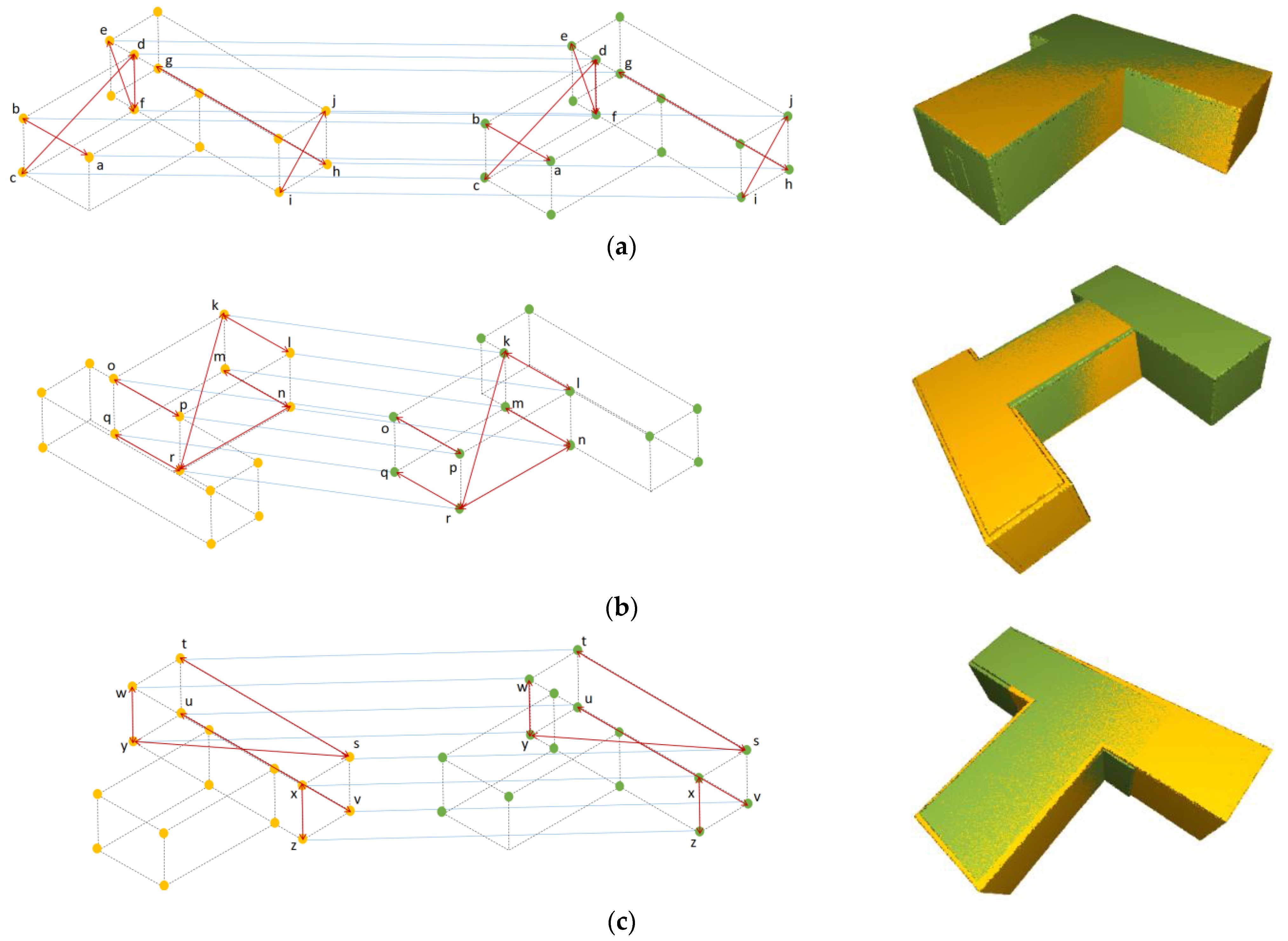
Figure 8 indicates the potential matching corner points, indicated with same label in both models, obtained after consenting to all the geometrical invariants.
The combinations of invariants that sequentially process the pairs of candidate corner points for matching are arranged to identify the potential matching corner points with less possible computation. The first step rejects the non-matching pairs without the need to calculate other parameters, thus reducing the processing time of the succeeding steps. The non-rejected pairs are further probed in a step-wise arrangement using the required parameters that were computed in the preceding step. Furthermore, the identification of potential corner points can be performed using all the extracted corner points from both models. However, the processing time can be increased exponentially in the case of a high number of corner points and can affect the time efficiency. Therefore, the two corner points from both models are randomly picked in each cycle using RANSAC with a defined number of cycles to ensure robustness during the current stage of identifying the potential matching points using geometric invariants.
3.4. Evaluating the Transformations of Potential Matching Corner Points
The identified potential matching corner points include the matching corner points with correct transformation, but there is a possibility that some non-matching points with incorrect transformation may be included as well, as evident in
Figure 8. Non-matching corner points may have passed the identification due to the possible symmetries in the models. Therefore, all the remaining potential matching points are re-evaluated to find the correct or most likely matching corner points and transformations in two steps: (1) removal of duplicates and clustering of the remaining potential matching points according to their transformation parameters and (2) selection of the cluster with the correct transformation parameters.
3.4.1. Removing the Duplicates and Clustering the Potential Matching Corner Points
The potential matching corner points, identified in the last step, may contain duplicates due to the possibility of their identification in many pairs as a result of the RANSAC pairwise processing. There is a possibility that the duplicate pairs of potential corner points can be picked during RANSAC random selection. These duplicates are discarded by removing the other potential matching corner points having the same parent planes.
After removing the duplicates, potential matching corner points are grouped according to their transformation parameters. The translation vector
=
is dependent on the rotation matrix; hence, it is unlikely that potential matching points with different rotation matrices have the same translation vectors. Therefore, the translation vectors of the points can be utilized to differentiate their transformation parameters. To allocate potential matching corner points to a cluster with translation
, the candidate potential matching corner points with
should have the same translation with a suitable tolerance c, as represented in Equation (9).
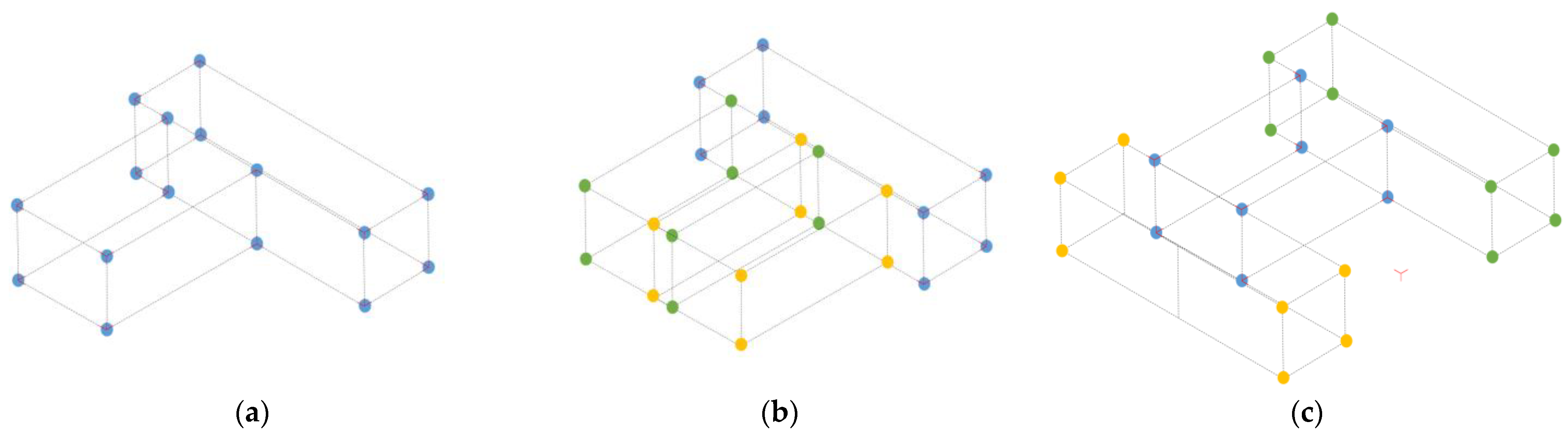
Figure 9 represents the different potential matching points [a, b, c, …, y, z], clustered according to their transformations where it is apparent that the potential matching points in each cluster have the same translations (blue line).
3.4.2. Finding the Cluster with the Correct Transformation
To reduce computation time—instead of evaluating the individual potential matching corner points—the evaluation is performed directly on the clusters based on the two invariants to allow the simultaneous identification of the matching corners. According to the first invariant, the correct transformation aligns all (or the majority of) the corner points from both models. The second invariant advances that, if the aligned corner points in the correct transformation are matching, their corresponding parent planes should be parallel as well. Based on these two invariants as indicators of the correct registration, all the clusters, with their transformations, are evaluated.
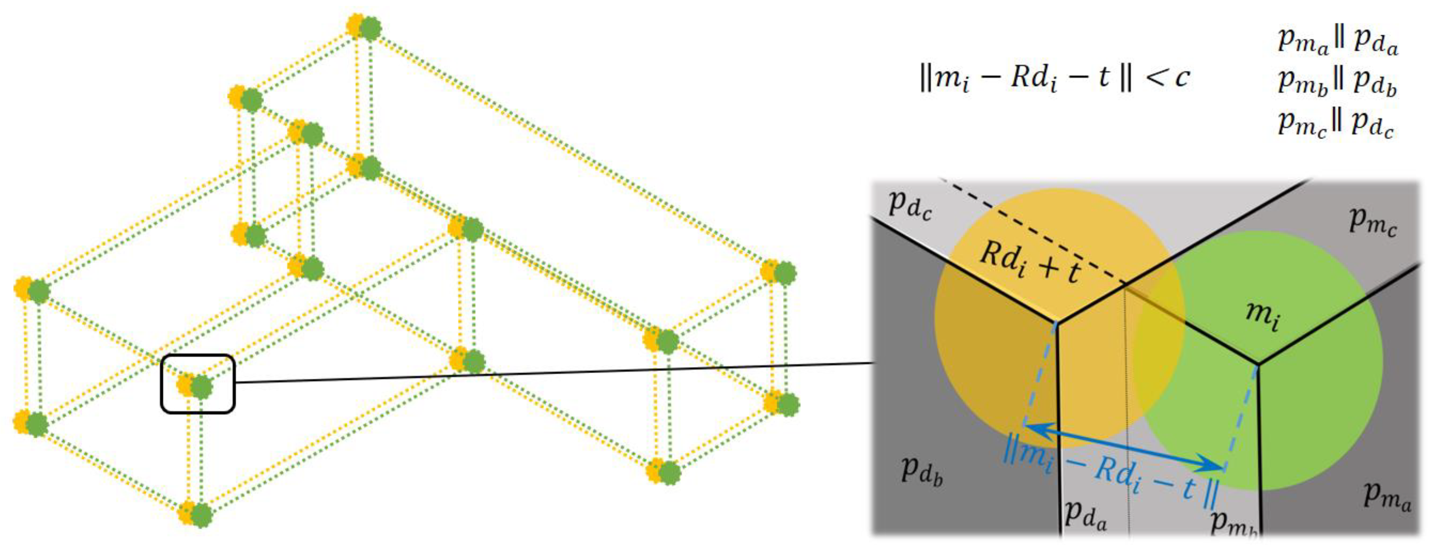
Initially, all the corresponding corner points according to each transformation from the clusters are recognized. The transformation parameters from the respective clusters are applied to the original as-built corner points to project them into as-planned points. Ideally, corresponding points with the same parent plane segments from both models should be aligned with each other in the case of correct transformations. However, due to the presence of errors in the as-built plane segments, the projection of corresponding corner points may not be exactly aligned but located near to each other. Therefore, neighboring corner points from both models having corresponding parallel parent plane segments are determined with a suitable tolerance, by means of k-d tree and the angles between the normals of the corresponding parent plane segments.
Figure 10 shows a corner point
from the as-built model transformed with rotation
and translation
. Its distance to a neighboring point
from the as-planned model is less than the tolerance
c, and both points have parallel parent plane segments after transformation; hence, they are considered to be aligned corner points.
It is obvious in
Figure 10 that some of the aligned corner points with parallel corresponding parent plane segments, according to the transformation of each cluster, are already present in the cluster along with other additional aligned corner points. The additional points are the potential matching points that have a similar transformation if computed. However, they were not identified previously due to the random selection of corner points from both models using RANSAC. Therefore, the current procedure enables their complete detection. The additional potential matching points are detected at the current stage because the complete identification of all the potential matching points in the previous stage is computationally expensive. The random identification ensures the minimum computation and outputs sufficient potential matching points that include at least one matching point whose transformation is enough to detect the other matching points at this present stage. Overall, this approach allows the robustness in the proposed method with high reliability.
Finally, the cluster with the transformation having the highest number of aligned corner points is considered to be the correct transformation while the respective aligned points are finalized as matching corner points.
Figure 11 demonstrates the aligned points in both models according to the transformation of different clusters. The cluster transformation in
Figure 11a has the highest aligned points as compared to others; hence, it is finalized as a cluster with matching corner points having correct transformation.
3.5. Calculating the Most Optimal Transformation from Matching Corner Points/Cluster
After sorting out the cluster with highest number of matching corner points, the individual transformation parameters of each corner point are assessed to find the most optimal transformation. The rotation
and translation
among the other respective rotation {
and translation {
parameters of clusters that align the corner points from both models with relatively more precise fitting, e.g., with less error, are finalized as the optimal transformation parameter, using Equations (10) and (11).
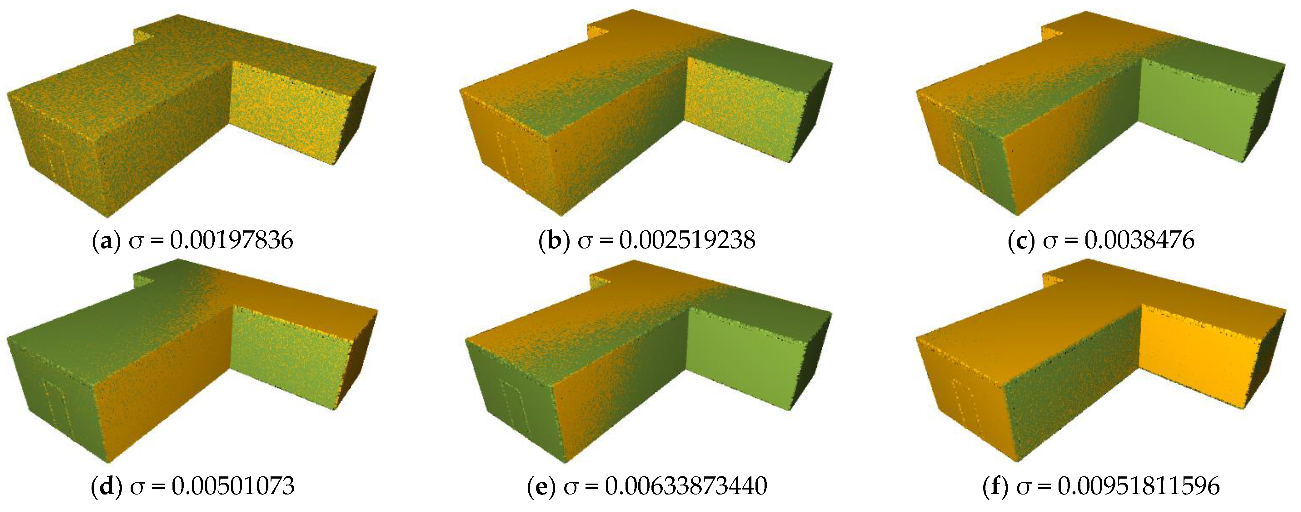
In
Figure 12, the models registered with transformation parameters corresponding to their error values are shown and
Figure 12a indicates the optimal transformation (lowest error). It is evident that the optimal transformation parameter offers the relatively highest overlapping of models.
3.6. Identifying the Matching Planes from Matching Corner Points (Optional)
The construction project monitoring requires the progress estimation of building components that are represented by plane segments. The individual identification of matching plane segments is essential for an effective monitoring process. Normally, the matching planes can be easily identified using the criteria that the matching plane segments are parallel and fit with each other after registration. As an additional and reliable alternative, the utilization of corner points along with the semantic information of their parent plane segments in the proposed method enables the identification of plane segments as well. Generally, each plane segment is present as a parent plane segment in more than one corner point, with a maximum of four corner points. Therefore, after computing the transformation from the matched corner points, likewise, the matching plane segments can also be obtained by verifying their required presence in their corresponding multiple matching points.
4. Results and Discussion
The methodology was tested on different datasets presenting various challenges based on their geometrical shape. The datasets include two simulated (A1 and A2) and two real-life datasets (R1 and R2).
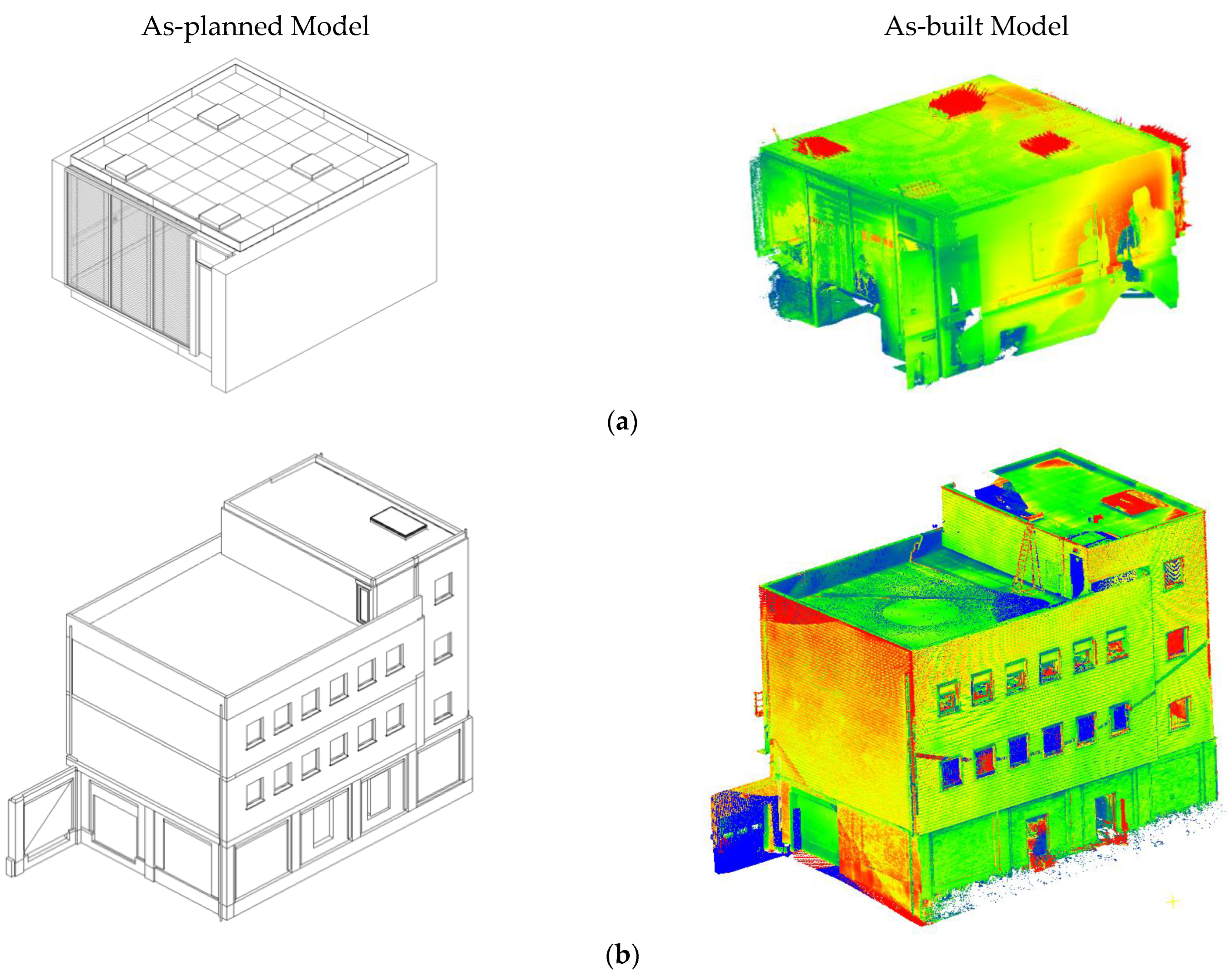
The simulated datasets were artificially designed to represent the building models with different structural compositions for testing, as shown in
Figure 13. Using such datasets allowed for the assessment of the theoretical foundation of the proposed method, without effect of errors typical for real life situations. The BIM models in IFC format were used as as-planned models, whereas randomly transformed models in point cloud format was used as as-built models. Both simulated models have nine plane segments; however, the first model represents a single-floor building while the second one represents a triple-floor building.
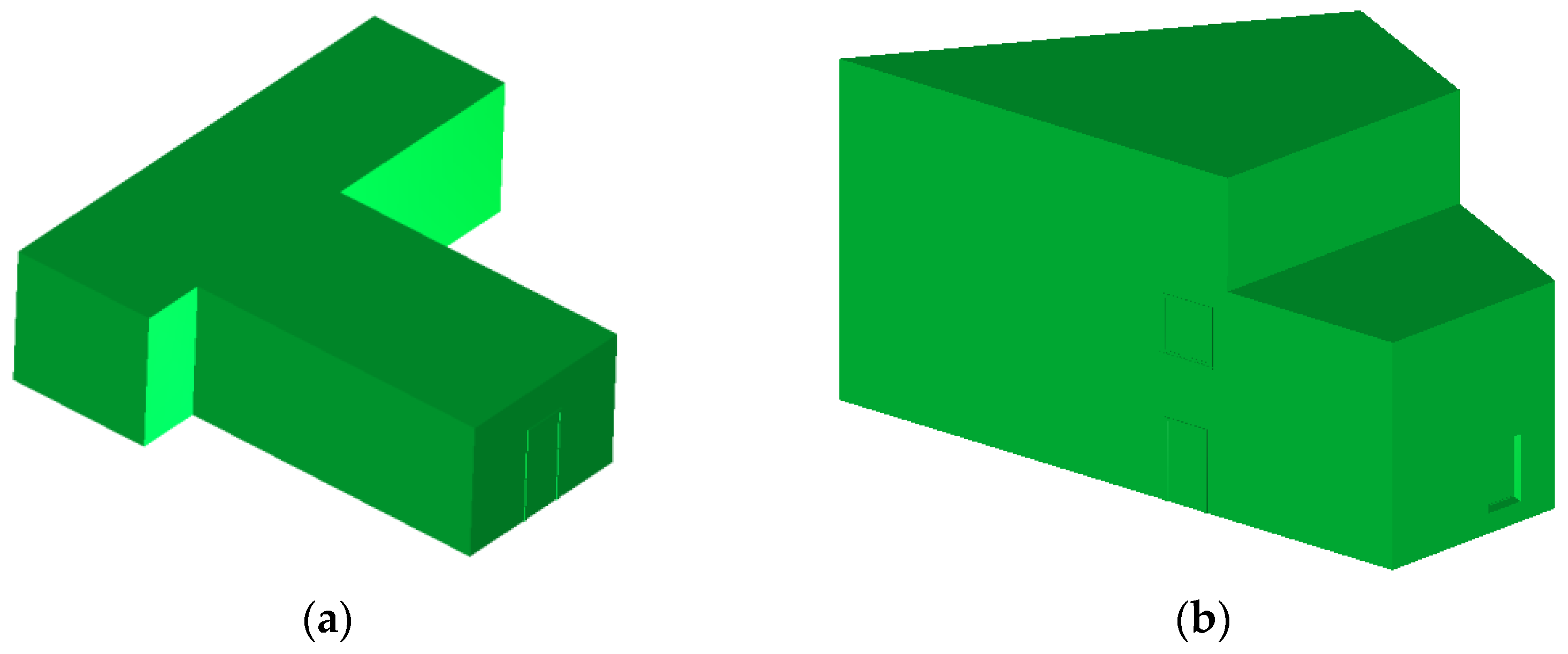
The real-life datasets contain the BIM and as-built models of two building projects. The as-built models were acquired by means of laser scanning. The datasets represent a conference room (R1) and a large educational building (R2), as shown in
Figure 14a,b, respectively. It is worth noting that both the real-life datasets were already used in other research [
70,
71,
72]. Using these real-life datasets to assess the proposed method allows the evaluation of its performance and robustness in the case of the presence of occlusions, noise, and other errors typically present in as-built point clouds.
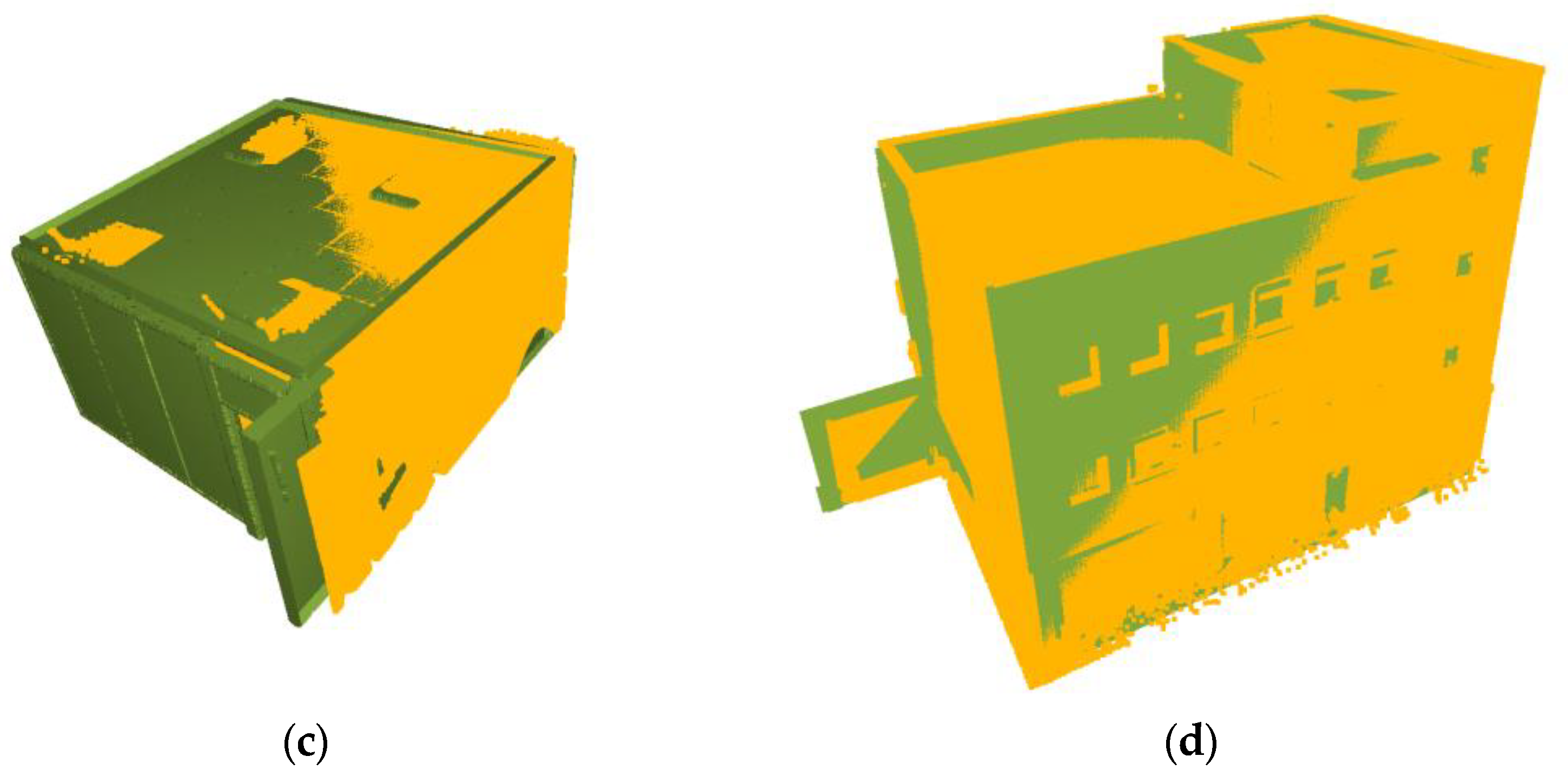
During the testing, the initial down-sampling of the as-built models was performed with a voxel size of 0.2 m and, later, RANSAC-based-plane segmentation was performed to obtain as-built plane segments. Similarly, the number of RANSAC iterations to randomly select the two corner points from both models for identification of potential matching points was limited to 5000. Furthermore, according to errors in the as-built model of each dataset, a suitable tolerance value was used to verify the geometric invariants. The proposed method successfully registered all the datasets, as shown in
Figure 15. A detailed analysis was also performed to evaluate the registration accuracy and explore the limitations.
To evaluate the registration accuracy, the root-means-square errors (RMSE) were computed. Furthermore, the transformed models were also compared with their ground truth models as RMSE is not sufficient as an indicator of registration accuracy [
10]. The ground truth models were the same as the as-planned models for the simulated datasets; however, in the case of the real-life datasets, the transformed models after fine registration were used as ground truth. The rotation error in degrees and the translation error in mm for each dataset were calculated as additional evaluating metrics using Equations (12) and (13), respectively.
In the above equations,
and
represent the quaternion rotation angles and translation vector of ground truth, whereas
and
are the quaternion rotation angles and translation vector of the transformed model. The evaluation parameters, listed in the
Table 1, indicate an overall good accuracy as a coarse registration method. The method registered not only the simulated datasets but also the real-life datasets with higher accuracy. Furthermore, the registration results were also compared with our previous plane-based method [
66], as shown in the
Table 1, where it is evident that the proposed method registered all the datasets with more accuracy. The higher accuracy can be attributed to the approach of the proposed method that ensures the detection of all the matching corner points to compute the most accurate transformation parameter from them.
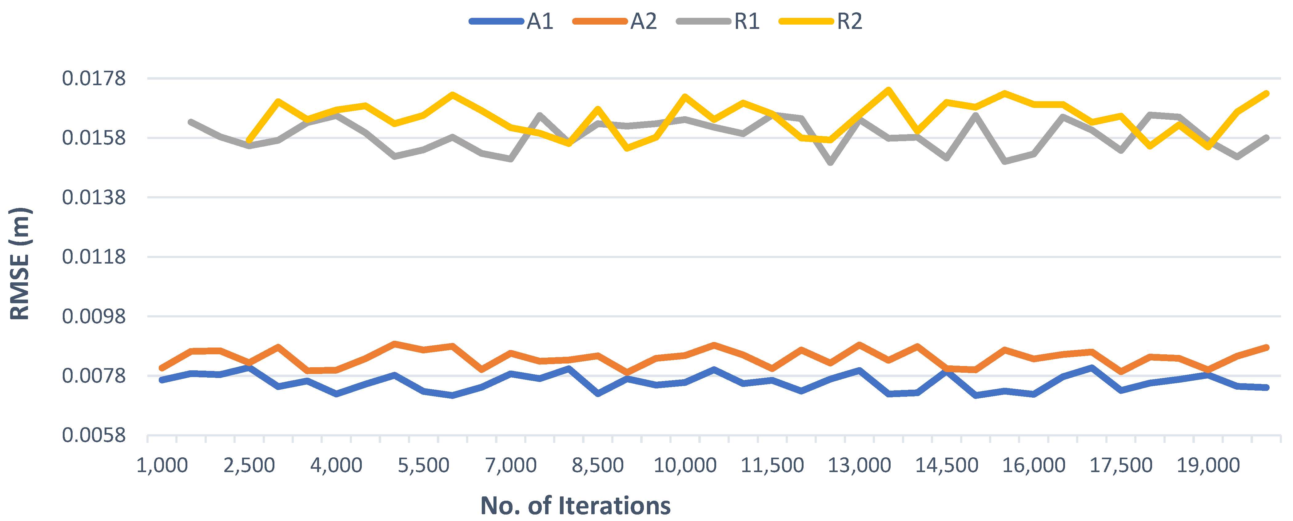
The proposed method is RANSAC-dependent to ensure robustness, so the number of iterations could have an influence on the success. Although increasing the number of iterations results in more potential matching points with a cost of higher processing, this does not improve the registration accuracy (as shown in
Figure 16) as the method already ensures the highest accuracy by detecting the remaining matching points after selecting the most optimal cluster in the third step. Generally, the method can only fail if the potential matching corner points obtained in stage 2 do not include any actual matching point, which can happen if the number of RANSAC iterations is too low. During testing, the method failed for dataset R1 and R2 prior to a number of iterations of 1500 and 2500, respectively. By increasing the number of iterations, this problem was resolved. In our results, 5000 iterations were found to be sufficient for both robustness and successful execution of the proposed method for all tested datasets.
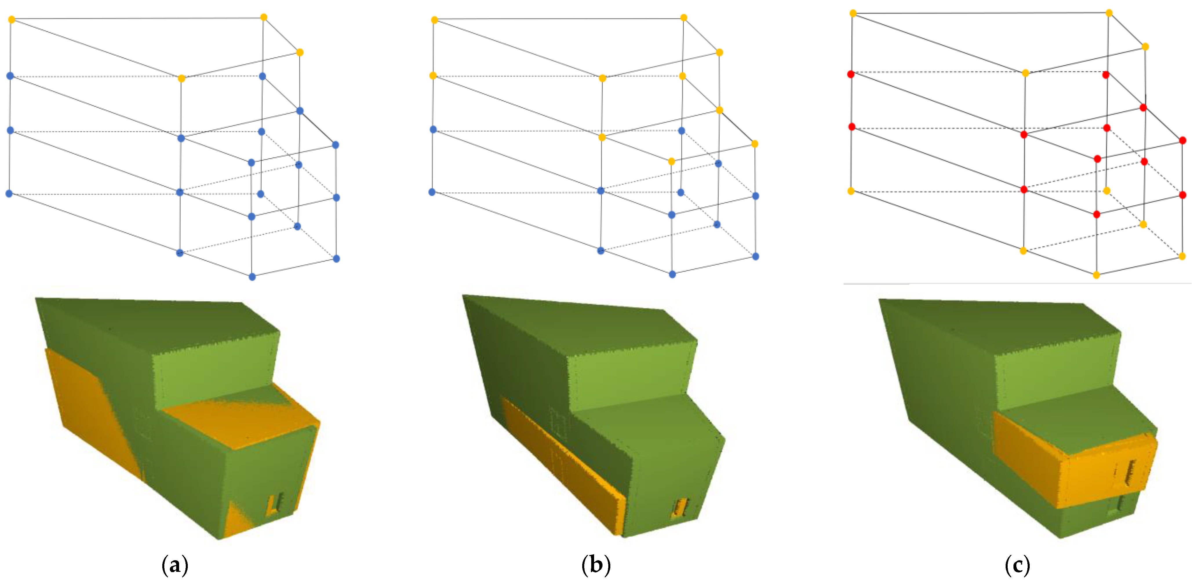
The potential matching points are identified using a series of geometric invariants to try to ensure that only the actual matching corner points are detected; however, geometrical symmetry in the building can still lead to the selection of non-matching points. To further explore this problem concerning construction progress monitoring, the proposed method was also tested for partially built buildings to analyze its success. For this purpose, two additional as-built models derived from dataset A2 (
Figure 17), representing the completion of the first and second floor, were created.
The experimentation validated the successful registration of the as-built model with two floors completed as shown in
Figure 18a; however, the registration success of the remaining model with the single model was inconsistent. Sometimes registration was successful, but other times there was some translation error, as shown with the registered models in
Figure 18b,c. The reason can be attributed to the fact that there was a lack of distinct points in both models. Hence, the proposed methodology finalized the two transformation clusters with equal number of corresponding corner points due to symmetrical positions of corner points at ground zero, first, and second, as demonstrated with the corner points in
Figure 18b,c. However, in the case of the as-built model with two floors completed, the points are also the same and symmetrical, but the transformation cluster with maximum corresponding points is identified. The same happened with the fully completed as-built model (dataset A2). Therefore, it can be concluded that the proposed method works well for incomplete buildings not only with non-symmetric corner points but also with symmetric points if not all the as-built points form the symmetry with additional as-planned points.
The presence of symmetrical corner points in the building models challenges the registration due to similar geometrical parameters. However, the presence of a few discriminatory corner points can support the identification of correct transformation. Hence, the proposed method may fail in buildings with a symmetrical geometry; however, the presence of few distinct planar structures in the buildings can resolve this limitation. To solve this limitation in future research, the same matching strategy for complicated structures in the building can be developed if required.


