Abstract
This article presents the first results obtained from the use of high-resolution images from the SAR-X sensor of the PAZ satellite platform. These are in result of the application of various radar image-treatment techniques, with which we wanted to carry out a non-invasive exploration of areas of the archaeological site of Clunia (Burgos, Spain). These areas were analyzed and contrasted with other sources from high-resolution multispectral images (TripleSat), or from digital surface models obtained from Laser Imaging Detection and Ranging (LiDAR) data from the National Plan for Aerial Orthophotography (PNOA), and treated with image enhancement functions (Relief Visualization Tools (RVT)). Moreover, they were compared with multispectral images created from the Infrared Red Blue (IRRB) data contained in the same LiDAR points.
1. Introduction
In this article, we mainly present results of the exploration and analysis of a set of Synthetic-aperture radar (SAR) images from the Spanish PAZ satellite applied to non-invasive archaeological prospecting. The works consisted of the generation of images from SAR data and comparing the results with those received from the exploitation of other sources, such as multispectral images (National Plan for Aerial Orthophotograph: PNOA, TripleSat) and LiDAR. In principle, our project—Application of Radar images of the PAZ Satellite in the Detection of Archaeological Remains (ARQPAZ, Project AO-001-018)—focused on the archaeological site of La Clunia, (Figure 1), which is located near the town of Peñalba de Castro (Burgos, Spain), on a hill called El Alto de Castro.
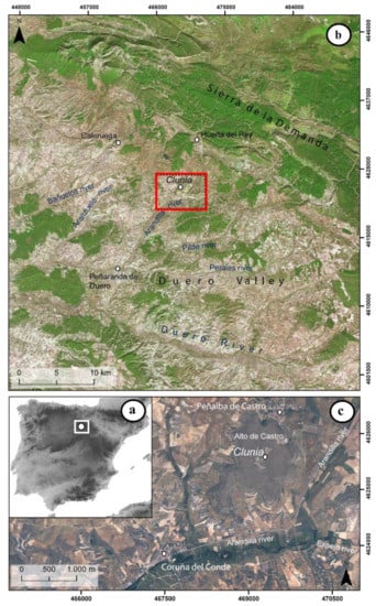
Figure 1.
Location of Clunia. Sources: National Geographic Institute (IGN), National Plan for Aerial Orthophotography (PNOA), Maximum resolution (20 cm). (a) Location of Clunia in Spain (b) Location of Clunia in the Douro Valley (c) Clunia and the Alto del Castro.
We know from Salustio (Hist., 2, 93), Tito Livio (Periocas, XCII), Plutarco (Sertorio, 9), or Floro (2.10.9) the first references to the pre-Roman Celtiberian city of Clunia, connected to the Sertorian wars. The sources do not make it clear if it was located in the nearby hills, or at some point at its final location, after it was founded by the Romans. This foundation would occur sometime between the end of the rule of Augustus, and that of Tiberius. Clunia would have an important role during the events of 68 AD, receiving from Galba the epithet of Sulpicia, becoming the capital of Conventus within the province of Tarraconense. The hill where the site is located has an area of 1.2 km2, of which only 3% has been excavated since the second half of the 19th century.
However, the excavated remains correspond to large public spaces such as the theatre, the forum, thermal complexes (Los Arcos), and large private spaces such as the so-called Casa Taracena. Furthermore, the urban organization of the city does not correspond to a homogeneous structure, but on the contrary, the provisions of both large public and private constructions would add up to four possible different orientations (Figure 2).
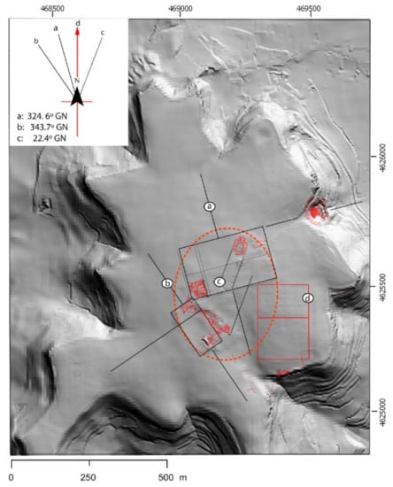
Figure 2.
The different urban orientations of the city of Clunia: (a) Structure based on the orientation of the theatre and Taracena House; (b) Orientation based on the orientation of the forum; (c) Orientation based on the set of Termas de los Arcos; (d) orientation detected in [1]. Source: Hill shading from LiDAR DEM (5 m/pixel) PNOA.
These peculiar characteristics, together with the great extension of the site and the economic consequences of the 2008 financial crisis, have led to the need to explore the hill with non-invasive methods mainly associated with remote sensing. Previous work by our team focused on exploring the possibilities of analysing infrared images and LiDAR point clouds obtained by the state through the National Plan for Aerial Orthophotography (PNOA) and SPOT-5 multispectral images. These were focused on a single area of the archaeological site and were combined with geophysical prospecting applied in selected sectors by the SOT (Catalan for “Hole”) —Archaeological Survey Company. For this survey, electromagnetic technique, using the Grad601 fluxgate gradiometer manufactured by the Bartington Instruments Ltd. company, was applied in a very specific sector. The geophysical survey was carried out on a series of three grids measuring 20 × 20 metres on each side, each with N–S orientation; thus, forming a total area of 20 × 60 metres.
This work allowed, among other results, to determine one of the aforementioned four orientations that would structure the urban organization of the city [1] (pp. 142–143).
On the other hand, the first instrumental uses of SAR started being used in 1978, but it was not until the mid-1980s that the data from SIR A and SIR B were applied in geo-archaeological studies associated with ancient riverbeds [2,3], ancient cities such as Ubar (Oman) [4], and the location of Mayan irrigation canals [5,6]. However, these investigations, due to the spatial resolution of the sensors at the beginning of the new century, were limited to still-preserved monuments, cultural landscapes, paleo-landscapes, and canal systems. Since the launch of the TerraSAR-X and COSMO-SkyMed platforms in 2007, it has been possible to access high-resolution data at the scale of 1 m from Very High Resolution (VHR) SAR sensors, applying them to the detection of archaeological remains. However, the penetration capacity of these sensors in the X band is very limited, as compared to others that work in the L and C bands [7] (pp. 71–75). It should be added that PAZ, such as TerraSAR-X, works on the X band.
The effectiveness of the TerraSAR-X image analysis applied to large old buried infrastructures was shown in the work prepared by Monterroso and Martinez [8]. These authors located sections of the Roman road near the ancient Roman city of Mellaria (Cordoba, Spain) under cereal fields and in conditions of high humidity. On the other hand, they also found remains of medieval roads, paved with gravel and built without elements that would allow their drainage. This caused the accumulated humidity to be transmitted to the soils superimposed on said infrastructures. As conclusions, they indicated that SAR data acquisition in high humidity and rainfall conditions in cultivated fields revealed better potentials; in non-cropped landscapes, however, according to the authors, thermal and RGB photography analyses were better.
The PAZ satellite, equipped with the SAR sensor, was put into orbit in February 2018 by Hisdesat [9]. Specifically, the instruments consist of an X-Band SAR radar which allows working in four basic image modes—Spotlight, HR (High Resolution) Spotlight, StripMap, and ScanSAR—with various polarizations—single and dual. After the start of its operation, a call for an opportunity offer was opened by the National Institute of Aerospace Technology (INTA). This allowed us to access a set of SAR X-Band images to test its potential as an exploratory tool. We worked specifically with the Spotlight product, which has a resolution of 1.25 m/pixel.
Furthermore, the importance of the use of various non-invasive techniques for the detection of archaeological features in the landscape should be noted. There is varied literature on this topic, where we can see examples such as the use of multiple vegetation indices applied to hyperspectral images, and combined with geophysical surveys, which has allowed the highlighting of crop marks in the buried Roman remains of Carnuntum (Austria), the underground structures of Selinunte in the south of Italy, and the buried street relics of Pherai (Velestino) in central Greece [10]. Other cases combining non-invasive techniques applied to underwater environments, such as multi-beam echo sounder (MBES), and sub-bottom profilers (SBPs), can be found in the reconstruction of a medieval harbour using hydro-acoustics, 3D shallow seismic and underwater photogrammetry in the Sothern part of the Baltic Sea [11].
Finally, the ARQPAZ project aims to study the behaviour of radar images in three different environments associated with three archaeological sites, in which we have previously worked with non-invasive exploratory investigations: Oxirrinco [12], Cosa [13], and finally—Clunia. This work presents the results of the first evaluation of the possibilities of the SAR-X images of PAZ in the archaeological site of Clunia.
2. Materials and Methods Used
Our project focused on the following digital sources of information (Table 1): SAR images of PAZ, LiDAR point clouds of the National Geographic Institute (IGN) with information from IRRB bands, images of old NIRGB (Near Infrared Green Blue) flights of the National Plan for Aerial Orthophotography (PNOA, IGN), and TripleSat multispectral imaging.

Table 1.
Technical information on the data sources used.
The SAR images, with HH polarization, were captured during the months of July to October 2019 and 2020, and the LiDAR point clouds correspond to 2010 and 2011. On the other hand, we also wanted to contrast the results with high-resolution multispectral images. In this case, we chose images captured by the TripleSat 2 satellite, which is part of a network together with two other satellites with the same characteristics. The TripleSat satellite, put into orbit in 2015 [14], provides a panchromatic band at 0.8 m/pixel resolution, and four bands at 3.2 m/pixel (NIR, Red, Blue, Green). The acquisition of these multispectral images is tried to coincide with the summer and autumn periods, corresponding to 2016 and 2017.
In the case of the PNOA IRGB photographs, after careful analysis, we used in our work those corresponding to the years 2007, 2009, and 2011. These flights were conducted during the summer periods, in 2009 in July, and in 2011—in June/July). We cannot confirm the specific moment of the 2007 image, since the metadata information indicates the capture between the months of April and July. The images have a resolution expressed as a ground sample distance (GSD) of 50, 25, and 50 cm correspondingly.
We mainly used the SNAP v8.0 (Sentinel Application Platform) program of the European Spatial Agency (ESA) developed jointly by Brockmann Consult, SkyWatch, and C-S, for the treatment of both the supplied radar images, as well as the TripleSat optical images, and also the free software program QGIS v.310.13-A Coruña, an application under GNU GPLv2, to visualize the results, superimpose them, and contrast them with other information from other layers. ESA’s SNAP is a free software, distributed under the GNU license, and developed and supported by the ESA. It is a software that allows the treatment and analysis not only of images from the Sentinel sensor program, but also from other optical and radar sensors—among which is PAZ—too.
For working with LiDAR point clouds, in order to generate IRGB images and Digital Surface Models (DSM) at high resolution, we used the free software GIS SAGA v7.9.0 (software for Automated Geoscientific Analyses), which provides LAS (LASer) point cloud data treatment functions. Moreover, it has a wide variety of filters and interpolation systems, as well as pansharpened functions applicable to multispectral images—such as TripleSat from a panchromatic band. The SAGA development was initiated by researchers from the Department of Physical Geography of Göttingen and the Dept. of Physical Geography in Hamburg.
Finally, to perform the enhancement of the digital terrain models obtained from the area, functions of the Relief Visualization Tools program v2.2.1 (RVT) [15] were applied, which our team had already applied previously in Clunia. The RVT software has been developed by a research group from the Slovenian Academy of Sciences and Arts, in a project managed by Žiga Kokalj. At the time, we relied on the studies carried out by Massini et al. [16] to locate the structures of a medieval fortification in Basilicata (Italy) hidden under a thick blanket of forest; the Samnitic Hillforts of Civitella (Longano, Italy); the archaic and Hellenistic urban centre of Satricum (Lazio) analysed using SAGA functions [17], or the record of archaeological traces in the Roman limes of Dacia in Porolissum (Romania) carried out by Roman et al [18].
2.1. SAR Sources, Techniques Used
Initially, the first set of applied techniques focused on the individual treatment of the collected radar scenes. The workflow, described by Meyer ([19], and in the work by Monterroso and Martínez [8] (p. 304)), is characterized by the application of SNAP radiometric functions such as calibration, radiometric terrain flattening, and that of geo-referencing as Range-Doppler Terrain Correction.
On the other hand, one of the issues that affect the quality of SAR images is related to noise speckle. This effect is inherent to the system and is the result of the interference between the various echoes produced as they interact on the surfaces of the objects. In recent years, filters have been developed that make it possible to eliminate or reduce the distortion caused in images by this speckle. Meyer [19] (pp. 23–24) gives a list of the filters used, such as the Lee, Enhanced Lee, Frost, Enhanced Frost, and Non Local Means filters, and lists the publications on these types of filters [20,21,22,23,24,25,26,27].
Generally, the noise speckle was solved using the single product speckle filtering operations of the SNAP program, specifically using one of the filters most mentioned in the scientific literature, the Lee Sigma filter, testing different sizes of windows. The mottling is reduced by averaging the values of the neighbouring cells grouped by windows [8] (p. 304).
However, Tapete and Cigna [28] (pp. 11–25) have shown that the joint use of multiple SAR images at different time points in the same study area can reduce speckle by providing images of greater clarity than treating them individually. This reduction is carried out through the co-register function, which implies the creation of a stack of images, with one referent, and the rest—subordinate. The program then places (collocate function) samples of the subordinate bands on the reference band using their geographic position and an automated ground control point (GPC) selection. In this group, the multi-temporal speckle-filtering function is applied, using the Lee Sigma filter. It is from this point that it is possible to perform statistical averaging operations that facilitate the generation of a final image that is more precise and sharp as compared to that obtained from a single SAR image. This method has also been applied by Stewart [29], focusing on various areas of Lazio (Italy) with COSMO-SkyMed images, and by the same author (Stewart) [30] at the archaeological site of Qasrawet (North Sinai) using TerraSAR-X images this time. We have, therefore, followed the aforementioned procedure to generate an image from a stack of six images obtained in 2019 and 2020 in the periods from July to October. The result produces clearly significant results, as can be seen in Figure 3, where we compare the result of this procedure of applying the multi-temporal speckle Lee filter, with that performed with an individual SAR-X radar image filtered with single product speckle Lee, applied to the area from the theatre and the forum/Casa Taracena. In addition, various window sizes were tested by applying the Lee filter, with Figure 3 showing those corresponding to 9 × 9 (boxes labelled a and e), and 7 × 7 (labels b and f).
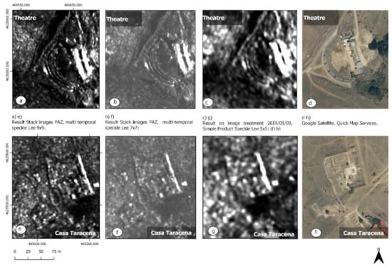
Figure 3.
Comparison of a multi-temporal analysis of SAR-X radar images with individual treatment in the areas of the theatre (a–d), and Casa Taracena/forum (e–h).
2.2. LiDAR Sources: Techniques Used
First of all, we downloaded the *.las files corresponding to our work area from the servers of the National Geographic Institute (IGN). We followed the method described by Massini et al. [16] (pp. 6–7) for the improvement of the DSM, except in the described part of creating the surface (mesh) from the point cloud. The reason was not to be able to have the functions described by the authors for the generation of surfaces, because they are typical of commercial software. For that reason, and to create the DSM with a resolution of 0.38 m/pixel, the triangulation function of SAGA was used, based on the Delaunay triangulation. The error and noise points had been filtered in advance, and then from the resulting point cloud were selected those classified 2 to 6 (base, low vegetation, medium vegetation, high vegetation, and building). Again, to the recommendations of Massini et al. [16] (pp. 10–12) regarding the use of the Lee filter. However, their same recommendations for the Lee filter window size could not be adopted, since the SAGA’s Lee-based multi-direction filter Lee feature does not allow such a selection. However, according to the implementers, this function that looks for the minimum variance in 16 directions preserves the edges and is useful in eliminating the speckle noise of the SAR images or the smoothing of the DTMs, preserving the breaks of slopes and narrow valleys [31].
From here, the various forms of visualization derived from the MDS provided by the RVT program were generated, such as the Sky-View Factor, Openness Positive and Negative, Simple Local Relief Model (SLRM), etc.
The second type of treatment was to work on the values of the IR, R and B bands contained in the information of each of the points of the cloud registered in the LAS files of the PNOA. In the LIDAR flights, carried out by the PNOA from 2009 onwards, a combined flight was applied, allowing to perform simultaneously the capture of the image and the altimetric information. As of 2015, a simultaneous capture with a four-band image (RGB and near infrared) was generalized again, with medium-format cameras. This combined process is described by Lorite et al. [32] as the colour assignment to the point cloud from orthophotographs from the PNOA Image project, or from the flight itself carried out to obtain the LiDAR, in the event that this flight included a photographic camera. To give colour to the point cloud, a process is carried out that consists of assigning to each point of the same the interpolated RGB (Red Green Blue) value of the set of pixels of the ortho-photography corresponding to that areas that are in the same position on the ground. Apart from giving RGB colour, which is what the point cloud is distributed with, internally, false colour (NearInfrared Red Blue) is also assigned to the points, adding the infrared value. Therefore, what we conducted was to use the interpolation functions of SAGA, triangulation, to first generate individual images for each of the bands contained in the points, and then make a combination of them in false colour. With the resulting images, the SAGA function of principal component analysis (PCA) was applied, especially due to the good result obtained by our team when applying them in the published project on the Egyptian landscape of the Oxirrinquita nomos [12] with Worldview 2 images, and in analytics carried out in the Clunia project with SPOT multispectral images [1]. PCA is a multivariate statistical method used to reduce the dimensionality of the data resulting in the reduction of redundant information. In general, the first component explains the maximum proportion of variance of the original dataset [33]. PCA was estimated in the work presented by Aqdus et al. [34], as the most effective visualization tool for multi- and hyperspectral images.
On the other hand, the multispectral image obtained from the LiDAR PNOA point cloud was also applied to vegetation index functions, fifteen in total, provided by the SAGA GIS program. Let us remember that vegetation indices are effective methods to detect and quantify plants through remote sensing [35]. However, the variation in data based on habitat and substrate causes the same index not to work the same in dense forests, pastures, drylands, desert, or humid areas. This has led to the creation of about 150 vegetation indices [36]. With reference to archaeology, these indices are useful for the detection of buried structures since they tend to modify the growth and phenology of the overlying vegetation [37]. Its use in archaeological prospecting has had wide acceptance and good results both from remote sensing using satellite sensors, and currently—from UAVs equipped with multispectral cameras.
2.3. TripleSat Sources
The TripleSat images were treated first by adapting their four NIR bands, R, G, B, at 3.2 m/pixel resolution, to the resolution of the panchromatic, 0.8 m/pixel. The QGIS pansharpening function was used for obtaining a composite image of 4 bands at a resolution of 0.8 m/pixel. Next, we proceeded to work with the multispectral image applying the statistical function of the SAGA principal components analysis, and the aforementioned vegetation indices provided by the SAGA GIS were applied.
3. Results
3.1. Areas Explored in the Results
We observed the results of all the analyses carried out focusing on four areas of the Clunia deposit (Figure 4). Two of them are within the limits of the site (forum and theatre/forum/Cuevas Ciegas area), another corresponds to the borders of the site and one of the supposed lines out of the city (Cuevas Ciegas), and finally a fourth, not excavated, located outside the city walls south of the city and corresponding to a funerary route (Rodeles II).
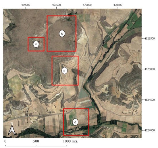
Figure 4.
Areas explored with the results of analyzing the SAR images of PAZ. (a) Clunia forum. (b) Forum–theatre–Cuevas Ciegas area. (c) Cuevas Ciegas. (d) Rodeles II. Source: Google satellite QuickMapServices.
There were various motivations for choosing each of the zones. In the first case, the forum area (Figure 4a), the reason was the observation of various anomalies in the PNOA images, also identified in the PAZ image. Surprising anomalies, given that in principle the space where they appear is the forum square, a space that would have to be free of structures, unless there had been a previous and/or later occupation of the public space.
In the second case, the theatre/forum/Cuevas Ciegas area (Figure 4b), we wanted to review the explorations carried out in the article published in 2019. Explorations which, as mentioned, made it possible to determine a new urban orientation that was added to those previously known and connected with the monumental spaces of the forum, Casa Taracena, the theatre, or the Termas de los Arcos. In addition, any information that could be added to the data of a large area not yet excavated would be of great interest.
The third, Cuevas Ciegas (Figure 4c), had also been the result of a study [1,38,39,40] both in terms of the access roads to the city from the plane, and in determining the main networks drainage of city waters towards the plane.
Finally, the fourth exploration zone, Rodeles II (Figure 4d), was chosen as an element to assess the capacity of contrasting radar images with quite optimal results for the use of multispectral images in the detection of anomalies in the landscape.
3.2. The Area of the Forum
In the highest resolution RGB images (Figure 5a), no significant changes are appreciated except for a dark area located NE of the forum plaza, a short distance from the line of the forum portico. It is difficult to see a line with a NE–SW direction, and a transversal with a NW–SE direction. On the other hand, is the contrast with the image of the 1956 flight (Figure 5b), in which the separation limits of properties with the NE–SW direction, and the delimiting wall of the hermitage with the NW–SE direction can be seen first. In this case, a first reasoning may suggest that the traces seen in the first image are actually remnants of the parcel separation. However, in the photograph of the American flight 1957, there can also be seen two darker zones regarding the rest in the same area, a central area of the square, and another on its NE side.
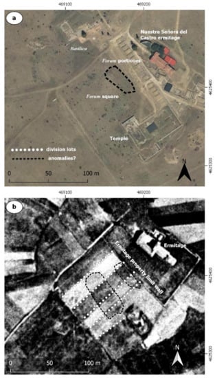
Figure 5.
(a) Google satellite QuickMapServices. (b) USAF flight 1957.
The possibility of encountering an abnormality in this area increases when we go on to analyse the IRGB images of the PNOA flights in 2007, and the IRGB image obtained from LiDAR in 2010. In the first case (Figure 6), we clearly evaluate the lines corresponding to the land division and the separation wall of the hermitage (aligned black and white triangles), but also observed in the area’s centre in front of the temple, and the lateral NE of the forum (ellipses dashed line in black) increases in a hue of red due to vegetation growth. In the second, the IR R B image (Figure 7a) allows to see, in the central part, the reverse situation in two areas (polygon with a blank dashed line). This indicates a slower growth of vegetation and a lack of humus area most to this increase, creating two areas in the centre. The PCA analysis (Figure 7b), indicates that those construction elements (buildings, roads, etc.) present a red hue, which is repeated in the two areas mentioned above. It should be noted that, in this case, both images are apparently present on the W side of the square, shown as an arrangement of perpendicular lines.
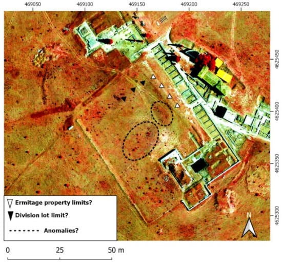
Figure 6.
PNOA 2009, 25 cm. Bands NIRGB.
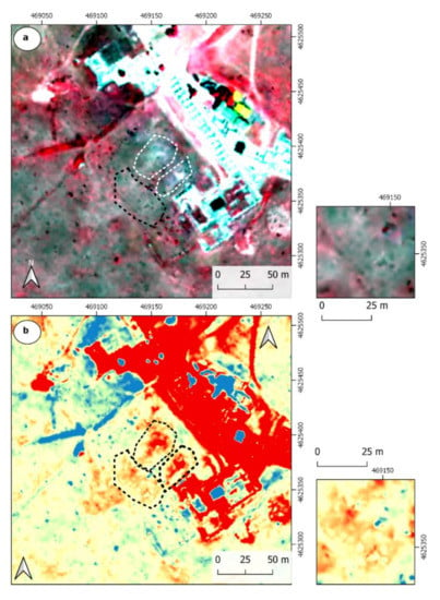
Figure 7.
(a) LiDAR IR R G image; (b) Image result of the first component obtained from a principal component analysis (PCA) applied to the LIDAR IRGB image. Note in the latter how the red color, associated with altered areas, is observed in the central plaza of the forum and on the NE/SW side.
The analysis of the 2016 TripleSat image (Figure 8a) shows another abnormality in the area in front of the NE side of the porch of the forum (ellipse dotted line in black). In this case, apparently, it gives rise to two quadrangular delimited spaces. The NE–SW alignments do not coincide with the crop parcel subdivisions from the 1956 flight. The PCA analysis of the multispectral image shows a similar result in the first component (Figure 8b).
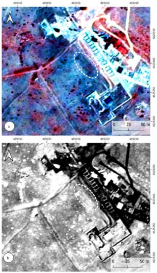
Figure 8.
(a) TripleSat image from 18 June 2016, bands IR, R, G; (b) First component analysis principal component applied to image TripleSat of 18 June 2016.
Finally, when we go on to analyze the results of the X-SAR images (Figure 9) of the PAZ satellite, we find in the central area, in front of the temple, an anomaly with white tones. This anomaly presents alignments with the NW–SE and NE–SW directions creating apparent bounded spaces. When we are on the ground, it is not possible to detect revealing details, such as micro reliefs, that may be associated with the presence of construction elements, coinciding in principle with what is expected for what would be the forum square. Perhaps some detail, such as the one indicated in Figure 10, can be appreciated, but nothing that could suggest that we are on structures or the presence of micro reliefs.
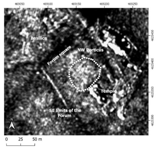
Figure 9.
Image resulting from the multi-temporal application of the co-register function with five SAR-X images of PAZ.
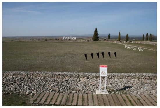
Figure 10.
View of the forum from the temple. Arrows in black indicate an apparent alignment in front of the temple.
We wanted to perform a deeper analysis of the X-SAR image. To do this, we proceeded to draw eight lines with a NE–SW orientation with the intention of obtaining the intensity reading profiles (Figure 11). The SNAP program allows the creation of these profiles from the tracing of polylines on the image. Observation of the graphs of profiles applied to the obtained X-SAR image shows a first peak, or followed by a concavity we have identified as the border of the portico of the forum and the drainpipe. From here, we can find that the peaks of the curves tend to occur successively in the same position of each of the samples taken. This could be indicating the presence of longitudinal intrusive elements (vertical lines in Figure 11). On the other hand, in some of the profiles we evaluated the presence of profiles, in which the peak is maintained for several meters with few alterations (horizontal lines in Figure 11), indicating that we may be facing intrusive longitudinal elements, coinciding approximately with the orientation of the profile line. Therefore, apparently, it seems that the radar is detecting possible construction elements.
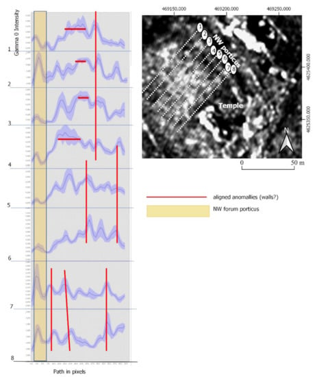
Figure 11.
Profiles of eight samples taken from the multi-temporal SAR-X PAZ radar image. The red lines are indicating a repetition rate of reading the signal, and, therefore, the presence of aligned elements.
3.3. The Theatre/Forum/Cuevas Ciegas Area
As mentioned, it was in this area where our team [1] had determined the presence of traces of urban organization with a N/S orientation, in this case applying other techniques and digital sources, such as SPOT-5 images. In this case, we have contrasted results of the radar image (Figure 12b) with the application of the SLRM function (Figure 12c) to the DTM obtained from the LiDAR point cloud. The use of the second type technique produces better results than in the first case. These can be seen in Figure 12a.
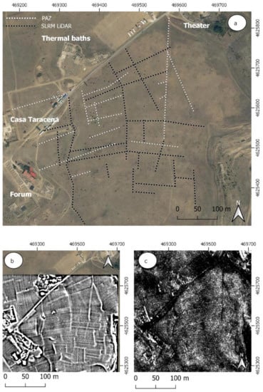
Figure 12.
(a) Google satellite QuickMapServices; (b) Result of the simple local relief model (SLRM) function on the DSM obtained from LiDAR PNOA; (c) Image resulting from the multi-temporal application of the co-register function with five SAR-X images of PAZ.
It is necessary to take into consideration the profound modern high celling division, observed on the American flight 1956, and which is barely visible today. This greatly conditions and distorts the results in trace detection. It is true that the plot division and subdivision itself may be in result of a morphological evolution of the urban organization of Clunia. However, the period of abandonment, sedimentation, agricultural work, and pillaging material from its abandonment, in turn may have masked elements as some of the traces that, if detected in the radar image, have a similar orientation as that of Casa Taracena, and they do not appear in the image of the 1956 flight, nor in the results of applying the SLR function to the DEM obtained by LiDAR.
3.4. The Cuevas Ciegas Area
In this case, the observation of the treated image of PAZ (Figure 13c) has provided the identification of two anomalies associated, on the one hand, with one of Clunia’s waste water systems (Figure 13a), identified in previous works [1] through the application of GIS functions for the creation of a water network from the DEM. This anomaly is not observed in the rest of the multispectral images IR R B Lidar, PNOA, or TripleSat, except for the PNOA IRGB image of 2009, and it is only seen in the 1956 flight. This anomaly is not observed directly on the ground in some change of vegetation (Figure 14).
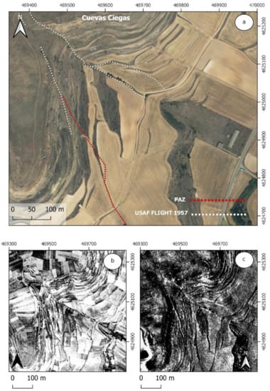
Figure 13.
(a) Google satellite QuickMapServices; (b) USAF flight 1957; (c) Image resulting from the multi-temporal application of the co-register function with five SAR-X images of PAZ.
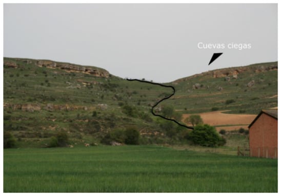
Figure 14.
Detailed photo with a black-line indication of the scrapping channel.
The second anomaly that can be displayed in the image PAZ course corresponds to the section of one of the paths to Clunia studied by Camacho [39,40,41] and that also is only observable in flight USAF 1957 (Figure 13b).
3.5. The Burial Area, Los Rodeles II
Around the Alto de Castro, there are three large funerary spaces distributed from south to east, between the middle area of the hillside and the plain of the Arandilla River. The most obvious sample can be found on a terrace at the foot of the Cuevas Ciegas access point, in the site called Torreón, where the remains of an imposing structure identified as a mausoleum are preserved, surely dedicated to a prominent figure [39] (p.268). It is, therefore, a necropolis on the access road to the city, which is also connected to the presence of other possible funerary monuments at nearby points on the same hillside. In its vicinity is the funeral route located in the fertile plain of Arandilla, registered as Rodeles II. In the latter case, aerial photography made it possible to determine that the site is made up of a series of structures and enclosures associated with a road that crosses the river [41]. There is no doubt that these are funeral precincts, such as those mentioned above, distributed on both sides of the road [40] (pp.267–268), [38] (pp. 220–222).
The observation of the site of Rodeles II (Figure 15) has allowed us to find PNOA images from 2011, in which it was possible to identify the structures almost at the same level of visualization and clarity of the aerial photographs taken in this area. These structures can also be seen in the infrared image of LiDAR of the PNOA flight. To complete the works, we carried out PCA analytics and a calculation of the vegetation indices, among which the Perpendicular Vegetation Index [42] (Figure 15e) has stood out. When compared with the radar image resulting from the multi-temporal treatment, we saw that the media operation has left evidence of the anomaly of the track, but lost the information corresponding to the structures associated with the funeral area. For this reason, we carried out an individual treatment of one of the PAZ images, the one from 29 August 2019, which reveals the presence of the aforementioned structures that perpendicularly cross the funeral via (Figure 15b).
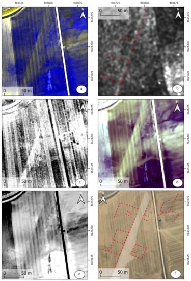
Figure 15.
(a) PNOA 2011 50 cm (Bands B, B, IR); (b) PAZ 29 August; (c) USAF flight 1957; (d) LiDAR PNOA IR RG (Bands R R G); (e) Perpendicular Vegetation Index (Walther and Shabaani); (f) Google satellite QuickMapService..
4. Discussion
According to Stewart et al. [30], remote sensing with SAR has only been fully successful in areas covered by sand. On the other hand, Dore et al. [43] maintained that the characteristics of these types of SAR sensors (independent of the external light source, penetration areas cloud cover, or soil penetration) have extended the limits of acquisitions from optical satellites, and the combined use of both types of sensors in archaeological remote sensing research was advisable. Stewart himself [29] also showed the potential to also use multispectral reflectance and radar in a combined manner, although in this case he delved into the use of interferometric coherence. This combination could help in the detection and interpretation of changes that could affect archaeological sites, such as, for example, illegal excavations.
However, the use of SAR has had results of interest in non-arid and vegetated areas, as is the case in Lazio [29,30] with the detection of archaeological forms, combining results of SAR intensity and interferometry. In both cases, the probability of locating archaeological structures has increased.
According to Monterroso and Martinez [8], it is in spaces of cultivated soils where it seems easier to interpret the SAR-X images compared to bare soils, as Stewart et al. [44] (p. 204, 208) in the Portus de Ostia. In addition, continued Monterroso and Martinez, this interpretation was maintained in cases in which there are periods of intense rain with soils humidity indexes higher than the annual index.
In the current case, the selection of PAZ images was carried out in meteorological contexts in months with significant differences between the maximum and minimum high temperatures, with little rainfall. It should be noted, however, that the best possible picture has display elements such as the zone Rodeles II, precisely performed after one of two rainy pulsations occurred in August 2019 (Table 2, T.Max: 25.07; T.Min: 14; T.Med: 19.9 Prec.: 2.4 mm). Let us also bear in mind that the space where this deposit is located corresponds precisely to cultivated soils, or in cultivation period.

Table 2.
Source data from the AEMET meteorological station of Coruña del Conde (Burgos). (Web source database: https://es.meteosolana.net/estacion/2106B, accessed on 23 April 2021).
On the other hand, we have seen that the application of the co-register function with a stack of temporally spaced images provides more clarifying results than the individual analysis of each of the images, except in one of the areas—the one corresponding to the Rodeles II.
Our analysis of the SAR images confirms one of the first utilities, and it is the possibility of detecting hydraulic or road infrastructures as we had indicated when analysing the area of Cuevas Ciegas or Rodeles II, or also, elements that can help to complete one of the most interesting aspects of the study of Clunia as its urban organization may be. On the other hand, in Rodeles II, we were able to confirm that better results are obtained on cultivated soils since these remains were found in a cultivated area in front of spaces of the site itself that stopped being cultivated at the end of the 20th century.
It remains to be determined whether the anomalies apparently identified in the forum area actually correspond to building structures. It is interesting to have verified that the anomalies were detected by analysing sources of information as varied as radar or multispectral images.
5. Conclusions
Above all, throughout this work, we were able to verify the possibilities of using SAR-X radar images in non-invasive archaeological prospecting. However, we understand up to the time of our research, and as other authors have already indicated, that the use of this technology must be accompanied by other sources in result of remote sensing, such as multispectral optical images or thermal images. In that sense, our future interest lies in adding other analyticals such as polarimetry SAR, as described by Stewart, Lasaponara and Sciavon [45], or to perform flights at low-altitude UAV using thermal and multispectral cameras, combined with geophysical surveys to check the results. Recent works are already developing by us in other archaeological areas. As we mentioned at the beginning of this work, we are experimenting with the PAZ data in other areas with different geographical characteristics, such as the already mentioned Oxirrinco (Egypt) or Cosa (Italy). The same SAR-X image analysis techniques described in the text were applied. However, it is still pending a review and comparison with other sources, such as multispectral images. Our long-term objective is to review and determine in greater detail the physical and seasonal conditions in which SAR-X data can provide the best results in the search for archaeological elements.
We see that the application of a multi-temporal treatment on the radar images helps to enhance the resulting images against individual scenes.
On the other hand, the detection of anomalies in the area of the forum using various non-invasive analysis systems opens up new urban unknowns associated with the moments before and after the construction of the forum that will have to be verified in archaeological interventions.
Author Contributions
Conceptualization, I.F. and R.C.; methodology, I.F.; software, I.F. and P.M.M.; validation I.F., R.C. and E.S.; investigation, I.F., R.C. and E.S.; resources, I.F. and R.C.; data curation, I.F. and P.M.M.; writing—original draft preparation, I.F.; writing—review and editing, I.F. and P.M.M.; supervision, R.C. and E.S.; project administration, I.F. All authors have read and agreed to the published version of the manuscript.
Funding
This research received no external funding.
Institutional Review Board Statement
Not applicable.
Informed Consent Statement
Not applicable.
Acknowledgments
The authors would like to thank the INTA-PAZ Science Team for providing the PAZ data in the framework of the “AO-001-018” project (018 Application of Radar images of the PAZ Satellite in the Detection of Archaeological Remains, ARQPAZ). Also our thanks to the Rovira i Virgili University for granting financial support for this open access publication.
Conflicts of Interest
The authors declare no conflict of interest.
References
- Cuesta, R.; Fiz, I.; Subías, E.; Tuset, F.; Iglesia, M.A. Hydraulic and urban management during Roman times based on GIS and remote sensing analysis (Clunia, Spain). Rev. Arqueol. Ponent 2019, 29, 123–146. [Google Scholar] [CrossRef]
- McCauley, J.F.; Breed, C.S.; Schaber, G.G.; McHugh, W.P.; Issawi, B.; Haynes, C.V.; Grolier, M.J.; Kilani, A.E. Paleodrainages of the Eastern Sahara. The Radar Rivers revisited. IEE Trans. Geosci. Remote Sens 1986, 24, 624–647. [Google Scholar]
- McCauley, J.F.; Schaber, G.G.; Breed, C.S.; Grolier, M.J.; Haynes, C.; Issawi, B.; Elachi, C.; Blom, R. Subsurface Valleys and Geoarchaeology of the Eastern Sahara Revealed by Shuttle Radar. Science 1982, 218, 1004–1020. [Google Scholar] [CrossRef]
- Blom, R.; Crippen, R.; Elachi, C.; Zarins, J.; Clapp, N.; Ledges, G. Space Technology and the discovery of the lost city of Ubar. In Proceedings of the IEEE Conference: Aerospace Conference, Snowmass, CO, USA, 13 February 1997; Volume 1. [Google Scholar]
- Adams, R. Swamps, Canals and the Locations of Ancient Maya Cities. Antiquity 1980, 54, 206–214. [Google Scholar] [CrossRef]
- Sever, T.L.; Irwin, D.E. Remote sensing investigation of the Ancient Maya in the Peten Rainforest of Northern Guatemala. Anc. Mesoam. 2003, 14, 113–122. [Google Scholar] [CrossRef]
- Lasaponara, R.; Massini, N. Satellite Synthetic Aperture Radar in Archaeology and Cultural Landscape: An Overview. Archaeol. Prospect. 2013, 20, 71–78. [Google Scholar] [CrossRef]
- Monterroso, A.; Martinez, T. COSMO SkyMed X-Band SAR application—Combined with thermal and RGB images—in the archaeological landscape of Roman Mellaria (Fuente Obejuna-Córdoba, Spain). Archaeol. Prospect. 2018, 25, 301–314. [Google Scholar] [CrossRef]
- Hisdesat, PAZ Image Product Guide, PAZ-HDS-GUI-001. 2019. Available online: https://www.hisdesat.es/wp-content/uploads/2019/10/PAZ-HDS-GUI-001-PAZ-Image-Product-Guide-issue-1.1-.pdf (accessed on 1 April 2021).
- Cerra, D.; Agapiou, A.; Cavalli, R.M.; Sarris, A. An Objective Assessment of Hyperspectral Indicators for the Detection of Buried Archaeological Relics. Remote. Sens. 2018, 10, 500. [Google Scholar] [CrossRef]
- Pydyn, A.; Popek, M.; Kubacka, M.; Janowski, L. Exploration and reconstruction of a medieval harbour using hydroacoustics, 3-D shallow seismic and underwater photogrammetry: A case study from Puck, southern Baltic Sea. Archaeol. Prospect. 2021, 28, 527–542. [Google Scholar]
- Subias, E.; Fiz, I.; Cuesta, R. The Middle Nile Valley: Elements in an approach to the structuring of the landscape from the Greco-Roman era to the nineteenth century. Quat. Int. 2013, 312, 27–44. [Google Scholar] [CrossRef]
- Roca, M.; Fiz, I. Reconstrucción, a partir de fotografía aérea, de la topografía de la colonia de Cosa (Ansedonia, Italia) in Roca. In Proyecto Cosa: Intervenciones Arqueológicas de la Universidad de Barcelona en la Ciudad Romana; Madrid, M., Celis, R., Eds.; Universidad de Barcelona: Barcelona, Spain, 2013; pp. 69–89. Available online: http://diposit.ub.edu/dspace/bitstream/2445/99120/6/Proyecto_Cosa_optimitzat.pdf (accessed on 1 April 2021).
- Wen, Q.; Hea, J.; Guana, S.; Chena, T.; Hua, Y.; Wua, W.; Liua, F.; Qiaoa, Y.; Kokb, S.; Yeong, S. The TripleSat constellation: A new geospatial data service model. Geo. Spat. Inf. Sci. 2017, 20. [Google Scholar] [CrossRef]
- Kokalj, Z.; Hesse, R. Airborne Laser Scanning Raster Data Visualization: A Guide to Good Practice; Založba ZRC: Ljubljana, Slovakia, 2017. [Google Scholar]
- Masini, N.; Gizzi, F.T.; Biscione, M.; Fundone, V.; Sedile, M.; Sileo, M.; Pecci, A.; Lacovara, B.; Lasaponara, R. Medieval Archaeology under the Canopy with LiDAR. The (Re)Discovery of a Medieval Fortified Settlement in Southern Italy. Remote Sens. 2018, 10, 1598. [Google Scholar] [CrossRef]
- Garcia Sanchez, J. Archaeological LiDAR in Italy: Enhancing research with publicly accessible data. Antiquity 2018, 92, 1–10. [Google Scholar]
- Roman, A.; Ursu, T.; Lăzărescu, V.; Opreanu, C.H. Multi-sensor surveys for the interdisciplinary landscape analysis and archaeological feature detection at Porolissum in Coriolan. In Landscape Archaeology on the Northern Frontier of the Roman Empire at Porolissum an Interdisciplinary Research Project; Opreanu, H., Lăzărescu, V.A., Eds.; Mega Publishing House: Cluj-Napoca, Romania, 2016; pp. 237–262. [Google Scholar]
- Meyer, F. Spaceborne Synthetic Aperture Radar: Principles, Data Access, and Basic Processing Techniques in Ixmucane. In The Synthetic Aperture Radar (SAR) Handbook: Comprehensive Methodologies for Forest Monitoring and Biomass Estimation; Flores-Anderson., A.E., Herndon., K., Bahadur Thapa, R., Cherrington., E., Eds.; SERVIR Global Science Coordination Office: Huntsville, AL, USA, 2019. [Google Scholar]
- Bruniquel, J.; Lopes, A. Multi-variate optimal speckle reduction in SAR imagery. Int. J. Remote Sens. 1997, 18, 603–606. [Google Scholar] [CrossRef]
- Ferretti, A.; Fumagalli, A.; Novali, F.; Prati, C.; Rocca, F.; Rucci, A. A New Algorithm for Processing Interferometric Data-Stacks: SqueeSAR. IEEE Trans. Geosci. Remote Sens. 2011, 49, 3460–3470. [Google Scholar] [CrossRef]
- Huang, S.-Q.; Liu, D.-Z.; Gao, G.-Q.; Guo, X.-J. A novel method for speckle noise reduction and ship target detection in SAR images. Pattern Recognit. 2009, 42, 1533–1542. [Google Scholar] [CrossRef]
- Lee, J.-S.; Grunes, M.; Mango, S. Speckle reduction in multipolarization, multifrequency SAR imagery. IEEE Trans. Geosci. Remote Sens. 1991, 29, 535–544. [Google Scholar] [CrossRef]
- Lee, J.-S.; Jurkevich, L.; Dewaele, P.; Wambacq, P.; Oosterlinck. A.Speckle fltering of synthetic aperture radar images: A review. Remote Sens. Rev. 1994, 8, 313–340. [Google Scholar] [CrossRef]
- Lopez-Martinez, C.; Pottier, E. On the Extension of Multidimensional Speckle Noise Model from Single-look to Multilook SAR Imagery. IEEE Trans. Geosci. Remote Sens. 2007, 45, 305–320. [Google Scholar] [CrossRef]
- Novak, L.M.; Burl, M.C. Optimal speckle reduction in polarimetric SAR imagery: Aerospace and Electronic Systems. IEEE Trans. Geosci. Remote Sens. 1990, 26, 293–305. [Google Scholar]
- Sveinsson, J.R.; Benediktsson, J.A. Almost translation invariant wavelet transformations for speckle reduction of SAR images. IEEE Trans. Geosci. Remote Sens. 2003, 41, 2404–2408. [Google Scholar] [CrossRef]
- Tapete, D.; Cigna, F. COSMO-SkyMed SAR for Detection and Monitoring of Archaeological and Cultural Heritage Sites. Remote Sens. 2019, 11, 1326. [Google Scholar] [CrossRef]
- Stewart, C. Detection of Archaeological Residues in Vegetated Areas Using Satellite Synthetic Aperture Radar. Remote Sens. 2017, 9, 118. [Google Scholar] [CrossRef]
- Stewart, C.; Oren, E.; Cohen-Sasson, E. Satellite Remote Sensing Analysis of the Qasrawet Archaeological Site in North Sinai. Remote Sens. 2018, 10, 1090. [Google Scholar] [CrossRef]
- Selige, T.; Böhner, J.; Ringeler, A. Processing of SRTM X- SAR data to correct interferometric elevation models for land surface process applications. Göttinger Geogr. Abh. 2006, 115, 97–104. [Google Scholar]
- Lorite, S.; Ojeda, J.C.; Rodríguez-Cuenca, B.; González Cristóbal, E.; Muñoz, P. Procesado y distribución de nubes de puntos en el proyecto PNOA-LiDAR. In Nuevas Plataformas y Sensores de Teledetección, Proceedings of the Actas del XVII Congreso de la Asociación Española de Teledetección, Murcia, Spain, 3–7 October 2017; Ruiz, L.A., Estornell, J., Erena, M., Eds.; Universidad de Valencia: Valencia, Spania, 2017; pp. 329–332. Available online: https://n9.cl/2y9yf (accessed on 14 June 2021).
- Zhao, G.; Maclean, A.L. A comparison of canonical discriminant analysis and principal component analysis for spectral transformation. Photogramm. Eng. Remote Sens. 2020, 66, 841–847. [Google Scholar]
- Aqdus, S.; Hanson, W.B.; Drummond, J. The potential of hyperspectral and multi-spectral imagery to enhance archaeological cropmark detection: A comparative study. J. Archaeol. Sci. 2012, 39, 1915–1924. [Google Scholar] [CrossRef]
- Eastman, J.R. IDRISI for Windows: Guide to GIS and Image Processing Version 32.20, 2001; Clark University: Worcester, MA, USA, 2001; Volume 2. [Google Scholar]
- Verrelst, J.; Koetz, B.; Kneubühler, M.; Schaepman, M. Directional sensitivity analysis of vegetation indices from multiangular CHRIS/PROBA data. In Proceedings of the ISPRS Commission VII Mid-term Symposium Remote Sensing: From Pixels to Processes, Enschede, The Netherlands, 8–11 May 2006. [Google Scholar]
- Lasaponara, R.; Masini, N.; Scardozzi, G. Immagini satellitari ad alta risoluzione e ricerca archeologica: Applicazioni e casi di studio con riprese pancromatiche e multispettrali di Quickbird. Archeol. Calc. 2007, 18, 187–227. [Google Scholar]
- Camacho, G. El territorio de Clunia y su evolución entre los siglos I a. C. y X d. C.: Perspectivas arqueológica e histórica. Tesis Doctoral, Universidad de Barcelona, Barcelona, Spain. Available online: https://www.tdx.cat/bitstream/handle/10803/666964/GCV_TESIS.pdf?sequence=1 (accessed on 1 April 2021).
- Camacho, G. Clunia: Una perspectiva arqueológica. CLIO. Hist. Hist. Teach. 2014, 40, 17–42. [Google Scholar]
- Camacho, G. Aproximación descriptiva a las vías y accesos de la Colonia Clunia Sulpicia (Peñalba de Castro-Burgos). Hisp. Antiqva 2013, 37, 249–270. Available online: https://dialnet.unirioja.es/descarga/articulo/5075608.pdf (accessed on 1 April 2021).
- Del Olmo, J. Arqueología aérea en Clunia. Rev. de Arqueol. 2001, 244, 6–9. [Google Scholar]
- Walther, D.; Shabaani, S. Large scale monitoring of rangelands vegetation using NOAA/AVHRR LAC data: Application to the rainy seasons 1989/90 in northern Kenya. In Range Management Handbook of Kenya; Ministry of Livestock Development: Nairobi, Kenya, 1991. [Google Scholar]
- Dore, N.; Patruno, J.; Pottier., E.; Crespi, M. New Research in Polarimetric SAR Technique for Archaeological Purposes using ALOS PALSAR Data. Archaeol. Prospect. 2013, 20, 79–87. [Google Scholar] [CrossRef]
- Stewart, C.; di Iorio, A.; Schiavon, G. Analysis of the utility of Cosmo Skymed strip map to detect buried archaeological features in the region of Rome. Experimental component of WHERE project. In Towards Horizon 2020: Earth Observation and Social Perspectives, Proceedings of the 33rd EARSeL Symposium Matera, Italy, 3–6 June 2013; Lasaponara, R., Masini, N., Biscione, M., Eds.; European Association of Remote Sensing Laboratories (EARSeL): Matera, Italy; pp. 203–212.
- Stewart, C.; Lasaponara., R.; Schiavon., G. Multi-frequency, polarimetric SAR analysis for archaeological prospection. Int. J. Appl. Earth Obs. Geoinf. 2014, 28, 211–219. [Google Scholar] [CrossRef]
Publisher’s Note: MDPI stays neutral with regard to jurisdictional claims in published maps and institutional affiliations. |
© 2021 by the authors. Licensee MDPI, Basel, Switzerland. This article is an open access article distributed under the terms and conditions of the Creative Commons Attribution (CC BY) license (https://creativecommons.org/licenses/by/4.0/).