Insect Monitoring Radar: Maximizing Performance and Utility


Abstract
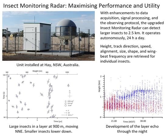
1. Introduction
2. Materials and Methods
2.1. System and Protocol Upgrades
2.1.1. “24/7” Observing and Data Storage
2.1.2. Observing to 2.5 km
2.1.3. Scan Speed and Direction
2.1.4. Elimination of Stationary-Beam Observations
2.1.5. Self-Test and Auto-Recovery
2.2. Signal Acquisition and Preprocessing
2.2.1. Fast Data Acquisition
2.2.2. Video Amplifier
2.2.3. Elimination of Fixed Gates
2.2.4. Preprocessing Algorithm.
3. Results
4. Discussion
5. Conclusions
Supplementary Materials
Author Contributions
Funding
Acknowledgments
Conflicts of Interest
Disclaimer
Appendix A
Problems Arising with Fixed Gates

Appendix B
Preprocessing Procedure


References
- Beerwinkle, K.R.; Witz, J.A.; Schleider, P.G. An automated, vertical looking, X-band radar system for continuously monitoring aerial insect activity. Trans. Am. Soc. Agric. Eng. 1993, 36, 965–970. [Google Scholar] [CrossRef]
- Drake, V.A. Insect-monitoring radar: A new source of information for migration research and operational pest forecasting. In Pest Control and Sustainable Agriculture; Corey, S.A., Dall, D.J., Milne, W.M., Eds.; CSIRO Publications: Melbourne, Australia, 1993; pp. 452–455. [Google Scholar]
- Chapman, J.W.; Reynolds, D.R.; Smith, A.D. Vertical-Looking Radar: A new tool for monitoring high-altitude insect migration. BioScience 2003, 53, 503–511. [Google Scholar] [CrossRef]
- Chapman, J.W.; Nesbit, R.L.; Burgin, L.E.; Reynolds, D.R.; Smith, A.D.; Middleton, D.R.; Hill, J.K. Flight orientation behaviors promote optimal migration trajectories in high-flying insects. Science 2010, 327, 682–685. [Google Scholar] [CrossRef] [PubMed]
- Hu, G.; Lim, K.S.; Horvitz, N.; Clark, S.J.; Reynolds, D.R.; Sapir, N.; Chapman, J.W. Mass seasonal bioflows of high-flying seasonal migrants. Science 2016, 354, 1584–1587. [Google Scholar] [CrossRef] [PubMed]
- Drake, V.A.; Wang, H. Recognition and characterization of migratory movements of Australian Plague Locusts, Chortoicetes terminifera, with an Insect Monitoring Radar. J. Appl. Remote Sens. 2013, 7, 075095. [Google Scholar] [CrossRef]
- Westbrook, J.K.; Eyster, R.S. Doppler weather radar detects emigratory flights of noctuids during a major pest outbreak. Remote Sens. Appl. Soc. Environ. 2017, 8, 64–70. [Google Scholar] [CrossRef]
- Drake, V.A. Distinguishing target classes in observations from vertically pointing entomological radars. Int. J. Remote Sens. 2016, 37, 3811–3835. [Google Scholar] [CrossRef]
- Hao, Z.; Drake, V.A.; Taylor, J.R. Insect target classes discerned from entomological radar data. Remote Sens. submitted.
- Hao, Z.; Drake, V.A.; Taylor, J.R. Resolving the heading-direction ambiguity in vertical-beam radar observations of migrating insects. Ecol. Evol. 2019, 9, 6003–6013. [Google Scholar] [CrossRef] [PubMed]
- Drake, V.A.; Gregg, P.C.; Harman, I.T.; Wang, H.K.; Deveson, E.D.; Hunter, D.M.; Rochester, W.A. Characterizing insect migration systems in inland Australia with novel and traditional methodologies. In Insect Movement: Mechanisms and Consequences; Woiwod, I., Reynolds, D.R., Eds.; CABI Publishing: Wallingford, UK, 2001; pp. 207–233. [Google Scholar] [CrossRef]
- Drake, V.A.; Reynolds, D.R. Radar Entomology: Observing Insect Flight and Migration; CABI: Wallingford, UK, 2012. [Google Scholar]
- Harman, I.T.; Drake, V.A. Insect Monitoring Radar: Analytical time-domain algorithm for retrieving trajectory and target parameters. Comput. Electron. Agric. 2004, 43, 23–41. [Google Scholar] [CrossRef]
- Hu, C.; Li, W.; Wang, R.; Long, T.; Drake, V.A. Discrimination of parallel and perpendicular insects based on relative phase of scattering matrix eigenvalues. IEEE Trans. Geosci. Remote Sens. 2020. [Google Scholar] [CrossRef]
- Drake, V.A. Estimation of unbiased insect densities and density profiles with vertically pointing entomological radars. Int. J. Remote Sens. 2014, 35, 4630–4654. [Google Scholar] [CrossRef]
- Reynolds, A.M.; Reynolds, D.R.; Smith, A.D.; Chapman, J.W. A single wind-mediated mechanism explains high-altitude ‘non-goal oriented’ headings and layering of nocturnally migrating insects. Proc. R. Soc. B Biol. Sci. 2010, 277, 765–772. [Google Scholar] [CrossRef] [PubMed]
- Drake, V.A.; Harman, I.T.; Wang, H.K. Insect Monitoring Radar: Stationary-beam operating mode. Comput. Electron. Agric. 2002, 35, 111–137. [Google Scholar] [CrossRef]
- Wang, H.K.; Drake, V.A. Insect Monitoring Radar: Retrieval of wingbeat information from conical-scan observation data. Comput. Electron. Agric. 2004, 43, 209–222. [Google Scholar] [CrossRef]
- Drake, V.A.; Wang, H.K.; Harman, I.T. Insect Monitoring Radar: Remote and network operation. Comput. Electron. Agric. 2002, 35, 77–94. [Google Scholar] [CrossRef]
- Drake, V.A.; Wang, H. Ascent and descent rates of high-flying insect migrants determined with a non-coherent vertical beam entomological radar. Int. J. Remote Sens. 2019, 40, 883–904. [Google Scholar] [CrossRef]
- Riley, J.R. A radar technique for automatically monitoring insect migration and bio-diversity. In Biotelemetry XII, Proceedings of the Twelfth International Symposium on Biotelemetry, Ancona, Italy, 31 August–5 September 1992; Mancini, P., Fioretti, S., Cristalli, C., Bedini, R., Eds.; Editrice Universitaria Litografia Felici: Pisa, Italy, 1993; pp. 310–317. [Google Scholar]
- Song, Z.; Zhang, B.; Feng, H.; Zhu, S.; Hu, L.; Brydegaard, M.; Li, Y.; Jansson, S.; Malmqvist, E.; Svanberg, K.; et al. Application of lidar remote sensing of insects in agricultural entomology on the Chinese scene. J. Appl. Entomol. 2019. [Google Scholar] [CrossRef]


| Subsystem, Operation. | Parameters, Features. |
|---|---|
| Frequency/wavelength Transmitter Receiver | 9.4 GHz/3.2 cm (X-band). Pulsed, 25 kW peak power (nominal), repetition frequency 960 Hz, pulse duration 0.05 μs (‘S-mode’), 0.25 μs (‘M-mode’). Non-coherent, logarithmic amplification; bandwidth ~20 MHz, minimum detectable signal −90 dBm. |
| Antenna Beam Scan Polarization | Parabolic reflector, diameter 1.8 m, directed vertically; gain 43 dB; losses (radome, waveguide) ~3 dB (two way). Circular pencil beam (full width at half maximum 1.1°), Gaussian intensity pattern. Narrow-angle conical, offset 0.24 beam-widths. 450 r.p.m. (7.5 Hz, period 0.133 s, alternating clockwise and anticlockwise at hourly intervals). Linear, turning synchronously with conical scan a; E-field aligned with offset direction. |
| Sampling (fast time) Sampling (slow time) Observing protocol | Video transformed into −5 to +5-V range and sampled at 60 or 120 MHz b over 0–9 μs (S-mode, 0–1350 m in range) or 8–17 μs (M-mode, 1200–2550 m); 540 or 1080 samples per pulse. 960 Hz (128 fast-time sequences per scan cycle). 15-min cycle comprising 3 S-mode and 1 M-mode observing periods, each of 3-min duration. |
| Operation | Continuous (“24/7”), fully automatic, with self-testing (multiple features) and autonomous recovery. |
© 2020 by the authors. Licensee MDPI, Basel, Switzerland. This article is an open access article distributed under the terms and conditions of the Creative Commons Attribution (CC BY) license (http://creativecommons.org/licenses/by/4.0/).
Share and Cite
Drake, V.A.; Hatty, S.; Symons, C.; Wang, H. Insect Monitoring Radar: Maximizing Performance and Utility. Remote Sens. 2020, 12, 596. https://doi.org/10.3390/rs12040596
Drake VA, Hatty S, Symons C, Wang H. Insect Monitoring Radar: Maximizing Performance and Utility. Remote Sensing. 2020; 12(4):596. https://doi.org/10.3390/rs12040596
Chicago/Turabian StyleDrake, V. Alistair, Shane Hatty, Colin Symons, and Haikou Wang. 2020. "Insect Monitoring Radar: Maximizing Performance and Utility" Remote Sensing 12, no. 4: 596. https://doi.org/10.3390/rs12040596
APA StyleDrake, V. A., Hatty, S., Symons, C., & Wang, H. (2020). Insect Monitoring Radar: Maximizing Performance and Utility. Remote Sensing, 12(4), 596. https://doi.org/10.3390/rs12040596