Article

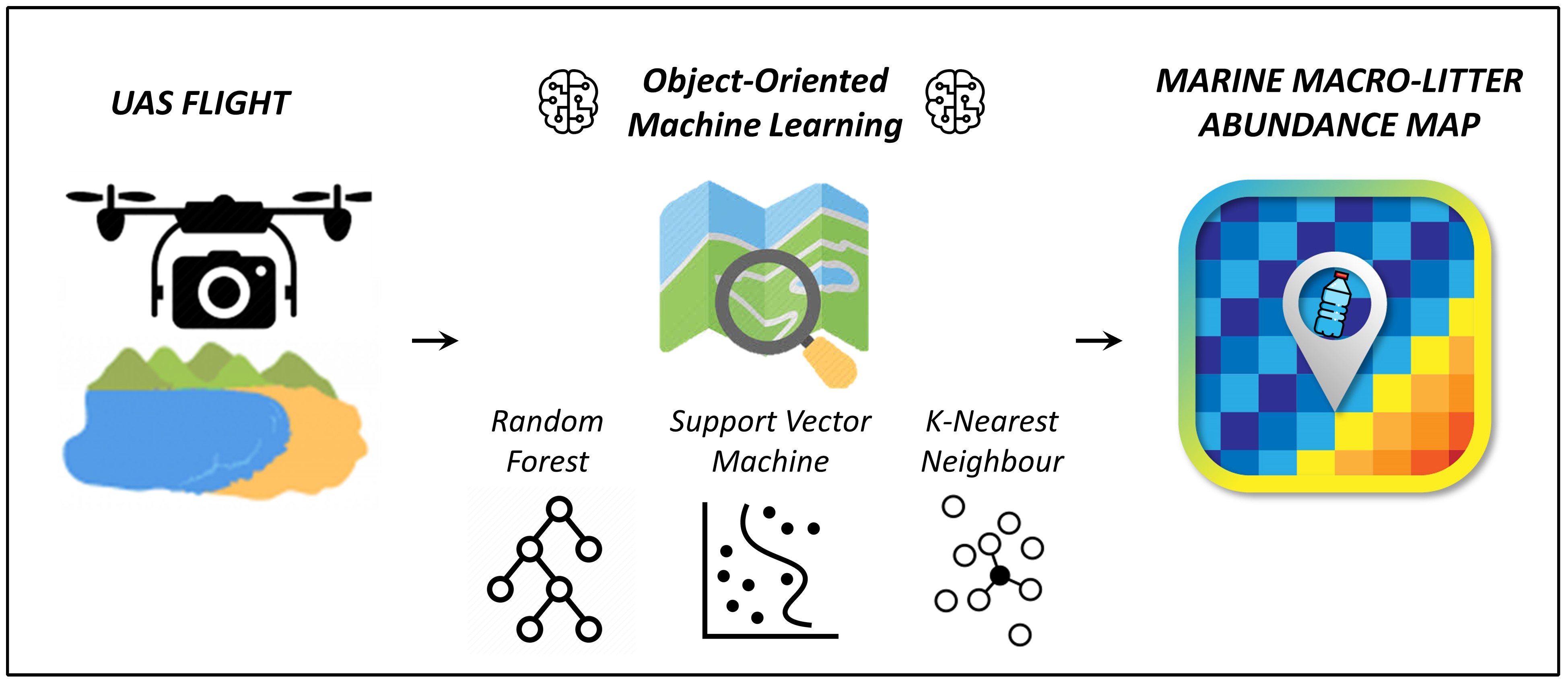
Quantifying Marine Macro Litter Abundance on a Sandy Beach Using Unmanned Aerial Systems and Object-Oriented Machine Learning Methods

1
Department of Mathematics, University of Coimbra, 3001-501 Coimbra, Portugal
2
INESC-Coimbra, Department of Electrical and Computer Engineering, 3030-290 Coimbra, Portugal
3
Polytechnic Institute of Leiria, ESTG, Campus 2–Morro do Lena–Alto Vieiro, 2411–901 Leiria, Portugal
4
MARE-Marine and Environmental Sciences Centre, Faculdade de Ciências e Tecnologia, Universidade NOVA de Lisboa, Campus da Caparica, 2829-516 Caparica, Portugal
5
MARE-Marine and Environmental Sciences Centre, Department of Life Sciences, University of Coimbra, 3000-456 Coimbra, Portugal
*
Author to whom correspondence should be addressed.
Remote Sens. 2020, 12(16), 2599; https://doi.org/10.3390/rs12162599
Submission received: 16 July 2020 / Revised: 9 August 2020 / Accepted: 10 August 2020 / Published: 12 August 2020
(This article belongs to the Special Issue Remote Sensing for Mapping and Monitoring Anthropogenic Debris)

Abstract

:
Unmanned aerial systems (UASs) have recently been proven to be valuable remote sensing tools for detecting marine macro litter (MML), with the potential of supporting pollution monitoring programs on coasts. Very low altitude images, acquired with a low-cost RGB camera onboard a UAS on a sandy beach, were used to characterize the abundance of stranded macro litter. We developed an object-oriented classification strategy for automatically identifying the marine macro litter items on a UAS-based orthomosaic. A comparison is presented among three automated object-oriented machine learning (OOML) techniques, namely random forest (RF), support vector machine (SVM), and k-nearest neighbor (KNN). Overall, the detection was satisfactory for the three techniques, with mean F-scores of 65% for KNN, 68% for SVM, and 72% for RF. A comparison with manual detection showed that the RF technique was the most accurate OOML macro litter detector, as it returned the best overall detection quality (F-score) with the lowest number of false positives. Because the number of tuning parameters varied among the three automated machine learning techniques and considering that the three generated abundance maps correlated similarly with the abundance map produced manually, the simplest KNN classifier was preferred to the more complex RF. This work contributes to advances in remote sensing marine litter surveys on coasts, optimizing the automated detection on UAS-derived orthomosaics. MML abundance maps, produced by UAS surveys, assist coastal managers and authorities through environmental pollution monitoring programs. In addition, they contribute to search and evaluation of the mitigation measures and improve clean-up operations on coastal environments.

Graphical Abstract

1. Introduction

The amount of anthropogenic debris in marine and coastal environments is increasing dramatically and constitutes a global issue. Monitoring the abundance and characterization of anthropogenic marine debris (or marine litter) becomes essential to identify the main sources [1,2] and to design effective mitigation measures [3,4]. In particular, as marine litter is present in large quantities on coastlines [5,6,7], action plans have been implemented to map the load and type of marine litter on beaches worldwide [8,9,10,11,12,13,14,15,16,17].
The most common technique for marine litter monitoring relies on an in-situ visual census approach. This technique, performed generally four times per year, consists of counting, classifying, and recollecting the marine litter items, within the same chosen area [18,19,20]. Although these surveys can be achieved at low cost, with minimal equipment by inexperienced surveyors under instruction [19], the in-situ visual census method requires intensive human effort [7,21].
To overcome the limitations of visual census, recent works have explored the viability of an unmanned aerial system (UAS)-based approach for the detection, identification, and classification of marine litter in coastal areas [22,23,24,25,26,27,28,29]. In these works, the drone flew at a variable height between 6 and 40 m, with the camera gimbal at −90°, and collected high resolution images of the beach surface. In general, the obtained final resolution, expressed usually in terms of ground sampling distance (GSD), allowed one to properly identify the marine macro litter (hereinafter MML), which was defined as any persistent anthropogenic solid material disposed or abandoned in marine and coastal environments, with its lower limit of 2.5 cm in the longest dimension [30].
MML items are usually detected on UAS-derived orthomosaics. The detection can be performed manually following an image screening procedure [22,23,25,28,29,31] or by applying automated detection techniques [22,23,24,27,32]. To date, three main automated pixel-based MML detection techniques have been proposed, namely image processing threshold method [24], random forest (RF) [23,27], and convolutional neural network (CNN) [22]. The image processing threshold proposed by Bao et al. [24] was applied successfully on images where the beach surface was smooth and characterized by a regular colored background. However, this approach was inadequate for a universal application since sandy beaches often present footprints and ripples on their surface. RF and CNN were tested on more complex environments. Martin et al. [23] used RF and histogram of oriented gradients (HOG) as a feature descriptor (F-score 44%), while Gonçalves et al. [27] had better results (F-score 75%) adopting a color feature descriptors. Fallati et al. [22] implemented a deep-learning CNN obtaining contrasting results at two study sites (F-score 49% and 78%). Gonçalves et al. [26] compared the manual and pixel-based automatic detection performances obtained by RF and CNN algorithms. Random forest classifier returned the best-automated detection rate (F-score 70%), whereas CNN performed slightly worse (F-score 60%) due to a higher number of false positive detections. A comparison highlighted that the automated techniques could provide a reliable density map of MML load, with faster surveys, and therefore increased frequency of observations.
The previous experiences underlined that the automated detection of MML on UAS-based imagery is a challenging task. The MML bulk is often composed of items with different materials, chromas, and geometries, along with items partially buried and not fully visible. In addition, the wide variety of marine environment characteristics that constitute image background (e.g., sandy beaches, vegetated dune, and rocky shores) further complicates the task of finding a general solution. Finally, environmental conditions (e.g., sun brightness and shadows) and different GSDs can affect image quality, and thus the automated detection accuracy. Therefore, it is of interest to further the search for an optimal solution.
In general, automated identification of MML items on UAS images has been performed using pixel-based image analysis (PBIA), in which every MML pixel is evaluated and grouped together on the image level by means of statistical clustering of pixel values. This approach is appropriate in cases where the objects are similar or smaller than the pixel size. On the contrary, when the pixel size is much smaller than the objects (high spatial resolution images), it is preferable to detect the objects by grouping near-homogeneous pixels [33]. In addition, due to the ultrahigh spatial resolution of a UAS-based orthomosaic (5.5 mm in this study), the classification of MML is faced with issues of having very high intraclass spectral variability and very low multiclass statistical separability. Therefore, an object-based image analysis (OBIA) classification approach may be a better solution, since the image segmentation technique is directed by the relative object heterogeneity and internal homogeneity criteria, weighted by its spectral and shape characteristics [33].
The main objective of this work was to propose and evaluate a simple and cost-effective UAS-based approach for automatically generating MML abundance maps of sandy beaches. In this context, we evaluated the performance of three commonly used object-oriented machine learning classifiers (OOML), namely support vector machine (SVM), k-nearest neighbor (KNN), and random forest (RF), to automatically detect MML items on an orthomosaic derived from UAS flight. In addition, this work contributes to advances in remote sensing MML surveys by optimizing automated MML detection on UAS-derived orthomosaics. The MML abundance maps produced by the UAS surveys can assist environmental pollution monitoring programs and contribute to the search and evaluation of mitigation measures. Furthermore, these MML maps can also improve the clean-up activities on coastal environments carried out by governmental authorities in close partnerships with all stakeholders, including non-governmental organizations, municipalities, local communities, and the private sector.

2. Materials and Methods
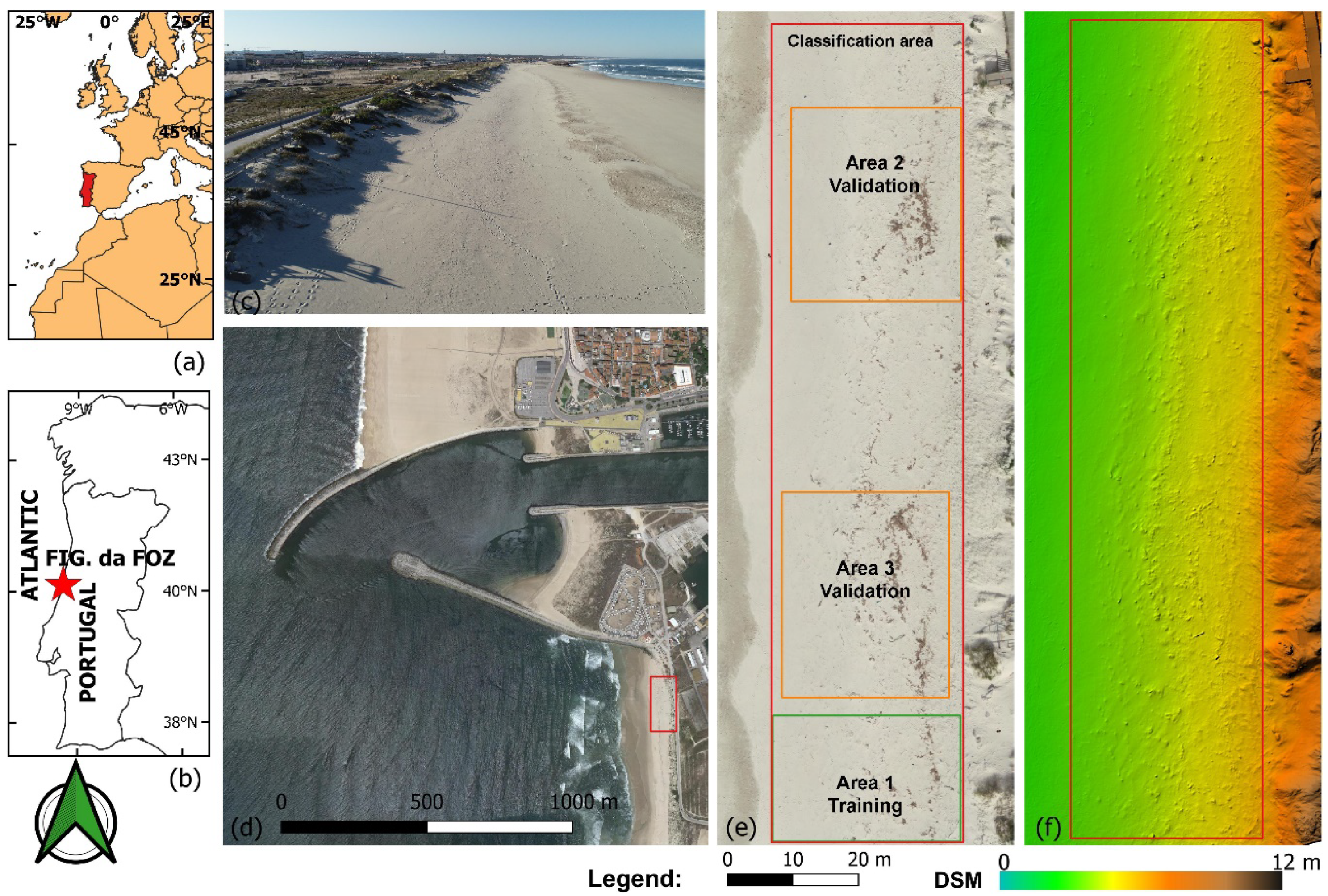
A simple, cost-effective, and UAS-based framework was used for generating MML abundance maps of sandy beaches, in compliance with European Directives [34]. This framework, described in Figure 1, was composed of four operational steps. First, a very low altitude UAS flight was planned and the corresponding ultrahigh resolution images were acquired over the targeted area. Then, the image block was processed using a Structure from Motion and Multi Video Stereo (SfM-MVS) processing workflow to generate the digital surface model (DSM) and the orthomosaic. In the third step, the MML items were detected in the orthomosaic by a supervised and OOML classifier, which used a minimal training effort. In the last step, abundance maps were created by using the centroids of the macro litter objects classified in the previous step.

2.1. Study Area

Cabedelo Beach (40°08′12.8″N and 8°51′47.5″W, Figure 2) is a sandy beach located on the western Portuguese coast facing the North Atlantic Ocean (OSPAR area 5, Iberian coast, [34]), southward Mondego River estuary (Figueira da Foz). The beach is backed by a stabilized dune, with a crest height that varies between 5 and 10 m moving southwards (see Figure 2).

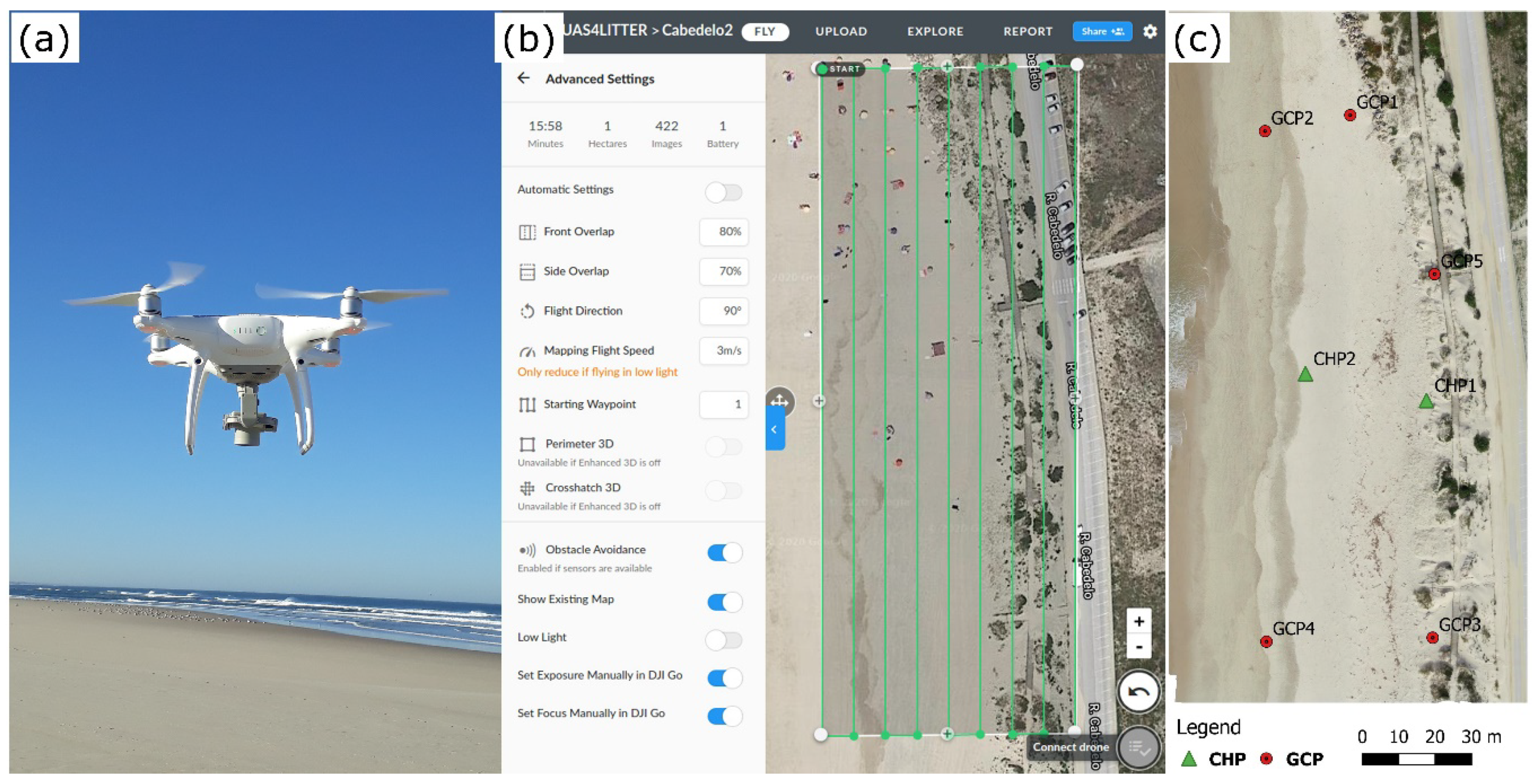
2.2. Field Data Acquisition and Unmanned Aerial Syetem (UAS) Survey

The acquisition of aerial images was performed with the quadcopter Phantom 4 Pro (Figure 3a) on 15 February 2019 at 12:30 a.m., a sunny day with clear sky and light wind. The choice of this aerial platform was driven by the need for the aircraft to be deployed in very small places and flown at a very low cruise speed. This rotary wing, which was significantly more affordable than most rotary wings, was equipped with a one-inch 20 megapixels CMOS (complementary metal oxide semicondutor) sensor (camera model FC6310, 24 mm full-frame equivalent) with a mechanical shutter. The camera was also combined with a three-axis brushless gimbal, that smooths the angular movements of the camera, dampens vibrations, and maintains the camera in a predefined position [35]. This component was essential to ensure good stabilization of the image acquisition process and to avoid blurring in the very low altitude images.
Concerning the image acquisition strategy and taking into account the current practices in UAS-based environmental monitoring [36], the following three main issues were considered: mission planning, UAS georeferencing accuracy, and camera settings. The mission planning must include all the parameters that allow the UAS to perform the flight autonomously. For nadiral image acquisition, the most important parameters are as follows: (i) nominal flight height, (ii) image overlap, (iii) geometry of surveyed area, and (iv) camera settings. On the basis of these parameters, the flight mission software computed, for the given camera model, the expected ground sampling distance (GSD) and the flight path (waypoints) to follow. In this work, mission planning was carried out using the freeware mobile application DroneDeploy (Figure 3b). The drone was set to fly at an altitude of 20 m, with the camera gimbal set to −90° for capturing photos perpendicular to the direction of the flight (Figure 3b). The images with a resolution of 4864 × 3648 pixels (aspect ratio 4:3) were overlapped with 80% front and 70% side rates. The final image nominal spatial resolution (GSD), was 5.5 mm.
In general, the positioning and image georeferencing accuracies of a UAS are driven by internal quality of the on-board Global Navigation Satellite System (GNSS) sensors. Using the waypoints computed by the mission planning software, the UAS performs an autonomous flight and records digital images with the specific camera settings at the indicated geographic positions. During the flight, the camera position and attitude are also recorded by the internal UAS GNSS sensors. However, Phantom 4 Pro navigation sensors are not accurate enough to perform a correct georeferencing of the derived geospatial products. Therefore, ground control points (GCPs) are needed for georeferencing digital surface model (DSM) and an orthomosaic in a specific cartographic coordinate system to eventually refine the auto-calibrated camera model. Along with GCPs, it is recommended to acquire additional points that can be used as independent check points (CHP) for assessing geometric accuracy of derived geospatial products. In order to maintain a low cost and simple approach, we acquired only five GCPs for georeferencing purposes and two CHPs for assessing the horizontal and vertical accuracy of the generated orthomosaic and DSM, respectively (Figure 3c).
Regarding camera settings, the overall exposure of each image has a significant impact on the geometric and radiometric quality of the final UAS-based geospatial products [37]. The ISO, aperture, and shutter speed are the three fundamental camera settings that determines the image exposure. In this work, ISO, shutter speed, and aperture were set to 100, 1/1250 s, and f/3.2, respectively, in order to accommodate the scene to daytime illumination conditions and to obtain sharp and well-exposed image data.

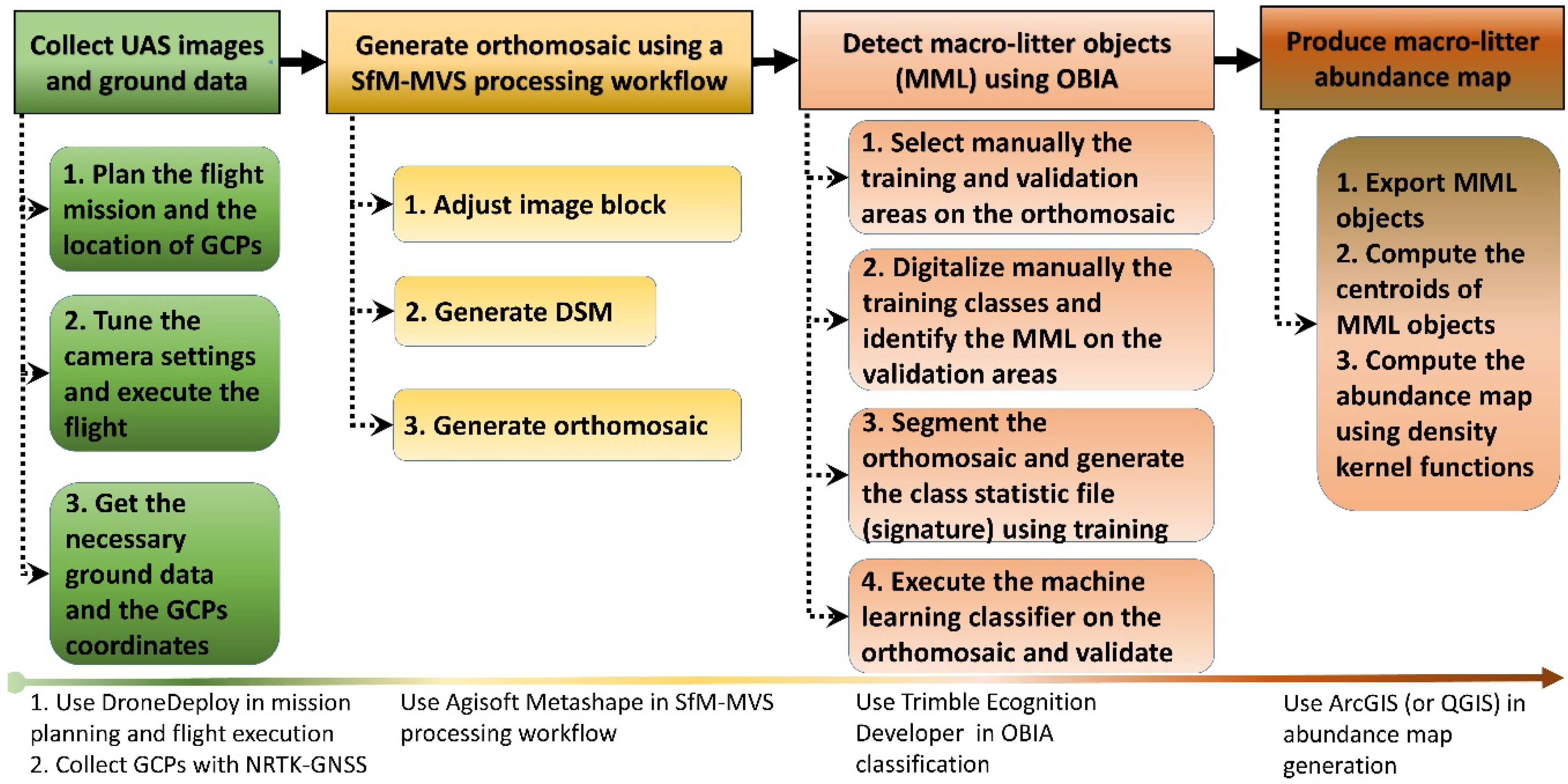
2.3. Structure from Motion and Multi Video Stereo (SfM-MVS) Processing

Generating a DSM (and the subsequent orthomosaic) from a block of overlapping images and processed with a SfM-MVS photogrammetric workflow requires that every part of the surface is imaged from two or more different positions [38,39]. The first step of this process consists of detecting features (keypoints) in each image and assigning a unique identifier to them, regardless of the image perspective and scale. The external orientation of the images (i.e., camera position and attitude) and the coordinates of the tiepoints (i.e., scene geometry) are then reconstructed simultaneously through the automatic identification of matching keypoints (tiepoints) in multiple images. These features, which are tracked from each image pair of the whole image block, allow one to estimate the initial camera positions and the object coordinates of tiepoints. Then, these initial values are simultaneously optimized in a bundle block adjustment (BBA), which minimizes the overall residual error and produces a self-consistent three-dimensional (3D) model with the associated camera parameters.
Agisoft Metashape (v. 1.5.3, [40]) was adopted as a Structure from Motion and Multi Video Stereo (SfM-MVS) processing software package to produce the digital surface model (DSM) and the related RGB orthomosaic. The processing strategy was divided into the following steps:
  • Photo alignment Using the keypoints detected on each image, the process computes the internal camera parameters (e.g., lens distortion), the external orientation parameters for each image, and generates a sparse 3D point cloud.
  • Georeferencing The geospatial 3D point cloud is assigned to a specific cartographic (or geographic) coordinate system.
  • Camera optimization Camera calibration and the estimation of its interior orientation parameters are refined by an optimization procedure, which minimizes the sum of re-projection errors and reference coordinate misalignments. For this step, the sparse point cloud is statistically analyzed to delete misallocated points and to find the optimal re-projection solution.
  • Dense matching The MVS dense matching technique generates a 3D dense point cloud from multiple images with optimized internal and external orientation parameters.
  • DSM and orthomosaic generation The DSM is interpolated from the 3D dense point cloud, and consequently, the orthomosaic is generated from this DSM. It is worthwhile to note that we imaged a scene with low variation in height relative to the flying height. Therefore, the extra time-consuming steps of mesh generation and 3D texture mapping were not necessary for the generation of the orthomosaic.

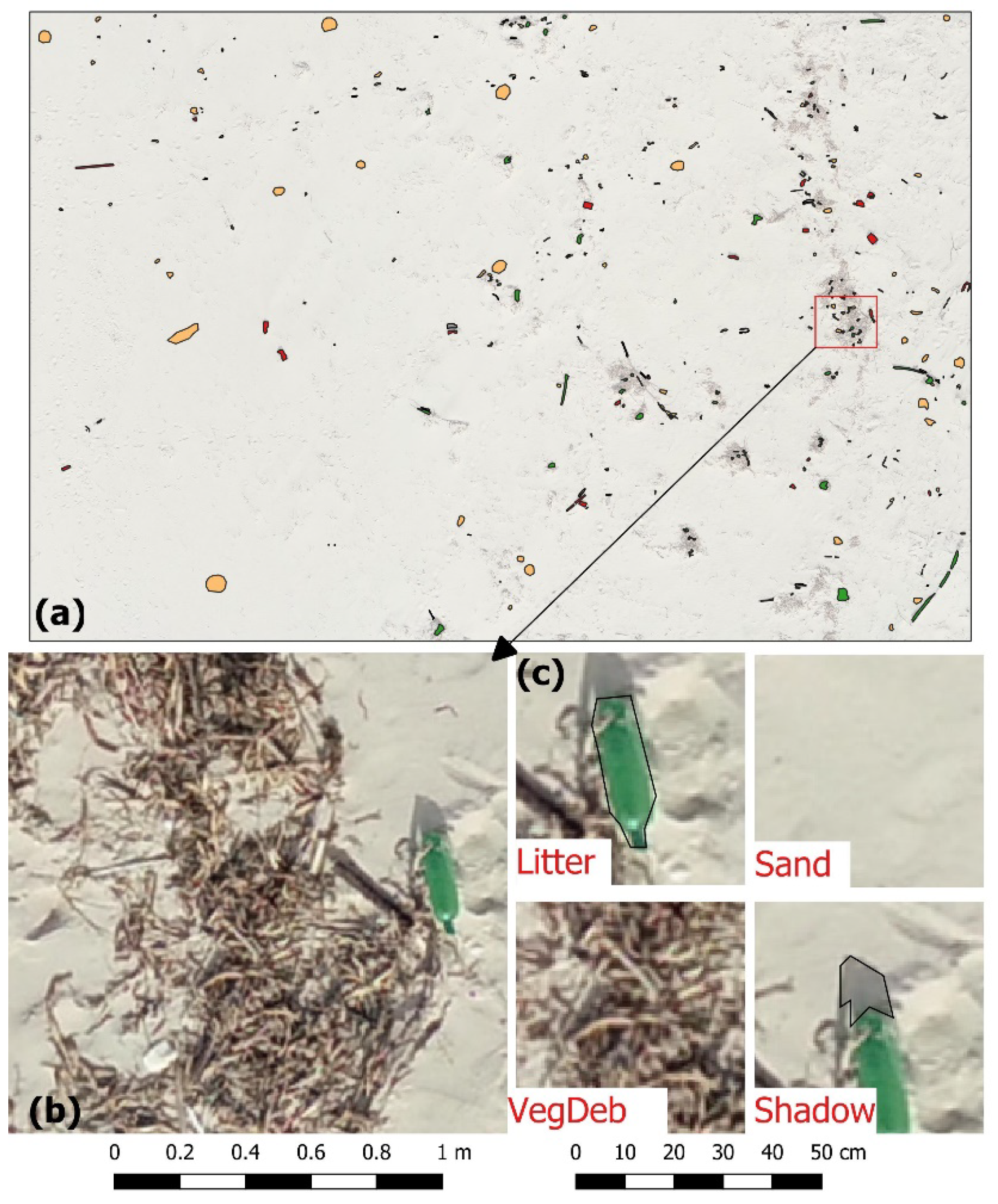
2.4. Classification Preprocessing, Nomenclature, and Training Areas

Before classification, the UAS-based orthomosaic was cropped to a manually digitized outline of the beach area that was monitored and where the MML was present. The aim of this preprocessing step was to either simplifying the beach cover nomenclature or minimizing the negative influences of non-beach areas (dune, rocs, and walkways) on the classification procedure.
Considering that we were interested in mapping MML abundance on a sandy beach, a nomenclature (classification scheme) was carefully selected and defined (Table 1 and Figure 4) taking into account that the corresponding classes were as follows: (i) mutually exclusive; (ii) exhaustive, and if necessary (iii) hierarchical [41].
The previously mentioned literature supports that, at least, image segmentation, training sample, feature space, and tuning parameters can have a significant impact on classification accuracy and efficiency [42,43]. Collecting adequate training data is a time-consuming and expertise demanding task. However, as we wanted to propose a simple, easy, and accessible OBIA classification approach, we decided to use a rectangular training area, outlined manually over the orthomosaic, where the variability of each beach cover class was well represented. After carefully inspecting the orthomosaic, this training area was located at the south part of the study area and represented only one-third of the total surface area to be classified. Within this training area, several polygons representing each class where manually digitized in a GIS environment (Figure 4).

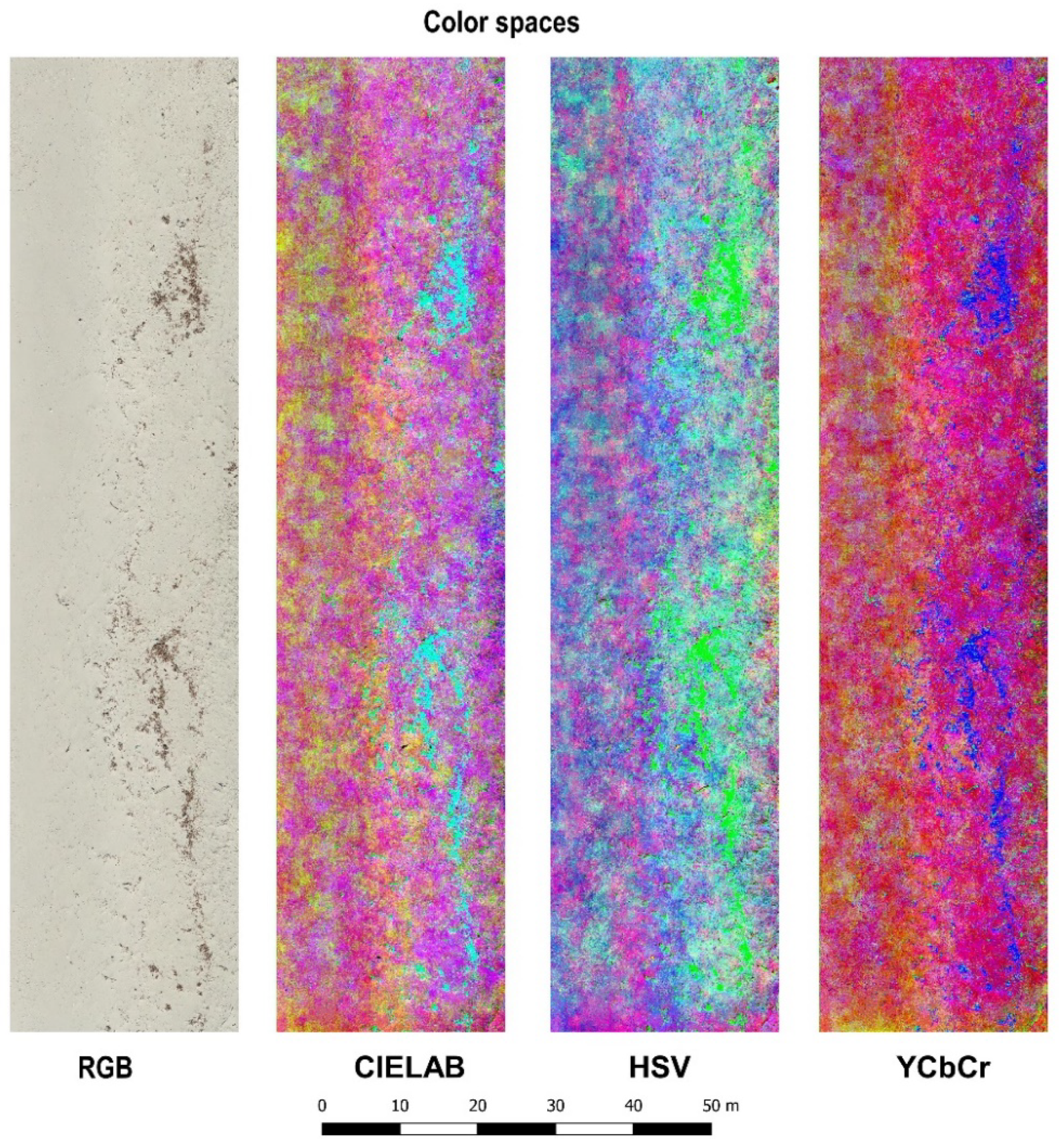
2.5. Feature Space and Data Normalization

Implementing a successfully OBIA classification requires careful selection of suitable discriminating features (or variables) such as spectral signatures, vegetation indices, transformed images, as well as textural and contextual information [44]. In our case, the spectral dimensionality was restricted to the RGB wavelengths of the low-cost onboard UAS camera which is sensitive to illumination intensity. The bands of the RGB wavelengths are highly correlated, mixing the color and intensity information, and in general this color space is not perceptually uniform [27]. To overcome these limitations, and considering that MML is generally characterized by its strong manufactured color, we used transformed image features described by the following three additional color spaces (see Figure 5): hue-based (HSV), perceptually uniform (CIE-Lab), and luminance-based YCbCr [45]. For each color space, the color is described differently from the RGB additive color model [46]. In HSV (hue, saturation, and value), the color information is only contained in the hue channel. In CIE-Lab, the color information is contained in two chromaticity layers, i.e., the red-green axis (a) and the blue-yellow axis (b). In YCbCr, the intensity or luminance (Y) is easily discriminated from the two chrominance components: the blue (Cb) and the red (Cr).
Considering that the color space transformations generated a mixture of spectral bands (RGB) with synthetic bands, data normalization was important for some classifiers to treat each band equally. For the SVM and KNN classifiers, bands were normalized by using linear scaling to produce a range from zero to one.

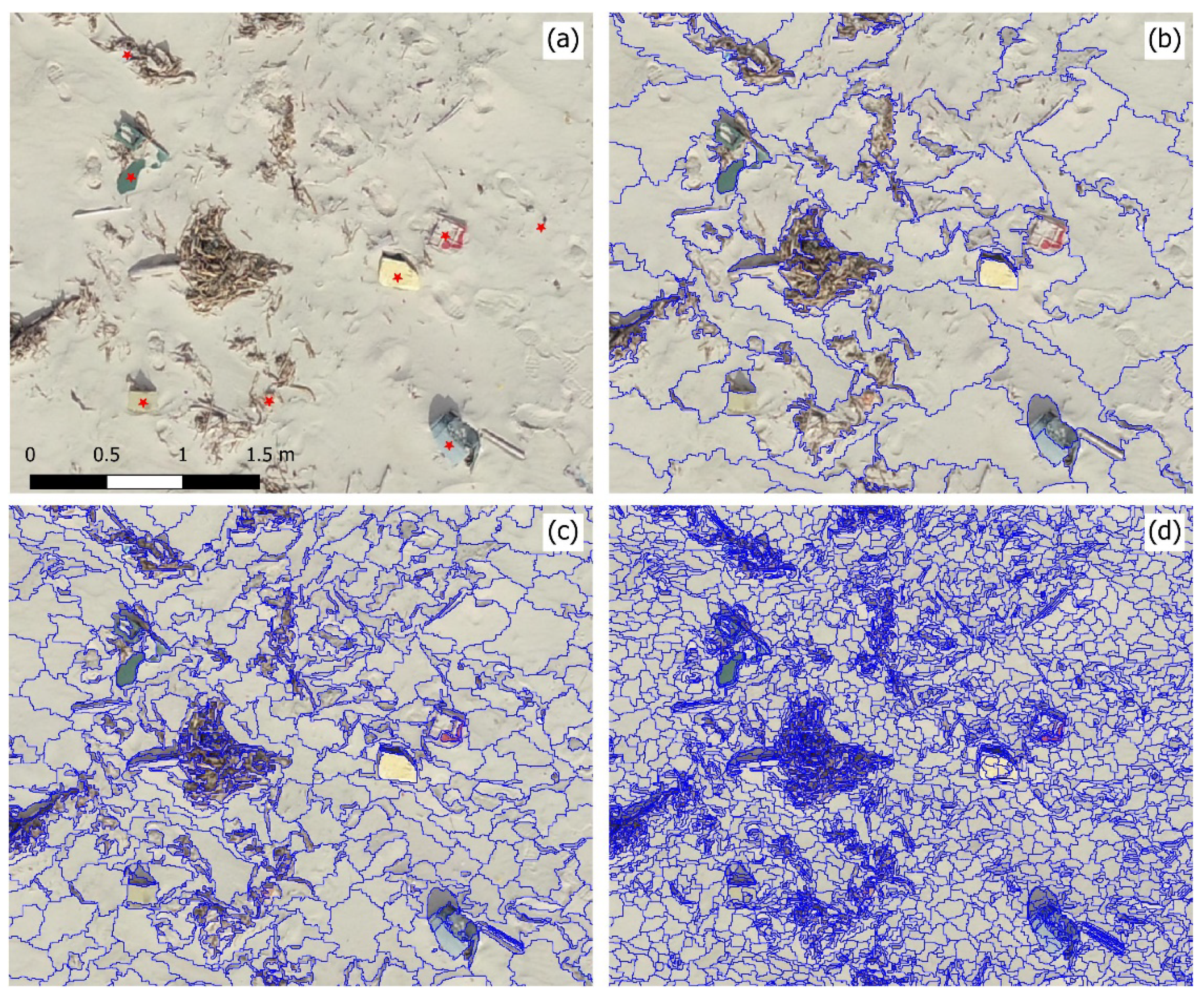
2.6. Image Segmentation

Segmentation is the process of dividing the image into non-overlapping image objects that are spatially and spectrally homogeneous. As a first and most critical step of OBIA classification [47], the quality of the image segmentation has a significant impact on the classification accuracy. Over-segmented objects which contain only a part of the target object class, and under-segmented objects which contain more than one target object class, both cause negative effects on the predicted class signatures [48].
In this study, the segmentation of the synthetic remote sensing image was realized with the multi-resolution image segmentation algorithm (MRIS) available in Trimble eCognition Developer® (usually known as eCognition) [49]. The MRIS is a bottom-up region growing technique driven by the following three main parameters: scale, shape and compactness. The most important is the scale parameter that controls the average size in pixels of the resulting image objects (a higher value results in larger objects). Shape and compactness define the object homogeneity and are weighted from zero to one. Shape controls how much the segmentation is influenced by the spectral (color) information versus the object shape information (a higher value means lower influence of color). Compactness also controls the object shape (a higher value means more compact objects but less spectrally homogeneous) [47]. The values of these three parameters were selected using an iterative trial and error process, combined with a visual analysis performed by an experienced operator. In order to find a single segmentation scale that would best separate the four cover classes and based on similar research on OBIA analysis of ultrahigh sub-decimeter UAS imagery [50], we started by fixing the values of the two parameters shape and compactness to 0.1 and 0.5, respectively. Then, the training area was segmented at seven segmentation scales, starting at 10 and ending at 80 by using scale increments of 10 (see Figure 6). The scale 30 was the best because it retained the individual marine litter items (Figure 6c); at a coarse scale (Figure 6b), these items were very often merged into broader image objects such as vegetation debris.

2.7. Classifiers and User-Defined Parameters

In the context of detecting MML items from an orthomosaic with ultrahigh resolution (sub-centimeter level), the following three supervised, non-parametric and object-oriented machine learning classifiers were evaluated: (1) RF, a decision-tree-based ensemble algorithm; (2) SVM, a statistical learning algorithm; and (3) KNN, an instance-based learning algorithm.

2.7.1. Random Forest

RF is an ensemble classifier that uses a large number of decision tree classifiers to assign a final class of the unknown object by majority voting of all decisions taken at each tree [51]. Each tree is constructed and trained automatically using a random set (in general, two thirds) of the training data (referred to as in-bag samples) and a random set of the variables [43]. The remaining training data (in general, one third) that is not used at each tree, is known as out-of-bag samples and is used in an internal cross-validation technique to provide an independent estimate of the overall accuracy of the RF classification [52]. In order to generate a prediction model, two important and user-defined parameters need to be set, i.e., the number of decisions trees to be generated (ntree) and the number of variables used in each node to make the tree grow (Mvar). The published literature has highlighted that the RF classifier is more sensitive to the Mvar parameter than to the ntree parameter [53]. Since the computational efficiency and the non-overfit properties of the RF classifier allows the error to stabilize before 500 trees are achieved, this number of trees is commonly assigned to the ntree parameter [43,52]. Regarding the Mvar parameter, the square root of the total number of variables is the value commonly used in classification problems [43]. However, in some software implementations (e.g., eCognition), the RF algorithm can be subject to the same parameters as decision trees (DT). These parameters include the following: (i) depth (Dep) to regularize each tree (i.e., to limit the way it grows) preventing overfitting; (ii) minimum number of samples (Ns) that a node must contain to consider splitting; (iii) maximum categories to cluster possible values of a categorical variable; and (iv) the use (or non-use) of surrogates to work with missing data [49]. The following additional eCognition parameters are: (i) active variables (Mvar); (ii) forest accuracy, for the desired level of accuracy, and (iii) termination criteria, which can be set to the maximum number of trees, forest accuracy, or both.

2.7.2. Support Vector Machine

According to the principle of statistical learning theory, the SVM constructs an optimal hyperplane (i.e., a decision surface) that separates the dataset into a discrete predefined number of classes in a way consistent with the training examples [54]. The amount of training data that can be misclassified (e.g., on the wrong side of the hyperplane) is controlled by a positive user-defined parameter C (the cost parameter). A large C value decreases the number of misclassified objects, but can create an overfitted model that may not be adequate to classify new data [55]. When it is not possible to separate the classes linearly, kernel functions are used to project the input data into a high-dimensional feature space that increases the separability of these classes in this feature space [56]. The most commonly used kernel functions in remote sensing are linear, polynomial, and radial basis function (RBF) which is controlled by the gamma (Υ) parameter [52]. Adjusting the value of Υ changes the shape of the decision boundary; smaller values mean a smoother boundary, whereas higher values mean a more complex boundary. In eCognition, the SVM classifier was implemented with the following configurable parameters: (i) C, (ii) kernel function (linear or radial basis function), and (iii) gamma (for RBF only). The optimal values of C and Υ are often determined by using the grid search method (also known as exhaustive search), which uses a large range (search interval) of different pairs of parameters and the one having the highest classification accuracy rate in this interval is selected [57].

2.7.3. K-Nearest Neighbor

KNN is a relatively simple instance-based learning approach. An object is classified based on the weighted average value of the class attributes of its k spectrally nearest neighbor (e.g., k = 5) in the training set [58]. The performance of this classifier is mainly influenced by the key parameter k [55]. In eCognition. the KNN was implemented with only one configurable parameter, k.

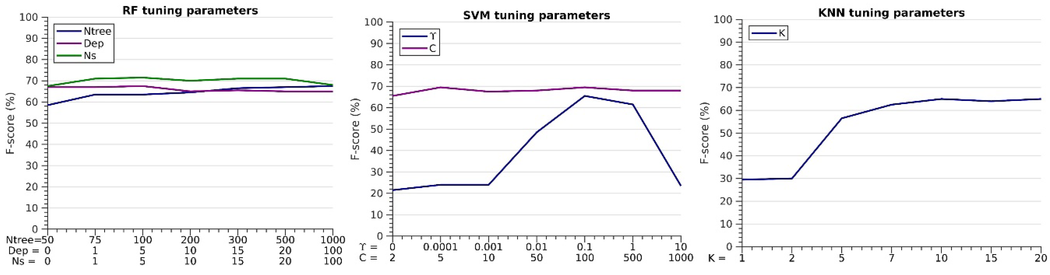
2.8. Tuning the Primary Classifier Parameters

The strategy used for tuning the classifier was to modify one by one each of the primary parameters, while maintaining the others fixed. For RF, we started with the default values and we modified successively the ntree, depth, and Ns, one parameter at a time. For SVM, we also started with the default values and we modified successively the Υ and C parameters, one at a time. For KNN, only the number of neighbors (K) was tuned, since it was the only implemented parameter.

2.9. Performance Assessment

In order to have a valuable reference for evaluating the performance detection of the classifiers, the RGB orthomosaic map was visually screened and manually processed by an operator in the GIS environment. For each object recognized as marine litter item by the operator, the approximated center of marine litter item shapes was marked. For further details about the manual procedure and the type of MML encountered at Cabedelo beach, please refer to Gonçalves et al. [26,27].
The automated detection performances were evaluated with the F-score statistical analysis. The centroid of all the objects labeled as MML by the algorithms were compared to the centroids of MML objects delineated manually in the testing areas. When the distance between the centroids was smaller than 20 cm (setup threshold), the detection was marked as true positive (TP), otherwise as false positive (FP).
Finally, all the marine litter items not detected by the automated algorithm were counted as false negatives (FN). In detail, the precision (P) is a measure of the method to not generate false positives and is defined as:
P ( % ) = T P T P + F P × 100
To measure the sensitivity of each method to not generate false negatives we use the recall (R), which is given by:
R ( % ) = T P T P + F N × 100
The F-score (F) is a measure of the overall quality of the method and combines the previous P and R metrics as:
F ( % ) = 2 P   R P + R × 100
It also varies between 0% and 100%, where 0% means no correlation between the predicted and observed MML items and 100% means a perfect classification (i.e., a perfect match).

2.10. Quantifying Macro Litter Abundance

Quantifying and mapping the abundance of MML on coastal areas is an important issue to understand the dynamics of their deposition, to compute accumulation rates, and to identify spatial distribution patterns over time for improving the planning of clean-up operations [28,29]. In this study, kernel density estimators (KDE) were used for quantifying the MML abundance. First, the polygonal macro litter items detected by a particular OOML method were converted to point features using the centroid of these polygonal features. Then, using a KDE function, these point events (i.e., the centroids of the macro litter items) were transformed into a continuous surface that represented the point density (i.e., the number of MML items per square meter) in a two-dimensional (2D) space [59]. The two key parameters of a planar KDE function are the kernel function and the search bandwidth. However, there is consensus that the choice of the bandwidth that determines the smoothness of the density surface is more important than the choice of the kernel function [60]. In this work, the quartic function was used for estimating the MML density at each cell of the orthomosaic image. In addition, to generate a smooth MML abundance map, a sufficiently large bandwidth of 10 m was chosen.

3. Results

3.1. Georeferencing Accuracy

The geometric accuracy of the SfM-MVS processing workflow was evaluated by using the reprojection error of the tie points (0.2 pix), the RMSE of 5 GCPs (1.0 cm in XY and 2.5 cm in Z), and the RMSE of 2 CHPs (1.5 cm in XY and 3.4 cm in Z). Using these two CHPs we assessed the accuracy of the orthomosaic (0.4 cm in XY) and the DSM (2.8 cm in Z). Overall, the accuracy of the two geospatial products exported from Agisoft MetaShape (the orthomosaic and the DSM with spatial resolutions of 5.5 and 7.6 mm, respectively) are in same level as the NTRIP-GNSS method used for georeferencing, which are suitable for mapping the MML abundance.

3.2. Effects of the Tuning Parameters on the F-Score

For each machine learning, the effect of the tuning parameters had a different impact on the F-score (Figure 7). Running the RF with the default parameters (ntree = 50, Dep = 0, and Ns = 0), a mean F-score of 59% was achieved for the two validation areas (A1 and A2). Running the SVM with the default values (Υ = 0 and C = 2), a mean F-Score of 22% was achieved. Running the KNN with the default values (K = 1), a mean F-score of 30% was observed. These findings are in agreement with those presented in [55], highlighting that the default parameters are not appropriate for this work and must be tuned.
Regarding the RF optimization, choosing the default values of depth and Ns, the best F-score was achieved for ntree = 500. Setting the values ntree = 500, Ns = 0 (default), and varying the Dep value, the best F-score was obtained for Dep = 5. Setting the values of ntree = 500 and Dep = 5, the best F-score was obtained for NS = 5. Concerning the SVM, the best tuning parameters were obtained setting firstly the default of C = 2 and varying the values of Υ, obtaining the best F-score for Υ = 0.1. Finally, using Υ = 0.1 and varying the values of C, the best F-score was obtained for C = 5. For KNN, the procedure was straightforward with the best F-score obtained for K = 10 (Figure 7).

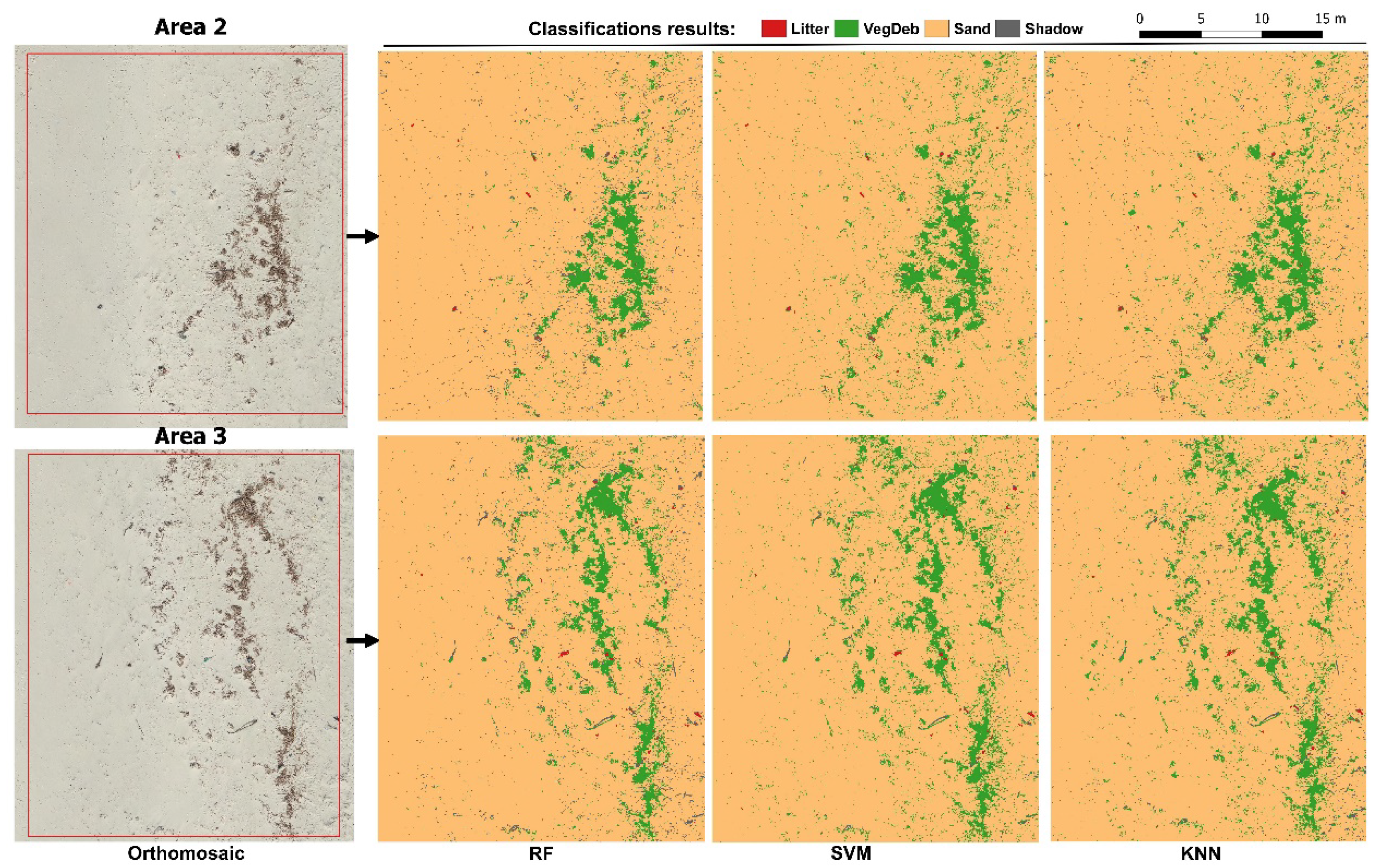
3.3. Comparisons of the Classifiers for Mapping Marine Litter

In the previous section, for deriving the optimized parameters of each machine learning classifier, 42 beach cover maps were generated, i.e., 21 for the RF, 14 for the SVM, and seven for the KNN. Details of these classification maps obtained with the optimized parameters of each machine learning classifier are shown in Figure 8.
Although the classifications maps are visually quite similar, a detailed analysis about the detection performance of the MML class showed significant differences among the three machine learning algorithms (see Table 2). First, we found that for each validation area the detection performance obtained by each machine learning method was very similar. Second, RF registered the highest number of TP with a mean recall of 67%. Third, SVM returned the lowest number of FP, thus, the highest precision (77% on average). Fourth, KNN had the worst performance in terms of F-score, although results did not differ significantly from SVM and RF. Overall, the averaged F-score slightly varied between the three machine learnings techniques, with 65% for KNN, 68% for SVM, and 72% for RF.

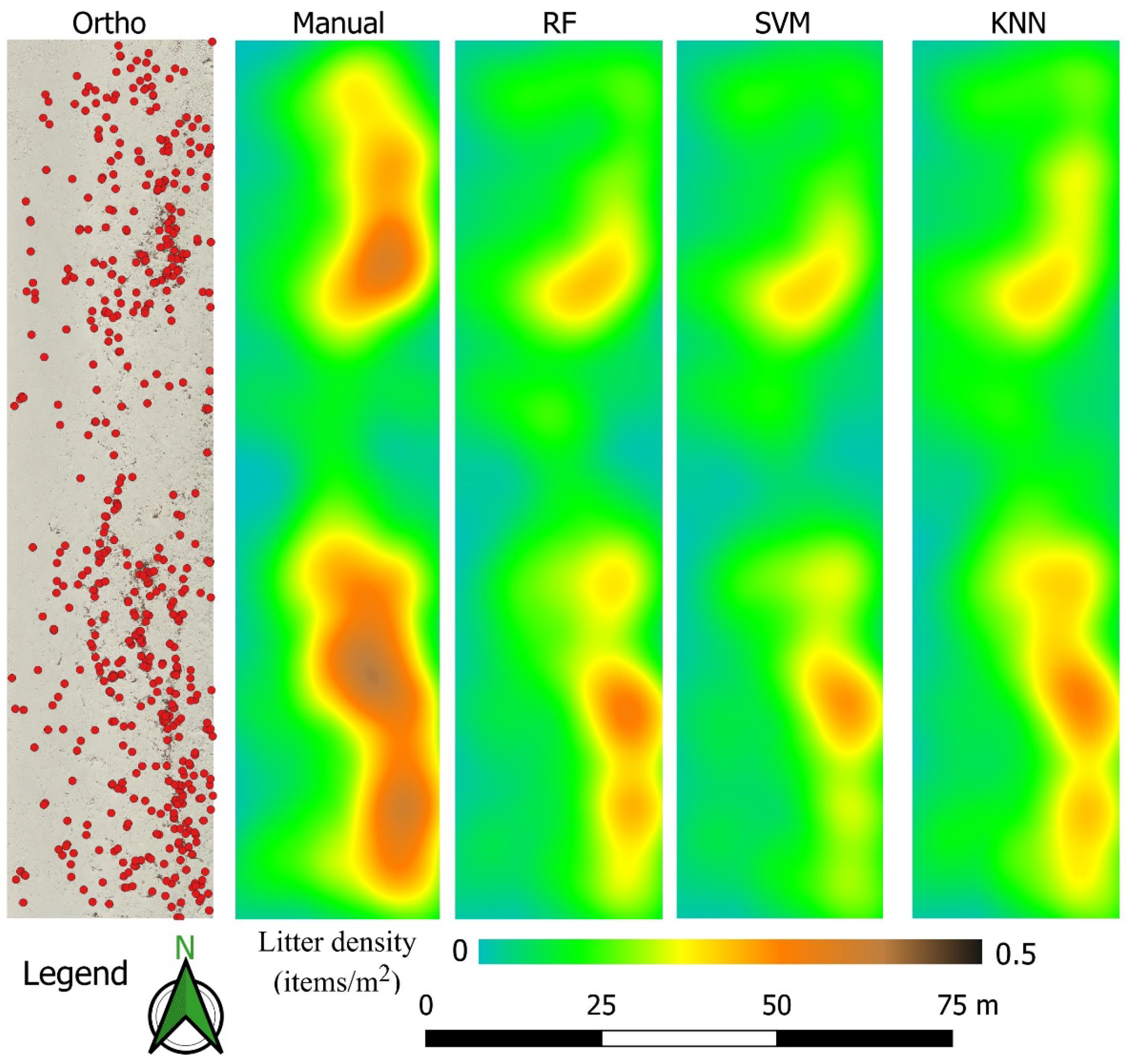
3.4. Mapping Marine Litter Abundance

The MML class objects detected by each optimized OOML classifier are exported as 2D polygon shapefiles and converted to a point geometry using the centroids of polygons in a GIS environment. Using the planar KDE function available on ArcGIS, each point layer was, then, converted to a density map representing the MML abundance (Figure 9). In order to evaluate the performance of each classifier to map MML abundance, the orthomosaic was manually screened by an experienced operator to produce a reference dataset of the centroids of the MML items present at the beach. Then, this reference dataset was used to generate the reference MML abundance map which in turn was employed to evaluate, visually and quantitatively, the performance of each classifier. Figure 9 shows the centroids of the MML items manually screened in the orthomosaic and the MML abundance maps obtained manually and automatically using the three OOML classifiers (RF, SVM, and KNN). All three OOML classifiers returned MML accumulation patterns that were visually consistent with the manual method, identifying two main MML clusters at the beach area. In addition, we found a strong correlation between the manual abundance map and each OOML abundance map, with R2 (r-square) values of 0.79 (RMSE 0.028 items/m2) for RF, 0.76 (RMSE 0.027 items/m2) for SVM, and 0.83 (RMSE 0.026 items/m2) for KNN.

4. Discussion

4.1. UAS Type and Flight Mission

In environmental monitoring, the acquisition of aerial images with UAS platforms is commonly performed by the following two categories of systems: multirotor and fixed wing. These two systems have different performances in terms of takeoff capabilities, payload, flight time, cruise speed, and stability of image acquisition. Fixed wing UASs have very good flight endurance, high cruise speeds, and can cover large areas in one flight. However, they require a suitable landing area and skills for taking off and landing them softly to avoid damage to the aircraft and payload sensors. Multirotor UASs are easy to fly, including takeoff, and landing. In addition, the cruise speed can also be as low as necessary. In this work, the multirotor option was chosen due to its low cruise speed and its vertical takeoff and landing (VTOL) capabilities, which allowed the UAS to be deployed at very small areas of the beach. Nevertheless, the short operational time of the multirotor battery limits the flight time and restricts the extent of the beach area to be surveyed. In this study, one battery allowed an operational flight time of about 27 min. Using the current flight planning settings (Section 2.2), we were able to scan a beach area of ~2 ha (370 × 65 m) with eight parallel flight lines. In this context, to extend the scanned area, it has been suggested to fly multi-battery missions using specialized UAS flight mission and autopilot software (e.g., DroneDeploy and DJI MapPilot) with a resume feature [36]. In addition, the recent availability of off-the-shelf UASs incorporating onboard RTK-GNSS sensors, has generated high accuracy and precise geospatial products [61], removing the time-consuming framework steps of preflight GCP and CHP displacements and the post-flight acquisition of their coordinates.

4.2. Object-Oriented Machine Learning Methods

In contrast to previous studies conducted by different authors [22,23,62], in this work, the MML detection on the orthomosaic with ultrahigh spatial resolution was preferable to the use of single UAS-based imagery, because the subsequent generation of a georeferenced abundance map was a straightforward step. The OBIA classification approach based on the proposed nomenclature was efficient for extracting the MML class and proved to be well suited for transferring the process to other orthomosaic areas. In fact, the mean values of the 12 composite bands collected for all the object classes on the training area could be applied directly on the other orthomosaic areas without any editing. Using a tiling and stitching approach implemented in the server version of eCognition, the proposed classification approach could be used to detect MML items over larger orthomosaic areas, as long as the beach substrate remained similar to the training area where the class statistics were collected. The comparison among the three OOML classifiers showed that RF obtained better results than SVM and KNN. However, when we compared the automated abundance maps with the one produced manually, the map generated by the KNN classifier achieved the best correlation factor.
Once color was the key element for detecting MML, colored items similar to the sand color were not detected; they were included in the sand class. In this context, it was expected that the use of the volume of the MML items derived from the DSM would decrease the number of false positives [63]. However, the heights of the MML objects were not expressive, and hence, the DSM was not used for this purpose. Inaccurate classification was also due to the low payload capabilities of the low-cost UAS, since the images were acquired by an inexpensive off-the-shelf camera. Its low radiometric quality and low spectral resolution were significantly influenced by the lighting and atmospheric conditions. To mitigate the impact of lighting and atmospheric conditions on the accuracy of litter detection and to maximize the contrast between the sand and the colored litter items, it has been suggested to fly in similar geometric lighting and sunny conditions [31,64]. Future work should explore the feasibility of using multispectral sensor products for automatically categorizing marine litter items, which are expected to have a unique reflectance response based on their color and material (e.g., [65]).
It is worth mentioning that we were interested in mapping only one land cover beach class (i.e., the MML class). The use of a supervised multiclass classifier may not necessarily be an appropriate approach because these classifiers require considerable effort to produce an exhaustive and mutually exclusive training dataset, which should include all classes present in the area of interest [66,67]. However, when only two classes were considered (litter and non-litter), the labeling accuracy of the RF classifier was decreased significantly, i.e., approximately 35% (F-score 44%).
In comparison with previous works [22,23,26], the OOML classifiers presented here were simpler to use for inexperienced analysts, achieved a similar (sometimes a slightly better) F-score, and did not show any particular issue regarding the shadows and the transparent objects. While the absolute segmentation and OOML parameters could have different values for different spatial resolutions (different flying heights) and in different beaches with different substrate, we expect that the proposed classification workflow would offer reliable guidance for selecting and tuning these parameters.

5. Conclusions

This study showed that a consumer-grade UAS combined with SfM-MVS methods can be used effectively for generating an ultrahigh resolution orthomosaic (sub-centimeter level) and for monitoring sandy beaches polluted by MML. The low spectral resolution of the orthomosaic was overcome by combining four color spaces (RGB, CIE-Lab, HSV, and YCbCr) with an OBIA approach which proved to be highly suitable for extracting marine MML objects from ultrahigh resolution imagery.
After being optimally tuned, the three compared object-oriented machine learning (OOML) classifiers, namely random forest (RF), support vector machine (SVM), and k-nearest neighbor (KNN), were shown to have quite similar performances (F-score) for detecting colored MML objects. Although the RF had more parameters to be tuned, and therefore appeared to be more complex to optimize, the number of trees (ntree) was the most influencing parameter. On the contrary, for the KNN, which had one parameter to be tuned, the F-score was slightly worse than the other two machine learning classifiers. Nevertheless, the MML abundance map generated from KNN was well correlated with the abundance map produced manually. This suggests that this OOML classifier can be used effectively by nonexpert remote sensing analysts in a simple MML abundance map framework.
The synergistic use of small UAS with OOML classifiers is a major step towards cost-effective and efficient operational programs for monitoring MML abundance and detecting hotspots on sandy beaches, as they can be easily implemented by local, municipal, and national environmental agencies.
Future research should focus on the use of one-class classifiers with minimal labeling effort to generate abundance maps from an ultrahigh resolution orthomosaic obtained by a consumer-grade UAS incorporating RTK-GNSS sensors.

Author Contributions

Conceptualization, G.G. and U.A.; methodology, G.G. and U.A.; formal analysis, G.G., U.A., and L.G.; data curation, G.G., U.A., and F.B.; writing—original draft preparation, G.G. and U.A.; writing—review and editing, G.G., U.A., L.G., P.S., and F.B.; project administration, G.G. and F.B.; funding acquisition, G.G. and F.B. All authors have read and agreed to the published version of the manuscript.

Funding

This work was supported by the Portuguese Foundation for Science and Technology (FCT) and by the European Regional Development Fund (FEDER) through COMPETE 2020, Operational Program for Competitiveness and Internationalization (POCI) in the framework of UIDB 00308/2020 and the research project UAS4Litter (PTDC/EAM-REM/30324/2017). The work of F.B. was supported by the University of Coimbra through contract IT057-18-7252. F.B. and P.S. acknowledge FCT through the strategic project UIDB/04292/2020 granted to MARE.

Conflicts of Interest

The authors declare no conflict of interest. The funders had no role in the design of the study; in the collection, analyses, or interpretation of data; in the writing of the manuscript, or in the decision to publish the results.

References

  1. Fleming, L.E.; Broad, K.; Clement, A.; Dewailly, E.; Elmir, S.; Knap, A.; Pomponi, S.A.; Smith, S.; Solo Gabriele, H.; Walsh, P. Oceans and human health: Emerging public health risks in the marine environment. Mar. Pollut. Bull. 2006, 53, 545–560. [Google Scholar] [CrossRef] [PubMed] [Green Version]
  2. Galgani, F.; Hanke, G.; Maes, T. Global distribution, composition and abundance of marine litter. In Marine Anthropogenic Litter; Springer: Cham, Switzerland, 2015; ISBN 9783319165103. [Google Scholar]
  3. Veiga, J.M.; Fleet, D.; Kinsey, S.; Nilsson, P.; Vlachogianni, T.; Werner, S.; Galgani, F.; Thompson, R.C.; Dagevos, J.; Gago, J.; et al. Identifying Sources of Marine Litter. MSFD GES TG Marine Litter Thematic Report; Publications Office of the European Union: Luxembourg, 2016; ISBN 9789279645228. [Google Scholar]
  4. Ogunola, O.S.; Onada, O.A.; Falaye, A.E. Mitigation measures to avert the impacts of plastics and microplastics in the marine environment (a review). Environ. Sci. Pollut. Res. 2018, 25, 9293–9310. [Google Scholar] [CrossRef] [PubMed]
  5. Munari, C.; Corbau, C.; Simeoni, U.; Mistri, M. Marine litter on Mediterranean shores: Analysis of composition, spatial distribution and sources in north-western Adriatic beaches. Waste Manag. 2016, 49, 483–490. [Google Scholar] [CrossRef] [PubMed]
  6. Ríos, N.; Frias, J.P.G.L.; Rodríguez, Y.; Carriço, R.; Garcia, S.M.; Juliano, M.; Pham, C.K. Spatio-temporal variability of beached macro-litter on remote islands of the North Atlantic. Mar. Pollut. Bull. 2018, 133, 304–311. [Google Scholar] [CrossRef] [PubMed]
  7. Galgani, F. Marine litter, future prospects for research. Front. Mar. Sci. 2015, 2, 1–5. [Google Scholar] [CrossRef] [Green Version]
  8. Schulz, M.; Clemens, T.; Förster, H.; Harder, T.; Fleet, D.; Gaus, S.; Grave, C.; Flegel, I.; Schrey, E.; Hartwig, E. Statistical analyses of the results of 25 years of beach litter surveys on the south-eastern North Sea coast. Mar. Environ. Res. 2015, 109, 21–27. [Google Scholar] [CrossRef]
  9. Schulz, M.; van Loon, W.; Fleet, D.M.; Baggelaar, P.; van der Meulen, E. OSPAR standard method and software for statistical analysis of beach litter data. Mar. Pollut. Bull. 2017, 122, 166–175. [Google Scholar] [CrossRef]
  10. Oigman-Pszczol, S.S.; Creed, J.C. Quantification and Classification of Marine Litter on Beaches along Armação dos Búzios, Rio de Janeiro, Brazil. J. Coast. Res. 2007, 232, 421–428. [Google Scholar] [CrossRef]
  11. Kusui, T.; Noda, M. International survey on the distribution of stranded and buried litter on beaches along the Sea of Japan. Mar. Pollut. Bull. 2003, 47, 175–179. [Google Scholar] [CrossRef]
  12. Zhou, P.; Huang, C.; Fang, H.; Cai, W.; Li, D.; Li, X.; Yu, H. The abundance, composition and sources of marine debris in coastal seawaters or beaches around the northern South China Sea (China). Mar. Pollut. Bull. 2011, 62, 1998–2007. [Google Scholar] [CrossRef]
  13. Hong, S.; Lee, J.; Kang, D.; Choi, H.W.; Ko, S.H. Quantities, composition, and sources of beach debris in Korea from the results of nationwide monitoring. Mar. Pollut. Bull. 2014, 84, 27–34. [Google Scholar] [CrossRef] [PubMed]
  14. Prevenios, M.; Zeri, C.; Tsangaris, C.; Liubartseva, S.; Fakiris, E.; Papatheodorou, G. Beach litter dynamics on Mediterranean coasts: Distinguishing sources and pathways. Mar. Pollut. Bull. 2018, 129, 448–457. [Google Scholar] [CrossRef] [PubMed]
  15. Williams, A.T.; Randerson, P.; Di Giacomo, C.; Anfuso, G.; Macias, A.; Perales, J.A. Distribution of beach litter along the coastline of Cádiz, Spain. Mar. Pollut. Bull. 2016, 107, 77–87. [Google Scholar] [CrossRef] [PubMed]
  16. Frias, J.P.G.L.; Antunes, J.C.; Sobral, P. Local marine litter survey—A case study in Alcobaça municipality, Portugal. Rev. Gestão Costeira Integr. 2013, 13, 169–179. [Google Scholar] [CrossRef]
  17. Eriksson, C.; Burton, H.; Fitch, S.; Schulz, M.; van den Hoff, J. Daily accumulation rates of marine debris on sub-Antarctic island beaches. Mar. Pollut. Bull. 2013, 66, 199–208. [Google Scholar] [CrossRef]
  18. Storrier, K.L.; McGlashan, D.J. Development and management of a coastal litter campaign: The voluntary coastal partnership approach. Mar. Policy 2006, 30, 189–196. [Google Scholar] [CrossRef]
  19. Rees, G.; Pond, K. Marine litter monitoring programmes—A review of methods with special reference to national surveys. Mar. Pollut. Bull. 1995, 30, 103–108. [Google Scholar] [CrossRef]
  20. Haseler, M.; Schernewski, G.; Balciunas, A.; Sabaliauskaite, V. Monitoring methods for large micro- and meso-litter and applications at Baltic beaches. J. Coast. Conserv. 2018, 22, 27–50. [Google Scholar] [CrossRef]
  21. GESAMP. Guidelines for the Monitoring and Assessment of Plastic Litter in the Ocean; GESAMP Joint Group of Experts on the Scientific Aspects of Marine Environmental Protection: London, UK, 2019. [Google Scholar]
  22. Fallati, L.; Polidori, A.; Salvatore, C.; Saponari, L.; Savini, A.; Galli, P. Anthropogenic Marine Debris assessment with Unmanned Aerial Vehicle imagery and deep learning: A case study along the beaches of the Republic of Maldives. Sci. Total Environ. 2019, 693, 133581. [Google Scholar] [CrossRef]
  23. Martin, C.; Parkes, S.; Zhang, Q.; Zhang, X.; McCabe, M.F.; Duarte, C.M. Use of unmanned aerial vehicles for efficient beach litter monitoring. Mar. Pollut. Bull. 2018, 131, 662–673. [Google Scholar] [CrossRef] [Green Version]
  24. Bao, Z.; Sha, J.; Li, X.; Hanchiso, T.; Shifaw, E. Monitoring of beach litter by automatic interpretation of unmanned aerial vehicle images using the segmentation threshold method. Mar. Pollut. Bull. 2018, 137, 388–398. [Google Scholar] [CrossRef] [PubMed]
  25. Deidun, A.; Gauci, A.; Lagorio, S.; Galgani, F. Optimising beached litter monitoring protocols through aerial imagery. Mar. Pollut. Bull. 2018, 131, 212–217. [Google Scholar] [CrossRef] [PubMed]
  26. Gonçalves, G.; Andriolo, U.; Pinto, L.; Duarte, D. Mapping marine litter with Unmanned Aerial Systems: A showcase comparison among manual image screening and machine learning techniques. Mar. Pollut. Bull. 2020, 155, 111158. [Google Scholar] [CrossRef]
  27. Gonçalves, G.; Andriolo, U.; Pinto, L.; Bessa, F. Mapping marine litter using UAS on a beach-dune system: A multidisciplinary approach. Sci. Total Environ. 2020, 706, 135742. [Google Scholar] [CrossRef] [PubMed]
  28. Andriolo, U.; Gonçalves, G.; Bessa, F.; Sobral, P. Mapping marine litter on coastal dunes with unmanned aerial systems: A showcase on the Atlantic Coast. Sci. Total Environ. 2020, 736, 139632. [Google Scholar] [CrossRef]
  29. Merlino, S.; Paterni, M.; Berton, A.; Massetti, L. Unmanned Aerial Vehicles for Debris Survey in Coastal Areas: Long-Term Monitoring Programme to Study Spatial and Temporal Accumulation of the Dynamics of Beached Marine Litter. Remote Sens. 2020, 12, 1260. [Google Scholar] [CrossRef] [Green Version]
  30. Publications Office of the EU. Guidance on Monitoring of Marine Litter in European Seas. Available online: https://op.europa.eu/en/publication-detail/-/publication/76da424f-8144-45c6-9c5b-78c6a5f69c5d/language-en (accessed on 16 July 2020).
  31. Lo, H.S.; Wong, L.C.; Kwok, S.H.; Lee, Y.K.; Po, B.H.K.; Wong, C.Y.; Tam, N.F.Y.; Cheung, S.G. Field test of beach litter assessment by commercial aerial drone. Mar. Pollut. Bull. 2020, 151, 110823. [Google Scholar] [CrossRef]
  32. Kataoka, T.; Hinata, H.; Kako, S. A new technique for detecting colored macro plastic debris on beaches using webcam images and CIELUV. Mar. Pollut. Bull. 2012, 64, 1829–1836. [Google Scholar] [CrossRef]
  33. Blaschke, T. Object based image analysis for remote sensing. ISPRS J. Photogramm. Remote Sens. 2010, 65, 2–16. [Google Scholar] [CrossRef] [Green Version]
  34. OSPAR Commission. Guideline for Monitoring Marine Litter on the Beaches in the OSPAR Maritime Area; OSPAR Commission: London, UK, 2010; Volume 1. [Google Scholar]
  35. Gašparović, M.; Jurjević, L. Gimbal influence on the stability of exterior orientation parameters of UAV acquired images. Sensors 2017, 17, 401. [Google Scholar] [CrossRef] [Green Version]
  36. Tmušić, G.; Manfreda, S.; Aasen, H.; James, M.R.; Gonçalves, G.; Ben-Dor, E.; Brook, A.; Polinova, M.; Arranz, J.J.; Mészáros, J.; et al. Current Practices in UAS-based Environmental Monitoring. Remote Sens. 2020, 12, 1001. [Google Scholar] [CrossRef] [Green Version]
  37. O’Connor, J.; Smith, M.J.; James, M.R. Cameras and settings for aerial surveys in the geosciences. Prog. Phys. Geogr. 2017, 41, 325–344. [Google Scholar] [CrossRef] [Green Version]
  38. Eltner, A.; Sofia, G. Structure from motion photogrammetric technique. Dev. Earth Surf. Process. 2020, 23, 1–24. [Google Scholar]
  39. Smith, M.W.; Carrivick, J.L.; Quincey, D.J. Structure from motion photogrammetry in physical geography. Prog. Phys. Geogr. 2015, 40, 247–275. [Google Scholar] [CrossRef]
  40. Agisoft LLC. Agisoft Metashape User Manual; Version 1.5; Agisoft LLC: Saint Petersburg, Russia, 2019. [Google Scholar]
  41. Jensen, J.R. Introductory Digital Image Processing: A Remote Sensing Perspective, 4th ed.; Prentince Hall: Upper Saddle River, NJ, USA, 2005; ISBN 9780134058160. [Google Scholar]
  42. Duro, D.C.; Franklin, S.E.; Dubé, M.G. A comparison of pixel-based and object-based image analysis with selected machine learning algorithms for the classification of agricultural landscapes using SPOT-5 HRG imagery. Remote Sens. Environ. 2012, 118, 259–272. [Google Scholar] [CrossRef]
  43. Belgiu, M.; Drăgu, L. Random forest in remote sensing: A review of applications and future directions. ISPRS J. Photogramm. Remote Sens. 2016, 114, 24–31. [Google Scholar] [CrossRef]
  44. Lu, D.; Weng, Q. A survey of image classification methods and techniques for improving classification performance. Int. J. Remote Sens. 2007, 28, 823–870. [Google Scholar] [CrossRef]
  45. Shaik, K.B.; Ganesan, P.; Kalist, V.; Sathish, B.S.; Jenitha, J.M.M. Comparative Study of Skin Color Detection and Segmentation in HSV and YCbCr Color Space. Procedia Comput. Sci. 2015, 57, 41–48. [Google Scholar] [CrossRef] [Green Version]
  46. Fairchild, M.D. Color Appearance Models; John Wiley & Sons, Ltd.: Chichester, UK, 2013; ISBN 9781118653128. [Google Scholar]
  47. Drǎguţ, L.; Tiede, D.; Levick, S.R. ESP: A tool to estimate scale parameter for multiresolution image segmentation of remotely sensed data. Int. J. Geogr. Inf. Sci. 2010, 24, 859–871. [Google Scholar] [CrossRef]
  48. Huang, H.; Lan, Y.; Yang, A.; Zhang, Y.; Wen, S.; Deng, J. Deep learning versus Object-based Image Analysis (OBIA) in weed mapping of UAV imagery. Int. J. Remote Sens. 2020, 41, 3446–3479. [Google Scholar] [CrossRef]
  49. Trimble. eCognition Developer: User Guide; Trimble: Munich, Germany, 2019. [Google Scholar]
  50. Laliberte, A.S.; Rango, A. Texture and scale in object-based analysis of subdecimeter resolution unmanned aerial vehicle (UAV) imagery. IEEE Trans. Geosci. Remote Sens. 2009, 47, 1–10. [Google Scholar] [CrossRef] [Green Version]
  51. Breiman, L. Random forests. Mach. Learn. 2001, 45, 5–32. [Google Scholar] [CrossRef] [Green Version]
  52. Maxwell, A.E.; Warner, T.A.; Fang, F. Implementation of machine-learning classification in remote sensing: An applied review. Int. J. Remote Sens. 2018, 39, 2784–2817. [Google Scholar] [CrossRef] [Green Version]
  53. Ghosh, A.; Joshi, P.K. A comparison of selected classification algorithms for mappingbamboo patches in lower Gangetic plains using very high resolution WorldView 2 imagery. Int. J. Appl. Earth Obs. Geoinf. 2014, 26, 298–311. [Google Scholar] [CrossRef]
  54. Mountrakis, G.; Im, J.; Ogole, C. Support vector machines in remote sensing: A review. ISPRS J. Photogramm. Remote Sens. 2011, 66, 247–259. [Google Scholar] [CrossRef]
  55. Qian, Y.; Zhou, W.; Yan, J.; Li, W.; Han, L. Comparing machine learning classifiers for object-based land cover classification using very high resolution imagery. Remote Sens. 2015, 7, 153–168. [Google Scholar] [CrossRef]
  56. Pal, M. Random forest classifier for remote sensing classification. Int. J. Remote Sens. 2005, 26, 217–222. [Google Scholar] [CrossRef]
  57. Mather, P.; Tso, B. Classification Methods for Remotely Sensed Data; CRC Press: Boca Raton, FL, USA, 2016; ISBN 9780429192029. [Google Scholar]
  58. Chirici, G.; Mura, M.; McInerney, D.; Py, N.; Tomppo, E.O.; Waser, L.T.; Travaglini, D.; McRoberts, R.E. A meta-analysis and review of the literature on the k-Nearest Neighbors technique for forestry applications that use remotely sensed data. Remote Sens. Environ. 2016, 176, 282–294. [Google Scholar] [CrossRef]
  59. González-Ramiro, A.; Gonçalves, G.; Sanchez-Rios, A.; Jeong, J.S. Using a VGI and GIS-based multicriteria approach for assessing the potential of rural tourism in Extremadura (Spain). Sustainability 2016, 8, 1144. [Google Scholar] [CrossRef] [Green Version]
  60. Fotheringham, S.; Brundson, C.; Chalrton, M. Qualitative Geography: Perspectives on Spatial Data Analysis; SAGE Publications: London, UK, 2010; ISBN 9780761959472. [Google Scholar]
  61. Przybilla, H.; Bäumker, M. RTK and PPK: GNSS-Technologies for direct georeferencing of UAV image flights (10801). In Proceedings of the FIG Working Week 2020 Smart Surveyors for Land and Water Management, Amsterdam, The Netherlands, 10–14 May 2020; pp. 10–14. [Google Scholar]
  62. Kako, S.; Isobe, A.; Magome, S. Low altitude remote-sensing method to monitor marine and beach litter of various colors using a balloon equipped with a digital camera. Mar. Pollut. Bull. 2012, 64, 1156–1162. [Google Scholar] [CrossRef]
  63. Kako, S.; Morita, S.; Taneda, T. Estimation of plastic marine debris volumes on beaches using unmanned aerial vehicles and image processing based on deep learning. Mar. Pollut. Bull. 2020, 155, 111127. [Google Scholar] [CrossRef] [PubMed]
  64. Kedzierski, M.; Wierzbicki, D.; Sekrecka, A.; Fryskowska, A.; Walczykowski, P.; Siewert, J. Influence of lower atmosphere on the radiometric quality of unmanned aerial vehicle imagery. Remote Sens. 2019, 11, 1214. [Google Scholar] [CrossRef] [Green Version]
  65. Acuña-Ruz, T.; Uribe, D.; Taylor, R.; Amézquita, L.; Guzmán, M.C.; Merrill, J.; Martínez, P.; Voisin, L.; Mattar, B.C. Anthropogenic marine debris over beaches: Spectral characterization for remote sensing applications. Remote Sens. Environ. 2018, 217, 309–322. [Google Scholar] [CrossRef]
  66. Mack, B.; Roscher, R.; Waske, B. Can I Trust My One-Class Classification? Remote Sens. 2014, 6, 8779–8802. [Google Scholar] [CrossRef] [Green Version]
  67. Deng, X.; Li, W.; Liu, X.; Guo, Q.; Newsam, S. One-class remote sensing classification: One-class vs. Binary classifiers. Int. J. Remote Sens. 2018, 39, 1890–1910. [Google Scholar] [CrossRef]
Figure 1. Proposed framework for mapping the abundance of macro-litter on sandy beaches using an unmanned aerial system (UAS).
Remotesensing 12 02599 g001
Figure 2. Location of the study area in the North hemisphere (a) and in Portugal (b). UAS and satellite view of Cabedelo beach, respectively (c) and (d). Orthomosaic and digital surface model (DSM) generated by using a Structure from Motion and Multi Video Stereo (SfM-MVS) processing workflow (e) and (f). Training and validation areas used in machine learning methods are also shown in (e).
Remotesensing 12 02599 g002
Figure 3. (a) Phantom 4 Pro used in this study; (b) Fight planning with the mobile application DroneDeploy; (c) Location of the ground control points (GCPs) and independent check points (CHPs).
Remotesensing 12 02599 g003
Figure 4. (a) Manually digitized polygons used as training data; (b) Orthomosaic extract; (c) Nomenclature used in the OBIA classification.
Remotesensing 12 02599 g004
Figure 5. Twelve image features used in OBIA classification. The RGB orthomosaic is converted to a newly 12 band composite orthomosaic image organized in the following order: bands 1–3 (RGB), bands 4–6 (perceptually uniform (CIE-Lab)), bands 7–9 (hue-based (HSV)), and bands 10–12 luminance-based (YCbCr).
Remotesensing 12 02599 g005
Figure 6. Segmentation of the UAS-based orthomosaic. (a) A small extract of the training area; (b) The coarsest segmentation at scale parameter 80; (c) The chosen segmentation at scale 30; (d) The finest segmentation at scale 10. The red symbols (*) on (a) shows the location of macro litter items.
Remotesensing 12 02599 g006
Figure 7. The influence of the tuning parameters of each machine learning on the F-score.
Remotesensing 12 02599 g007
Figure 8. Detail of the OBIA classifications using the optimized values for random forest (RF), support vector machine (SVM), and k-nearest neighbor (KNN).
Remotesensing 12 02599 g008
Figure 9. Maine macro litter (MML) abundance maps obtained manually (Manual) and automatically by using object-oriented machine learning (OOML) methods (RF, SVM, and KNN). The reference MML items obtained manually by image screening on the orthomosaic are shown on left.
Remotesensing 12 02599 g009
Table 1. Nomenclature and training sample size used for the object-based image analysis (OBIA) classification.
Class IDClass NameDescriptionCount
LitterMMLPersistent, manufactured, or processed solid material86
VegDebVegetation debrisNon-anthropogenic (vegetation) debris91
SandDry sandAll kind of dry sand located in the back shore120
ShadowCast shadowsShadows of all kind of elevated objects and footprints97
Table 2. Performance detection for the tree classifiers.
O-O ClassifierParametersAreaTPFNFPP (%)R (%)F (%)
RFntree = 500; Dep = 5; Ns = 5A2774125756570
A3873729757073
SVMΥ = 0.1; C = 5A2744421786369
A3764826756167
KNNK = 10A2724634686164
A3784638676365
For SVM and KNN the 12 bands are normalized.

