Article

RoboDoc: Smart Robot Design Dealing with Contagious Patients for Essential Vitals Amid COVID-19 Pandemic

1
Neurocomputation Lab (National Centre of Artificial Intelligence–NCAI), NED University of Engineering & Technology, Karachi 75270, Pakistan
2
Haptics, Human-Robotics and Condition Monitoring Lab (National Center of Robotics and Automation–NCRA), NED University of Engineering & Technology, Karachi 75270, Pakistan
*
Author to whom correspondence should be addressed.
Sustainability 2023, 15(2), 1647; https://doi.org/10.3390/su15021647
Submission received: 27 September 2022 / Revised: 5 December 2022 / Accepted: 23 December 2022 / Published: 14 January 2023

Abstract

:
The COVID-19 pandemic took valuable lives all around the world. The virus was so contagious and lethal that some of the doctors who worked with COVID-19 patients either were seriously infected or died, even after using personal protective equipment. Therefore, the challenge was not only to help communities recover from the pandemic, but also to protect the healthcare staff/professionals. In this regard, this paper presents a comprehensive design of a customized pseudo-humanoid robot to specifically deal with contagious patients by taking basic vitals through a healthcare staff member from a remote location amid the COVID-19 pandemic. The proposed design consists of two portions: (1) a complete design of mechanical, electrical/electronic, mechatronic, control, and communication parts along with complete assembly to make a complete multitask-performing robot that interacts with patients to take vitals, termed as RoboDoc, and (2) the design of the healthcare staff side (master/operator side) control of a joystick mechanism with haptic feedback. The proposed RoboDoc design can be majorly divided into three parts: (1) the locomotion part is composed of two-wheeled DC motors on a rover base and two omni wheels to support the movements of the robot; (2) the interaction part consists of a single degree-of-freedom (s-DOF) neck to have communication with different heights of patients and (3) two anthropomorphic arms with three degrees-of-freedom (3-DOF). These parts help RoboDoc to reach to patient’s location and take all of the vitals using relevant devices such as an IR temperature thermometer, pulse oximeter, and electronic stethoscope for taking live auscultations from the lungs and heart of the patient. The mechanical design was created using solid works, and the electronic control design was made via proteus 8.9. For haptic teleoperation, an XBOX 360 controller based on wireless communication is used at the master/operator side. For the convenience of the healthcare staff (operator), an interactive desktop-based GUI was developed for live monitoring of all the vital signs of patients. For the remote conversation between the healthcare staff and the patient, a tablet is mounted (that also serves as the robot’s face), and that tablet is controlled via a mobile application. For visual aid, a DSLR camera is integrated and controlled remotely, which helps the doctor monitor the patient’s location as well as examine the patient’s throat. Finally, successful experimental results of basic vitals of the remote patient such as temperature sensing, pulse oximeter, and heart rate (using haptic feedback) were obtained to show the significance of the proposed cost-effective RoboDoc design.

1. Introduction

The field of robotics is evolving rapidly, and people are gradually becoming used to the presence of robotics in various applications such as in healthcare sectors, where a lot of work is being done through technology, for example tele-operated surgeries [1,2]. Robotic systems are also successfully delivering physical and occupational therapy [3] and replacing lost limb functions [4]. Interactive therapy robots could reduce the cost of clinical rehabilitative care using social assistive robots (SAR) [5]. Moreover, robots are widely being used with Autism Spectrum Disorder (ASD) patients [6,7]. In addition, social humanoid robots are used in various applications; many social robots are also developed to interact with humans around the globe, with particular focus on the robot’s facial emotional features that resemble human-like expressions. These humanoid robots are embedded with a machine learning algorithm to recognize people [7].
In the past, there has been significant research [8] conducted for the customized design of medical robots; for instance, a robot assistant, “Cody”, was developed to help caregivers with patient hygiene, specifically bed baths [9]. It uses a compliant arm and gentle force to perform “wiping motions”, similar to those used during bed baths. Another robotic nursing assistant [10] was designed to help caregivers with physically demanding tasks such as lifting and transferring patients. Similarly, a hair-washing robot [11] was designed to help caregivers wash patients’ hair. Lio robot is an autonomous personal care assistive robot that has been deployed in seven different healthcare institutions in Germany and Switzerland for assisting staff and patients [12]. However, medical staff and patients showed concerns for their data protection while interacting with this robot due to its multiple cameras [12].
After the COVID-19 pandemic, as mentioned earlier, a lot more work has been performed in the field of healthcare robotics, specifically [2,13]. According to [14], in early 2020, the coronavirus affected many businesses. Therefore, robot-making companies saw an unexpected surge in orders of healthcare robots, as these robots were used for interacting with patients while reducing the risk of medical staff and doctors coming into contact with infected patients and their immediate area, and they also helped in taking vitals. In addition, some of the robots were capable of taking samples from inside the human throat for testing for the virus using computer vision and machine learning [14]. Sanbot [15], another telepresence robot developed by a Chinese firm, is deployed at Circolo Hospital in Varese in Northern Italy. This robot not only connects the doctor and patient virtually, but it can also access patient data such as blood oxygen levels. Robots are also being used for disinfection using an ultraviolet-C light [15,16]. UVD robots [16] are deployed in many healthcare centers of China including Wuhan to disinfect patients’ rooms and to assist in operation theaters. These robots are fully autonomous and use simultaneous localization and mapping (SLAM) to navigate. Another robot, Moxi [17], is being used at hospitals for completing repetitive chores such as delivering supplies to patients’ rooms. For many other applications in the medical sector such as disinfecting and spraying, portable robots have been used as UVD-bots [16], HSRs (human support robots) [18], and iMap9 [16]. In addition, some hospitality robots were also introduced to replace care takers and para medical staff, such as Pepper [19]; many telepresence robots such as NIGA-BOT, Zorabot [19], etc., were also introduced in order to reduce doctor–patient interaction.
Figure 1 depicts the market size of medical robots over time. In this regard, China has led the world in industrial robot density over the past few years, having installed 154,000 robots in 2018. Japan, the United States, and South Korea are far behind, with only 55,200, 40,400, and 37,800 installations, respectively. Yet, installation of industrial robots continues to rise globally as COVID-19 is rapidly impacting the way we live, work, and advocate for our health [19], as also plotted in Figure 1.
One striking aspect of COVID-19 pandemic is the alarmingly high numbers of healthcare professionals (HCP) falling prey to its infection [20,21]. This is despite the availability of adequate number of Personal Protective Equipment (PPE), and adequately trained healthcare personnel. According to [22], as of 13 May 2020, 1004 healthcare workers’ (HCWs) deaths due to coronavirus disease 2019 (COVID-19) have been reported globally. A low-cost indigenous assistive robot which can be able to shield HCPs from direct exposure from the infected patients is a modern necessity.
In the above mentioned pandemic situation, the sudden chaos led us to the development of RoboDoc to protect HCPs dealing with contagious disease and avoid direct interaction with the infected patients. In this regard, the paper proposes to develop an interactive mobile Robot Doctor that can be termed as RoboDoc with essential medical observational tools/capabilities, which allows a physician to take vital measurements and clinically examine the patients. This robot can perform the basic direct interaction tasks of doctor and patient in an OPD environment as well as in isolation wards. The doctors can use this robot remotely (from a safe distance using a transparent partition from the patient) using a haptically controlled joystick (used in Xbox 360) at the operator side (HCP side), which would enable the doctors to use the RoboDoc arms as naturally as dealing with the patient directly. In addition, the other important features, such as providing communication medium interface to the isolated patients and behavioral modeling using AI techniques, provide value in addition to the hospitals using RoboDoc.
The proposed RoboDoc is composed of four wheels in the chassis-base with two omni wheels and two regular ones. It has two anthropomorphic arms of 3-DOF that are tele-operated via an Xbox 360 controller by HCPs. The left arm contains an e-stethoscope attached to a linear actuator as an end-effector that takes a person’s heartbeat data. The right arm of the RoboDoc holds a pulse oximeter to take the patients oxygen saturation level and pulse rate (to detect any abnormality or irregularity in pulses). The RoboDoc shoulder is equipped with a DSLR camera (digital single-lens reflex camera) for examining internal mouth/throat. The camera’s tilt and zoom controls may be operated remotely by HCP via Raspberry Pi 4 interface, which is connected to the HCP’s server through WiFi. All the information of the patient can be streamed via live video through DSLR to the doctor sitting behind the room monitoring all the vital data as well. A tablet is installed in the RoboDoc’s face, which has a microphone through which doctor and patient can easily communicate. In addition, all the modules are connected via a Bluetooth protocol to transfer the data collected to the doctors PC (personal computer). Haptic feedback is indulged with e-stethoscope via FSR sensor (Force Sensitive Resistor Sensor) for monitoring interaction forces to avoid any excessive pressure on the patient’s body.
As far as the humanoid robot designs are concerned, the field of robotics (including humanoid ones) is evolving so fast and the people are gradually adapting the impact of robotics in many areas such as healthcare, entertainment, household, etc. [1,23]. These humanoid robots are making drastic accomplishments and improvements with the passage of time; specifically, their mechanical and electronic designs are their basic building blocks. There are some prominent robot designs summarized in Table 1 with respect to their design complexities, features, usage, etc. Humanoid robots such as ARMAR [24,25], JUSTIN [26,26,27,28], BHR-5 [29], and LOLA [30,31,32,33] are very complex and efficient designs, and most of them have a desktop application interface to control the robot. As different designs are reviewed, different applications in healthcare are found. For example, the mobile robot [34] was developed to help elderly people grasp objects. The most relevant medical Robot Rohni [35] was made to teleoperate in supermarkets during the pandemic, and was particularly able to detect masks, to take vitals such as SPO2 and body temperature, and also to help disinfecting people’s hands using sanitizer. In addition, it also had collision avoidance. Another medical assistive robot, Lio [12], is used to assist staff and patients with grasping objects. It was also capable of sensing touch thus having haptics feedback mechanisms in it. In this regard, Table 1 shows a brief survey of some of the humanoid robots with respect to their mechanical and electrical features. As far as the price of the proposed RoboDoc is concerned, the RoboDoc design is cost effective (around USD 1000) as compared to the robots that are commercially available in the market such as NAO, Pepper, etc., whose prices starts at 15,000 USD [36]. However, the direct cost comparison with other customized designs reported in the literature (as shown in Table 1) is not possible, as their costing details have not been provided.
The remaining part of paper is organized as follows. Section 2 elaborates the mechanical design and modeling of the proposed RoboDoc design. Section 3 provides the electronic control design interface of main sensors and motors. Section 4 elaborates the interfaces of vital-taking devices. Section 5 explains the haptic feedback interface between RoboDoc as slave and Xbox as master side. Section 6 provides the flowchart of control and communication mechanism between controller and peripherals followed by user interface designs. Section 7 elaborates the DSLR Camera interface for remote patient monitoring by the Doctor. Section 8 briefly gives an overview of complete working of RoboDoc. Section 9 discusses the live (streaming) experimental results of the proposed RoboDoc. Section 10 concludes the paper.

2. Modeling and Design of Mechanical Hardware

The proposed RoboDoc mechanical design is divided into five sections: (a) head design, (b) neck design, (c) arm design and prototyping, (d) body design, and (e) rover design. In this regard, the Solid Works platform was initially used to create 3D models of all these designs, and then the RoboDoc mechanical hardware was finally designed using fiber material with a design mold that gives it an appearance of a humanoid robot. The following are the details of each section of RoboDoc’s design.

2.1. Head Design

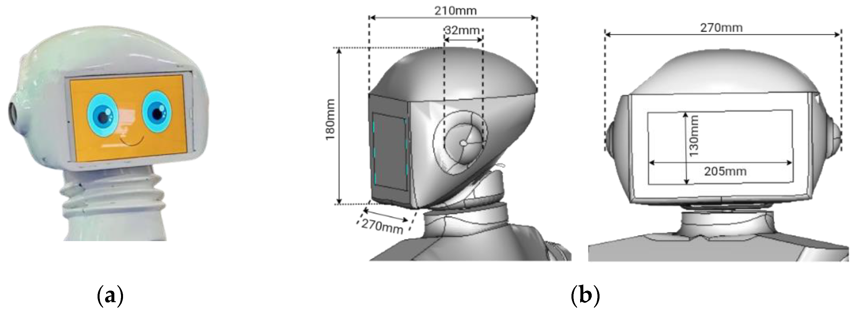
The robot’s head is kept at 180 mm in height, 270 mm in breadth, and 210 mm in length to be equivalent to human dimensions so as to look similar to humans for friendly interaction in a social environment. The front aperture is used to install a tablet (touch screen) which is 130 mm in length and 205 mm in breadth, while the two earholes, each of 32 mm diameter, are used to fix speakers to hear voice of the HCPs during interaction. Figure 2 shows the front and side view of RoboDoc head CAD model.

2.2. Single-DoF Neck Design

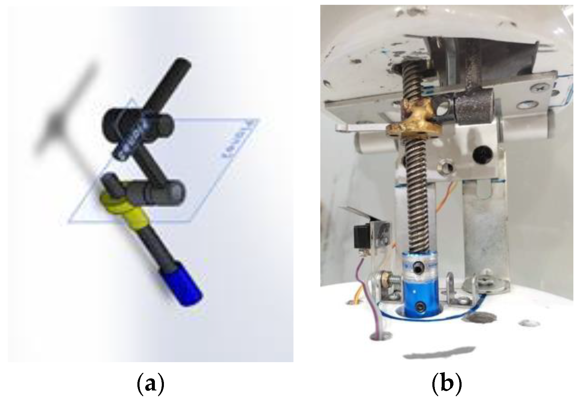
The up and down movement of the RoboDoc neck is performed by a fixed point called fulcrum. This movement is comprised of two mechanisms: one is the lead screw mechanism is coupled to a DC gear motor at one end which further rotates the screw while moving up and down on the lead, forming a linear or prismatic motion. The other mechanism is the cranked shaft mechanism that is used to convert the prismatic motion of the screw to re-revolute movement of the neck. This is done using a link rod coupled with a moveable end of the neck. Twist-to-linear conversion is provided by lead screw and linear to rotary motion is provided by crankshaft (link rod).
Given the head’s weight including tablet and peripherals, a direct motor-based neck control requires a considerably large motor occupying more volume and high energy consumption. Therefore, different mechanisms [39,40] were investigated to control the neck motor with the minimum area and low energy consumption, especially when in a no-movement condition. A novel lead-screw and crankshaft mechanism driven by 12 V 5 rpm DC motor is designed, whose simulation and fabrication is shown in Figure 3 and Figure 4.
Lead screw and crankshaft design for the neck mechanism were formulated using mechanical design via CAD modeling (Figure 3 shows the designed mechanism on SolidWorks software). The left and right rotation of the RoboDoc itself carries out the left and right movement of the neck. Since practically all the patients are seated in front of the robot, there is no specific need for left and right movement of the neck.
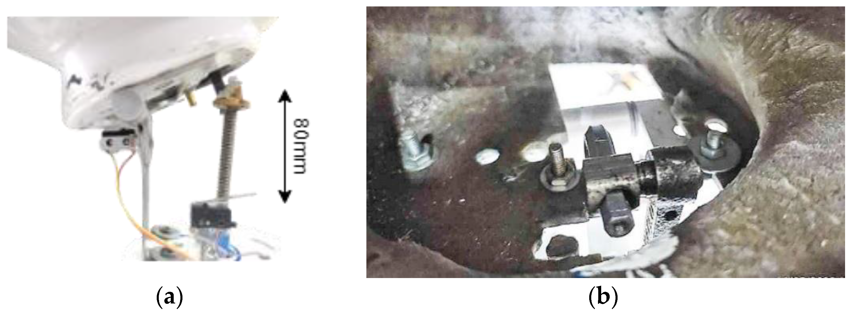
In order to limit the movement of the neck, mechanical limit switches are mounted at the front and rear sides as shown above in Figure 4a. The neck is limited to be raised by 80 mm. Figure 4b shows the link mechanism of neck and head.

2.3. Arm Design and Prototyping

The arms are of 3-DOF anthropomorphic design, where the shoulder joint has single-DOF, the elbow joint has single-DOF, and the end effector of the arm has single-DOF movement. The 3-DOF robotic arm is designed to be lightweight, simple, and cost-effective in construction. Both arms have two revolute joints, one at the shoulder and one at elbow, whereas the end effector of the left arm has a linear actuator to move the chest piece of the e-stethoscope in forward and backward directions. The end effector of the right arm has a servo motor responsible for rotating pulse oximeter and IR temperature thermometer attached on an L-shaped bracket which is mounted on servo motor shaft.
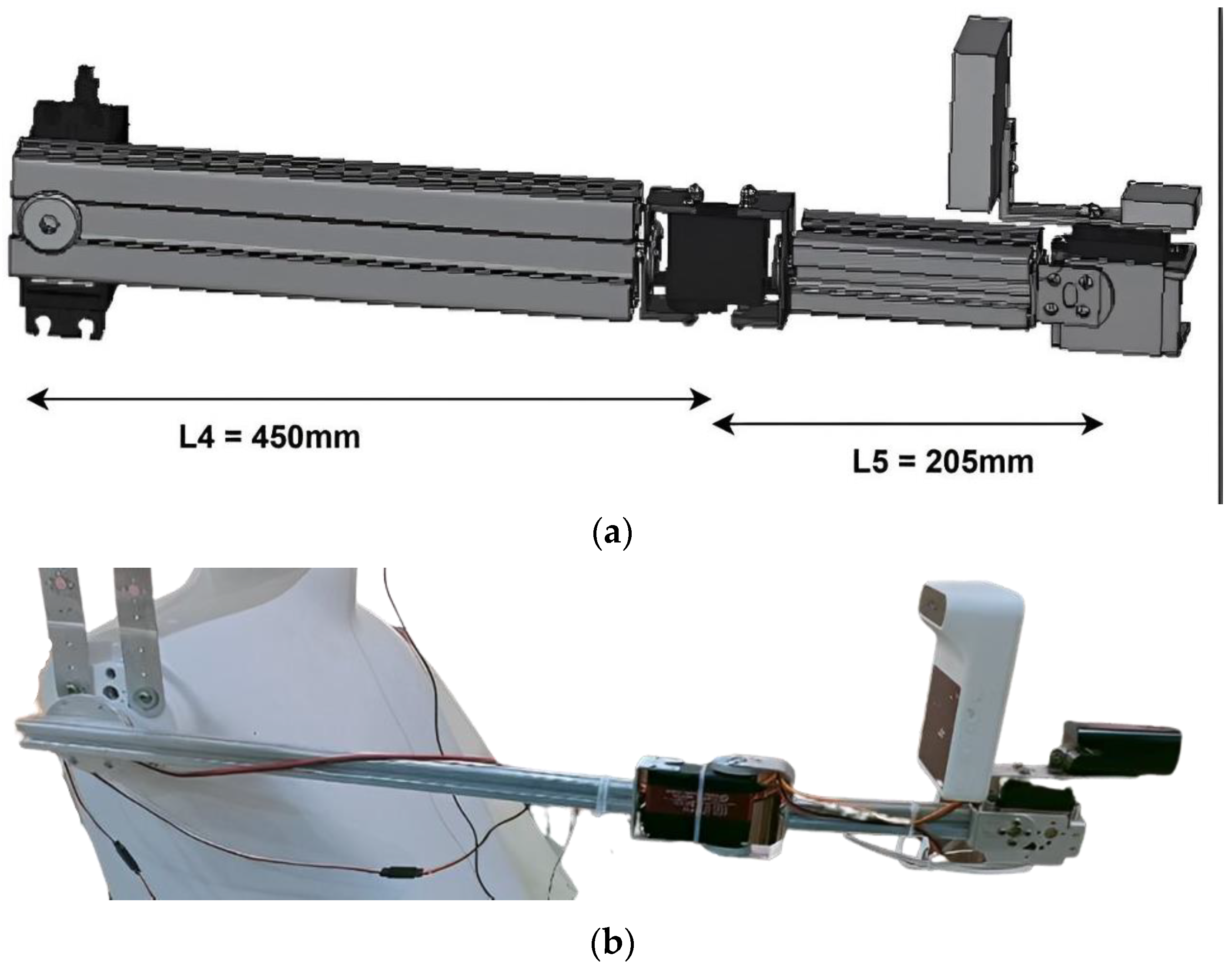
The left arm has three linear dimensions from the shoulder joint, as shown in Figure 5a such that the length from the shoulder joint to the elbow joint is L1 = 430 mm, and the length from the elbow joint to the linear actuator (end-effector) is L2 = 180 mm, i.e., including the fixed length of linear actuator. The linear actuator can have a variable length of 1 mm < L3 < 100 mm whereas the fixed rod length is 140 mm. Figure 5a shows the CAD design of the mechanical structure for the left arm, whereas Figure 5b shows its design implementation. The right arm consists of two joints, and the length of the shoulder to elbow joint is L4 = 450 mm and the length of the elbow joint to end-effector is L5 = 205 mm as shown in Figure 6a. The end-effector of the right arm is an L-shaped bracket to mount IR Temperature taking device and oximeter on each side as shown in Figure 6.
The shoulder joint is controlled using a 12 V, 5 rpm DC motor of high torque while RoboDoc digital servo motors are used at the elbow joints. DC motor’s linear actuator is used for variable length at the end of the left arm. The links used for support are made up of aluminum as it is lightweight. The material used for the outer mold of the arm is fiber glass with a thickness of 3 mm which is suitable for optimal mechanical characteristics. To limit the movement of both the arms, two limit switches are integrated at the front and rear side of each shoulder joint so that the arm can move between 0-to-135-degrees in order to avoid any inappropriate behavior.

2.4. Body Design

The body of RoboDoc is 4.5 ft tall and made up of fiber material using a design mold with an aesthetically pleasing appearance that is shown in Figure 7 below. The shape of the body is designed in such a way to give RoboDoc a humanoid appearance also the height of RoboDoc is considered to facilitate communication with adults. There is a provision on the torso of the RoboDoc where a secondary display or a logo can be placed. A rack is placed in the torso to hold the electronic circuitry of RoboDoc.

2.5. Rover Design

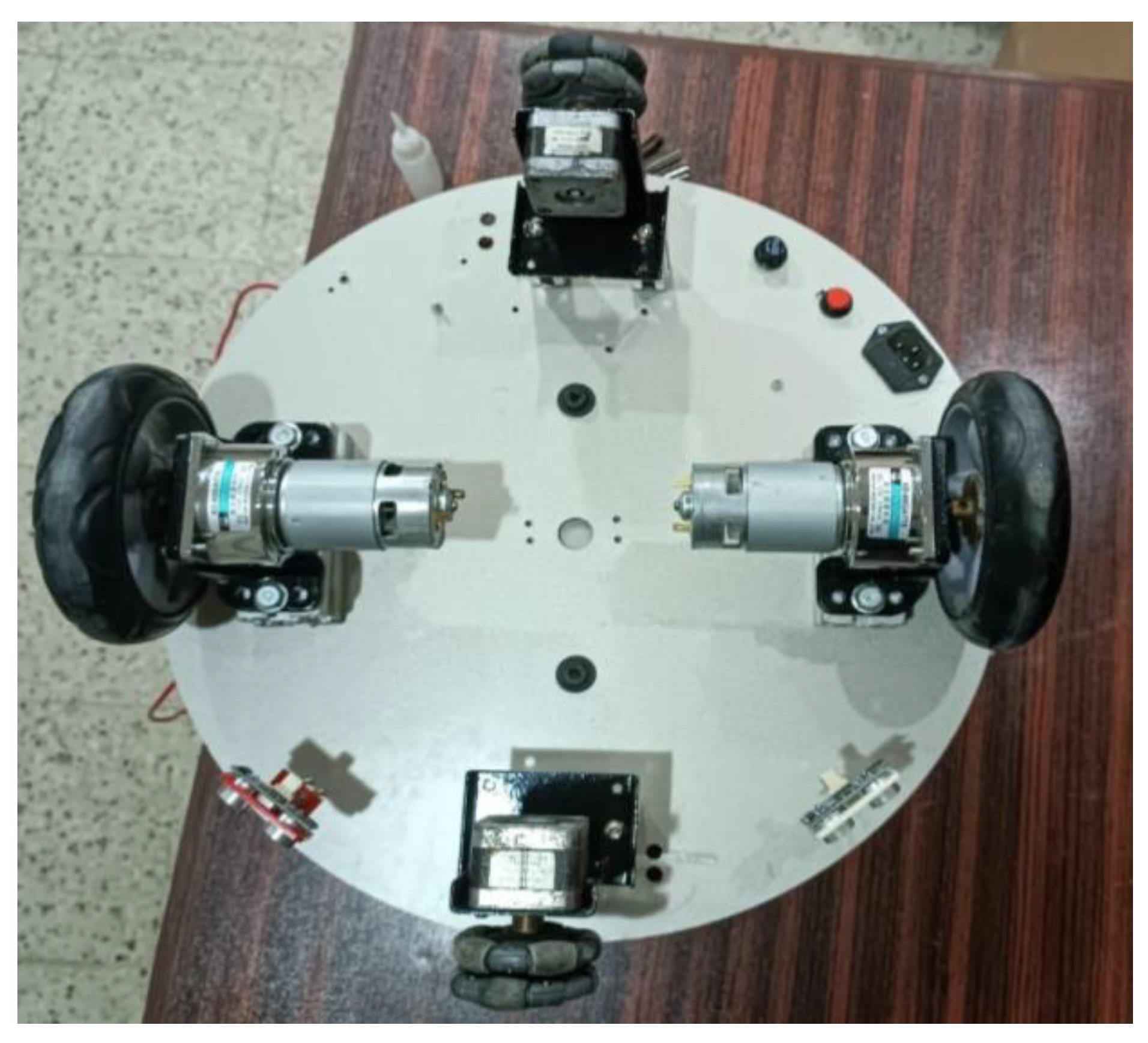
Figure 8 shows the rover design of RoboDoc with diameter of 178 mm made of ACM (aluminum composite material). It has four wheels attached to it; two wheels are coupled with controlled DC geared motors, whereas the other two wheels are omni wheels for the support and RoboDoc’s free motion in any direction. The battery, along with the controlling circuitry, is placed on the rover base due to its considerable weight. To avoid any collisions, two proximity sensors are mounted on the base of RoboDoc; it is a social robot thus this precaution is a necessity with the addition of remote teleoperation control. The popular HC SR 04 ultrasonic proximity sensor has been used, and this sensor has a useful detection range of 30 to 40 cm. The signal from this sensor is interlocked with the drive command to the locomotion motor driver such that the locomotion of the robot does not take place when an object is detected in its proximity.

3. Electrical and Electronic Design

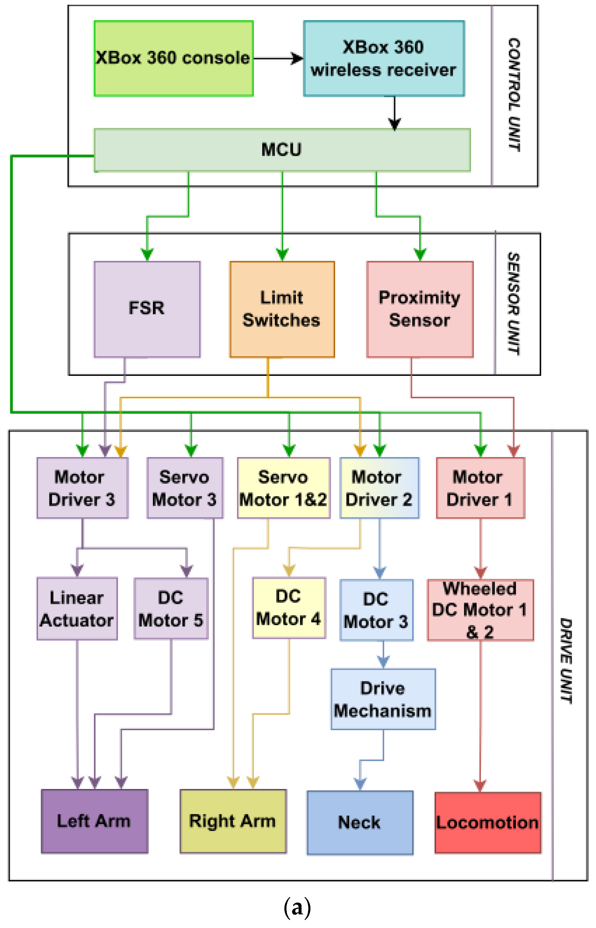
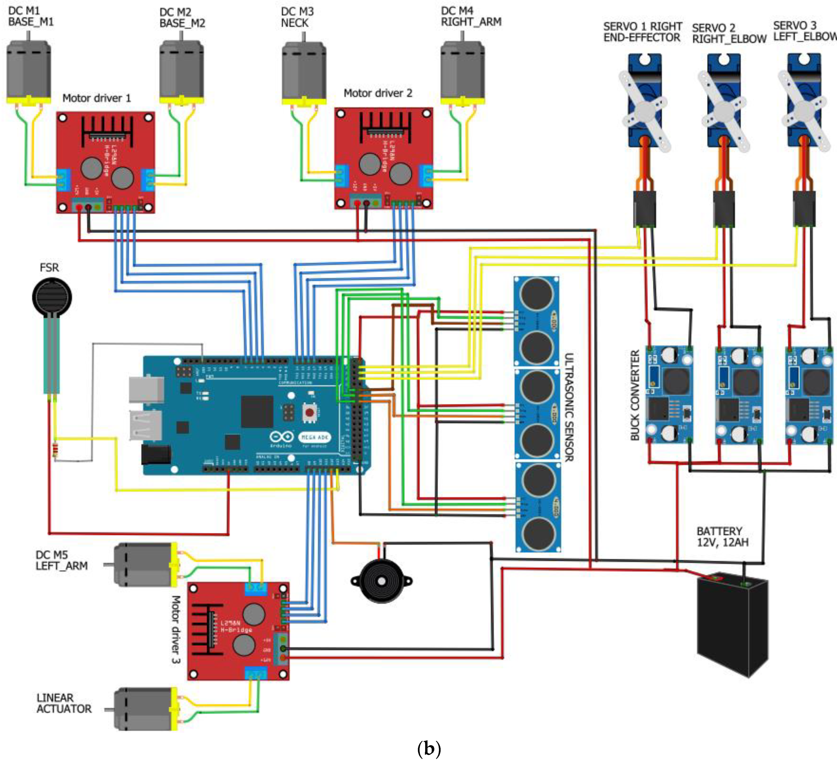
Three units make up the electronic control circuitry: the control unit, the sensor unit, and the drive unit. Figure 9a displays the block diagram for each of the three parts as well as the connections between them, which are further explained in the subsequent sections. A detailed diagram for all the connections between electrical modules, motors, and sensors is shown in Figure 9b.

3.1. Control Unit

The control unit consists of an Xbox 360 controller that serves as both a master and a slave, which communicates commands to and from an Arduino mega 2560. The Xbox receiver delivers and receives commands through a USB host shield to the Arduino’s SPI control pins as shown in Figure 10.
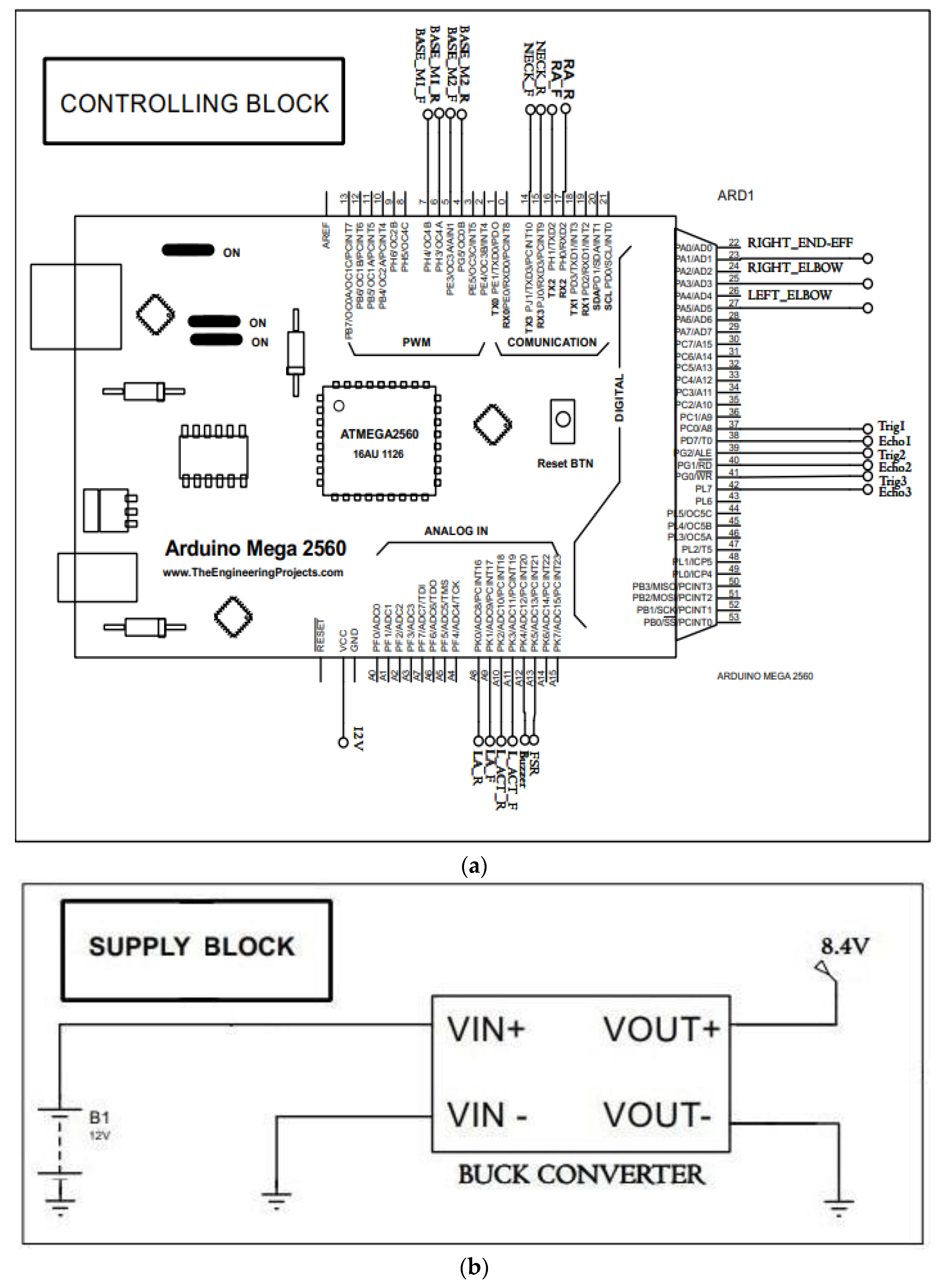
Figure 11a displays the schematic for the aforementioned device to the main control unit, i.e., Arduino Mega 2560. Proteus 8.9 is used in the design of the electrical circuit. This diagram depicts how all of the modules discussed above are electrically connected to one another. The lead acid battery in the power supply block is rated at 12 V 12 Ah, and it is connected to an LM2596 DC-DC converter to decrease the voltage level for the servo motors in the motor unit as shown in Figure 11b.

3.2. Sensing Unit

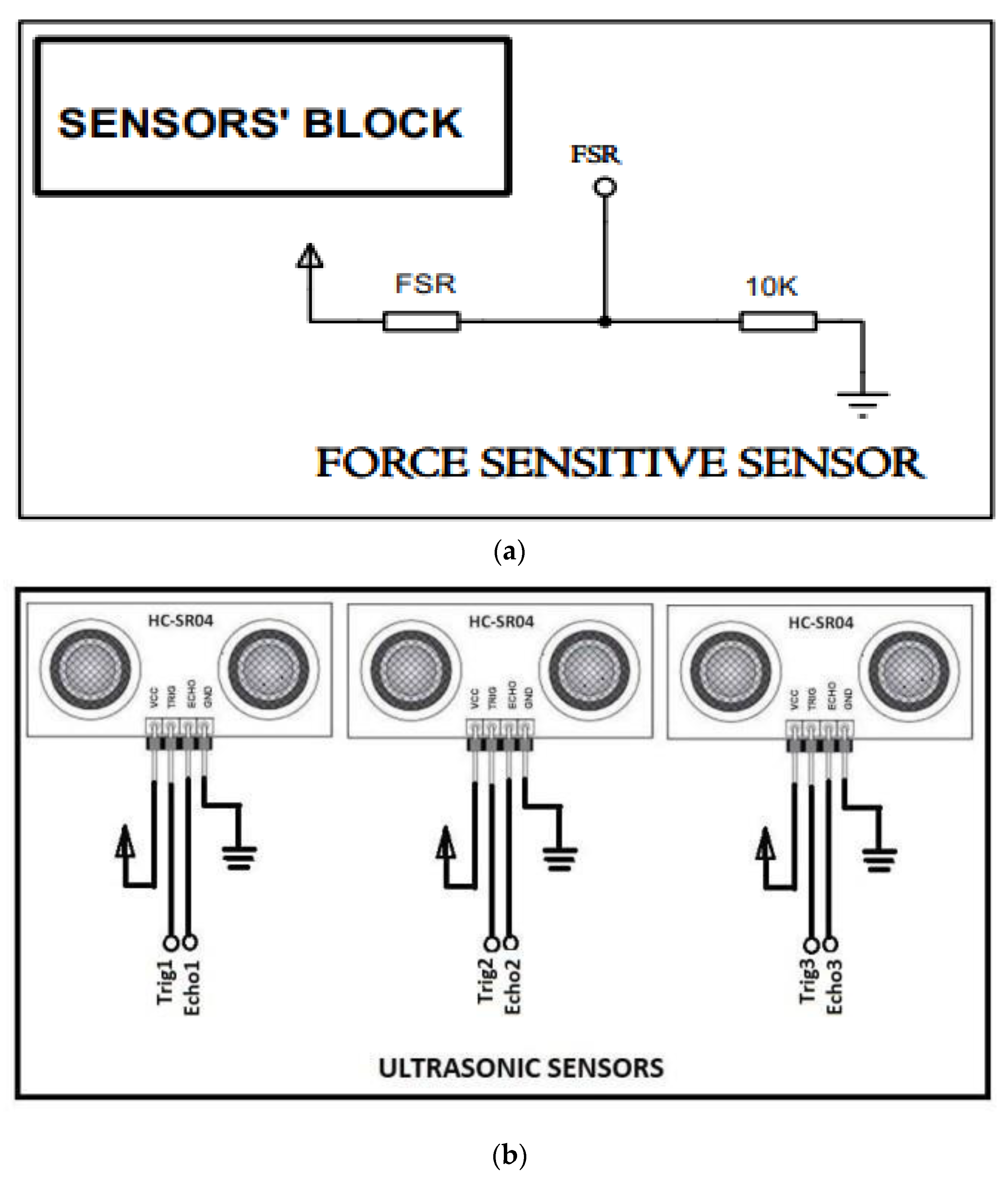
The Sensing Unit has proximity sensors to avoid any collision as these sensors are linked with the base drivers to run (on) and stop (off) the RoboDoc. The mechanical limit switches are connected to the arms and neck to restrict movement and prevent abnormal movement as the RoboDoc is required to work with humans. The limit switches are set up to operate ‘normally closed’. When the switches are pressed, the motor’s power is immediately shut off, and the arms along with neck immediately stop moving. Additionally, an FSR (Force Sensing Resistor) is mounted on the rear of the e-stethoscope chest piece. When it makes contact with the patient’s chest, the force is detected at the surface area of the sensor and the HCP receives a sensory signal via vibrations on the Xbox 360 controller. Based on that, HCP stops moving the arm further.
Additionally, it is found that when the e-steth is applied at a specific pressure to the patient’s chest, it produces less noise and yields reliable auscultation results. As a result, there are different levels of sensory feedback obtained in such a way that if the chest piece is in contact with the patient’s chest, the doctor may feel a periodic vibration of lower intensity. However, if the pressure applied is appropriate and is not harming the patient, the vibrations becomes stronger and serve as a warning to the doctor to stop moving the e-steth any further. As a result, the FSR essentially sends a signal to the Xbox controller’s primary controller, activating vibrations that alert the doctor to halt the specific actuator. Figure 12 depicts the electrical linkage between the primary controller and the sensors.

3.3. Driver Unit

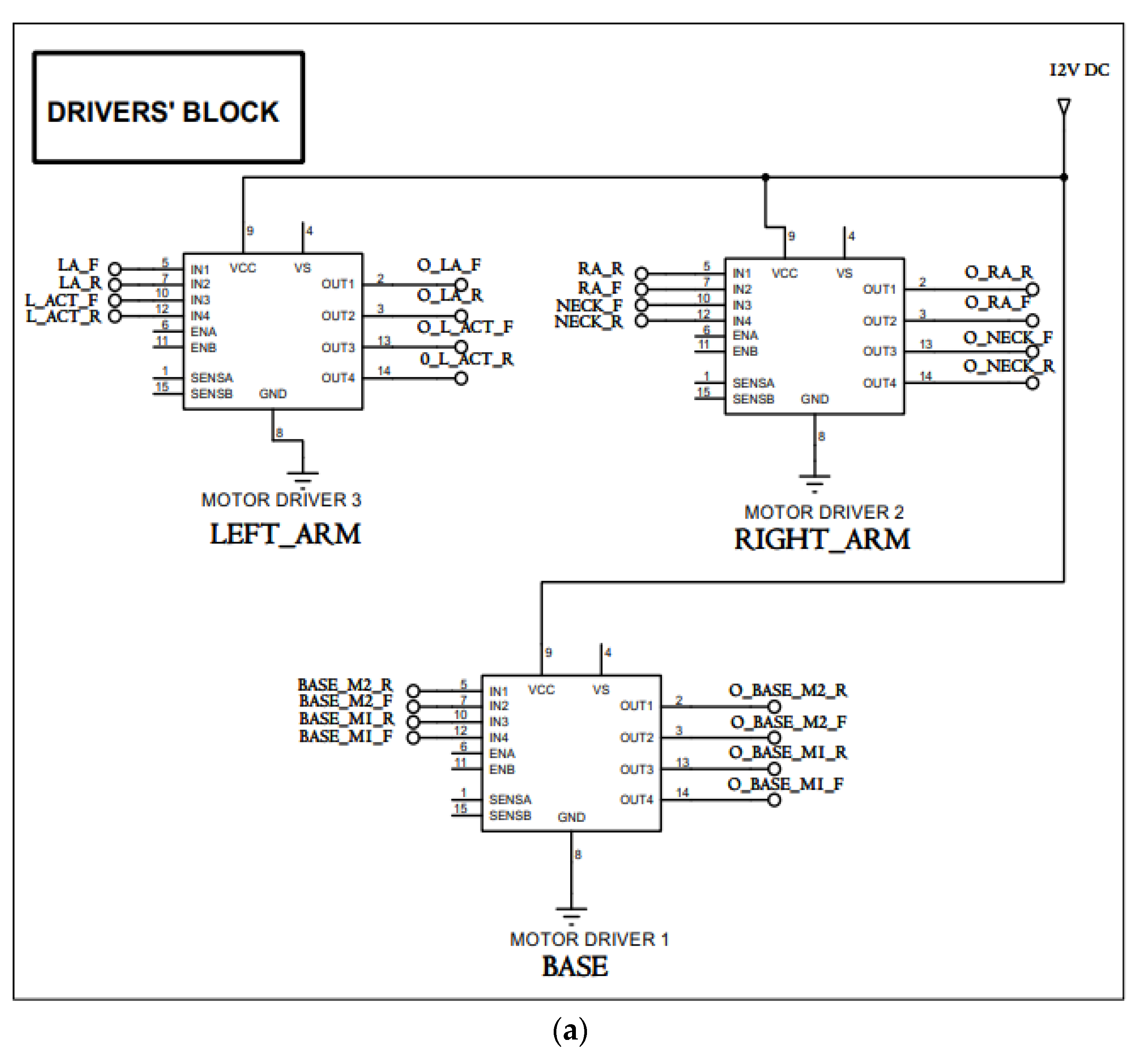
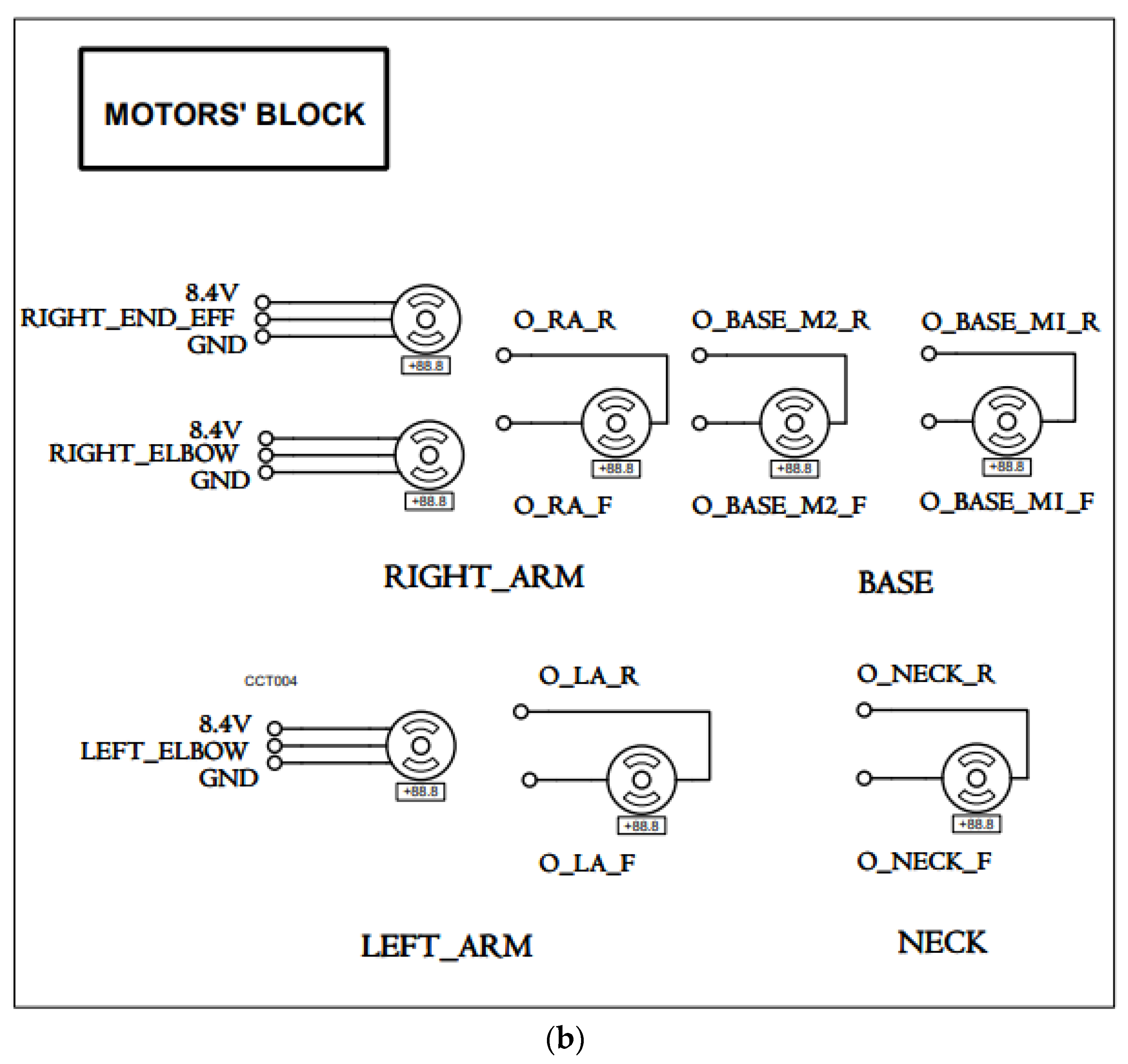
As soon as the L298N motor drivers get signals from the control unit, they turn on the required actuator responsible for locomotion, neck movement, and arm motions. The control circuitry first assesses the status of respective sensor and then gives command to driver circuitry to move the motor. There are five DC motors altogether, one linear actuator (also a DC motor), and three servo motors. Motor driver 1 is in charge of managing DC motors 1 and 2, which help the robot move, while motor driver 2 is in charge of managing DC motors 3 and 4, which are connected to the neck mechanism and the right arm shoulder, respectively as shown in Figure 13a,b. The elbow of the right arm houses servo motor 2 and the end effectors, such as the IR thermometer and pulse oximeter, are connected to servo motor 1. The elbow of the left arm is connected to servo motor 3. Motor driver 3 operates to drive the DC motor 5 attached to left arm’s shoulder. The linear actuator is attached with the e-steth to achieve forward (towards patient’s chest) and backward (away from patient’s chest) motion. The characteristics of the electronic components utilized in RoboDoc are displayed in Table 2.

4. Interfacing of Vital Taking Devices

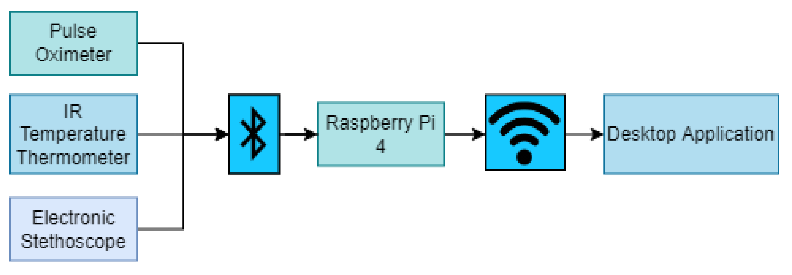
A pulse oximeter, an electronic stethoscope known as a “e-steth”, and an IR-based temperature thermometer have all been added to RoboDoc so that it may collect important vitals from patients using its calibration. The FDA certification is taken into consideration when choosing these essential measuring tools so that healthcare professionals may be confident in the readings and data that they are gathering for such a delicate profession. The right arm of RoboDoc is mounted with the IR temperature thermometer and pulse oximeter while the left arm is integrated with the e-stethoscope. A top-notch digital stethoscope, the e-steth [41], offers doctors and nurses clear heart and lung sounds for improved diagnosis. It is an affordable solution for hospitals and basic healthcare facilities. It is possible to transmit sounds to a remote site during Teleconsultation since the data transfer technique is wireless, i.e., through Bluetooth interfacing. These gadgets are linked to the Raspberry Pi 4 using the BluetoothBluetooth protocol, and the Raspberry Pi communicates with the HCP remote server using WiFi.
The pulse oximeter [42] provides data on the heart rate, oxygen saturation, perfusion index, and any irregularities in the pulse. The IR temperature thermometer [43], used to monitor body temperature is the third gadget, which also uses a Bluetooth transmission protocol. These devices are mounted on a RoboDoc so that the doctor can monitor the patient’s vital signs remotely while staying in another room. To activate the devices, the doctor must click on the desktop application’s virtual buttons, which cause the Raspberry Pi to begin sending readings. If the doctor wants to record the readings, he must click on the record button. These devices were chosen keeping the COVID-19 pandemic and all the vital signs required by the doctor for examining a patient in mind. All the data is logged and sent to a desktop application for live monitoring via Raspberry pi 4 over WiFi as shown in Figure 14.

5. Haptics Feedback Interface Design for Stethoscope

Haptics means the use of technology to the senses of touch and motion, especially to replicate on a computer or by remote control the emotions that a user might feel while interacting with real-world objects [44].
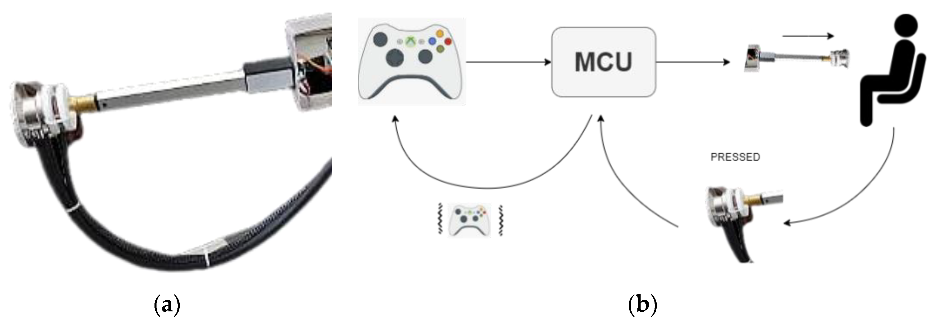
By the use of haptics, the mechanism of heart-rate may be devised. In this regard, the chest piece of e-steth is attached to the end of a moveable rod of linear actuator as shown in Figure 15. When the doctor needs to hear the auscultations of heart or lungs of the patient, they can just signal the primary controller by pressing a button (responsible for moving linear actuator) on the Xbox 360 controller. Since the RoboDoc is teleoperated, motors are commanded to move forward/backward. The main challenge is that how to know that the chest piece of the e-steth is on a patient’s chest for that sensory feedback through an Xbox controller. A Force Sensing Resistor (FSR) is placed at the back of the e-steth when a force is applied that signals the primary controller, i.e., that it is in contact with a surface that furthers give signal to Xbox controller and it activates the vibratory motor periodically and the HCP feels less intense vibrations knowing that now the chest piece is in contact with the patient. To hear clear auscultations, a minimal pressure applied by the e-steth chest piece to the patient’s chest is found helpful. To avoid putting any excess pressure on the patient’s chest, a threshold for pressure is set and exceeding that pressure limit makes the Xbox vibrate strongly in order to alert the doctor that he needs to stop the actuator. In addition, an audible aid is also provided using the speaker.
In this RoboDoc design, we are just focusing on taking the Coronavirus (COVID-19) patients’ vitals via RoboDoc’s wireless control to avoid putting lives of HCPs in danger of catching the virus. To the best of the authors’ knowledge, wireless/IoT technologies have helped the isolated patients without any reported harms to the COVID-19 patients. Further, the limitation of Bluetooth and Wi-Fi connectivity for medical applications stems from the fact that these standards do not guarantee QoS at all times. Hence, they are not suitable for continuous monitoring and/or mission critical situations. In contrast, since the Bluetooth and Wi-Fi in the RoboDoc scenario are used for teleoperation while the healthcare worker is present, there are no similar risks involved. In the future, further research may be performed on the limitation of wireless/Bluetooth-run devices’ impact on the COVID affected patients [45,46].

6. Interactive Graphical User Interface

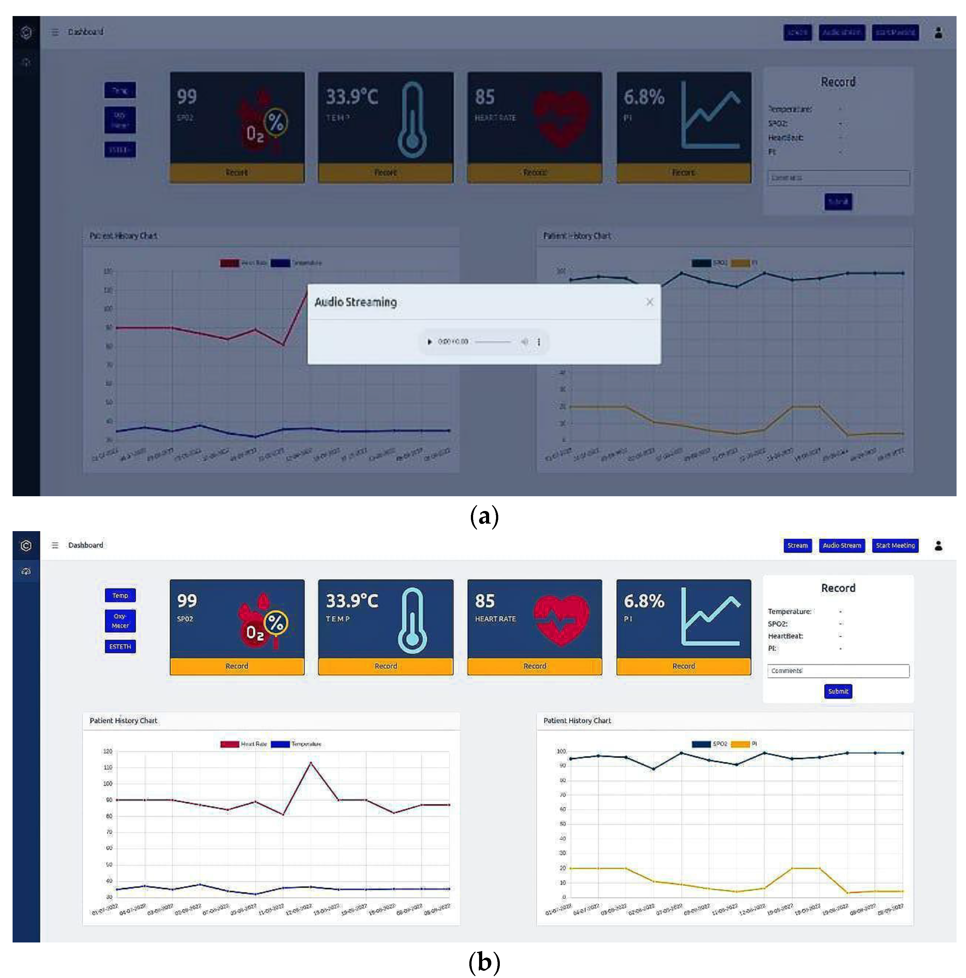
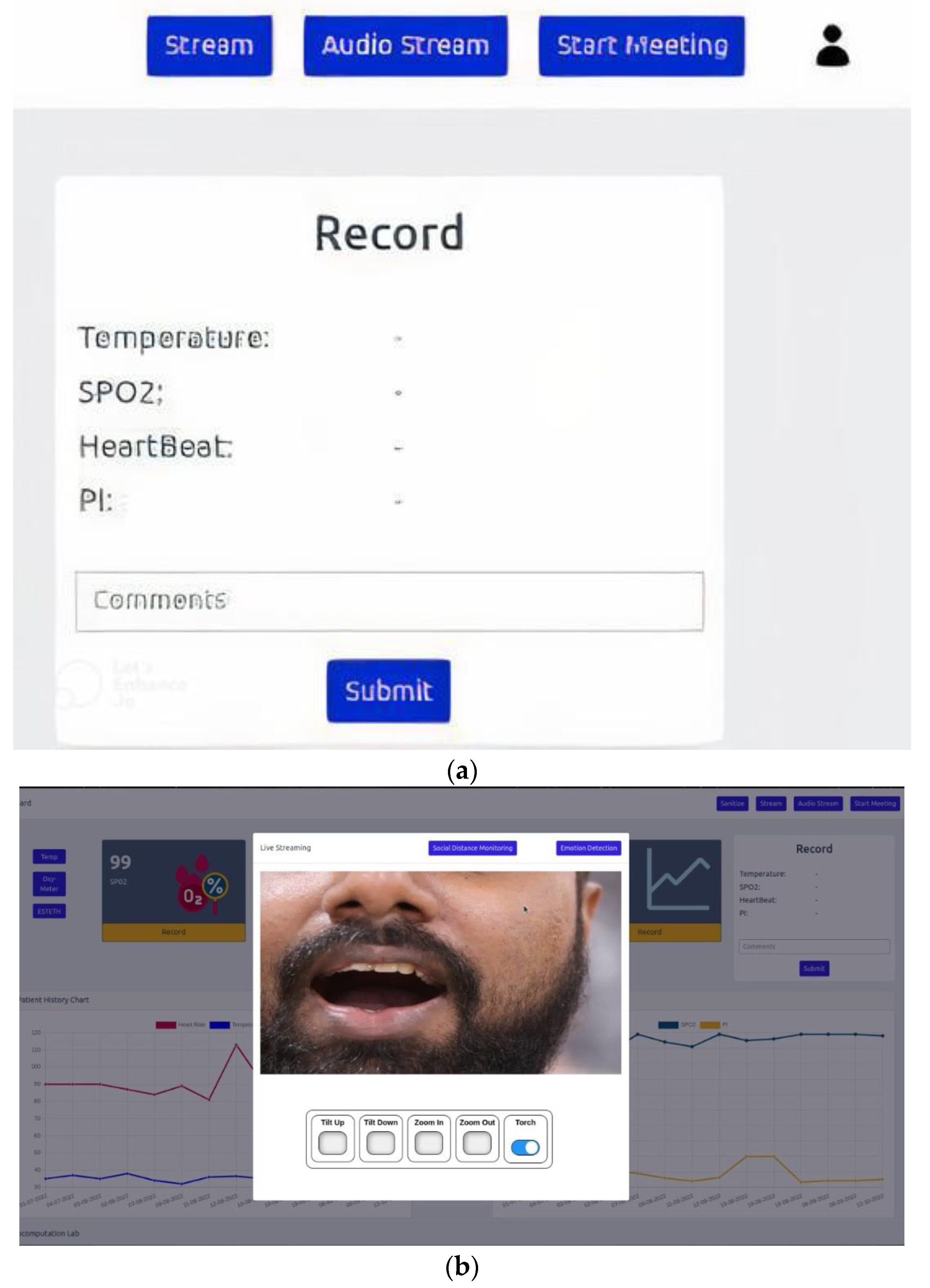
Since RoboDoc is a teleoperated medical robot, the doctor is given a desktop server with a dashboard (shown in Figure 16b) to interact with patients. From this server, the doctor can wirelessly access data from devices such as a pulse oximeter, an infrared thermometer, and an e-steth. The doctor presses the virtual buttons provided at the left corner of the screen as indicated in Figure 16b to activate the vital-taking devices. Additionally, using the virtual stream button as shown in Figure 17a, the doctor is able to access the live video streaming of the DSLR camera that is mounted on RoboDoc’s shoulder. As soon as the doctor presses the virtual stream button, a popup window displaying the live stream is open. The dashboard also includes a part where the doctor may enter a patient new record and view existing data using the patient’s given MR (medical record) number.
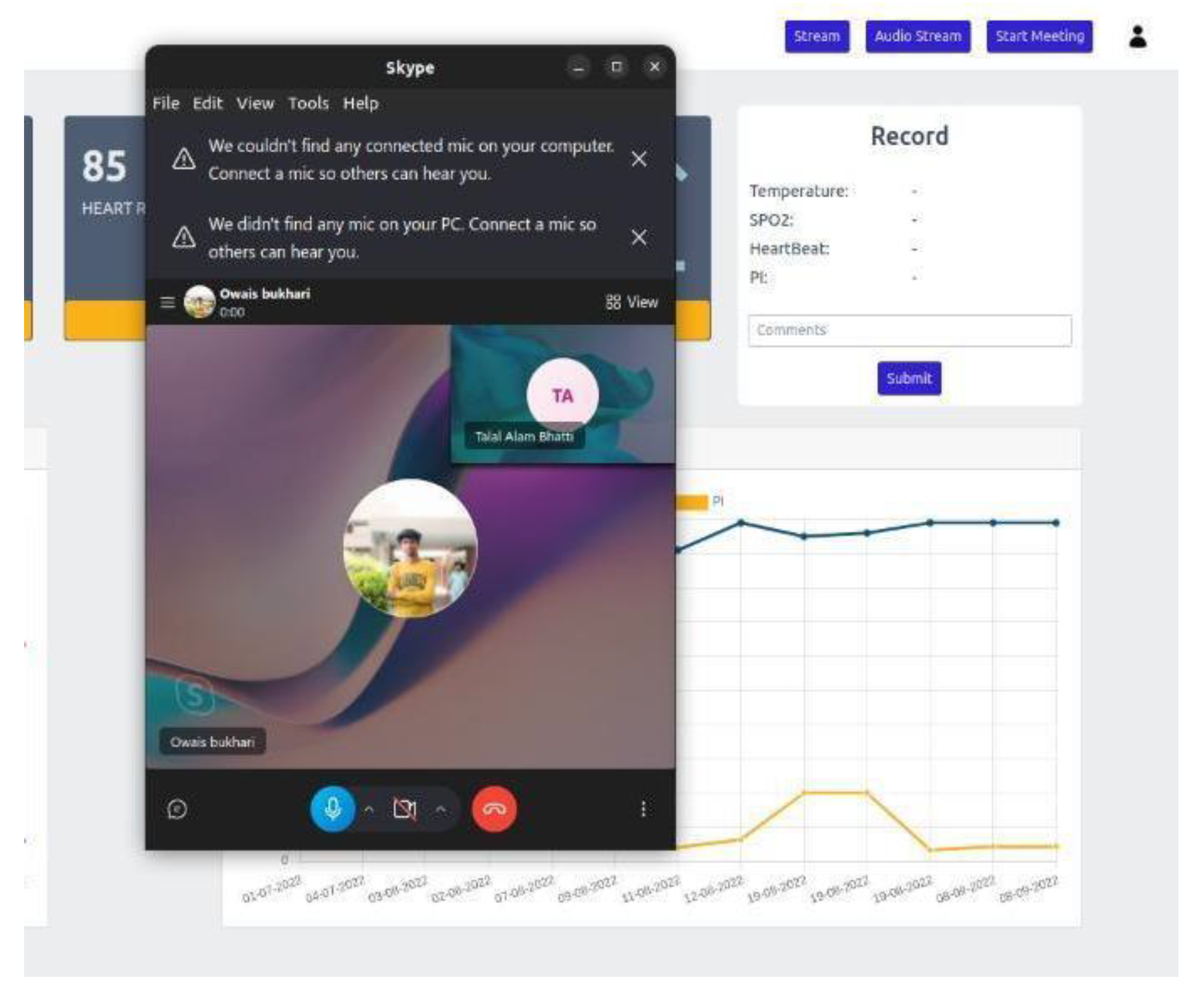
In order to have an interactive session between the HCP and the patient, there is also the option to have a live video chat through Skype call using the RoboDoc Tablet interface. This may be started by clicking the “Start meeting” button as shown at the top right corner of Figure 18.
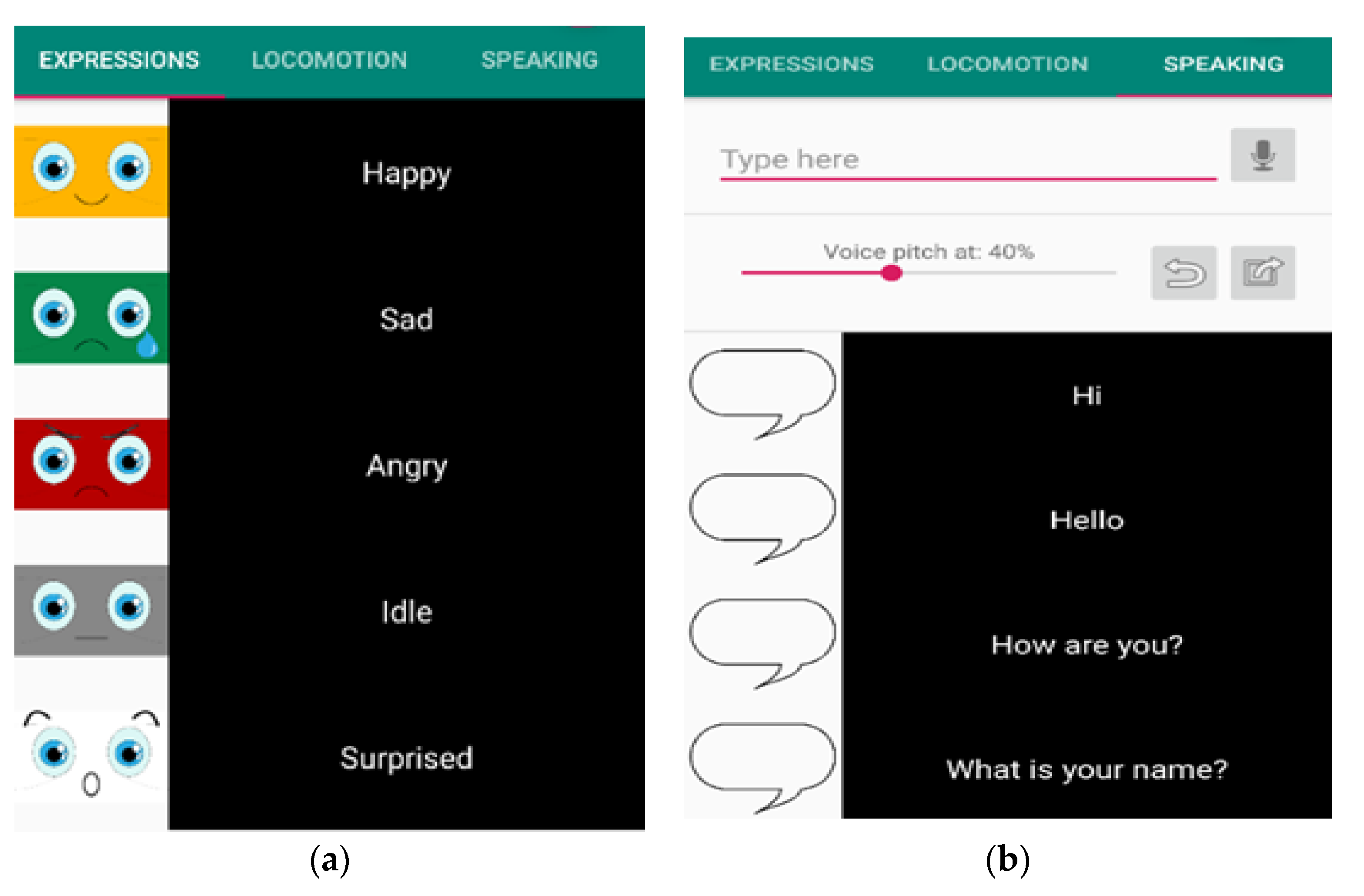
Additionally, the tablet GUI that interacts with patients is controlled by a mobile app shown in Figure 19. However, the RoboDoc face is controlled by doctor or other medical personnel. The cell phone operating the robot face and the tablet mounted on the RoboDoc face are connected through a Bluetooth interface. RoboDoc’s expressions can be controlled easily. Additionally, text to voice functionality on mobile devices allows us to write text and then hit the mic-button to have RoboDoc speak the written text.

7. DSLR Camera Interface

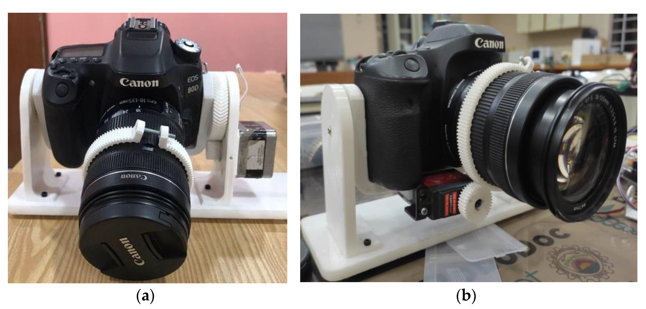
RoboDoc is also capable of viewing the patient’s throat. The doctor may be able to remotely inspect the throat conditions via visual aid provided by a high resolution DSLR Camera. The DSLR Camera has been mounted on a frame made of fiber and installed on RoboDoc’s shoulder. As RoboDoc is being operated remotely, the camera is also required to be controlled remotely to get a clear view of throat. For achieving this purpose, two mechanisms have been introduced, namely: (1) Zoom Mechanism and (2) Tilt Mechanism. The tilt mechanism has been controlled by a DC gear motor, whereas the zoom mechanism has been controlled by a servo motor as shown in Figure 20.
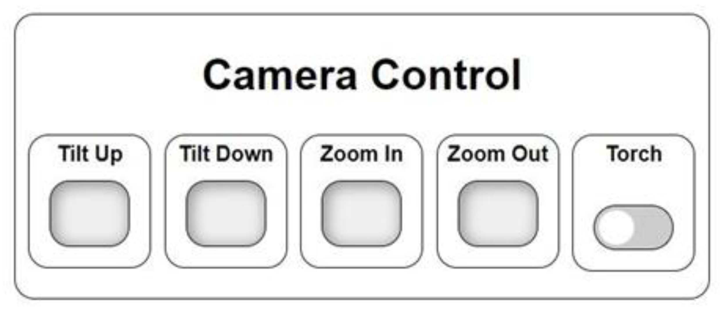
The tilt and zoom mechanisms have been interfaced using Web Socket through Raspberry Pi webserver as shown in Figure 21. The HCP may be able to tilt the camera up or down and zoom in or out by pressing the respective buttons in order to locate and get a clear view of patient’s throat. A flashlight has also been provided so that the doctor can get a good look inside the patient’s mouth. In addition to tilt and zoom from the web-based control, the panning of camera is attained by rotating the robot on its axis. Furthermore, for RoboDoc to have a clear view of a remote patient’s throat, the patients can be instructed by the HCP to adjust according to the camera.

8. Complete Overview of Robodoc

The proposed RoboDoc, a social healthcare teleoperated robot, can capture all the fundamental vital signs, digitally engage with patients through video, inspect a patient’s throat using an HD camera, and record all the data remotely.
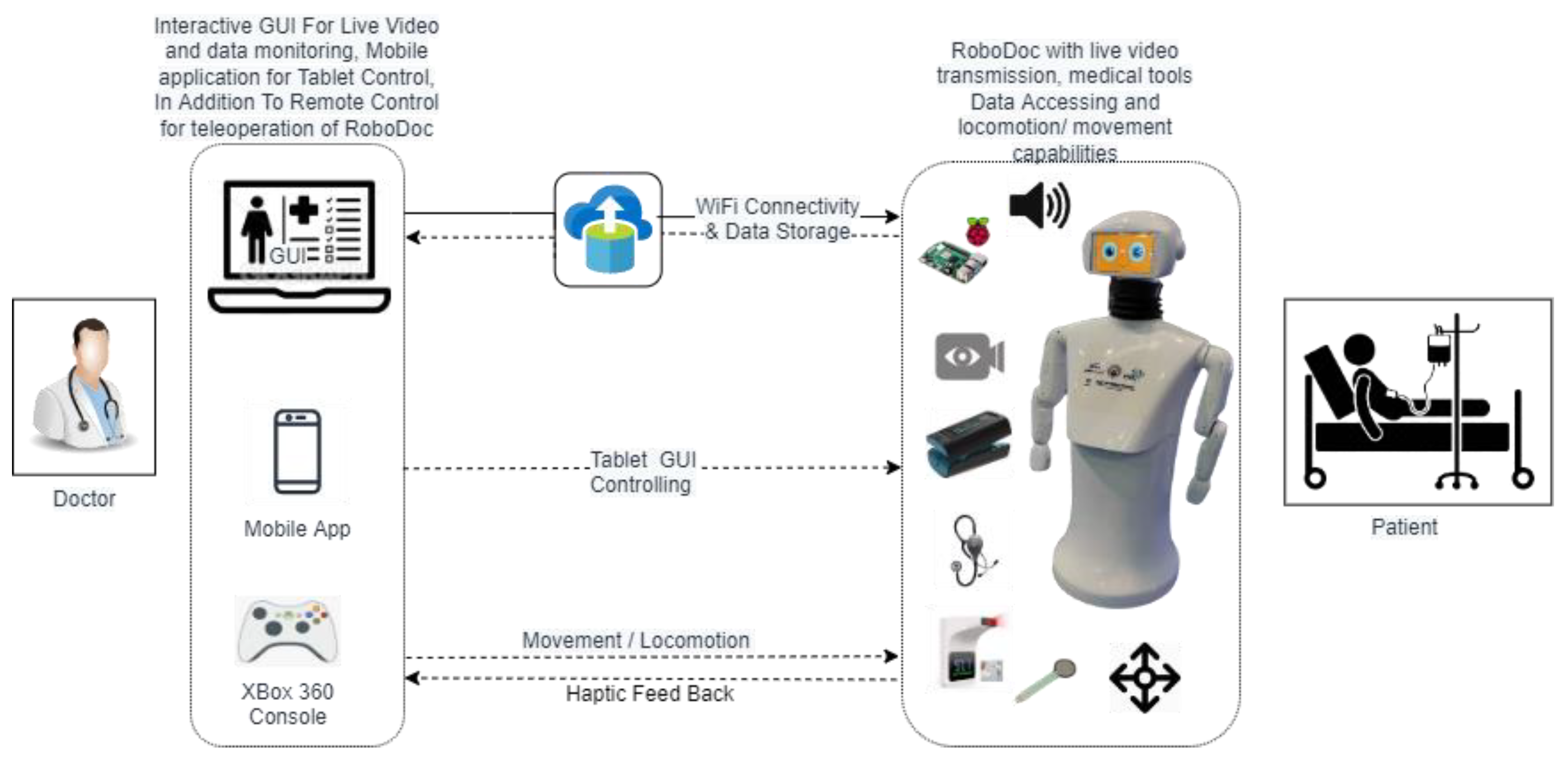
As depicted in Figure 22, the human doctor can control arm and robot movements using Xbox 360 controller, the mobile app can control robot’s face expressions, and the doctor can give commands to patients using text to speech technology. The desktop application handles the camera control, vital monitoring, and video streaming.
There are some safety and precautions added in the design of RoboDoc that are shown in Table 3.

9. Vital Experiment Results

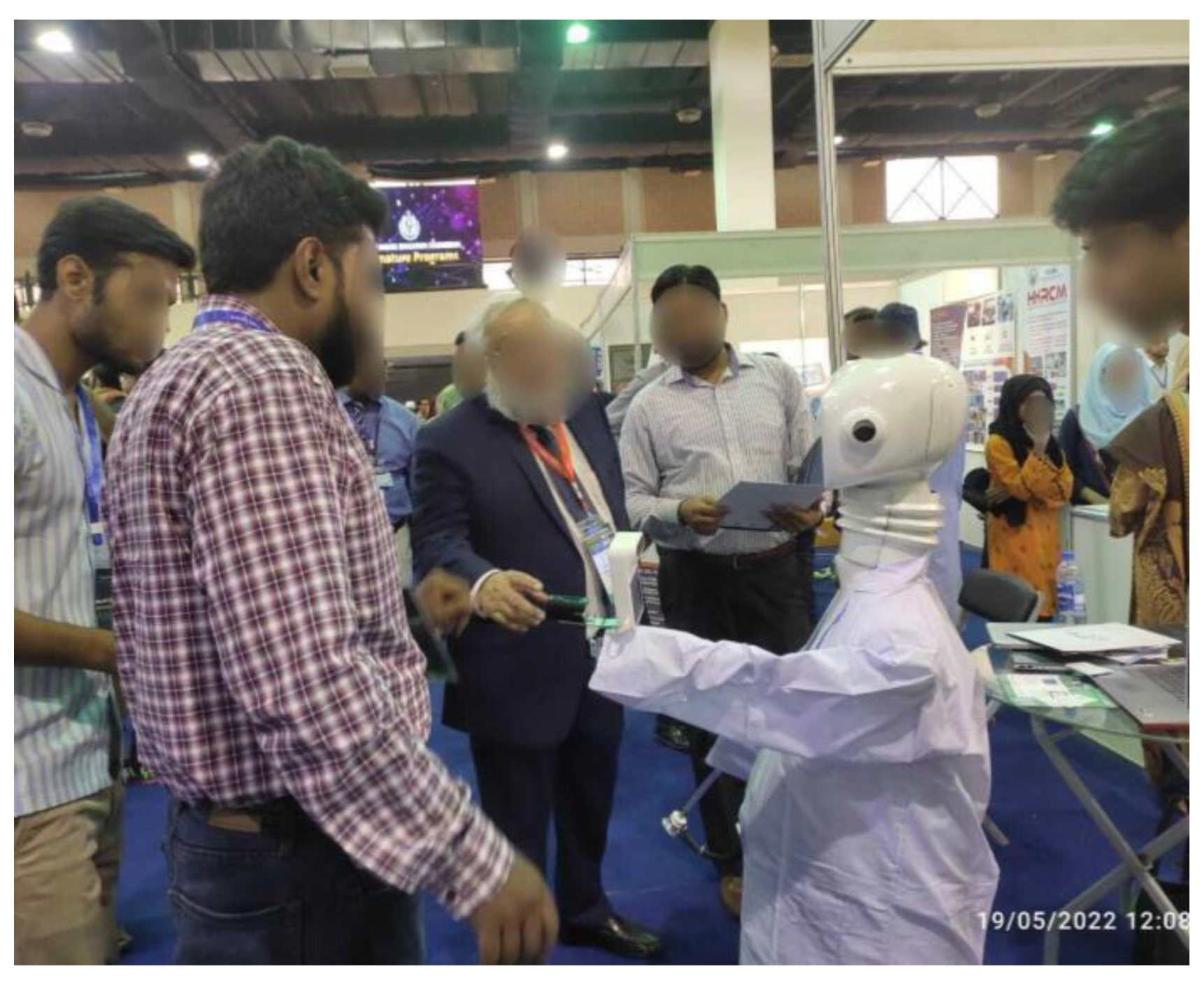
We showcased RoboDoc at a crowded place to see how people interact with it and the results have been amazing, the people have been overwhelming and very comfortable with RoboDoc as shown in Figure 23.

9.1. Stethoscope Haptic Feedback

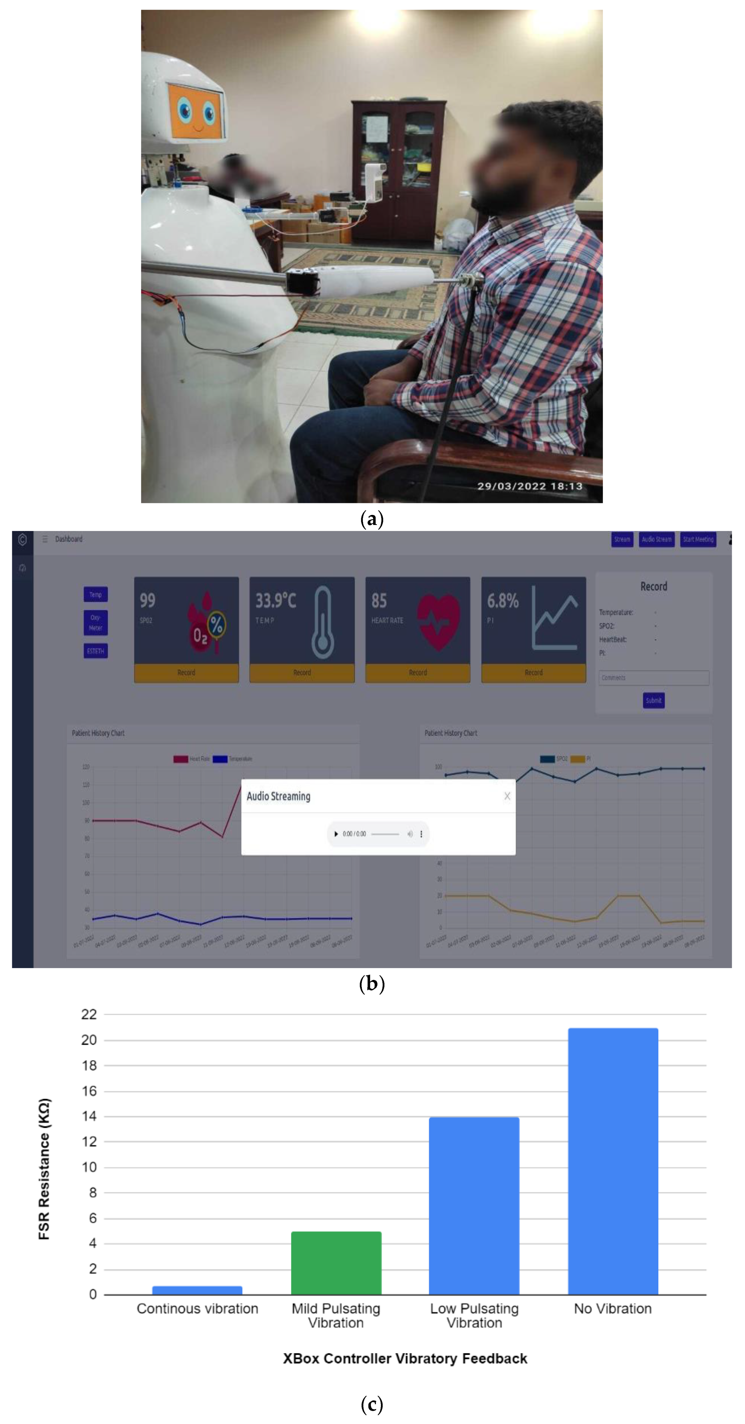
By pushing a chest piece of an e-steth attached to the end of left arm, over the patient’s chest as shown in Figure 24a. The doctor presses the virtual button “ESTETH” at the left side of desktop app as shown in Figure 24b, which pops up an audio streaming player after pressing the play button the doctor can listen to the auscultations on remote site at his computer. When placing the e-steth at the right place on patient’s chest, some thresholds are set for the force applied on patient’s chest. This is done by using a FSR to keep track of force being applied. When the robot exceeds a certain force, in our case an analogue signal of 900, the buzzer can beep and Xbox Controller starts vibrating, indicating the HCP not ot command the arm further forward otherwise it might hurt the patient. This haptic feedback helps us to avoid any harm to the patient.
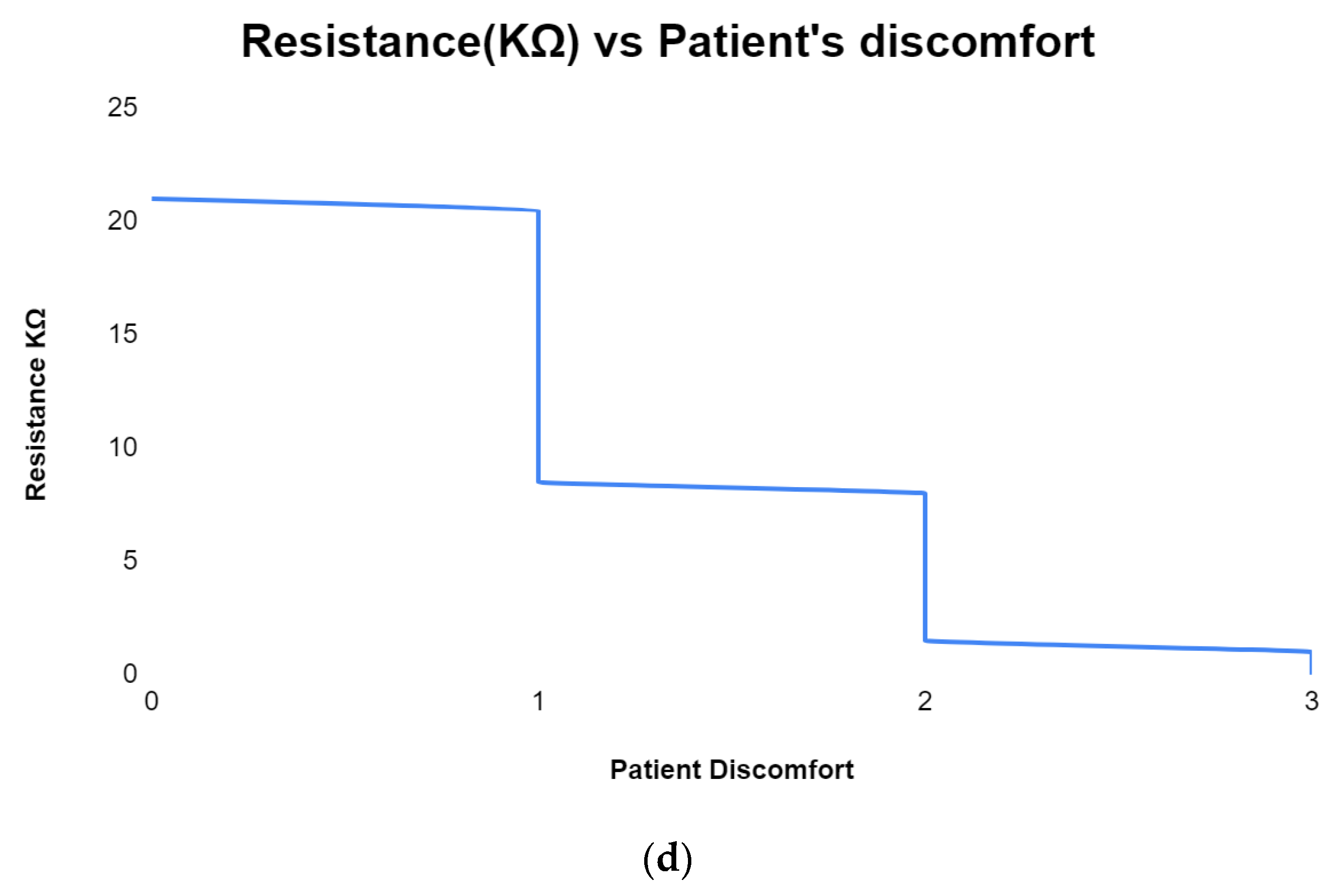
The movement of linear actuator with the e-steth mounted in the front is controlled via the feedback implemented through FSR sensor and vibration actuator of the x-box controller. The FSR sensitivity is correlated with the sound quality of the e-steth to modulate the vibration frequency of the x-box controller such that the vibration of the Xbox controller increases with the decrease in FSR resistance resulting from the pressing of e-steth when the linear actuator is extended pushing the e-steth against the patient. In this regard, an experiment of haptic feedback (vibratory feedback via Xbox Controller) vs. FSR Resistance is performed to establish a relationship between e-steth auscultation and vibratory feedback to the user as shown in Figure 24c. The less FSR resistance means continuous vibration means more e-steth auscultation and vice versa. Similarly, the more vibration means more discomfort on the patient. The range of FSR resistance corresponding to the comfort level of the patient against the push and the clarity of the auscultation from the e-steth are presented in Figure 24d and Table 4.

9.2. Wireless Temperature

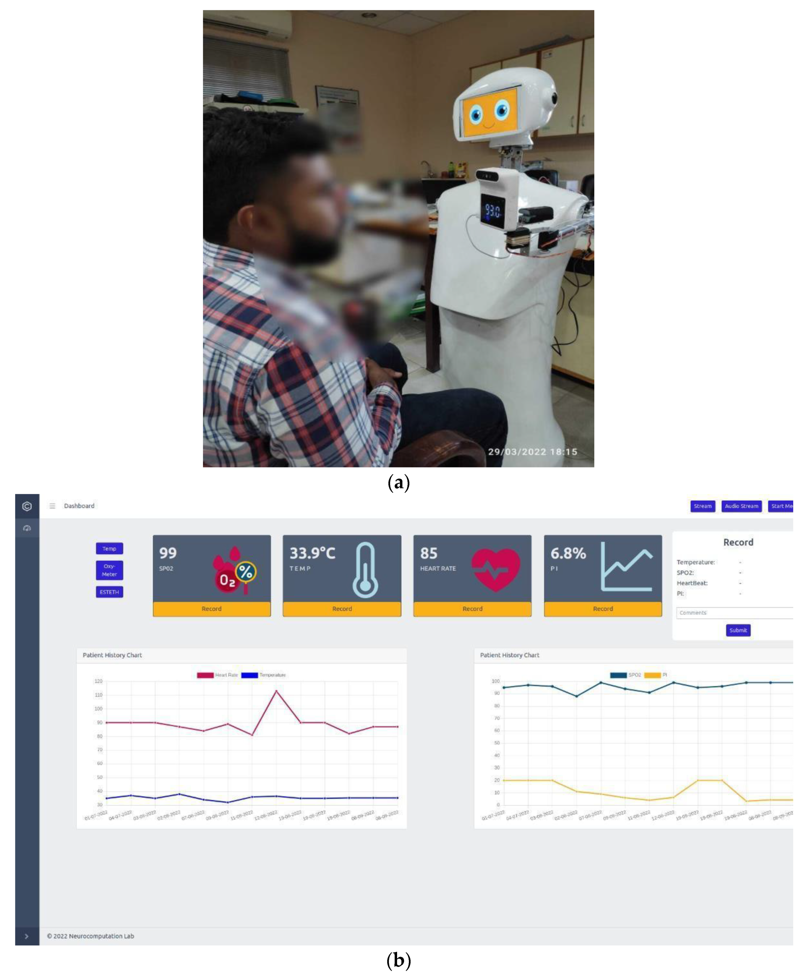
The temperature of the patient is recorded using a smart infrared forehead temperature sensor. which is mounted to the RoboDoc’s right arm. To record the temperature of patient first, the doctor can bring the temperature sensor just in front of patient’s forehead (shown in Figure 25a) by giving commands to the right arm using the Xbox controller. After that, the doctor can press the virtual button “Temp” at the left corner of dashboard of RoboDoc desktop app that can be seen in Figure 25b and it can update the temperature of patient on the screen.

9.3. Pulse Oximeter

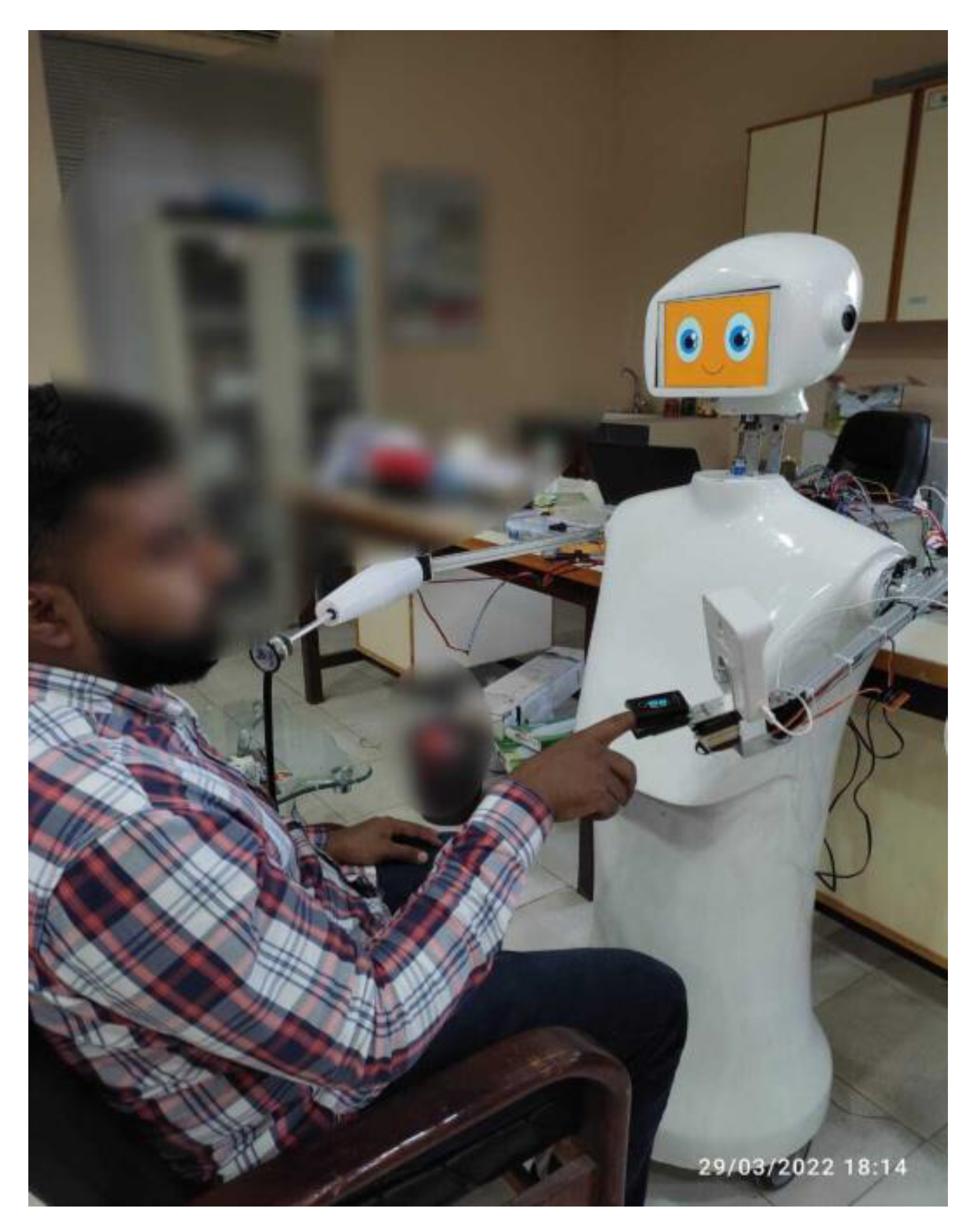
The right arm of RoboDoc is mounted with a Bluetooth pulse oximeter. The RoboDoc is moved parallel to the subject’s hand and a verbal command by the HCP (through the tablet interface of RoboDoc) is issued instructing the patient to insert the finger into the oximeter clipper device as demonstrated in Figure 26. The doctor can then press the Virtual button “Oxy-meter” that can be seen in Figure 25b that can start displaying the pulse rate and oxygen level of the patient on the desktop application.

10. Conclusions

Remote doctor interaction via newly customized designed RoboDoc was successfully tested in a pandemic kind environment for taking basic vitals of contagious patent. RoboDoc is able to take successful readings of pulse oximeter, IR temperature, and e-steth from the remote patient and send all the important data of patient’s vitals. The live streaming of the patient is sent to the doctor, showing real conditions in real time from the patient side. Monitoring results of basic vitals show comfortable interaction of HCP dealing with a patient remotely by the proposed smart RoboDoc. In future, more complex tasks can be added using m-DOF haptic devices and more controls can be used to add time-delayed telepresence [47,48] for long distance patient and doctor interactions for remote and minimal invasive surgeries, etc. [49]. In addition, work on taking ECG signals will also be incorporated [50].

Author Contributions

Conceptualization, H.R.K. and R.U.; Methodology, R.U.; Software, I.H.; Resources, H.R.K.; Data curation, I.H.; Writing—original draft, I.H. and R.U.; Writing—review and editing, H.R.K.; Visualization, R.U.; Supervision, R.U.; Project administration, H.R.K.; Funding acquisition, H.R.K. All authors have read and agreed to the published version of the manuscript.

Funding

This work was supported by the Higher Education Commission of Pakistan under grants titled “Establishment of National Centre of Robotic and Automation (DF-1009-31) through NCRA Research Fund NCRA-28”.

Acknowledgments

Smartronix smc pvt Ltd., an industrial partner, supported this project and provided technical assistance with hardware development.

Conflicts of Interest

The authors declare no conflict of interest.

References

  1. Bertelsen, A.; Melo, J.; Sánchez, E.; Borro, D. A review of surgical robots for spinal interventions. Int. J. Med. Robot. Comput. Assist. Surg. 2012, 9, 407–422. [Google Scholar] [CrossRef] [PubMed]
  2. Sarker, S.; Jamal, L.; Ahmed, S.F.; Irtisam, N. Robotics and artificial intelligence in healthcare during COVID-19 pandemic: A systematic review. Robot. Auton. Syst. 2021, 146, 103902. [Google Scholar] [CrossRef] [PubMed]
  3. der Loos, V.; Machiel, H.F.; Reinkensmeyer, D.J.; Guglielmelli, E. Rehabilitation and health care robotics. In Springer Handbook of Robotics; Springer: Berlin/Heidelberg, Germany, 2016; pp. 1685–1728. [Google Scholar]
  4. Micera, S.; Carrozza, M.C.; Beccai, L.; Vecchi, F.; Dario, P. Hybrid Bionic Systems for the Replacement of Hand Function. Proc. IEEE 2006, 94, 1752–1762. [Google Scholar] [CrossRef]
  5. Matarić, M.J.; Scassellati, B. Socially assistive robotics. IEEE Robot. Autom. Mag. 2016, 18, 1973–1994. [Google Scholar]
  6. Scassellati, B.; Boccanfuso, L.; Huang, C.-M.; Mademtzi, M.; Qin, M.; Salomons, N.; Ventola, P.; Shic, F. Improving social skills in children with ASD using a long-term, in-home social robot. Sci. Robot. 2018, 3, eaat7544. [Google Scholar] [CrossRef] [PubMed] [Green Version]
  7. Leo, M.; Del Coco, M.; Carcagni, P.; Distante, C.; Bernava, M.; Pioggia, G.; Palestra, G. Automatic emotion recognition in robot-children interaction for ASD treatment. In Proceedings of the IEEE International Conference on Computer Vision Workshops, Santiago, Chile, 7–13 December 2015. [Google Scholar]
  8. Joseph, A.; Christian, B.; Abiodun, A.A.; Oyawale, F. A review on humanoid robotics in healthcare. MATEC Web Conf. 2018, 153, 02004. [Google Scholar] [CrossRef]
  9. King, C.-H.; Chen, T.L.; Jain, A.; Kemp, C.C. Towards an assistive robot that autonomously performs bed baths for patient hygiene. In Proceedings of the IEEE/RSJ 2010 International Conference on Intelligent Robots and Systems, Taipei, Taiwan, 18–22 October 2010. [Google Scholar]
  10. Hu, J.; Edsinger, A.; Lim, Y.-J.; Donaldson, N.; Solano, M.; Solochek, A.; Marchessault, R. An advanced medical robotic system augmenting healthcare capabilities—robotic nursing assistant. In Proceedings of the 2011 IEEE International Conference on Robotics and Automation, Shanghai, China, 9–13 May 2011. [Google Scholar]
  11. Hirose, T.; Fujioka, S.; Mizuno, O.; Nakamura, T. Development of Hair-washing Robot Equipped with Scrubbing Fingers. In Proceedings of the 2012 IEEE International Conference on Robotics and Automation, Saint Paul, MN, USA, 14–18 May 2012. [Google Scholar]
  12. Miseikis, J.; Caroni, P.; Duchamp, P.; Gasser, A.; Marko, R.; Miseikiene, N.; Zwilling, F.; de Castelbajac, C.; Eicher, L.; Fruh, M.; et al. Lio-A Personal Robot Assistant for Human-Robot Interaction and Care Applications. IEEE Robot. Autom. Lett. 2020, 5, 5339–5346. [Google Scholar] [CrossRef]
  13. Javaid, M.; Haleem, A.; Vaish, A.; Vaishya, R.; Iyengar, K.P. Robotics Applications in COVID-19: A Review. J. Ind. Integr. Manag. 2020, 5, 441–451. [Google Scholar] [CrossRef]
  14. Shen, Y.; Guo, D.; Long, F.; Mateos, L.A.; Ding, H.; Xiu, Z.; Hellman, R.B.; King, A.; Chen, S.; Zhang, C.; et al. Robots Under COVID-19 Pandemic: A Comprehensive Survey. IEEE Access 2020, 9, 1590–1615. [Google Scholar] [CrossRef]
  15. Erico Guizzo, R.K. How-Robots-Became-Essential-Workers-in-the-Covid19-Response. 30 September 2020. Available online: https://spectrum.ieee.org/how-robots-became-essential-workers-in-the-covid19-response (accessed on 18 November 2022).
  16. Ackerman, E. Autonomous robots are helping kill coronavirus in hospitals. IEEE Spectr. 2020, 11, 1–5. [Google Scholar]
  17. Ackerman, E. How-Diligents-Robots-Are-Making-a-Difference-in-Texas-Hospitals. 2020. Available online: https://spectrum.ieee.org/how-diligents-robots-are-making-a-difference-in-texas-hospitals (accessed on 18 November 2022).
  18. Ramalingam, B.; Yin, J.; Elara, M.R.; Tamilselvam, Y.K.; Rayguru, M.M.M.; Muthugala, M.A.V.J.; Gómez, B.F. A Human Support Robot for the Cleaning and Maintenance of Door Handles Using a Deep-Learning Framework. Sensors 2020, 20, 3543. [Google Scholar] [CrossRef] [PubMed]
  19. Raje, S.; Reddy, N.; Jerbi, H.; Randhawa, P.; Tsaramirsis, G.; Shrivas, N.V.; Pavlopoulou, A.; Stojmenović, M.; Piromalis, D. Applications of Healthcare Robots in Combating the COVID-19 Pandemic. Appl. Bionics Biomech. 2021, 2021, 1–9. [Google Scholar] [CrossRef] [PubMed]
  20. Kursumovic, E.; Lennane, S.; Cook, T. Deaths in healthcare workers due to COVID-19: The need for robust data and analysis. Anaesthesia 2020, 75, 989–992. [Google Scholar] [CrossRef] [PubMed]
  21. Zhan, M.; Qin, Y.; Xue, X.; Zhu, S. Death from Covid-19 of 23 Health Care Workers in China. N. Engl. J. Med. 2020, 382, 2267–2268. [Google Scholar] [CrossRef] [PubMed]
  22. Gouda, D.; Singh, P.M.; Gouda, P.; Goudra, B. An Overview of Health Care Worker Reported Deaths During the COVID-19 Pandemic. J. Am. Board Fam. Med. 2021, 34, S244–S246. [Google Scholar] [CrossRef] [PubMed]
  23. Heyer, C. Human-robot interaction and future industrial robotics applications. In Proceedings of the 2010 IEEE/RSJ International Conference on Intelligent Robots and Systems, Taipei, Taiwan, 18 October 2010. [Google Scholar]
  24. Asfour, T.K.; Berns, K.; Dillmann, R. The humanoid robot ARMAR: Design and control. In Proceedings of the 1st IEEE-RAS International Conference on Humanoid Robots (Humanoids 2000), Cambridge, MA, USA, 7 September 2000. [Google Scholar]
  25. Berns, K.; Vogt, H.; Asfour, T.; Dillmann, R. Design and control architecture of an anthropomorphic robot arm. In Proceedings of the 3rd International Conference on Advanced Mechatronics ICAM, Okayama, Japan, 3–6 August 1998. [Google Scholar]
  26. Borst, C.; Ott, C.; Wimbock, T.; Brunner, B.; Zacharias, F.; Bäuml, B.; Hillenbrand, U.; Haddadin, S.; Albu-Schäffer, A.; Hirzinger, G. A humanoid upper body system for two-handed manipulation (Video). In Proceedings of the 2007 IEEE International Conference on Robotics and Automation, Rome, Italy, 10–14 April 2007. [Google Scholar]
  27. Hirzinger, G.; Sporer, N.; Albu-Schaffer, A.; Hahnle, M.; Krenn, R.; Pascucci, A.; Schedl, M. DLR’s torque-controlled light weight robot III-are we reaching the technological limits now? In Proceedings of the 2002 IEEE International Conference on Robotics and Automation (Cat. No. 02CH37292), Washington, DC, USA, 11–15 May 2002. [Google Scholar]
  28. Ott, C.; Eiberger, O.; Friedl, W.; Bauml, B.; Hillenbrand, U.; Borst, C.; Albu-Schaffer, A.; Brunner, B.; Hirschmuller, H.; Kielhofer, S.; et al. A humanoid two-arm system for dexterous manipulation. In Proceedings of the 2006 6th IEEE-RAS International Conference on Humanoid Robots, Genova, Italy, 4–6 December 2006. [Google Scholar]
  29. Yu, Z.; Huang, Q.; Ma, G.; Chen, X.; Zhang, W.; Li, J.; Gao, J. Design and Development of the Humanoid Robot BHR-5. Adv. Mech. Eng. 2014, 6, 852937. [Google Scholar] [CrossRef]
  30. Buschmann, T.; Lohmeier, S.; Ulbrich, H. Humanoid robot Lola: Design and walking control. J. Physiol. 2009, 103, 141–148. [Google Scholar] [CrossRef] [PubMed]
  31. Lohmeier, S.; Buschmann, T.; Ulbrich, H. Humanoid robot LOLA. In Proceedings of the 2009 IEEE International Conference on Robotics and Automation, Kobe, Japan, 12–17 May 2009. [Google Scholar]
  32. Favot, V.; Buschmann, T.; Schwienbacher, M.; Ewald, A.; Ulbrich, H. The sensor-controller network of the humanoid robot LOLA. In Proceedings of the 2012 12th IEEE-RAS International Conference on Humanoid Robots (Humanoids 2012), Osaka, Japan, 29 November–1 December 2012. [Google Scholar]
  33. Lohmeier, S.; Buschmann, T.; Ulbrich, H.; Pfeiffer, F. Modular joint design for performance enhanced humanoid robot LOLA. In Proceedings of the 2006 IEEE International Conference on Robotics and Automation (ICRA), Orlando, FL, USA, 15–19 May 2006. [Google Scholar]
  34. Mohamed, Z.; Capi, G. Development of a New Mobile Humanoid Robot for Assisting Elderly People. Procedia Eng. 2012, 41, 345–351. [Google Scholar] [CrossRef] [Green Version]
  35. Ñope-Giraldo, R.M.; Illapuma-Ccallo, L.A.; Cornejo, J.; Palacios, P.; Napán, J.L.; Cruz, F.; Palomares, R.; Cornejo-Aguilar, J.A.; Vargas, M. Mechatronic Systems Design of ROHNI-1: Hybrid Cyber-Human Medical Robot for COVID-19 Health Surveillance at Wholesale-Supermarket Entrances. In Proceedings of the 2021 Global Medical Engineering Physics Exchanges/Pan American Health Care Exchanges (GMEPE/PAHCE), Sevilla, Spain, 15–20 March 2021. [Google Scholar]
  36. Available online: https://www.alibaba.com/showroom/humanoid-robot-price.html (accessed on 18 November 2022).
  37. Albers, A.; Brudniok, S.; Ottnad, J.; Sauter, C.; Sedchaicharn, K. Armar iii design of the upper body. In Proceedings of the 2nd International Workshop on Human Centered Robotic Systems, Technische Universität München, Munich, Germany, 6–7 October 2006. [Google Scholar]
  38. Gouaillier, D.; Blazevic, P. A mechatronic platform, the Aldebaran robotics humanoid robot. In Proceedings of the IECON 2006-32nd Annual Conference on IEEE Industrial Electronics, Paris, France, 6–10 November 2006. [Google Scholar]
  39. Gao, B.; Xu, J.; Zhao, J.; Xi, N.; Shen, Y.; Yang, R. A Humanoid Neck System Featuring Low Motion-Noise. J. Intell. Robot. Syst. 2011, 67, 101–116. [Google Scholar] [CrossRef]
  40. Tadesse, Y.; Subbarao, K.; Priya, S. Realizing a Humanoid Neck with Serial Chain Four-bar Mechanism. J. Intell. Mater. Syst. Struct. 2010, 21, 1169–1191. [Google Scholar] [CrossRef]
  41. Daraz. eSteth Lite-Digital Stethoscope. Available online: https://www.daraz.pk/products/esteth-lite-digital-stethoscope-i221392610.html (accessed on 18 November 2022).
  42. Store, S.O. Bluetooth Finger Pulse Oximeter. 3 August 2020. Available online: shorturl.at/mzAIR (accessed on 18 November 2022).
  43. Store, C.H. Bluetooth Smart Forehead Temperature Sensor with Fever Alarm. 24 July 2022. Available online: shorturl.at/mDN57 (accessed on 18 November 2022).
  44. Hannaford, B.; Okamura, A.M. Haptics. In Springer Handbook of Robotics; Springer: Berlin/Heidelberg, Germany, 2016; pp. 1063–1084. [Google Scholar]
  45. BasheeruddinAsdaq, S.M.; Naveen, N.R.; Gunturu, L.N.; Pamayyagari, K.; Abdullah, I.; Sreeharsha, N.; Imran, M.; Alsalman, A.J.; Al Hawaj, M.A.; Al Mohaini, M.; et al. Wireless Networking-Driven Healthcare Approaches in Combating COVID-19. BioMed Res. Int. 2021, 2021, 1–10. [Google Scholar] [CrossRef] [PubMed]
  46. Saeed, U.; Shah, S.Y.; Ahmad, J.; Imran, M.A.; Abbasi, Q.H. Machine learning empowered COVID-19 patient monitoring using non-contact sensing: An extensive review. J. Pharm. Anal. 2022, 12, 193–204. [Google Scholar] [CrossRef] [PubMed]
  47. Uddin, R.; Ryu, J. Predictive control approaches for bilateral teleoperation. Annu. Rev. Control 2016, 42, 82–99. [Google Scholar] [CrossRef]
  48. Uddin, R.; Park, S.; Ryu, J. A predictive energy-bounding approach for Haptic teleoperation. Mechatronics 2016, 35, 148–161. [Google Scholar] [CrossRef]
  49. Su, H.; Qi, W.; Schmirander, Y.; Ovur, S.E.; Cai, S.; Xiong, X. A human activity-aware shared control solution for medical human–robot interaction. Assem. Autom. 2022, 42, 388–394. [Google Scholar] [CrossRef]
  50. Qi, W.; Su, H. A Cybertwin Based Multimodal Network for ECG Patterns Monitoring Using Deep Learning. IEEE Trans. Ind. Informatics 2022, 18, 6663–6670. [Google Scholar] [CrossRef]
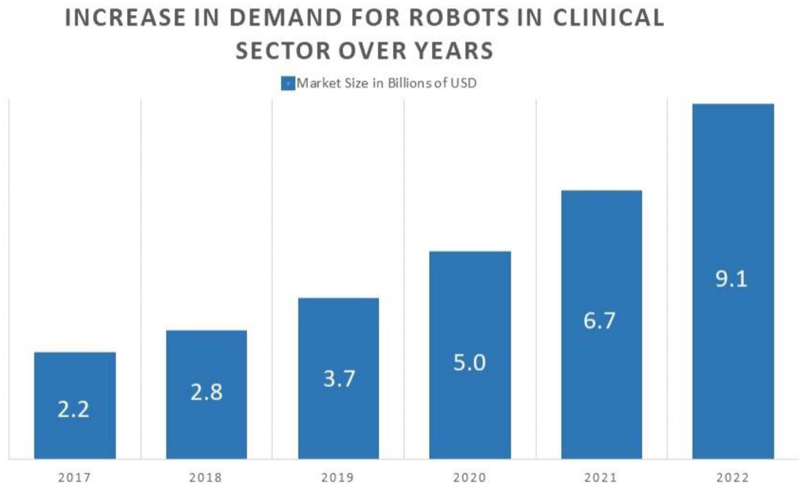
Figure 1. Market Demand Growth of Robots in Health Sector Over Years [19].
Sustainability 15 01647 g001
Figure 2. Head of Robo Doc: (a) Physical Design; (b) CAD Design.
Sustainability 15 01647 g002
Figure 3. Neck Design: (a) CAD Design of Neck Mechanism; (b) Physical Design of Neck Mechanism.
Sustainability 15 01647 g003
Figure 4. Neck View: (a) Side View of Neck; (b) Inside View of Neck (linking the head and neck of RoboDoc).
Sustainability 15 01647 g004
Figure 5. Left Arm of RoboDoc: (a) Left Arm CAD Design; (b) Physical Left Arm.
Sustainability 15 01647 g005
Figure 6. Right Arm of RoboDoc: (a) Right Arm CAD Design; (b) Physical Right Arm.
Sustainability 15 01647 g006
Figure 7. Torso: (a) CAD Design; (b) Physical Design.
Sustainability 15 01647 g007
Figure 8. Rover comprising of four wheels: two normal and two omni wheels.
Sustainability 15 01647 g008
Figure 9. Electronic Block Diagram and circuitry: (a) Block Flow Diagram; (b) physical electronic circuitry.
Sustainability 15 01647 g009aSustainability 15 01647 g009b
Figure 10. Control Unit Block.
Sustainability 15 01647 g010
Figure 11. Control Unit Block Circuit Diagrams: (a) Main Control Unit (MCU); (b) Power Supply Block.
Sustainability 15 01647 g011
Figure 12. Sensor Block Circuit Diagram: (a) FSR Sensor; (b) Proximity Sensor.
Sustainability 15 01647 g012
Figure 13. The Detailed Connection Description of Motor Driver (L298N) and the Motors: (a) Driver Block; (b) Motors Block.
Sustainability 15 01647 g013aSustainability 15 01647 g013b
Figure 14. Medical Tools Connected to Desktop Application Via Bluetooth and WiFi.
Sustainability 15 01647 g014
Figure 15. Haptics feedback: (a) Electronic Digital Stethoscope connected to the End of Linear Actuator; (b) Haptics Feedback Mechanism.
Sustainability 15 01647 g015
Figure 16. Desktop Application Dashboard: (a) E-Stethoscope Audio Auscultations; (b) Main Screen.
Sustainability 15 01647 g016
Figure 17. Desktop Application Dashboard: (a) Streaming Virtual Button; (b) Camera Live Streaming.
Sustainability 15 01647 g017
Figure 18. Video Calling Interface.
Sustainability 15 01647 g018
Figure 19. Tablet Control Mobile Application: (a) Switching Face Expressions of RoboDoc; (b) Pre-Written Text Window.
Sustainability 15 01647 g019
Figure 20. DSLR Camera Mechanism of RoboDoc: (a) Tilt Mechanism; (b) Zoom Mechanism.
Sustainability 15 01647 g020
Figure 21. DSLR Camera Control using Web Socket.
Sustainability 15 01647 g021
Figure 22. RoboDoc Block Diagram.
Sustainability 15 01647 g022
Figure 23. RoboDoc Interacting with People.
Sustainability 15 01647 g023
Figure 24. Demonstration of RoboDoc with a e-steth recording the Auscultations of the Subject: (a) RoboDoc Taking Data; (b) Live Audio Streaming on Remote Desktop Application (c) FSR Resistance vs. Vibratory Feedback (d) FSR Resistance vs. Patient Discomfort.
Sustainability 15 01647 g024aSustainability 15 01647 g024b
Figure 25. Demonstration of RoboDoc Recording the Temperature of the Subject: (a) RoboDoc Taking Data; (b) Demonstration of Live Data on Remote Desktop Application.
Sustainability 15 01647 g025
Figure 26. Demonstration of RoboDoc taking the pulse rate and SpO2 level of a subject and RoboDoc taking data (similar to Figure 25b).
Sustainability 15 01647 g026
Table 1. An overview of humanoid robotic platforms mechatronic design over a period of time.
S. NORobotic PlatformsMechanical DesignElectrical DesignAiHapticsDesktop InterfaceData LoggingTele OperatedSoft RoboticsReferences
DofEnd EffectorRoverMotorSensorController
NeckArmTorso
1ROHNI-124×Dispenser valve, pulse oximeterServo, dc motorHC-SR04, MLX90614, Ardu Cam PTZ, Quadrature Encoder MotorRaspberry Pi 3B+, PIC 18F4550×××[35]
2LIO×6×Gripper LiDARs, Distance sensor, Infrared floor sensors, Intel RealSense D435 Depth Camera, FSR4 embedded computing units: Intel NUC, Nvidia Jetson AGX Xavier, Raspberry Pi and an embedded PC with Atom processor×××[12]
3ARMAR374Gripperdc motorsultrasonic sensors, a planar laser-scanner, angle encoders, artificial skin, stereo camera system, stain gauges, gyroscopes and acceleration sensors, FasTrak (pos sensor), joint encoders, Artificial skin (tactile sensor)PC, C-167 micro-controllers, position joint controllers, 80C167 (microcontroller for motor), pc××××[24,25]
4JUSTIN2734 fingers× Torque sensor, (joints), 6-dof force/torque sensor at finger tips. Joint torque sensors, laser-range scanner, laser-stripe profiler, stereo camera sensorTorque and impedance controllers, local signal processor (embedded PC running linux),-×××[26,26,27,28]
5ARMAR III4735 fingers×ServoEncoder, Tactile sensor, strain gauge, load cells, optical sensor, quasi absolute angular sensortwo PC-104s, four Universal Controller Modules (UCoM), A/D converter, DC/DC converters and force-moment controllers××××[37]
6BHR-5272tennis×brushless DC motorsCameras, gyroscopes, accelerometers, six-axis force/torque sensors, encoderInertial sensor processor, motor controllers×××[29]
7MOBILE HUMANOID ROBOT260gripper(2dof)×6 dc motors, 8 servosWebcams(1.4 MP), Microphone laser range finder(URG-04LX-UG01), Potentiometers are used as the angle encoder for each joint with a resolution of 0.1 degreesPC××××[34]
8ALDEBARAN HUMANOID ROBOT2513 Fingers×DC motorsUSB camera, microphones, speakers, proprioceptive sensors. (locomotion sensors), accelerometer, gyroscopic sensor, resistance strain gauge (fsr)MOTHER BOARD: Korebot board, SERVO BOARD: Micro controller for PID control and I2C communication××××××[38]
9HUMANOID ROBOT LOLA332 ×PMSMsAngular sensor, camera, incremental rotary encoder, limit switch, fiber-optic gyroscopes, MEMS accelerometers, two six-axis force/torque sensors, strain gauges, temperature sensor, light-barrier, altitude sensorPC, central control unit (CCU- Core 2Duo Mobile, 2.33 GHz, running the QNX Neutrino real-time operating system) 3elmos controllers over CAN, inertial measuring unit {IMU iMAR iVRU-FC-C167×-×[30,31,32,33]
Table 2. Electrical and electronics components characteristics.
ComponentsAmps/VoltsSpecifications
SensorsHC-SR04 (Ultra-Sonic sensor)15 mA, 5 V DCMeasuring Range: 2–400 cm, accuracy: 3 mm
Micro Limit switch5 VThree pins: normally open (NO), normally closed (NC), neutral
Force Sensitive Resistor (FSR)<1 mA, 5 VDiameter: 12.5 mm, Force Range: (0 to 100 Newtons), Resistance Range: 100 KΩ (light pressure) to 200 Ω (max pressure)
ActuatorsDHV840 Servo motor6–7.4 VTorque: 34 kg-cm/6.0 V; 38 kg-cm/7.4 V, Speed: 0.21 s/60°/6.0 V; 0.18 s/60°/7.4 V
HP300 Servo Motor12–24 VMaximum torque: 300 kg/500 kg·cm (24 V), Operating Speed: 24 V 0.5 s/60° at no-load
RDS5160 Servo Motor6–8.4 VTorque: 58 kg·cm.at (6 v)
65 kg·cm.at (7.4 v)
70 kg·cm.at (8.4 v) Speed: 0.17 s/60 degree at (6 v)
0.15 s/60 degree at (7.4 v)
0.13 s/60 degree at (8.4 v)
XD-60GA775 DC, 5/50 RPM3 A, 12–24 VSpeed: 5/50 rpm Power: 35 W
Micro linear actuator12 V100 mm Stroke
Motor DriverL2986N2 A, 12 V
ControllerArduino Atmega 25602 A. 5 VDimensions and weight: 101.52 × 53.3 mm, 37 g
Raspberry Pi 43 A, 5 VPower via USB Type-C, 4 GB RAM
Power SupplyLead Acid Battery12 Ah, 12 V3.9 kg
LM2596 (Buck Converter)4.75 V–35 VOutput voltage:1.25–26 V(Adjustable)
Output current: Rated current is 2 A, maximum 3 A (Additional heat sink is required)
Table 3. Safety and Precautions.
S. No.ComponentSafety & Precautions
1Arms motorMercury limit switches to limit the arm movement in order to avoid wire twisting/stretching and collision with the camera stand
2Camera Zoom motor & Tilt MotorUse of 270-degree servo instead of continuous servo to avoid over rotation of the zoom lenses. Use of lever limit switches to limit the camera tilt.
3Main PCB circuitFuses for overcurrent protection, free-wheeling diode to suppress regenerative breaking, C3 Ac input cord for reverse polarity protection, use of crimp-seal connectors, screw terminals, lugs, heat shrink tubes to avoid loose connections. Replaceable modules and drivers. Thick tracks are used in PCBs are used to sustain any major current influx. Major connectors, connecting peripherals, are placed on one side of the PCB to avoid mishandling. Moreover, proper PCB labelling is ensured to mitigate any unforeseen safety hurdle. Proper labelling also ensures engineers/designers to place components properly. A blueprint (schematic) was created before designing the PCBs, and was thoroughly reviewed before production process.
4Neck movementUse of lever limit switches to limit the Head-Up and Head-Down movements.
5Collision AvoidanceHC-SR04 Ultrasonic Proximity Sensor
6Linear ActuatorBuilt-in micro limit switches to avoid over linear extension. The actuators used have limit switches on its either side.
7Wiring channelUse of wire sleeve conduits to through the wire along and provide flexible/safe movement while moving arm, with rubber bush endings. Major sections of wiring are kept isolated from each other in order to avoid any sparks. Proper heat sleaves adhere to maximum safety precautions.
8Battery Over-discharge protectionUse of cut-off circuit with the battery which will cut the robot’s supply if voltage drops below 10.5 V to protect it from over discharge.
9Battery Over-Charge protectionUse of a standard battery charger which has built-in charging cut-off circuit when the battery is fully charged.
10Low Battery Alarm IndicatorA LED push button with built-in LED has been used which will light up as an alarm when the cut-off circuit cut the robot supply in case the battery is low.
11On charging operationThe charging system is designed in such a way that we can also operate the robot even if it is charging. We do not need to wait for battery to get charged first.
Table 4. FSR resistance vs. patient comfort vs. vibration feedback.
S. No.ResistanceComfort Level of the PatientQuality of Heartbeat SoundStageXbox Vibration Feedback
1>20 KΩxNo Heartbeat sound or pure noiseWhen stethoscope does not touch the bodyNo Vibration
220 KΩ to 8 KΩEasily bearable for patientNoisy Unclear heartbeat sound wiWhen stethoscope has just touched the bodyPulsating vibration with more delay
38 KΩ to 1.5 KΩBearable for patient but not for long period of timeAudible heartbeat sound but the intensity is lowWhen Stethoscope slightly presses on the bodyPulsating vibration with less delay
4<1.5 KΩUnbearable for patient after few secondsClear heartbeat soundWhen Stethoscope presses hardly on the bodyContinuously vibrating
Disclaimer/Publisher’s Note: The statements, opinions and data contained in all publications are solely those of the individual author(s) and contributor(s) and not of MDPI and/or the editor(s). MDPI and/or the editor(s) disclaim responsibility for any injury to people or property resulting from any ideas, methods, instructions or products referred to in the content.