1. Introduction
Electric distribution systems are increasingly exposed to nonlinear loads associated with power electronics, controlled rectifiers, variable-speed drives, industrial converters, electric mobility interfaces, and electronically regulated loads. Although these technologies are essential for modern energy use, they can introduce current distortion, reactive power demand, voltage deviations, and additional losses in distribution feeders. From a sustainability perspective, these effects are not only concerns about power quality; they also reduce the effective utilization of electrical infrastructure, increase stress on conductors and transformers, and may lead to avoidable energy losses during operation [
1,
2,
3].
Power factor correction (PFC) has traditionally been used to reduce reactive power circulation and improve apparent power utilization in electrical networks. However, conventional compensation, focused only on the displacement power factor, is not sufficient when nonlinear loads dominate the feeder. In such cases, the distortion component of the current must also be considered, since harmonic currents can propagate through the network and deteriorate voltage quality at neighboring buses [
4,
5]. Therefore, active PFC schemes based on power electronic converters have become relevant for sustainable distribution systems, particularly when harmonic compliance, feeder loss reduction, and efficient infrastructure operation are required. Traditionally, engineers have addressed a low power factor and harmonic distortion using shunt capacitor banks, tuned passive filters, and centralized reactive-power compensation. These solutions are mature, simple, and widely used in distribution systems; however, they may be less effective when nonlinear loads dominate the feeder, because they do not actively reshape the distorted current waveform and may introduce resonance problems if harmonic conditions are not carefully considered. More recent solutions include shunt active power filters, DSTATCOMs, unified power-quality conditioners, multilevel converter-based compensators, and renewable-energy-assisted compensation systems. These approaches can provide effective harmonic mitigation and reactive power support, but they generally require additional power converters, multiple sensors, coordinated control loops, and greater implementation complexity.
In parallel, converter-based PFC stages have been widely used at the load interface to reduce the distortion and reactive current drawn by rectifier-fed equipment. This approach is attractive for retrofit applications because compensation is applied close to the nonlinear source, reducing unnecessary current circulation before it propagates through the feeder. Within this context, the Cuk converter is a suitable candidate because of its continuous-current characteristics, buck–boost capability, and compatibility with simplified DCM operation. Therefore, the present study evaluates a localized SCR–Cuk PFC scheme as a practical alternative for improving source-side power quality and reducing feeder-level losses in a radial distribution network.
Silicon-controlled rectifiers (SCRs) remain attractive in industrial applications due to their robustness, controllability, and suitability for high-current conversion stages. Nevertheless, their phase-controlled operation may degrade the input current waveform and produce a low power factor when no additional compensation stage is included [
6,
7]. Active PFC converters can address this limitation by reshaping the input current, reducing harmonic content, and supporting regulated DC-link operation. Among different topologies, the Cuk converter is technically attractive because it provides continuous input and output currents, capacitive energy transfer, and step-up/step-down voltage capability, which are useful characteristics for rectifier-fed loads [
8,
9,
10,
11].
Although system-wide reinforcement can improve voltage profiles and increase feeder capacity, it is not always the most sustainable or cost-effective response to power-quality degradation caused by localized nonlinear loads. Reinforcement actions such as conductor replacement, transformer uprating, or feeder reconfiguration require higher capital investment and longer implementation times and may not directly address the harmonic current injected by a specific nonlinear device. In contrast, localized PFC can be installed near the dominant disturbance source, reducing unnecessary current circulation before the disturbance propagates through the feeder. This retrofit-oriented approach is particularly attractive in modern distribution grids where nonlinear loads are spatially concentrated at specific buses, such as industrial rectifiers, electronically controlled loads, electric-mobility interfaces, or converter-fed equipment.
From a sustainability perspective, localized PFC also avoids oversizing the entire feeder to solve a disturbance produced at a limited point of common coupling. By improving the current waveform near the nonlinear source, localized compensation can reduce feeder losses, thermal stress, and apparent-power demand while preserving the existing distribution infrastructure. Therefore, the main research gap addressed in this work is not only the design of a converter-level PFC stage, but the evaluation of how a localized SCR–Cuk PFC device affects feeder-level indicators such as nodal THD, voltage deviation, active and reactive power flows, and line losses.
Recent PFC studies have investigated bridgeless topologies, hybrid switched-capacitor cells, resonant AC–DC converters, and multilevel interleaved rectifiers [
8,
9,
12]. These approaches have improved converter-level efficiency, input current shaping, and harmonic performance. However, many analyses focus on the converter terminals and do not quantify the impact of a localized PFC stage on feeder-level variables, including nodal THD, voltage deviation, active and reactive power flows, and line losses. This network-level view is important because a sustainable compensation strategy should be evaluated not only by the waveform observed at the source, but also by its impact on the distribution system in which it is installed.
This paper addresses this gap by assessing an SCR–Cuk PFC scheme in the IEEE 13-bus radial distribution test feeder. The nonlinear load is installed at node 634, a low-voltage node supplied by a 500 kVA transformer. Two operating scenarios are compared: (i) an uncompensated case without PFC and (ii) a compensated case in which a DCM Cuk converter is used as an active PFC stage. The study evaluates both local and feeder-level performance indicators under the same operating conditions, including source-side power factor and THD, bus harmonic distortion, voltage deviation, active and reactive power flows, and line losses.
The main contributions of this work can be summarized as follows:
An SCR–Cuk PFC structure operating with a DCM Cuk converter is evaluated as an active compensation stage for a nonlinear load connected to a radial distribution feeder.
The proposed scheme is analyzed using the IEEE 13-bus distribution test system, enabling quantification of both local and feeder-level power-quality effects.
A comparative assessment between uncompensated and compensated scenarios is performed using power factor, source current THD, nodal THD, voltage deviation, active and reactive power flows, and line losses.
The sustainability implications of localized active PFC are discussed in terms of harmonic mitigation, loss reduction, improved infrastructure utilization, and the possible need for distributed compensation in harmonic-sensitive nodes.
The remainder of this paper is organized as follows.
Section 2 presents the state of the art in power-quality enhancement, active PFC converters, and distribution-level compensation approaches.
Section 3 summarizes the technical background of power factor correction, SCR rectifiers, and Cuk converters.
Section 4 describes the benchmark feeder, the proposed SCR–Cuk PFC configuration, and the simulation scenarios.
Section 5 presents and discusses the results.
Section 6 describes the sustainability implications of the proposed compensation scheme. Finally,
Section 7 summarizes the main conclusions and future work.
2. State of the Art
The increasing penetration of nonlinear loads, power-electronic interfaces, renewable energy systems, and electronically controlled industrial equipment has intensified power-quality challenges in modern distribution networks. Harmonic distortion, poor power factor, voltage deviation, and increased active and reactive power losses are no longer isolated load-side issues; rather, they can propagate through feeders and affect voltage regulation, transformer loading, conductor stress, and overall distribution-system efficiency. The recent literature has therefore shifted from simple load-level compensation to system-level power-quality enhancement strategies, in which harmonic mitigation, power factor correction (PFC), loss reduction, and voltage-profile improvement are evaluated jointly.
Recent studies show that unified power-quality conditioners (UPQCs), distribution static compensators (DSTATCOMs), shunt active power filters (SAPFs), multilevel converters, and renewable-energy-assisted compensation systems are the dominant solutions for power-quality improvement in distribution networks. Mahela et al. [
13] proposed a DSTATCOM with battery energy storage for harmonic mitigation and power-quality improvement in a utility grid with high solar photovoltaic penetration, and validated the approach using MATLAB/Simulink 2025a and real-time digital simulation. Their results demonstrated reductions in total harmonic distortion (THD) across different operating conditions, confirming the usefulness of converter-based compensation in distribution grids with high levels of renewable penetration. Similarly, Ray et al. [
14] investigated a photovoltaic-integrated UPQC for power-quality enhancement and power-flow management in distribution networks, using an adaptive variable-leaky least-mean-square algorithm to improve compensation under grid disturbances and nonlinear loading conditions. Smadi et al. [
15] also investigated PV-UPQC operation using PI-SRF and power-angle-control strategies, emphasizing the role of coordinated series and shunt compensation in mitigating current and voltage harmonics.
UPQC-based compensation remains one of the most widely reported strategies because it can simultaneously address voltage-side and current-side disturbances. Trivedi et al. [
16] developed a sliding-mode-based direct power control for UPQC operation, reporting low source-current THD and line-loss reductions in weak-grid conditions. In the same direction, Khademi and Jahromi [
17] proposed a controller for PV-UPQC integration under nonlinear load conditions. These studies confirm that UPQC systems are effective for comprehensive compensation; however, their dual-converter structure, DC-link requirements, and sensing/control complexity may limit their use in practical retrofit applications, where a simpler PFC stage is desirable.
Shunt active filters and multilevel inverter-based compensators have also been extensively studied. Agrawal et al. [
18] introduced a three-level cascade H-bridge inverter-based compensator, using a Trianguzoidal PWM technique to enhance power quality in single-phase distribution systems with fixed and dynamic loads. Tajik and Yeh [
19] proposed an adaptive shunt active filter based on a double-flying-capacitor multicell converter and artificial neural network control, and validated the method on an IEEE 13-bus system under nonlinear and unbalanced conditions. Nallaiyagounder et al. [
20] used a photovoltaic-based q-ZSI STATCOM with an MDNESOGI control scheme for harmonic mitigation, achieving current THD values within IEEE 519 limits. Boopathi and Indragandhi [
21] developed a predictive direct-power-controlled PV-interfaced multilevel inverter SAPF, reporting a power factor improvement from 0.79 to 0.99 and a current THD reduction from 25.403% to 1.826%. These contributions demonstrate the strong performance of active and multilevel compensation systems, especially when combined with predictive or intelligent control; nevertheless, they generally require more switches, higher control effort, and more complex implementation than single-stage PFC converters.
From a converter-topology perspective, recent research has increasingly focused on high-power-density, high-efficiency PFC rectifiers. Kharade et al. [
22] studied multilevel rectifiers for high-power-density converters with PFC, focusing on improved efficiency and reduced harmonic distortion, while Lopez-Martin et al. [
23] explored residential smart grid power-quality enhancement through adaptive PFC stages. Although these studies provide relevant background for PFC control and conduction-mode selection, most focus on boost-type or general PFC stages rather than on Cuk-based PFC in the context of a multi-bus distribution network.
The Cuk converter is particularly attractive for PFC because it provides buck–boost voltage conversion, continuous input current, and reduced input-current ripple compared with some conventional rectifier front-end solutions. Marimuthu and Umamaheswari [
24] analyzed a single-stage bridgeless Cuk converter for current harmonic suppression using a particle swarm optimization-based controller, reporting near-unity power factor and high efficiency while satisfying IEC 61000-3-2 requirements. Venkateswarlu and Pakkiraiah [
25] investigated a PV-integrated Cuk converter for UPQC applications, highlighting its suitability for improving power quality and introducing intelligent control. These studies support the technical potential of the Cuk topology; however, their scope is mainly at the converter level, UPQC-associated, or application-specific. They do not comprehensively evaluate how a DCM Cuk-based PFC stage affects harmonic propagation, voltage deviation, power flows, or active/reactive losses in a standardized radial distribution network. The literature also shows a growing connection between the improvement of power quality and sustainability. A common limitation of previous Cuk-based PFC studies is that the assessment is mainly performed at the converter terminals. In such analyses, the principal indicators are usually input current THD, output-voltage regulation, power factor, efficiency, or controller performance. Although these indicators are necessary, they do not reveal how the compensated nonlinear load modifies the behavior of the surrounding distribution feeder. In practical radial networks, harmonic distortion and reactive-current circulation depend not only on the converter but also on feeder impedance, transformer coupling, load distribution, and the electrical distance between buses. Therefore, a converter that performs well at its own terminals may still produce different impacts on nodal THD, voltage deviation, power flows, and losses throughout the feeder. This distinction defines the main contribution of the present work. Unlike converter-level Cuk PFC studies, the proposed assessment links the operation of a DCM Cuk-based PFC stage to network-level performance on the IEEE 13-bus radial distribution feeder. This allows the study to quantify whether localized compensation at node 634 improves only the source-side waveform or also contributes to feeder-level sustainability indicators such as loss reduction and reduced thermal stress. A poor power factor and harmonic distortion increase the RMS current, copper losses, thermal stress, and equipment derating, thereby directly affecting distribution-system efficiency and infrastructure lifetime. Coman et al. [
1] showed that distributed power factor correction can improve the efficiency and sustainability of power systems, while Dan et al. [
26] reported loss and voltage-THD reductions using a distributed power-flow controller topology. These works reinforce the relevance of power-quality compensation as a sustainability-oriented measure, as reducing harmonic currents and reactive power flow can improve feeder efficiency and reduce unnecessary electrical stress.
Despite these advances, several research gaps remain. First, most recent studies focus on UPQC, DSTATCOM, SAPF, multilevel inverter, or renewable-integrated compensation schemes, while Cuk-based PFC remains comparatively under-represented. Second, available studies on Cuk converters generally emphasize continuous conduction mode, bridgeless configurations, or converter-level performance, with limited attention to DCM operation. This is important because DCM can simplify control and provide inherent current shaping, which is attractive for low-cost PFC implementation. Third, very few studies evaluate PFC performance using standardized multi-bus radial distribution systems such as the IEEE 13-bus feeder. Consequently, the impact of compensation on voltage deviation, harmonic propagation, active/reactive power flows, and feeder losses is often not quantified. Fourth, the integration of an SCR rectifier with an active Cuk-based PFC stage has not been sufficiently explored as a practical retrofit-oriented solution for nonlinear loads in distribution systems. Finally, sustainability metrics, such as active and reactive loss reduction, feeder efficiency, and localized versus system-wide compensation effects, are still not consistently integrated into PFC studies.
Based on these gaps, the present work proposes and evaluates a DCM Cuk-based PFC scheme integrated with an SCR rectifier in an IEEE 13-bus radial distribution system under nonlinear load conditions. Unlike converter-only studies, the proposed assessment considers both local and network-level indicators, including power factor, source-current THD, bus-level harmonic distortion, voltage deviation, active and reactive power flows, and active/reactive line losses. This positioning enables the study to link converter-level PFC operation with sustainable distribution-network performance, providing a practical contribution to improving power quality and improving energy efficiency in radial feeders. The comparative evidence in
Table 1 indicates that most recent studies prioritize UPQC, SAPF, STATCOM, and multilevel converter solutions. In contrast, Cuk-based PFC, especially in DCM and integrated with SCR rectifiers, remains insufficiently explored at the distribution-system level. This motivates the proposed evaluation on the IEEE 13-bus radial feeder.
4. Materials and Methods
4.1. Benchmark Distribution System
The test platform is based on the IEEE 13-bus radial distribution feeder, a compact but technically demanding benchmark system for distribution-level studies. This feeder includes unbalanced loads, overhead and underground line sections, voltage regulation equipment, shunt capacitor banks, and distribution transformers. These characteristics make it suitable for evaluating power-quality disturbances and compensation effects under realistic radial feeder conditions.
The main source is represented by a substation transformer rated at 5000 kVA with a 115 kV/4.16 kV transformation ratio. A 500 kVA transformer located between nodes 633 and 634 reduces the voltage level from 4.16 kV to 0.48 kV. Node 634 is selected as the point of common coupling because it combines two relevant characteristics for this study. First, it is located on the low-voltage side of the 4.16/0.48 kV transformer, between nodes 633 and 634, which makes it a realistic connection point for low-voltage rectifier-fed nonlinear loads and retrofit PFC devices. Second, it has a significant baseline unbalanced demand, with phase powers of 160 kW/110 kVAr, 120 kW/90 kVAr, and 120 kW/90 kVAr. Therefore, the selection is based on both the electrical location and baseline unbalance. This makes node 634 suitable for evaluating how a localized compensation device affects the point of common coupling and the upstream feeder sections.
The load at node 634 is modeled as a three-phase unbalanced Y-PQ load. According to the baseline feeder data, the phase powers at this node are 160 kW/110 kVAr, 120 kW/90 kVAr, and 120 kW/90 kVAr.
In addition to the baseline Y-PQ demand, a 10 kW nonlinear rectifier-fed branch is connected at node 634 to evaluate the proposed SCR–Cuk PFC stage. This rating is not intended to replace the complete node demand; instead, it represents a localized nonlinear sub-load connected at the low-voltage bus. This modeling choice emulates a practical retrofit condition in which a specific rectifier-fed load branch is compensated while the node’s remaining baseline demand is preserved. Therefore, the objective is not to claim full compensation of node 634, but to quantify how a localized SCR–Cuk PFC device modifies source-side and feeder-level indicators when installed at a low-voltage point of common coupling.
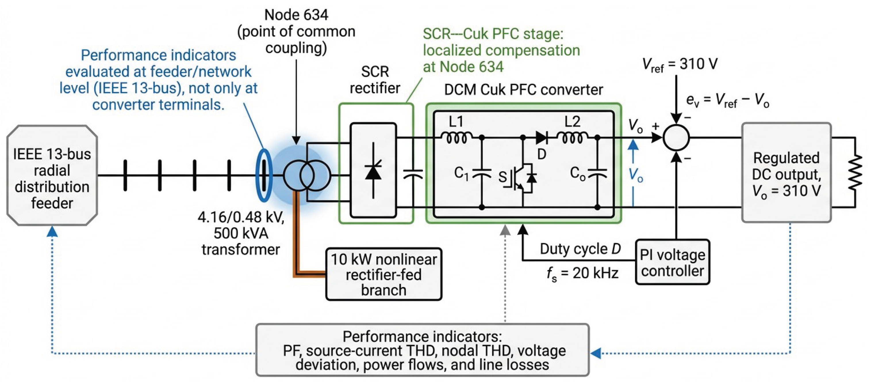
The nonlinear behavior is introduced through an SCR rectifier stage. In the compensated case, a Cuk converter operating as an active PFC stage is integrated with the rectifier system. The conceptual structure of the study is shown in
Figure 1.
4.2. Proposed SCR–Cuk PFC Configuration
The proposed configuration integrates a controlled rectifier and a Cuk converter for active power factor correction. The SCR rectifier provides the AC–DC conversion stage while the Cuk converter is used to improve the input current profile and support DC output voltage regulation. In this study, the rectified DC-link voltage is set to 310 V, and the regulated output voltage reference is also fixed at 310 V. The converter design assumes a load power of 10 kW and a switching frequency of 20 kHz.
The 10 kW rating corresponds to the nonlinear rectifier-fed load branch used to evaluate the SCR–Cuk PFC stage. The remaining demand at node 634 is represented by the IEEE 13-bus feeder’s baseline unbalanced Y-PQ load. Therefore, the proposed PFC stage is assessed as a localized compensation device connected to the nonlinear portion of the load, rather than as a full replacement for the node demand.
The Cuk converter operates in discontinuous conduction mode (DCM), which is attractive for PFC applications because it simplifies the control structure and supports input current shaping. The control scheme uses a voltage-regulation loop. The output voltage is compared with the reference voltage, and the resulting error is processed by a proportional–integral (PI) controller. The controller output defines the modulation signal that adjusts the switch duty cycle. Thus, the converter is designed to maintain the DC output voltage while reducing source-current distortion and improving the source-side power factor.
Figure 2 summarizes the electrical and control structure of the proposed compensation stage. The SCR rectifier provides the controlled AC–DC conversion, while the DCM Cuk converter regulates the DC output voltage and supports input-current shaping. The output-voltage error is processed by a PI controller, whose output defines the duty-cycle command applied to the converter switch.
It is important to clarify that the proposed SCR–Cuk PFC stage is not implemented as a selective harmonic compensator. Therefore, the control strategy does not require prior detection of individual harmonic orders or the generation of specific compensating harmonic currents. Instead, harmonic mitigation is achieved indirectly through input-current shaping. In DCM operation, the Cuk converter behaves as a power-processing stage whose average input current can be shaped by the duty-cycle command imposed by the voltage-regulation loop. By regulating the DC output voltage and maintaining the converter within the selected operating region, the input current drawn from the AC source becomes smoother and more closely aligned with the supply voltage. As a consequence, the low-order harmonic components produced by the SCR rectifier are reduced at the source side.
Thus, the proposed method should be interpreted as a power factor-correction front-end with harmonic-reduction capability, rather than as an active power filter with selective harmonic detection and compensation. The effectiveness of this mechanism is evaluated a posteriori using the source-current harmonic spectrum and the total harmonic distortion index.
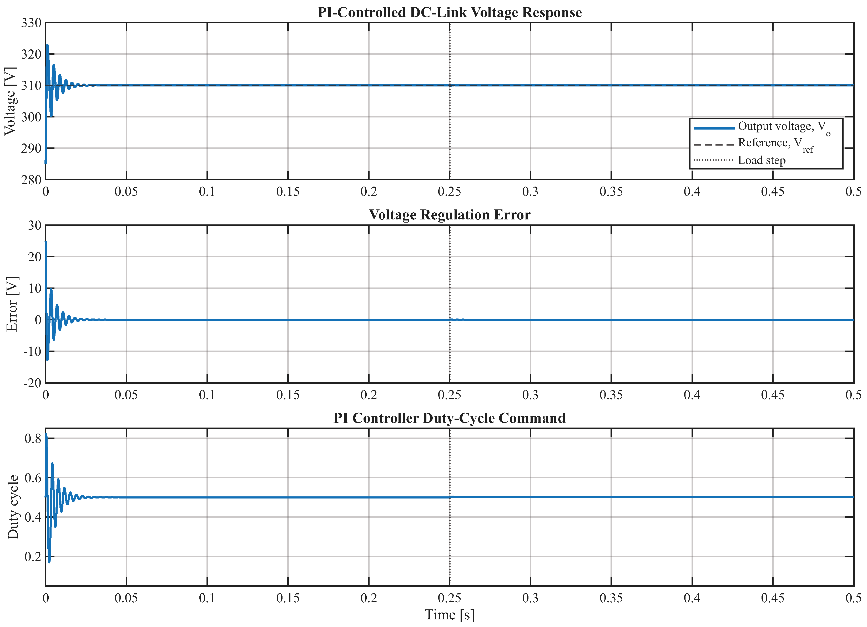
The PI controller gains were selected to obtain a stable DC-link voltage response during the simulated operating window while avoiding excessive transient overshoot. The tuning process prioritized steady-state voltage regulation and source-current shaping under the nonlinear load condition considered in this study. Since the objective of this work is to assess the feeder-level impact of the SCR–Cuk PFC stage rather than to propose a new control-tuning method, the PI controller is used as a conventional voltage-regulation mechanism. The resulting voltage-regulation behavior is illustrated in
Figure 3.
Table 2 summarizes the main converter parameters used in the study.
Figure 3 shows that the output voltage converges to the 310 V reference and recovers after the load disturbance without sustained oscillations. The duty-cycle command remains within the predefined operating limits, supporting the use of the PI loop as a conventional voltage-regulation mechanism for the simulated operating window.
The PI-controlled response shows a fast convergence toward the 310 V reference, with a bounded transient and negligible steady-state error after the initial settling interval. After the load disturbance, the controller restores the output voltage without sustained oscillations, while the duty-cycle command remains within the predefined operating limits. This response supports using the PI loop as a conventional voltage-regulation mechanism within the simulated operating window.
To make the numerical assessment reproducible, the main simulation and measurement settings are summarized in
Table 3. These settings define the benchmark feeder, the nonlinear load location, the electrical frequency, the simulation window, and the performance indicators used to compare the uncompensated and compensated scenarios. This information is included to clarify how the source-side and feeder-level results were obtained under the same operating conditions. After the initial transient interval, the source-side power factor and current THD were evaluated using the steady-state current and voltage signals. The source-current THD was obtained from the current spectrum, whereas the nodal THD values were recorded at the corresponding distribution buses. Active and reactive power flows, voltage deviations, and line losses were evaluated for the feeder sections most affected by the nonlinear load and the compensation stage. The converter and power-quality waveforms were obtained in MATLAB/Simulink, while the feeder-level variables were evaluated using the IEEE 13-bus distribution model.
4.3. Simulation Scenarios and Performance Indicators
Two operating scenarios are evaluated under the same feeder and load conditions. In the uncompensated scenario, the nonlinear load is supplied without the Cuk-based PFC stage, establishing the baseline power-quality condition of the feeder. In the compensated scenario, the SCR rectifier is integrated with the DCM Cuk-based PFC stage to evaluate the improvement obtained with localized active compensation.
The study was carried out in a simulation environment. The SCR rectifier, the DCM Cuk converter, the PI voltage-regulation loop, the PWM duty-cycle generation, and the source-side voltage/current waveforms were implemented in MATLAB/Simulink using Simscape Electrical components. The harmonic spectrum and source-current THD were obtained from the steady-state simulated current waveform after the initial transient interval. The feeder-level assessment was performed using the IEEE 13-bus radial distribution feeder model, where the nodal THD, voltage deviation, power flows, and line losses were evaluated for the uncompensated and compensated scenarios. No physical experimental prototype was used in this work; therefore, the results correspond to a simulation-based assessment under the operating conditions defined in
Table 3.
Keeping the feeder configuration and load demand unchanged in both cases allows the effect of the proposed compensation stage to be isolated. Therefore, differences in power factor, harmonic distortion, voltage deviation, power flows, and losses can be attributed to the inclusion of the SCR–Cuk PFC structure.
The comparison is performed using both converter-level and feeder-level indicators. At the local/source side, the evaluated variables include voltage and current waveforms, source-side power factor, and source current total harmonic distortion (THD). At the feeder level, the analysis includes voltage deviation at the distribution nodes, nodal THD, local power factor at node 634, active and reactive power flows through the main feeder sections, and active and reactive line losses.
This combined evaluation is necessary because a compensation device may improve the waveform observed at the rectifier or source terminals without fully correcting harmonic propagation throughout the feeder. For this reason, the proposed assessment distinguishes between source-side improvement and network-level impact. This distinction is also relevant for determining whether localized compensation is sufficient or whether additional distributed compensation may be required at other harmonic-sensitive nodes.
Unlike conventional capacitor-bank compensation or STATCOM-based reactive-power control, the proposed SCR–Cuk PFC stage does not compute an explicit reactive-power compensation command. The power factor improvement is obtained through source-current reshaping and reduction of the distortion and reactive components associated with the nonlinear rectifier-fed branch. For performance evaluation, the apparent power, power factor, and reactive power were calculated from the simulated rms voltage, rms current, and active power as
and
These quantities were used to compare the uncompensated and compensated cases under the same feeder and load conditions. Therefore, the reported improvement in power factor is not the result of a separately sized reactive-power compensator, but of the reduction in unnecessary current circulation achieved by the SCR–Cuk PFC stage.
4.4. DCM Operation Verification
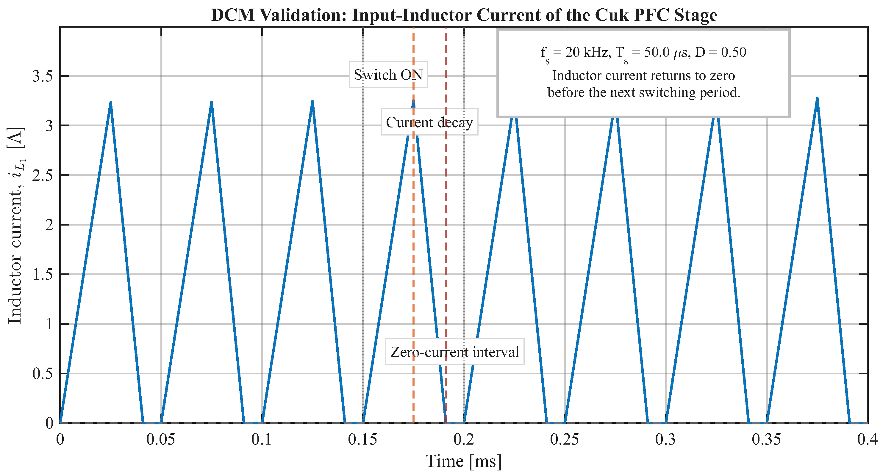
To support DCM operation, the switching-period behavior of the Cuk input-inductor current was verified at the nominal operating point. For the selected switching frequency of 20 kHz, the switching period is
s. Under the nominal duty cycle
, the simulated input-inductor current rises during the switch-on interval, decreases during the energy-transfer interval, and reaches zero before the next switching period begins. The existence of this zero-current interval confirms discontinuous conduction at the evaluated operating point.
Figure 4 shows the representative switching-period behavior of the Cuk input-inductor current.
5. Results and Discussion
5.1. Source-Side Power Quality
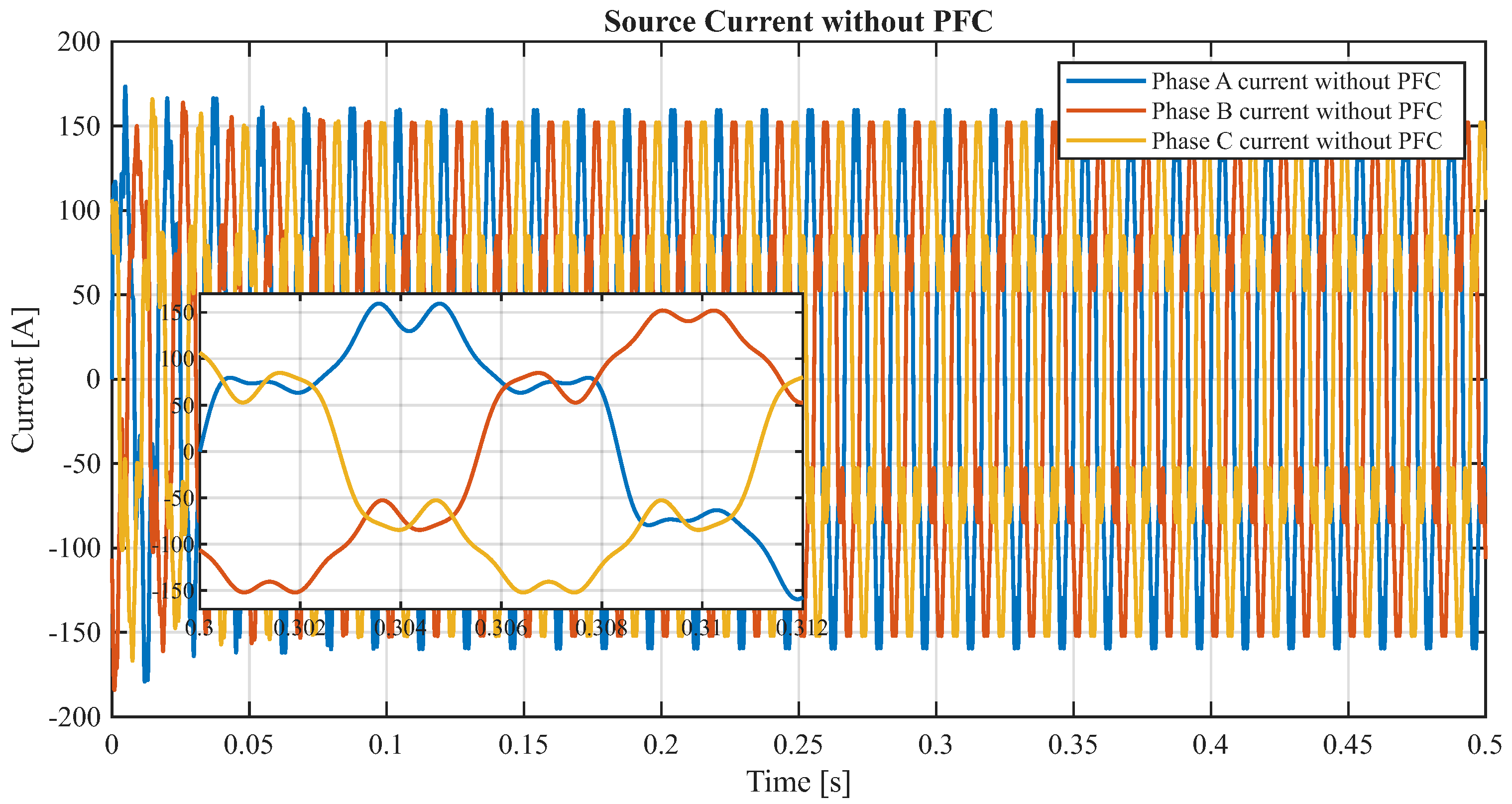
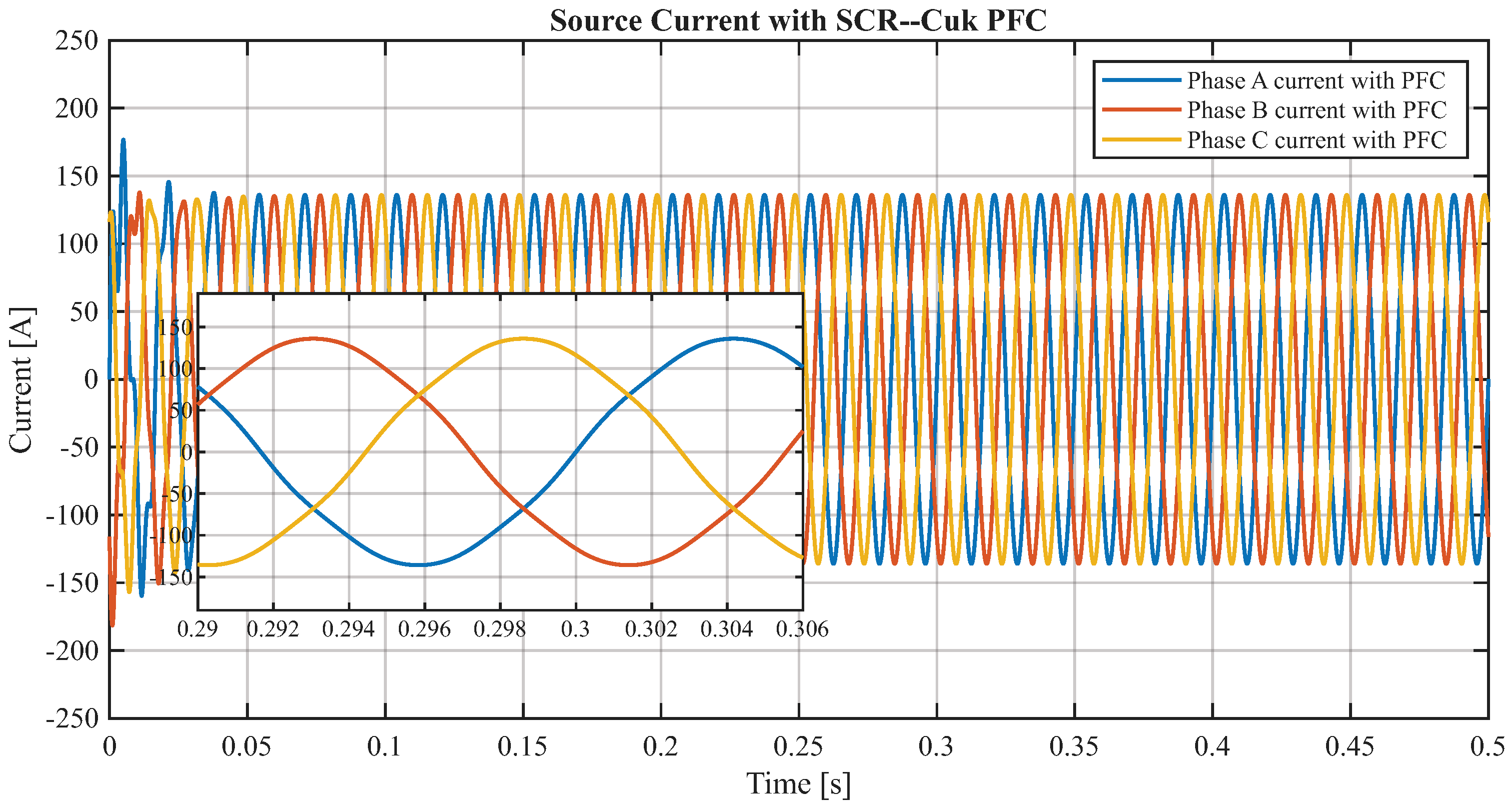
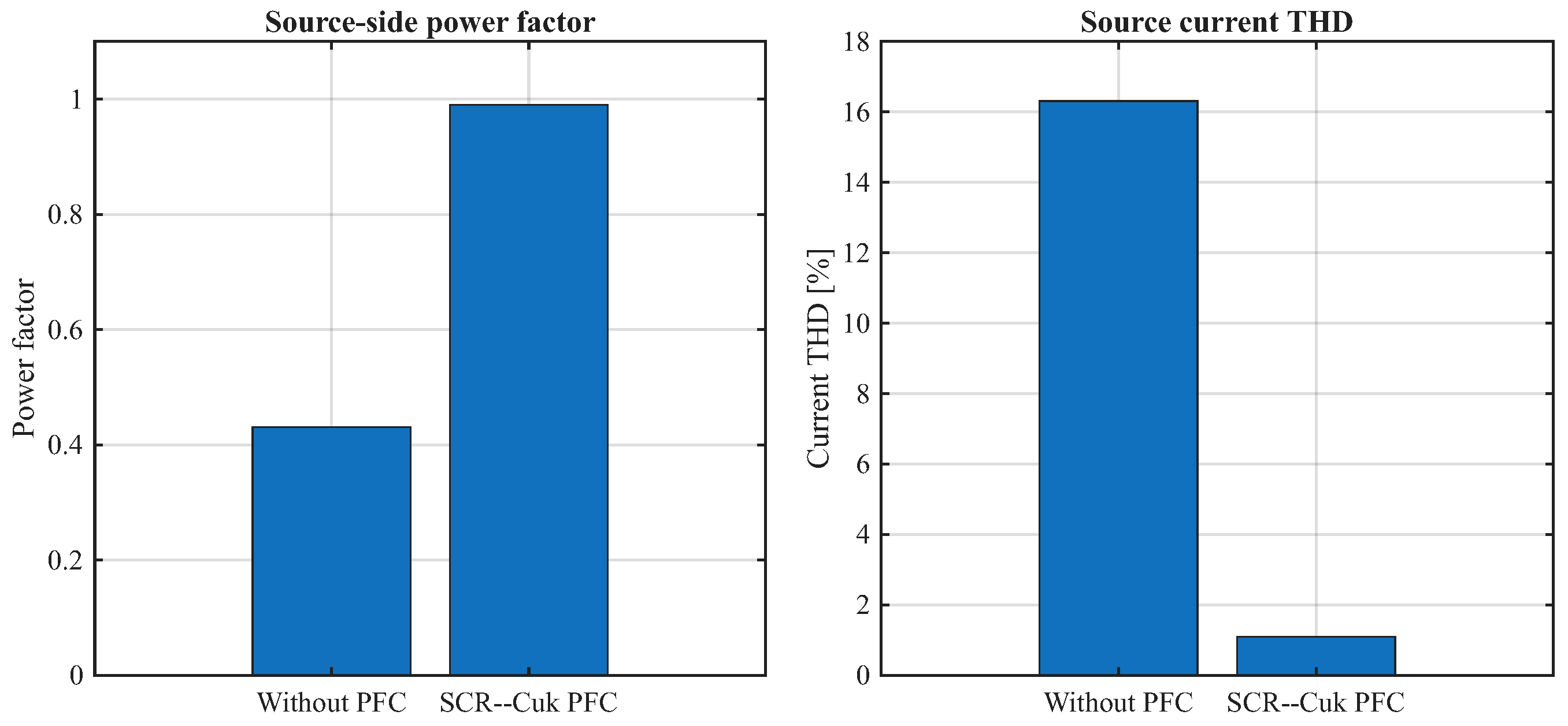
In the uncompensated scenario, the source voltage remains sinusoidal, but the source current presents a highly distorted waveform. This distortion is caused by the rectifier-fed load’s nonlinear behavior. The baseline power factor is 0.431, indicating poor use of apparent power and a significant mismatch between voltage and current. The source current THD reaches 16.31%, exceeding the 5% reference limit adopted in many harmonic-control studies based on IEEE Std 519 [
28]. The corresponding three-phase source current waveforms are shown in
Figure 5 and
Figure 6.
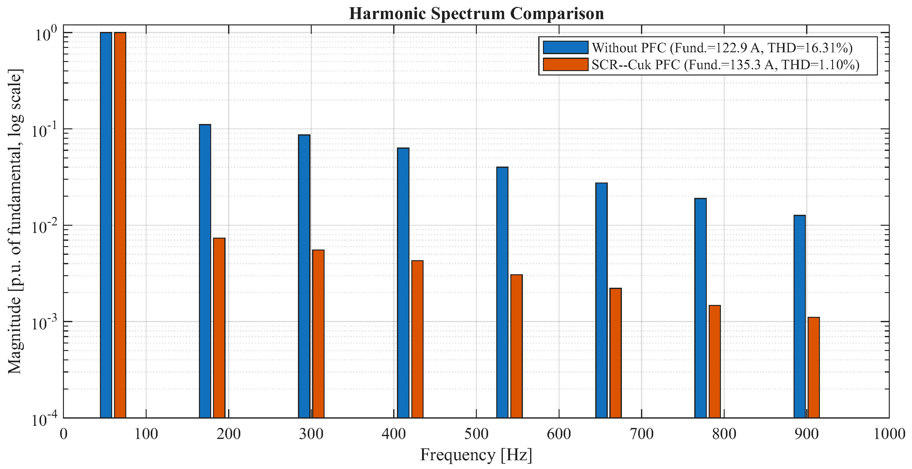
The harmonic spectrum in
Figure 7 confirms that the SCR–Cuk PFC stage reduces the dominant harmonic components associated with the nonlinear rectifier-fed load. This reduction is obtained without selective harmonic detection. The converter does not identify a specific harmonic order to be compensated; instead, the DCM Cuk stage modifies the input-current profile of the rectifier-fed branch. Consequently, the harmonic spectrum improves as a result of current shaping at the source side. This behavior is consistent with the objective of a PFC front-end, whose primary function is to improve the current waveform and power factor rather than to operate as a selective active harmonic filter.
When the DCM Cuk-based PFC stage is included, the source current becomes nearly sinusoidal and more aligned with the supply voltage. This behavior can be observed by comparing
Figure 5 and
Figure 6. In the uncompensated case, the three-phase currents exhibit narrow, distorted peaks due to the nonlinear rectifier-fed branch.
These peaks increase the rms current for the same useful active-power transfer, which explains the low power factor and the higher feeder stress observed before compensation. In contrast, the compensated case shows smoother phase currents with a more regular sinusoidal shape, indicating that the Cuk stage reshapes the input current drawn from the source.
The frequency-domain result in
Figure 7 confirms this waveform improvement. The dominant low-order harmonic components are strongly attenuated after compensation, which reduces the source-current THD from 16.31% to 1.10%. This corresponds to a relative THD reduction of approximately 93.3%. At the same time, the power factor increases from 0.431 to 0.99, as summarized in
Figure 8. Therefore, the proposed SCR–Cuk PFC scheme improves both components of the total power factor: the displacement component, by aligning the current more closely with the supply voltage, and the distortion component, by reducing harmonic current injection.
These results are particularly relevant because the source-side condition changes from a non-compliant harmonic condition to a condition below the 5% reference level adopted in this study. Nevertheless, this source-side improvement should not be interpreted as complete feeder-wide harmonic mitigation. As discussed in the following subsection, the nodal THD results show that harmonic propagation also depends on feeder impedance, load distribution, and the electrical distance from the compensated nonlinear branch.
Table 4 presents the global comparison. The improvement in THD is particularly relevant because it changes the system from a non-compliant harmonic condition to a compliant source-side condition.
5.2. Nodal Harmonic Behavior
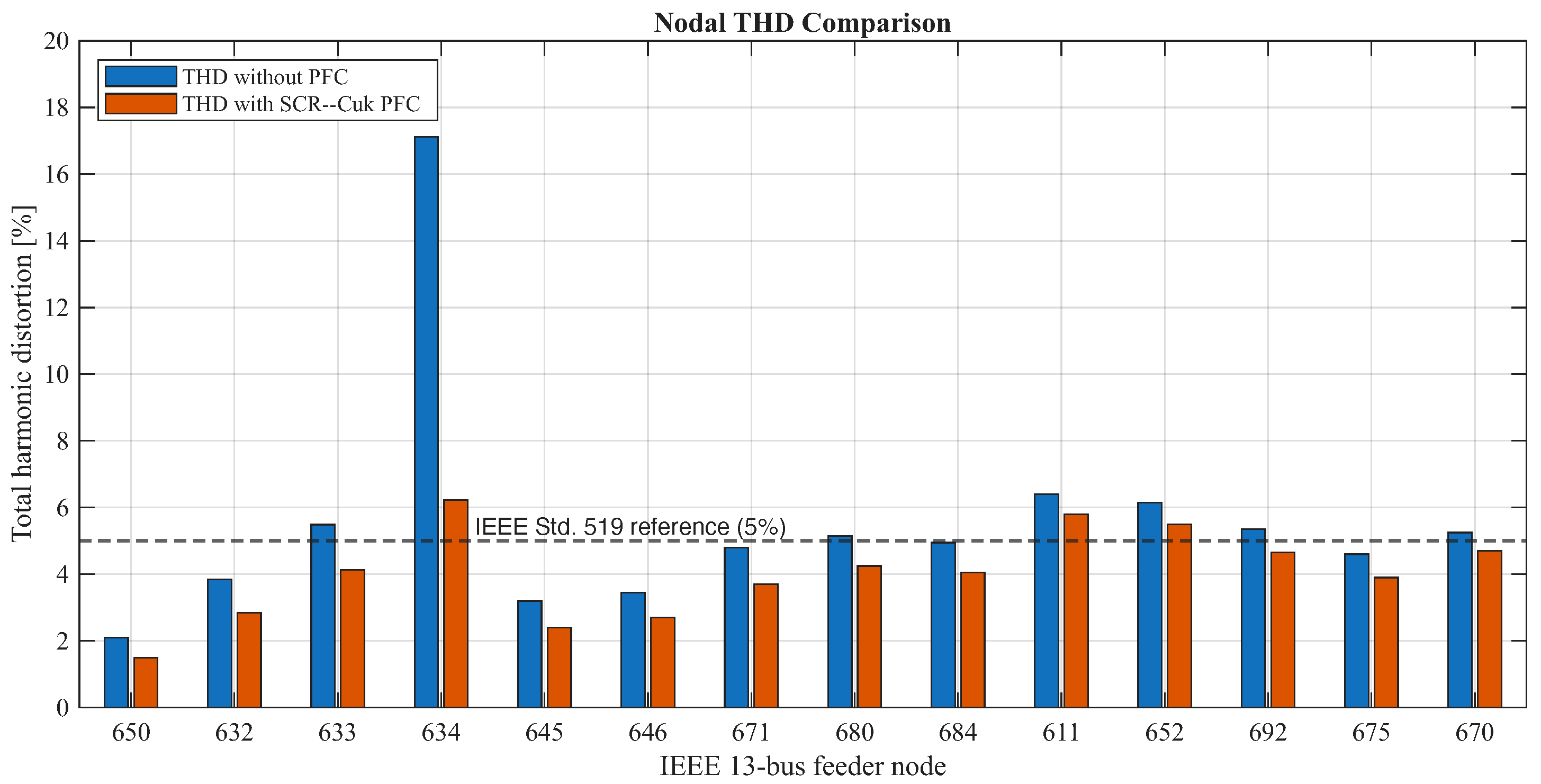
The network-level THD results show that the nonlinear load connected at node 634 affects not only the local node but also other buses in the feeder. In the uncompensated case, node 634 reaches a THD of 17.12%, the highest reported in the studied feeder. Neighboring or electrically related nodes also present distortion values that may exceed the 5% reference limit.
In
Figure 9, the horizontal axis represents the actual IEEE feeder bus numbers rather than a generic plotting index. Therefore, the interpretation of the THD values can be directly related to the electrical location of each bus within the radial feeder, while the interpretation of the THD values must be made according to the electrical location of each bus. The highest distortion appears at node 634 because this is the point of common coupling of the nonlinear rectifier-fed branch. Therefore, the voltage waveform at this node is directly affected by the harmonic current injected by the SCR load. Node 633, which is electrically adjacent to node 634 through the 4.16/0.48 kV transformer connection, also presents relevant distortion in the uncompensated case.
The reduction pattern after compensation is not uniform across all nodes. This is expected in a radial feeder because nodal THD depends on the local short-circuit strength, the impedance path between the nonlinear source and each bus, transformer coupling, and the distribution of linear and nonlinear loads. Consequently, buses electrically closer to the compensated branch show clearer improvement, whereas remote or differently loaded buses may retain distortion levels above the 5% reference. This behavior confirms that the SCR–Cuk PFC stage is highly effective as a localized compensation device, but feeder-wide harmonic compliance may require coordinated placement of additional compensation units.
With the proposed compensation scheme, node 634 decreases from 17.12% to 6.23%. Node 633 also improves from 5.49% to 4.13%, entering the acceptable range. However, some remote or differently loaded nodes remain above the 5% reference, such as nodes 611 and 652. This indicates that the Cuk PFC stage provides strong localized compensation but does not fully eliminate feeder-wide harmonic propagation.
Figure 9 shows the nodal THD comparison using the values reported in the study.
This result is technically important because a source-side assessment alone may suggest complete harmonic mitigation when the current THD is reduced to 1.10%. The feeder-level analysis provides a more rigorous interpretation: the source-side current is substantially improved, but localized compensation at node 634 cannot guarantee full harmonic compliance at every node of the network. Therefore, feeder-wide compliance may require coordinated placement of additional compensation devices at harmonic-sensitive nodes.
5.3. Voltage Deviation and Local Power Factor
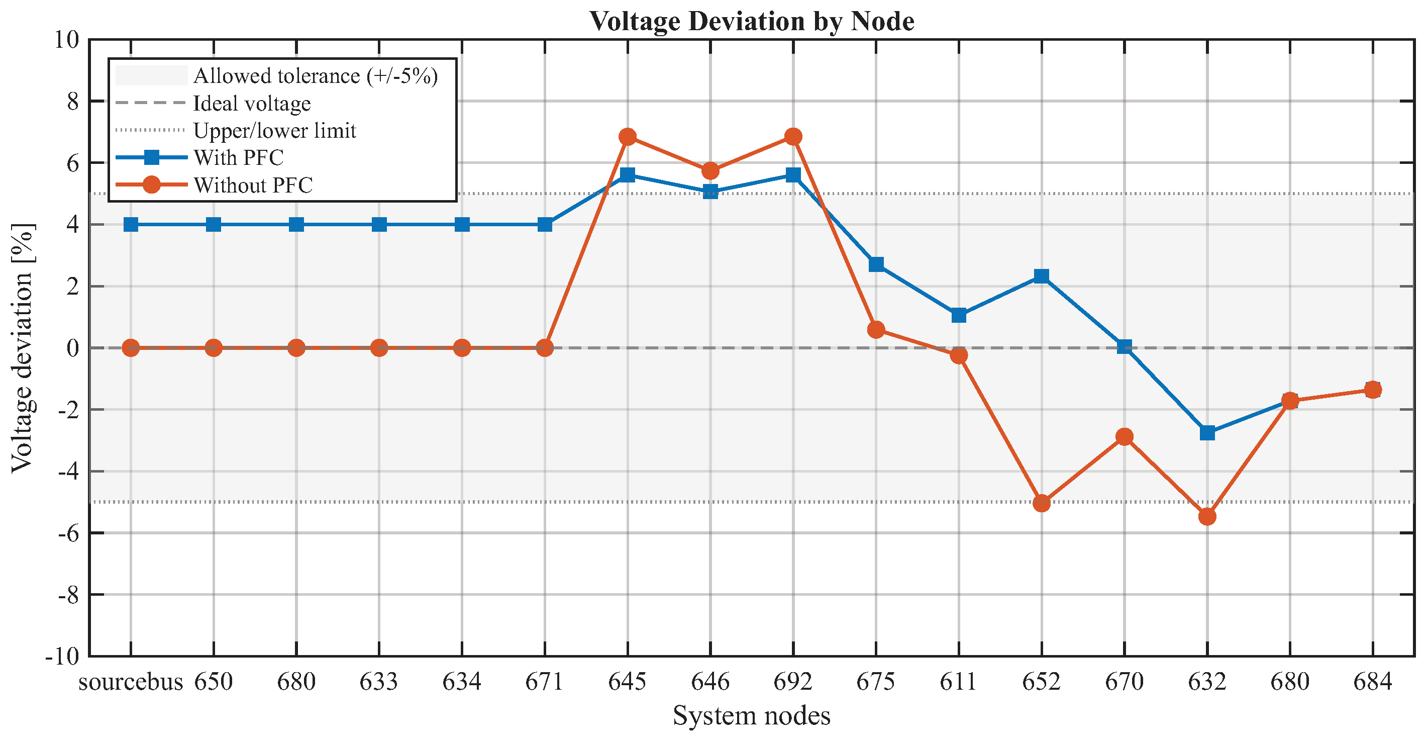
The voltage deviation analysis indicates that, in the uncompensated case, deviations exceed the desired range at some nodes. Nodes 645 and 692 present positive deviations of 6.84% and 6.85%, respectively, while nodes 670 and 680 present negative deviations of −5.04% and −5.47%. After including the Cuk PFC stage, negative deviations decrease, and the maximum positive deviations approach the upper acceptable margin. This behavior indicates that the compensation modifies the feeder electrical stress and improves the voltage profile in the most affected zones.
Figure 10 illustrates the voltage-deviation behavior for both scenarios.
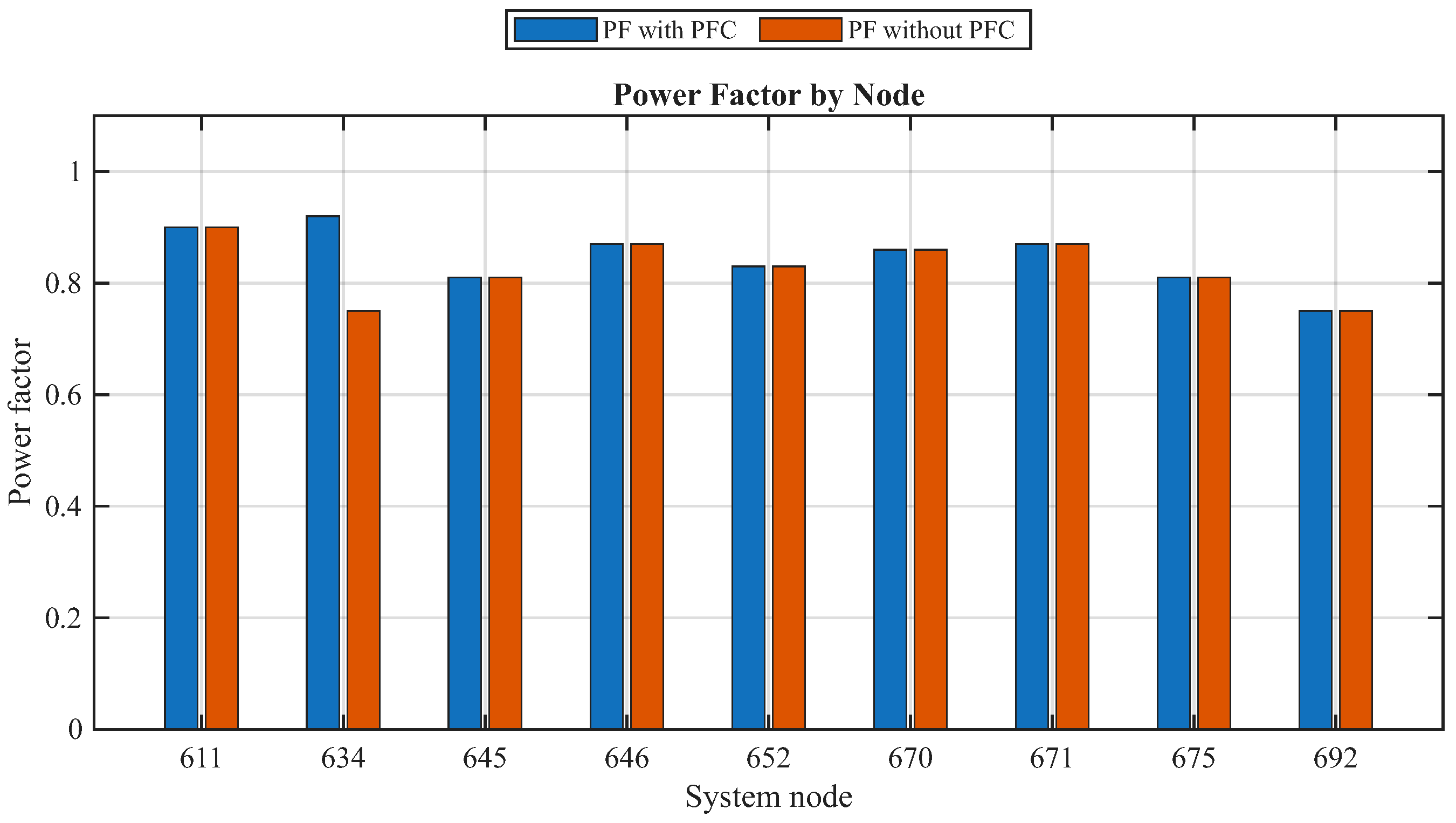
The local power factor at node 634 increases from 0.75 to 0.92, while the remaining nodes show only minor variations. This behavior confirms that the compensating effect is primarily local, which is consistent with distributed PFC theory: a compensator installed at one node improves the reactive and harmonic behavior of that node and its electrical vicinity, but it should not be expected to correct unrelated loads installed in other feeder sections.
Figure 11 is therefore included to support the interpretation that the proposed SCR–Cuk PFC stage acts as a localized compensation device rather than as a feeder-wide correction mechanism.
5.4. Active and Reactive Power Flows
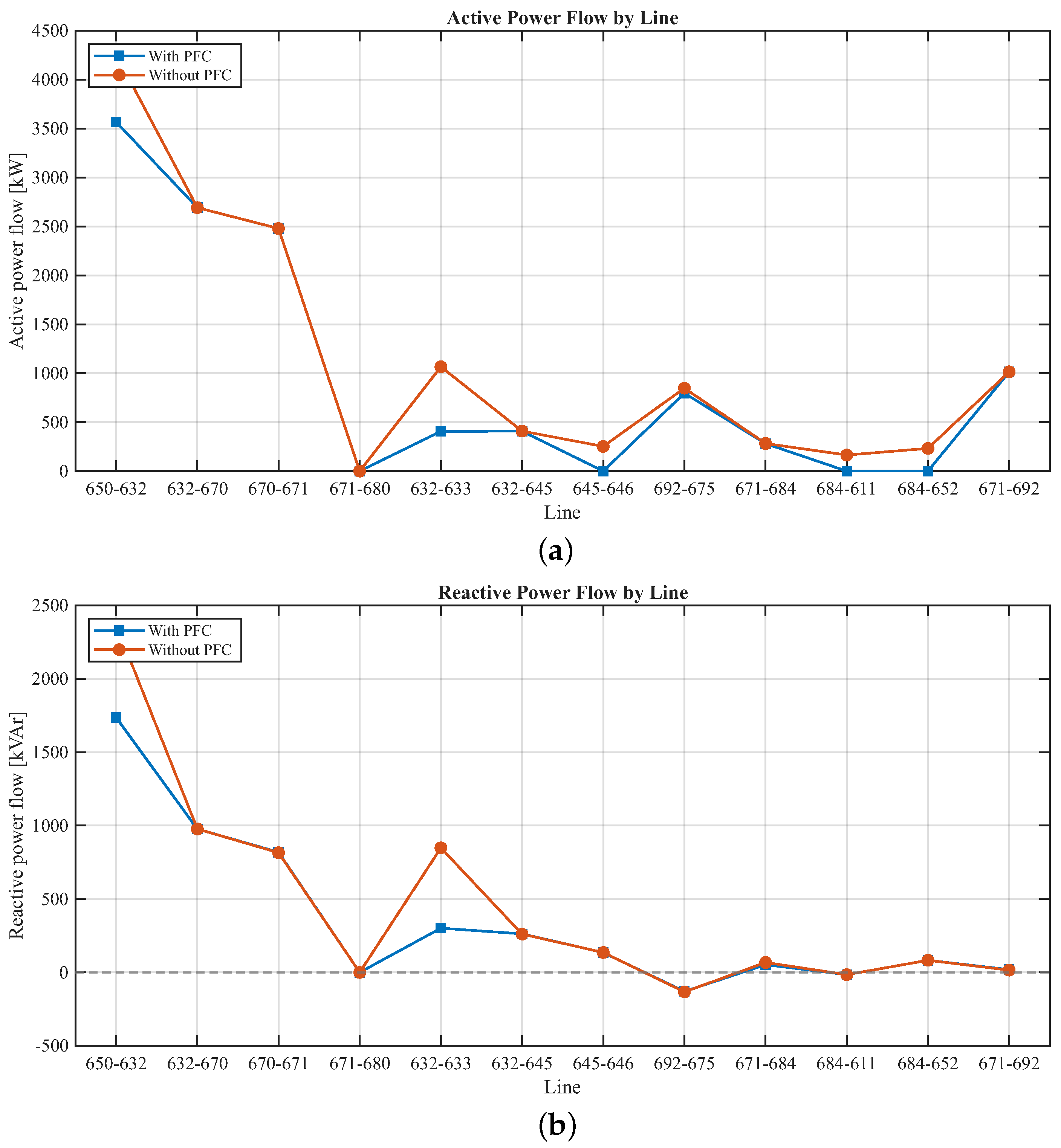
The active power flow results show that the compensation mainly affects the feeders electrically connected to node 634. Line 650–632 decreases from 4255.81 kW to 3566.70 kW, while line 632–633 decreases from 1065.99 kW to 406.38 kW. These changes indicate a lower power-circulation requirement for the routes feeding the nonlinear load after compensation. The remaining lines show minor variations, which again confirms the localized nature of the intervention.
The reactive power flow shows a similar pattern (
Figure 12). In line 650–632, reactive power decreases from 2367.91 kVAr to 1735.85 kVAr. In line 632–633, the reduction is stronger, from 848.26 kVAr to 301.15 kVAr. This is expected because the PFC directly targets unnecessary reactive and distortion-related current flow. Lower reactive flow is beneficial for sustainable operation because it frees up network capacity and reduces unnecessary current in the feeder.
5.5. Line Losses
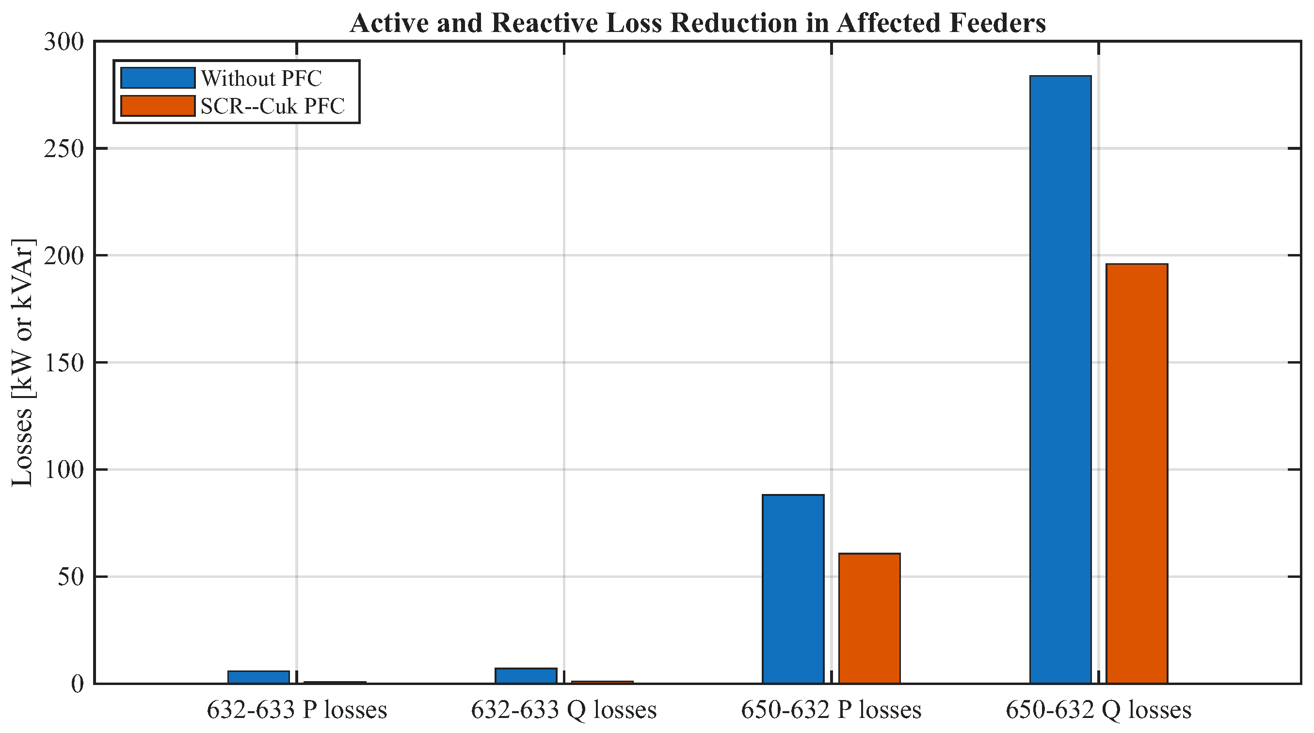
The loss analysis confirms the operational benefit of the compensation scheme. In the line 650–632, active losses decrease from 88.08 kW to 60.73 kW. In line 632–633, active losses decrease from 5.82 kW to 0.82 kW. Reactive losses also decrease substantially: from 283.73 kVAr to 195.99 kVAr in line 650–632 and from 7.06 kVAr to 1.06 kVAr in line 632–633.
Figure 13 summarizes the most affected feeder losses.
Table 5 presents the same results numerically. The reductions are concentrated on the lines supplying the compensated node, which is consistent with the radial topology of the test feeder.
To further quantify the operational implication of these loss reductions, the active line-loss decrease was used as a thermal-stress proxy, since conductor and transformer heating are directly related to the resistive loss component
. For the two feeder sections most affected by the nonlinear branch, the total active-loss reduction is
This value represents avoided heat generation in the corresponding feeder sections under the simulated operating condition. Therefore, if the same operating condition were maintained for one hour, the avoided wasted energy would be
Using the Ecuadorian grid emission factor for energy-efficiency projects,
[
29], the corresponding avoided-emission potential can be estimated as
Thus, the compensated case avoids approximately
for each hour in which the simulated operating condition is maintained. This value is not intended as an annual emission claim, but as an operating-point indicator that links power-quality improvement with reduced thermal stress, avoided wasted energy, and emission-reduction potential, as summarized in
Table 6.
5.6. Discussion of Technical Findings
The results demonstrate that the DCM Cuk-based PFC stage substantially improves the source-side current drawn by the nonlinear load. The increase in power factor from 0.431 to 0.99 and the reduction in current THD from 16.31% to 1.10% represent a substantial improvement in power quality. These values support the technical suitability of the Cuk converter as an active PFC stage for rectifier-fed loads.
At the same time, the feeder-level results show that localized compensation has limits. Because the SCR–Cuk PFC stage is connected to a 10 kW nonlinear branch rather than to the full node demand, the results should be interpreted as the effect of localized compensation at a dominant disturbance point. This explains why source-side current quality improves substantially, while some feeder nodes still require coordinated compensation to satisfy network-wide harmonic limits. The THD at node 634 decreases significantly but remains slightly above the 5% reference value. Some other buses also remain above the limit. This should be interpreted as a limitation of localized compensation under the tested network conditions, because harmonic propagation in distribution networks depends on network impedance, load distribution, and the location of nonlinear sources. In practical networks, full compliance may require a coordinated compensation strategy rather than a single device. The scope of this study is limited to simulation-based assessment under the operating conditions defined for the IEEE 13-bus feeder and the selected nonlinear load location. The proposed SCR–Cuk PFC stage is evaluated as a localized compensation solution; therefore, the results should not be interpreted as a guarantee of feeder-wide harmonic compliance under all possible loading conditions. Future work should include experimental validation, sensitivity analysis under different nonlinear-branch ratings and load levels, and coordinated placement of multiple compensation devices.
6. Sustainability Implications
The proposed compensation scheme contributes to the sustainable operation of the distribution system in three main ways. First, it reduces current distortion and improves the power factor, allowing the feeder to deliver useful active power with lower apparent power demand. Second, it reduces active and reactive losses in the main affected lines, thereby reducing wasted energy and lowering thermal stress in conductors and transformers. Third, it improves voltage deviation behavior across several nodes, thereby supporting better service quality and potentially increasing the lifetime of connected equipment.
For the most affected feeder sections, active-loss reductions were 31.05% in line 650–632 and 85.91% in line 632–633. Reactive-loss reductions were also significant, reaching 30.92% in line 650–632 and 84.99% in line 632–633. Since active losses represent resistive heating, these reductions also provide a quantitative proxy for reduced thermal stress in the affected feeder sections. Considering only the active-loss reduction in these two lines, the compensated case avoids approximately 32.35 kW of heat generation under the simulated operating condition. Because the simulation window is 0.5 s, the reported loss values should be interpreted as steady-state power-loss indicators rather than accumulated energy over the simulated interval. If the compensated operating point were maintained for 1 h, the avoided waste energy would be approximately 32.35 kWh. Using the Ecuadorian grid emission factor for energy-efficiency projects, this operating-point saving is equivalent to approximately 10.85 kgCO2eq of avoided emissions. This estimate is not intended as an annual emission claim, but it illustrates how power-quality compensation can translate into energy-efficiency, thermal-stress, and emission-reduction benefits in radial distribution operation.
From an energy-management perspective, localized PFC is attractive because it can be installed near dominant nonlinear loads rather than relying solely on feeder-wide reinforcement. This targeted strategy reduces unnecessary current circulation near the disturbance source, lowers losses, and promotes more efficient use of existing distribution infrastructure.
However, the results also indicate that a single compensator may not guarantee feeder-wide harmonic compliance. Therefore, the most sustainable implementation strategy should combine local active PFC at dominant nonlinear loads with feeder-level monitoring to identify additional nodes where compensation may be required. This coordinated approach would avoid unnecessary oversizing while improving network-wide power quality.
7. Conclusions
This paper presents a sustainable power-quality enhancement assessment of a DCM Cuk-based PFC scheme integrated with an SCR rectifier. The IEEE 13-bus radial distribution test feeder was used as the benchmark system, and the nonlinear load was connected at node 634. Two scenarios were compared: an uncompensated case and a compensated case using the SCR–Cuk PFC structure.
The source-side results showed a strong improvement. The power factor increased from 0.431 to 0.99, while the source current THD decreased from 16.31% to 1.10%. These results indicate that the proposed converter can substantially reshape the source current and achieve harmonic levels below the 5% reference limit at the supply side. The current waveform also became nearly sinusoidal after compensation.
The proposed control should be interpreted as a DCM-based input-current-shaping strategy. It does not require selective harmonic detection or an explicit reactive-power compensation command, because the improvement is obtained by regulating the DC output voltage and modifying the current drawn by the nonlinear rectifier-fed branch.
At the feeder level, the THD of node 634 decreased from 17.12% to 6.23%, and that of node 633 decreased from 5.49% to 4.13%. The local power factor at node 634 improved from 0.75 to 0.92. In addition, the main affected feeders exhibited significant loss reductions. Active losses in line 650–632 decreased from 88.08 kW to 60.73 kW, and active losses in line 632–633 decreased from 5.82 kW to 0.82 kW. Reactive losses followed the same trend.
The findings show that the DCM Cuk-based PFC scheme can significantly improve source-side power quality and reduce losses in the affected feeder sections. Nevertheless, the remaining THD values at some nodes indicate that feeder-wide compliance may require coordinated or distributed compensation. Future work should investigate the coordinated placement and sizing of multiple SCR–Cuk PFC units across different feeder branches, considering variations in nonlinear-load penetration, feeder impedance, and operating conditions. Experimental validation using a laboratory prototype or hardware-in-the-loop platform should also be developed to confirm the dynamic response and practical implementation limits of the proposed scheme.
From an engineering and policy perspective, the results support the inclusion of localized power-quality compensation as part of energy-efficiency planning in distribution networks. Utilities and regulators could promote feeder-level harmonic monitoring, require harmonic-impact assessment for large nonlinear loads, and encourage targeted PFC installation near dominant distortion sources before considering costly system-wide reinforcement. Such measures would help reduce losses, thermal stress, and avoidable emissions while improving the use of existing electrical infrastructure.