
Microstructure and Mechanical Properties of Sustainable Concrete Incorporating Used Foundry Sand and Coal Bottom Ash


Abstract
1. Introduction
2. Materials and Methods
2.1. Materials
2.1.1. Cement
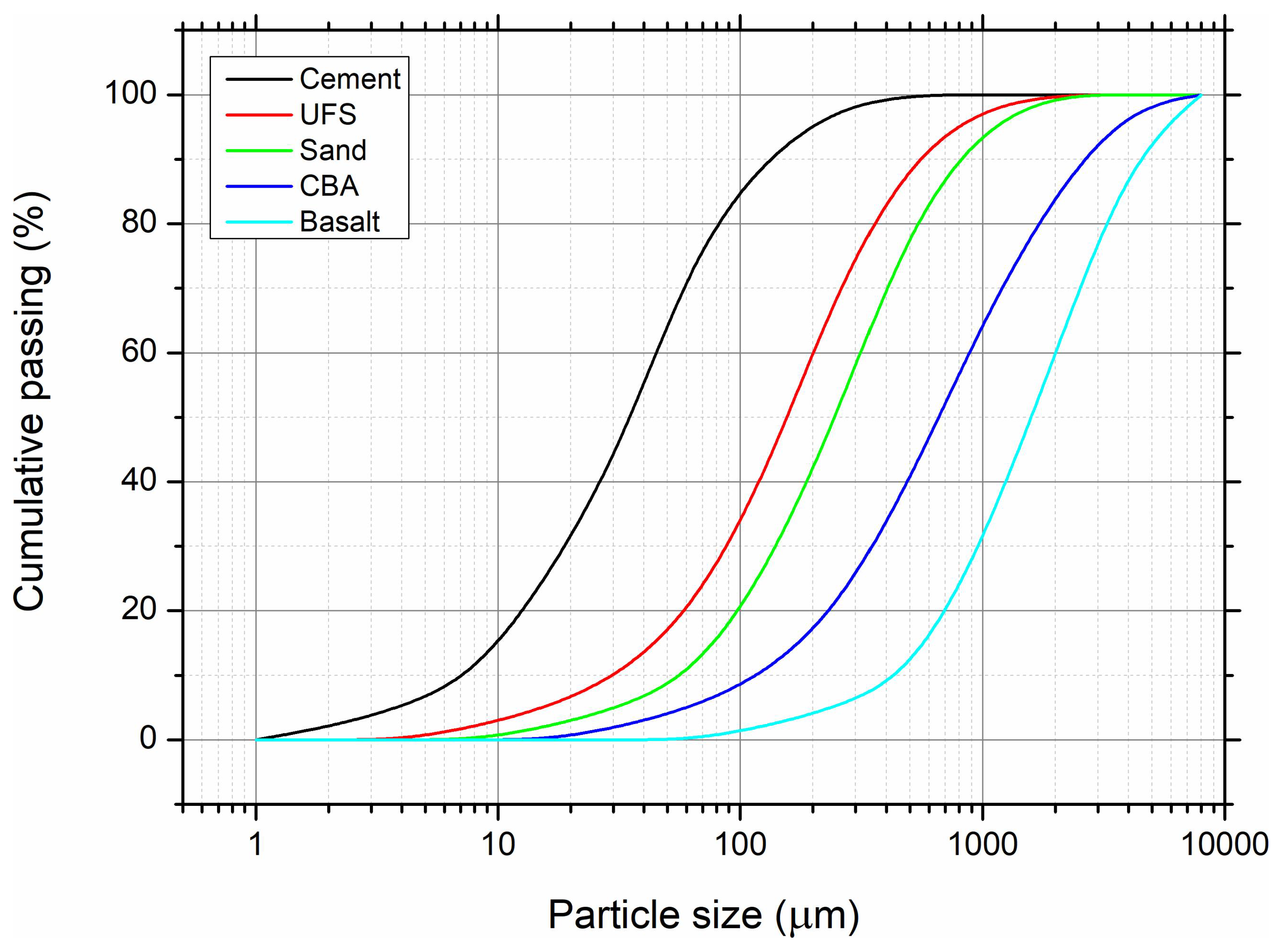
2.1.2. Natural Aggregates
2.1.3. UFS
2.1.4. CBA
2.1.5. Admixture
2.2. Mix Proportions and Specimen Preparation
2.3. Testing Methods
2.3.1. XRD
2.3.2. SEM and EDS
2.3.3. Compressive Strength Test
3. Results and Discussion
3.1. Mineralogical Characterization of XRD
3.1.1. Characterization of UFS
3.1.2. Characterization of CBA
3.1.3. Concrete
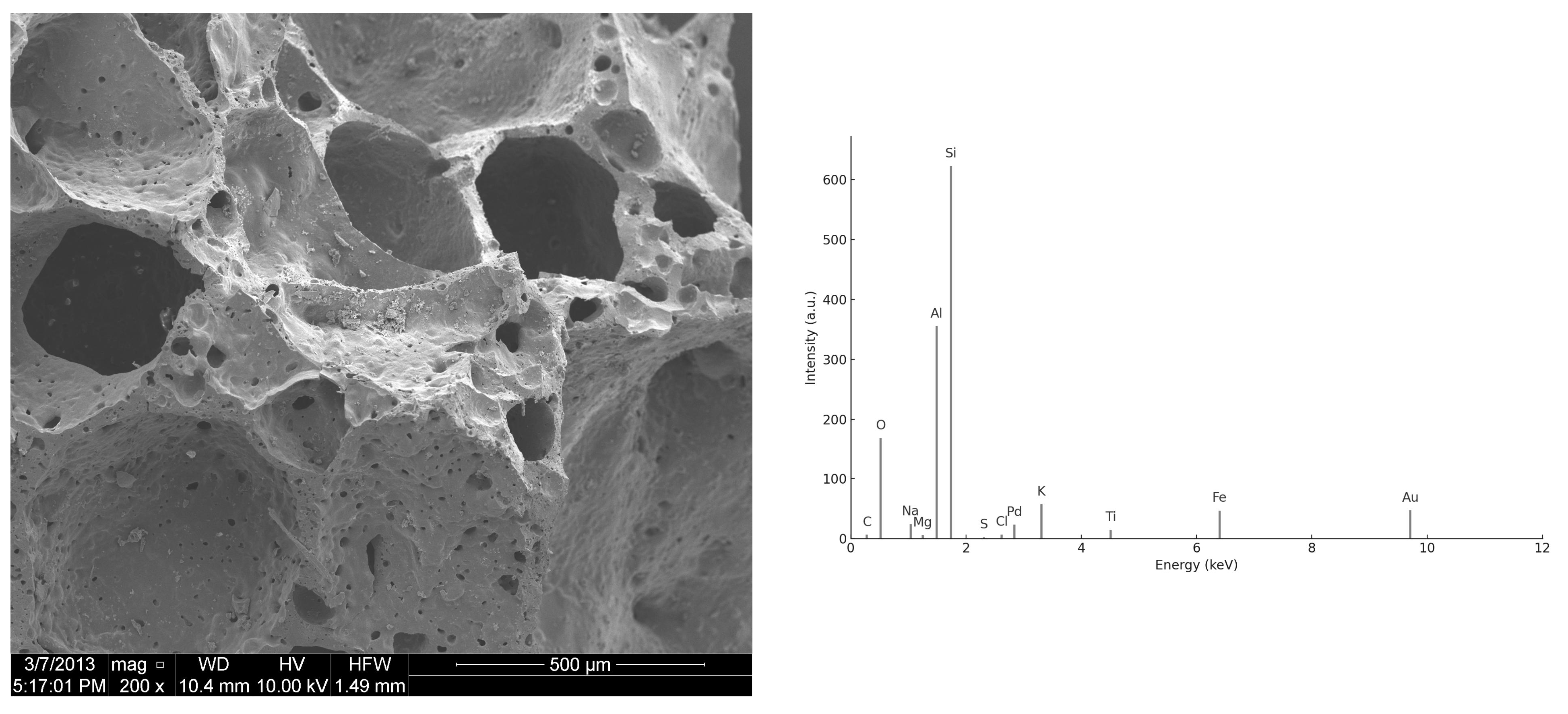
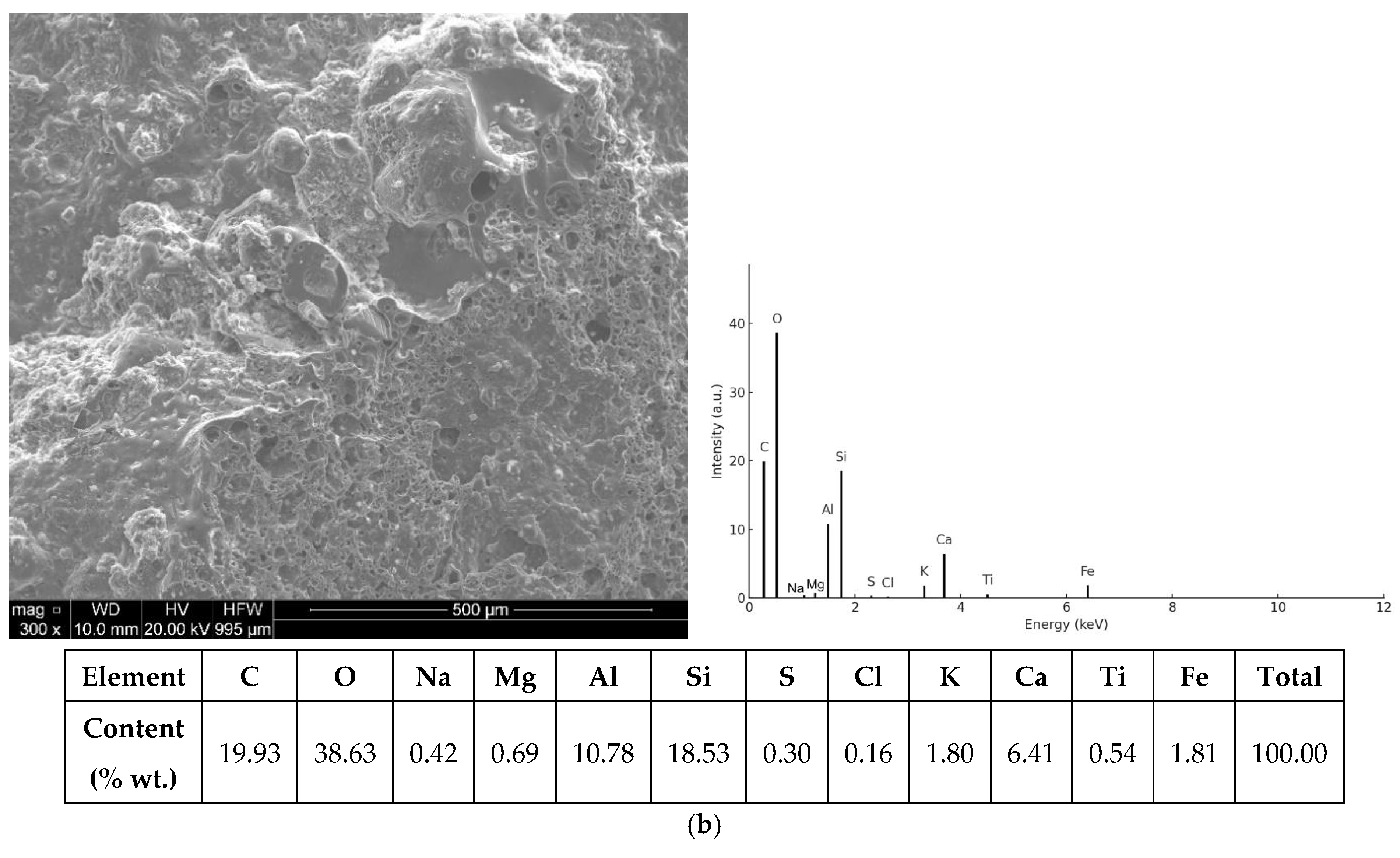
3.2. SEM/EDS Analysis
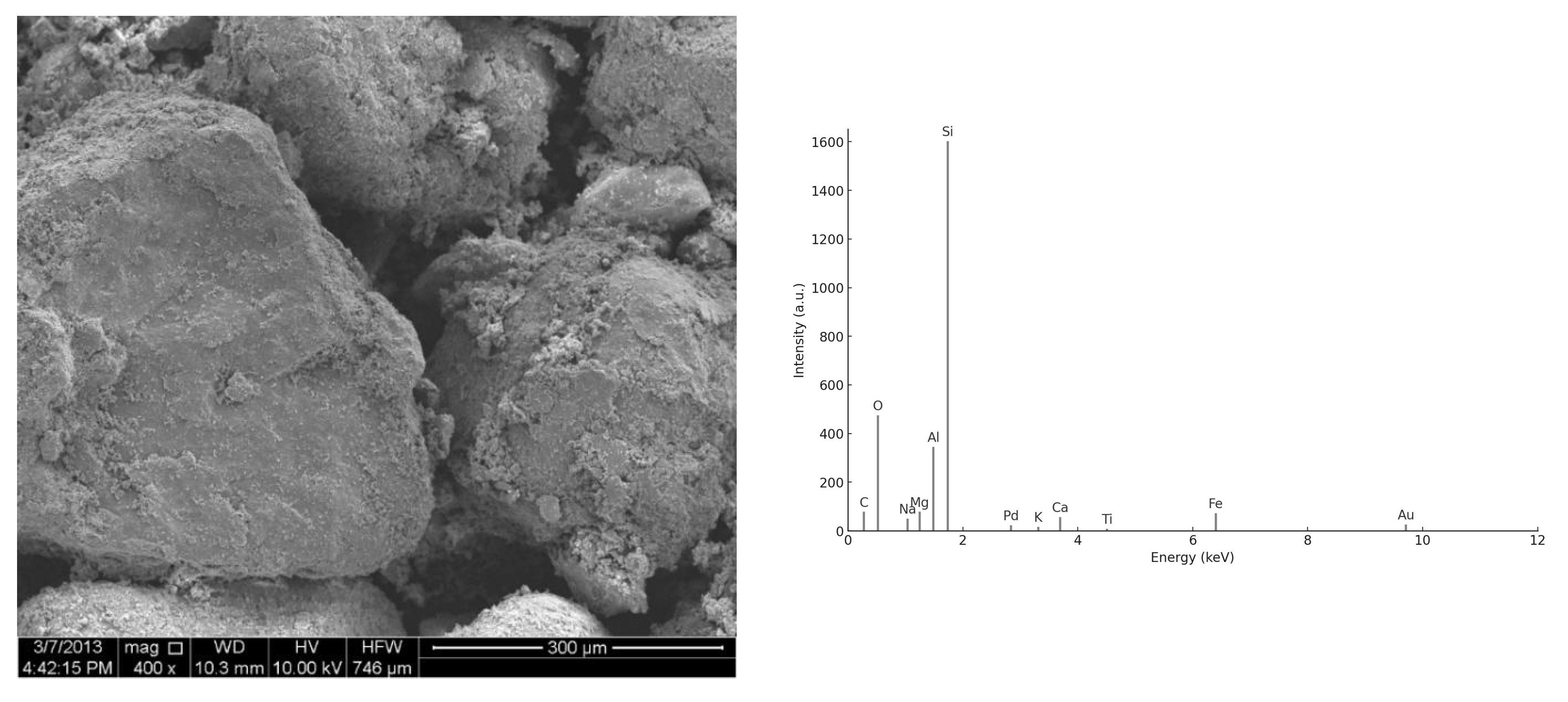
3.2.1. Morphology of UFS and CBA Particles
3.2.2. ITZ and Hydration Products
3.2.3. EDS Spectra
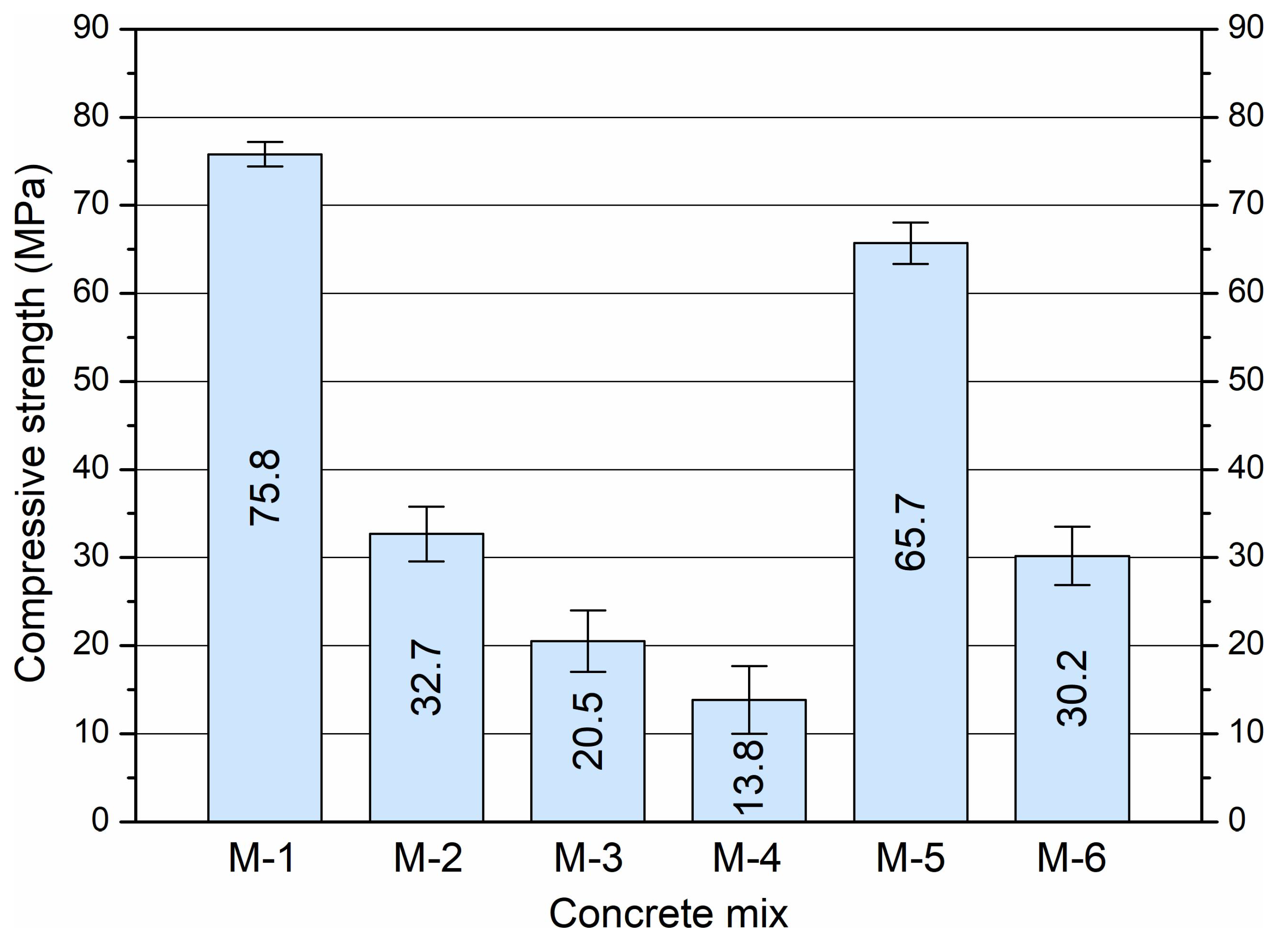
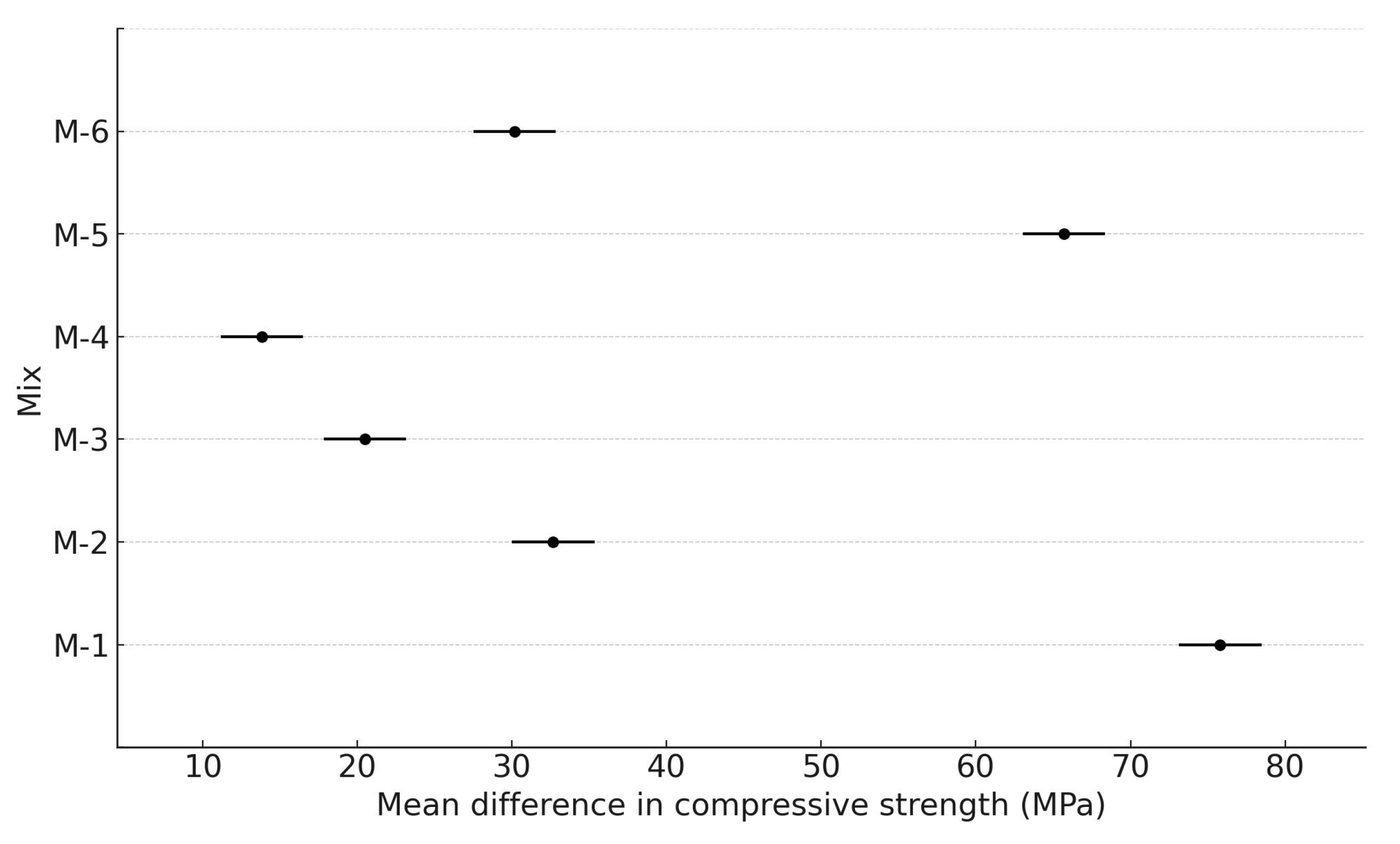
3.3. Compressive Strength
4. Conclusions
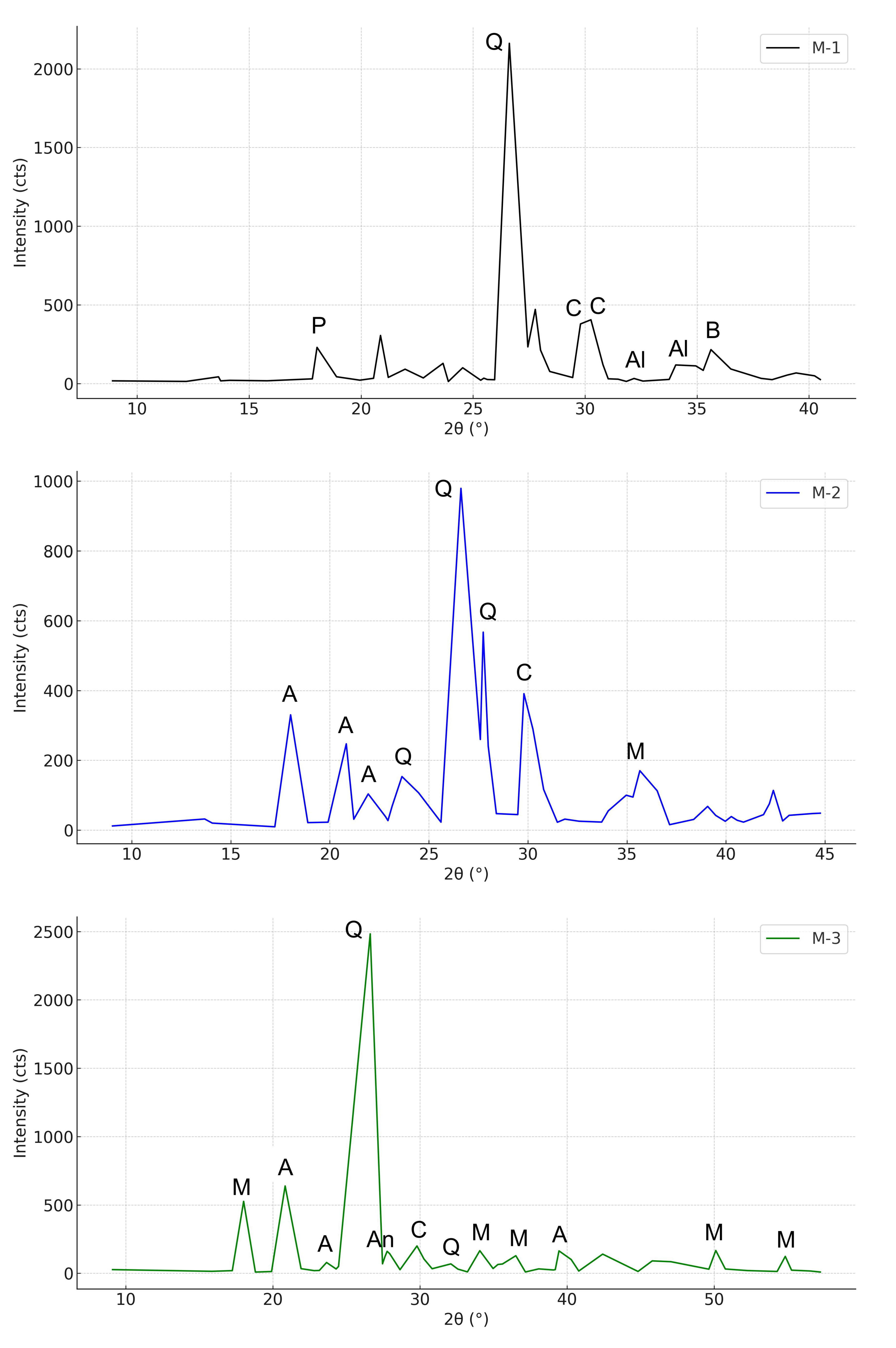
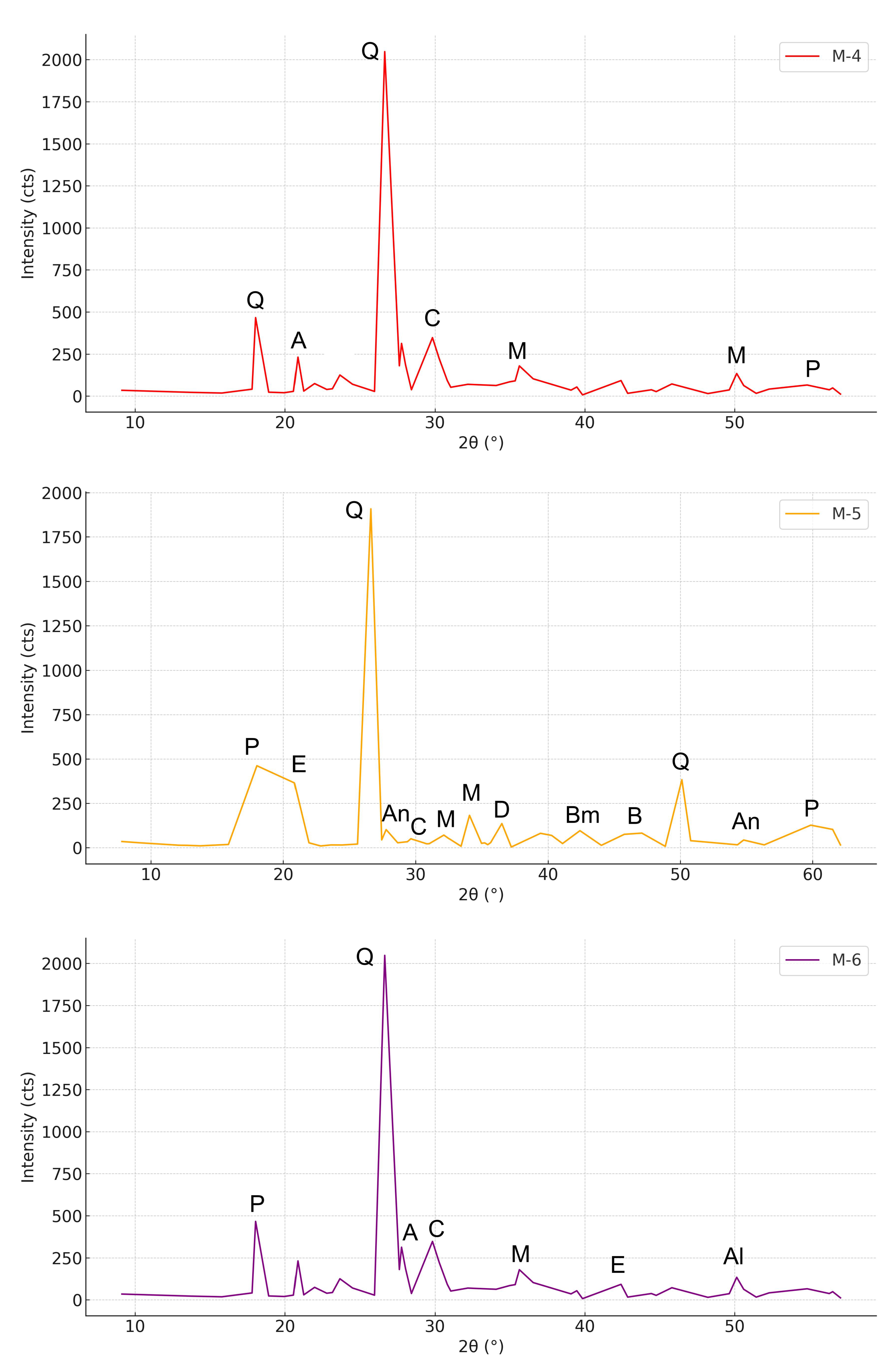
- XRD confirmed that UFS is predominantly composed of quartz, while CBA exhibits a largely amorphous matrix with crystalline inclusions of quartz, mullite, and aluminosilicates. Both materials act mainly as inert fillers without significant pozzolanic reactivity.
- SEM/EDS revealed that the UFS grains are coated with residual clay and carbonaceous binder films, which weaken the ITZ between sand and cement paste. In contrast, CBA particles are highly porous and mechanically fragile, often fracturing under loads and thus becoming the weak phase in the composite.
- Compressive strength tests demonstrated that high replacement levels of UFS and CBA substantially reduce the early age strength of concrete. The severity of this reduction depends on both the type and the amount of waste used. UFS primarily affects strength by degrading ITZ quality, while CBA contributes to loss of strength through aggregate fracture and increased porosity.
- Moderate substitutions, particularly 20% replacement of fine aggregate with CBA, were found to be feasible, resulting in only modest strength reduction and maintaining performance within the range suitable for structural applications. On the contrary, high levels of UFS (≥30%) or coarse CBA (≥40%) caused significant strength penalties and are not recommended without prior treatment.
- Practical implications include the potential for sustainable utilization of UFS and CBA in concrete, provided replacement levels are carefully controlled. Based on the experimental results, replacement levels up to 10–15% for UFS and up to 20% for fine CBA are recommended, as these combinations maintained acceptable mechanical properties. These thresholds reflect the performance boundaries observed in mixes M-5 and M-6, while higher dosages (e.g., 30% UFS or 40% coarse CBA) resulted in excessive strength reduction. Processing techniques such as binder removal (for UFS) and sieving or beneficiation (for CBA) are also encouraged to improve material quality and ensure better integration into the cement matrix.
- Future research should focus on long-term performance (≥90 days), durability aspects (e.g., permeability, freeze-thaw resistance, and sulfate attack), and optimized treatment methods for these industrial by-products. Properly engineered mixes could allow the safe and effective use of UFS and CBA in sustainable concrete applications.
Funding
Institutional Review Board Statement
Informed Consent Statement
Data Availability Statement
Acknowledgments
Conflicts of Interest
References
- Siddique, R.; De Schutter, G.; Noumowé, A. Effect of used-foundry sand on the mechanical properties of concrete. Constr. Build. Mater. 2009, 23, 976–980. [Google Scholar] [CrossRef]
- Dungan, R.S.; Dees, N.H. The Characterization of Total and Leachable Metals in Foundry Molding Sands. J. Environ. Manag. 2009, 90, 539–548. [Google Scholar] [CrossRef]
- American Foundry Society (AFS). All You Ever Wanted to Know About Foundry Sand—Foundry Sand Facts for Civil Engineering, (U.S. FHWA Report); American Foundry Society (AFS): Schaumburg, IL, USA, 2004. [Google Scholar]
- American Foundry Society (AFS). Foundry Sand Facts for Civil Engineers; FHWA-IF-04-004. U.S. Federal Highway Administration (FHWA); American Foundry Society (AFS): Schaumburg, IL, USA, 2004. Available online: https://www.fhwa.dot.gov/pavement/pubs/013791.pdf (accessed on 29 May 2025).
- Naik, T.R.; Singh, S.S.; Hossain, M.M. Used foundry sand in concrete. J. Mater. Civ. Eng. 1996, 8, 94–101. [Google Scholar]
- Güney, Y.; Sari, Y.D.; Yalçin, M.; Tuncan, A.; Donmez, S. Re-usage of waste foundry sand in high-strength concrete. Waste Manag. 2010, 30, 1705–1713. [Google Scholar] [CrossRef] [PubMed]
- Son, B.; Kim, J.H.; Yang, H.S. Effect of waste foundry sand on the mechanical properties and durability of concrete. KSCE J. Civ. Eng. 2018, 22, 4177–4185. [Google Scholar] [CrossRef]
- Torres, A.; Aguayo, F.; Allena, S.; Ellis, M. Utilization of Industrial By-Products for Sustainable Concrete Pavements: A Review of the Influence of Foundry Sand and Bottom Ash. J. Civ. Eng. Constr. 2019, 8, 157–167. [Google Scholar] [CrossRef]
- Manoharan, T.; Laksmanan, D.; Mylsamy, K.; Sivakumar, P.; Sircar, A. Engineering Properties of Concrete with Partial Utilization of Used Foundry Sand. Waste Manag. 2019, 85, 125–135. [Google Scholar] [CrossRef]
- Smarzewski, P. Mechanical Properties of Ultra-High Performance Concrete with Partial Utilization of Waste Foundry Sand. Buildings 2020, 10, 11. [Google Scholar] [CrossRef]
- Ma, H.; Zhu, H.; Wu, C.; Chen, H.; Sun, J.; Liu, J. Study on compressive strength and durability of alkali-activated coal gangue-slag concrete and its mechanism. Powder Technol. 2020, 368, 112–124. [Google Scholar] [CrossRef]
- Singh, M.; Siddique, R. Properties of concrete containing high volumes of coal bottom ash as fine aggregate. J. Clean. Prod. 2015, 91, 269–278. [Google Scholar] [CrossRef]
- ASTM C33/C33M-18; Standard Specification for Concrete Aggregates. ASTM International: West Conshohocken, PA, USA, 2018.
- Aggarwal, P.; Aggarwal, Y.; Gupta, S.M. Effect of coal bottom ash as partial replacement of sand on properties of concrete. Waste Manag. Res. 2010, 28, 467–481. [Google Scholar]
- Ghafoori, N.; Cai, Y. Laboratory-made coal bottom ash as a fine aggregate in concrete. ACI Mater. J. 1998, 95, 603–612. [Google Scholar]
- Smarzewski, P.; Barnat-Hunek, D. Mechanical and durability related properties of high performance concrete made with coal cinder and waste foundry sand. Constr. Build. Mater. 2016, 121, 9–17. [Google Scholar] [CrossRef]
- Park, J.-H.; Bui, Q.-T.; Jung, S.-H.; Yang, I.-H. Selected Strength Properties of Coal Bottom Ash (CBA) Concrete Containing Fly Ash under Different Curing and Drying Conditions. Materials 2021, 14, 5381. [Google Scholar] [CrossRef]
- PN-EN 197-1:2012; Cement—Part 1: Composition, Specifications and Conformity Criteria for Common Cements. Polish Committee for Standardization (PKN): Warsaw, Poland, 2012.
- PN-EN 933-1:2012; Tests for Geometrical Properties of Aggregates—Part 1: Determination of Particle Size Distribution—Sieving Method. Polish Committee for Standardization: Warsaw, Poland, 2012.
- Tangadagi, R.B.; Ravichandran, P.T. Potential Use of Recycled Foundry Sand as Fine Aggregate in Self-Compacting Concrete: Sustainable Engineering Research. Buildings 2025, 15, 815. [Google Scholar] [CrossRef]
- Kumar, R.; Kumar, S. Evaluation of strength and durability performance of waste foundry sand concrete with steel fibers. Struct. Concr. 2021, 22, 2775–2790. [Google Scholar] [CrossRef]
- Lewicki, B. (Ed.) Concrete Construction. Vol. 4: Lightweight Concretes; Arkady: Warsaw, Poland, 1967. [Google Scholar]
- Mohammed, B.S.; Abdullahi, M.; Liew, M.S. A Review on the Use of Bottom Ash in Concrete. Materials 2021, 14, 5179. [Google Scholar] [CrossRef]
- Islam, M.M.; Rahman, M.A.; Hossain, M.M. Performance Evaluation of Coal Bottom Ash as Fine Aggregate in Mortar and Concrete: A Review. Sustainability 2022, 14, 1373. [Google Scholar] [CrossRef]
- Pathak, Y.V.; Patel, J.V. Utilization of Coal Bottom Ash as Partial Fine Aggregate Replacement in High-Performance Concrete. Mater. Today Proc. 2023, 80, 232–238. [Google Scholar] [CrossRef]
- Gupta, T.; Siddique, S.; Sharma, R.K.; Chaudhary, S.; Shrivastava, P. Sustainable utilization of discarded foundry sand and recycled concrete aggregates in concrete. J. Clean. Prod. 2017, 141, 1128–1137. [Google Scholar]
- Al-Bared, M.A.; Alani, A.M. Use of waste basalt dust and recycled aggregate in concrete mixes. Constr. Build. Mater. 2022, 316, 125790. [Google Scholar]
- PN-EN 12390-3:2019-07; Concrete Testing—Part 3: Compressive Strength of Test Specimens. Polish Committee for Standardization (PKN): Warsaw, Poland, 2019.
- Kumar, P.; Bhattacharjee, B. Use of used foundry sand in concrete: A state of art review. Resour. Conserv. Recycl. 2015, 101, 112–123. [Google Scholar]
- Tiwari, S.; Saxena, S.K. Waste foundry sand in concrete: A review. Constr. Build. Mater. 2017, 154, 1109–1126. [Google Scholar]
- Taylor, H.F.W. Cement Chemistry, 2nd ed.; Thomas Telford: London, UK, 1997; ISBN 0727725920. [Google Scholar]
- Siddique, R.; Kaur, G. Use of iron slag as partial replacement of sand to concrete. Constr. Build. Mater. 2012, 35, 710–717. [Google Scholar]
- Naik, T.R. Properties of concrete containing waste foundry sand for highway application. J. Mater. Civ. Eng. 2001, 13, 362–370. [Google Scholar]
- Joshi, R.C.; Lohtia, R.P. Fly Ash in Concrete: Production, Properties and Uses; Gordon and Breach: New York, NY, USA, 1997. [Google Scholar]
- Naik, T.R.; Kraus, R.N.; Siddique, R. Use of Foundry Sand in Concrete and Masonry Products; Report No. CBU-2001-02; UWM Center for By-Products Utilization, University of Wisconsin–Milwaukee: Milwaukee, WI, USA, 2001. [Google Scholar]
- Thomas, C.; Setién, J.; Polanco, J.A.; Alaejos, P.; Sánchez de Juan, M. Durability of recycled aggregate concrete. Constr. Build. Mater. 2013, 40, 1054–1065. [Google Scholar] [CrossRef]


| Compound | Used Foundry Sand | Cement |
|---|---|---|
| SiO2 | 95.3 | 20.92 |
| Al2O3 | 1.9 | 3.50 |
| Fe2O3 | 0.7 | 4.38 |
| CaO | 0.35 | 64.69 |
| MgO | — | 1.20 |
| SO3 | — | 3.07 |
| K2O | — | 0.38 |
| Na2O | — | 0.22 |
| Cl | — | 0.08 |
| Loss on ignition | — | 1.27 |
| Insoluble matter | — | 0.20 |
| Components | Content [% by Weight] | ||
|---|---|---|---|
| CBA Aggregate (Coal Combustion), CHP Lublin [This Study] | EPO Aggregate, Opole Power Plant [Unavailable Web Source] | CBA Aggregate (Polish Coals) [22] | |
| SiO2 | 51.1 | 50 ± 5 | 30–55 |
| Al2O3 | 26.7 | 22.5 ± 4.5 | 12–32 |
| Fe2O3 | 5.44 | 10.7 ± 1.9 | 4–14 |
| CaO | 2.13 | 4.2 ± 0.6 | 2–10 |
| MgO | 1.46 | 3.0 ± 0.7 | 1–6 |
| SO3 | 0.85 | ≤1.0 | 0.5–4 |
| Na2O | 0.45 | – | – |
| K2O | 2.27 | – | – |
| TiO2 | 1.22 | – | – |
| P2O5 | 0.64 | – | – |
| MnO | 0.04 | – | – |
| Cl | 0.13 | – | – |
| Loss on ignition (LOI) | 7.19 | ≤5.5 | 1–35 |
| Concrete Mix Component | Unit | M-1 | M-2 | M-3 | M-4 | M-5 | M-6 |
|---|---|---|---|---|---|---|---|
| CEM I 52.5 cement | (kg/m3) | 372 | 372 | 372 | 372 | 372 | 372 |
| Used foundry sand | (kg/m3) | – | 162 | – | 162 | – | 162 |
| (%) | – | 30 | – | 30 | – | 30 | |
| Natural sand | (kg/m3) | 539 | 377 | 539 | 377 | 539 | 377 |
| Basalt aggregate 2–16 mm | (kg/m3) | 1229 | 1229 | 737 | 737 | 983 | 983 |
| Coal bottom ash | (kg/m3) | – | – | 492 | 492 | 246 | 246 |
| (%) | – | – | 40 | 40 | 20 | 20 | |
| Superplasticizer | (L/m3) | 5.9 | 5.9 | 5.9 | 5.9 | 5.9 | 5.9 |
| Water | (L/m3) | 186 | 186 | 186 | 186 | 186 | 186 |
| Water-to-cement ratio (w/c) | – | 0.5 | 0.5 | 0.5 | 0.5 | 0.5 | 0.5 |
| Waste replacement total ratio | (%) | – | 30 | 40 | 70 | 20 | 50 |
| Fresh concrete density [kg/m3] | (kg/m3) | 2332 | 2332 | 2332 | 2332 | 2332 | 2332 |
| Mix ID | Mean (MPa) | Std Dev (MPa) | CV (%) |
|---|---|---|---|
| M-1 | 75.8 | 1.40 | 1.85 |
| M-2 | 32.7 | 3.13 | 9.58 |
| M-3 | 20.5 | 3.50 | 17.09 |
| M-4 | 13.8 | 3.85 | 27.83 |
| M-5 | 65.7 | 2.33 | 3.54 |
| M-6 | 30.2 | 3.31 | 10.97 |
| Source | Sum of Squares | Degrees of Freedom | F | p-Value |
|---|---|---|---|---|
| C(Mix) | 18,943.50 | 5 | 411.76 | 1.10 × 10⁻²⁶ |
| Residual | 276.04 | 30 | — | — |
| Comparison | Mean Difference (MPa) | p-Value | Lower CI | Upper CI | Significant (Yes/No) |
|---|---|---|---|---|---|
| M-1 vs. M-2 | −43.13 | 0 | −48.46 | −37.81 | yes |
| M-1 vs. M-3 | −55.3 | 0 | −60.63 | −49.97 | yes |
| M-1 vs. M-4 | −61.97 | 0 | −67.29 | −56.64 | yes |
| M-1 vs. M-5 | −10.1 | 0 | −15.43 | −4.77 | yes |
| M-1 vs. M-6 | −45.63 | 0 | −50.96 | −40.31 | yes |
| M-2 vs. M-3 | −12.17 | 0 | −17.49 | −6.84 | yes |
| M-2 vs. M-4 | −18.83 | 0 | −24.16 | −13.51 | yes |
| M-2 vs. M-5 | 33.03 | 0 | 27.71 | 38.36 | yes |
| M-2 vs. M-6 | −2.5 | 0.71 | −7.83 | 2.83 | no |
| M-3 vs. M-4 | −6.67 | 0.01 | −11.99 | −1.34 | yes |
| M-3 vs. M-5 | 45.2 | 0 | 39.87 | 50.53 | yes |
| M-3 vs. M-6 | 9.67 | 0 | 4.34 | 14.99 | yes |
| M-4 vs. M-5 | 51.87 | 0 | 46.54 | 57.19 | yes |
| M-4 vs. M-6 | 16.33 | 0 | 11.01 | 21.66 | yes |
| M-5 vs. M-6 | −35.53 | 0 | −40.86 | −30.21 | yes |
Disclaimer/Publisher’s Note: The statements, opinions and data contained in all publications are solely those of the individual author(s) and contributor(s) and not of MDPI and/or the editor(s). MDPI and/or the editor(s) disclaim responsibility for any injury to people or property resulting from any ideas, methods, instructions or products referred to in the content. |
© 2025 by the author. Licensee MDPI, Basel, Switzerland. This article is an open access article distributed under the terms and conditions of the Creative Commons Attribution (CC BY) license (https://creativecommons.org/licenses/by/4.0/).
Share and Cite
Smarzewski, P. Microstructure and Mechanical Properties of Sustainable Concrete Incorporating Used Foundry Sand and Coal Bottom Ash. Sustainability 2025, 17, 5983. https://doi.org/10.3390/su17135983
Smarzewski P. Microstructure and Mechanical Properties of Sustainable Concrete Incorporating Used Foundry Sand and Coal Bottom Ash. Sustainability. 2025; 17(13):5983. https://doi.org/10.3390/su17135983
Chicago/Turabian StyleSmarzewski, Piotr. 2025. "Microstructure and Mechanical Properties of Sustainable Concrete Incorporating Used Foundry Sand and Coal Bottom Ash" Sustainability 17, no. 13: 5983. https://doi.org/10.3390/su17135983
APA StyleSmarzewski, P. (2025). Microstructure and Mechanical Properties of Sustainable Concrete Incorporating Used Foundry Sand and Coal Bottom Ash. Sustainability, 17(13), 5983. https://doi.org/10.3390/su17135983